EP2369911B1 - Manipulation de gobelets trayeurs - Google Patents
Manipulation de gobelets trayeurs Download PDFInfo
- Publication number
- EP2369911B1 EP2369911B1 EP09744657.9A EP09744657A EP2369911B1 EP 2369911 B1 EP2369911 B1 EP 2369911B1 EP 09744657 A EP09744657 A EP 09744657A EP 2369911 B1 EP2369911 B1 EP 2369911B1
- Authority
- EP
- European Patent Office
- Prior art keywords
- teat
- teats
- horizontal level
- teat cup
- gripper means
- Prior art date
- Legal status (The legal status is an assumption and is not a legal conclusion. Google has not performed a legal analysis and makes no representation as to the accuracy of the status listed.)
- Active
Links
- 210000002445 nipple Anatomy 0.000 claims description 349
- 210000000481 breast Anatomy 0.000 claims description 68
- 238000000034 method Methods 0.000 claims description 36
- 241001465754 Metazoa Species 0.000 claims description 32
- 238000009434 installation Methods 0.000 claims description 12
- 230000004044 response Effects 0.000 claims description 8
- 239000008267 milk Substances 0.000 claims description 7
- 210000004080 milk Anatomy 0.000 claims description 7
- 235000013336 milk Nutrition 0.000 claims description 7
- 238000004590 computer program Methods 0.000 claims description 5
- 238000013459 approach Methods 0.000 description 4
- 230000000295 complement effect Effects 0.000 description 2
- 230000001276 controlling effect Effects 0.000 description 2
- 238000010586 diagram Methods 0.000 description 2
- 238000000605 extraction Methods 0.000 description 2
- 238000007429 general method Methods 0.000 description 2
- 238000003384 imaging method Methods 0.000 description 2
- 230000003287 optical effect Effects 0.000 description 2
- 241000283707 Capra Species 0.000 description 1
- 208000035126 Facies Diseases 0.000 description 1
- 241000124008 Mammalia Species 0.000 description 1
- 241001494479 Pecora Species 0.000 description 1
- 210000000078 claw Anatomy 0.000 description 1
- 238000004140 cleaning Methods 0.000 description 1
- 230000002596 correlated effect Effects 0.000 description 1
- 230000007423 decrease Effects 0.000 description 1
- 230000001419 dependent effect Effects 0.000 description 1
- 230000002452 interceptive effect Effects 0.000 description 1
- 239000000696 magnetic material Substances 0.000 description 1
- 239000004065 semiconductor Substances 0.000 description 1
- 238000012360 testing method Methods 0.000 description 1
- 210000001364 upper extremity Anatomy 0.000 description 1
Images


Classifications
-
- A—HUMAN NECESSITIES
- A01—AGRICULTURE; FORESTRY; ANIMAL HUSBANDRY; HUNTING; TRAPPING; FISHING
- A01J—MANUFACTURE OF DAIRY PRODUCTS
- A01J5/00—Milking machines or devices
- A01J5/017—Automatic attaching or detaching of clusters
- A01J5/0175—Attaching of clusters
Definitions
- the present invention relates generally to automatic milking of animals. More particularly the invention relates to an arrangement for attaching teat cups to the teats of an animal according to the preamble of claim 1 and a milking installation according to claim 8. Moreover, the invention relates to a method according to the preamble of claim 9, a computer program according to claim 16 and a computer readable medium according to claim 17.
- EP 1 211 928 discloses a solution wherein the teat tip positions are estimated by means of light sources and image capturing means. The teat cups are then attached in response to the position estimates.
- US-2007/0215052 discloses a teat location system for automatic milking installations.
- the system includes a light projection source and a camera capable of returning time-of-flight (TOF) information along with intensity information in two dimensions.
- TOF time-of-flight
- three-dimensional data can be generated which represents imaged teats.
- the teat cups can be attached in a relatively straightforward manner.
- WO 2005/122753 reveals a gripper device capable of gripping and simultaneously holding two or more teat cups. By employing such a gripper device the average number of movements between the teat cup magazine and the animal's udder can be reduced, and thus the total attachment time can be shortened.
- EP 1 100 314 shows a milking apparatus having a movable arm for moving teat cups towards the animal to be milked.
- the teat entrance end of at least one teat cup is located at a different level than the teat entrance end of a further one of the teat cups.
- the teat cups can be attached in a simple and reliable manner. Reattachment of any inadvertently detached teat cups is also facilitated thereby.
- the anatomic characteristics of the udder and/or the teats may be such that if two or more teat cups are moved towards the udder in a multi-teat cup gripper, subsequent individual attachment of the teat cups is problematic because in this process the positioning means' view of the teats becomes obstructed and/or the udder and/or at least one teat interferes with the movement of the robotic arm carrying the gripper, the gripper and/or any other object mounted on the arm (e.g. an imaging means). Therefore, multi-grippers may be difficult/inefficient to employ, and sometimes even be excluded. It is also desirable to avoid the complex structure of a multi-teat cup carrier wherein the level of each teat cup is individually controllable. Moreover, the manner in which single-teat cup grippers are employed for teat cup attachment is sometimes sub-optimal from an efficiency point-of-view.
- the object of the present invention is to alleviate the above problems and thus offer a more efficient, reliable and flexible solution for automatically attaching teat cups to milking animals irrespective of their udder and/or teat anatomy.
- the object is achieved by the arrangement defined in appended claim 1, wherein the control means is configured to receive the position estimates.
- the control means is configured to control the robotic arm and the gripper means to remove teat cups from the teat cup magazine in such a manner that the teat-receiving end of each of the at least one teat cup attains a horizontal level in the gripper means, which horizontal level is adapted to the at least one spatial characteristic of the udder.
- the spatial characteristics of the udder registered by the positioning means include one or more of: a respective position estimate for a tip, a center point, and/or a root of each of the teats; a respective estimate of a three-dimensional angle to the horizontal plane for each of the teats, a respective length estimate for each of the teats and a respective thickness estimate for each of the teats. Consequently, the teat cups can be arranged in the gripper means in a manner that is highly adapted to the animal's udder characteristics.
- the gripper means is configured to simultaneously hold at least two teat cups during transport thereof towards the udder.
- the control means is further configured to control the gripper means to grip the at least two teat cups in such a manner that the teat-receiving ends thereof attain a first horizontal level relationship in the gripper means.
- the first horizontal level relationship is adapted to a second horizontal level relationship between the position estimates for the tips of the teats to which the at least two teat cups are to be attached.
- the first horizontal level relationship is further adapted to select an order in which the at least two teat cups are to be attached to the teats based on the second horizontal level relationship.
- the control means is here configured to select the first horizontal level relationship, such that a transit time between removing the at least two teat cups from the teat cup magazine to attaching a last teat cup of the at least two teat cups to its intended teat is expected to become minimal.
- the teat-cup-attachment process can be made highly efficient.
- the positioning means is configured to generate position data representing a respective length estimate of the teats.
- the control means is configured to receive the position data and select the first horizontal level relationship based on a relative length of the teats, such that the teat-receiving end of a teat cup which is to be attached to a comparatively short teat attains a relatively high horizontal level in the gripper means and the teat-receiving end of a teat cup which is to be attached to a comparatively long teat attains a relatively low horizontal level in the gripper means. Consequently, the attachment procedure is further improved.
- control means is configured to select the first horizontal level relationship based on the position estimates, such that an estimated risk is minimized that a movement of the robotic arm becomes restricted by the at least one spatial characteristic of the udder when moving the gripper means to attach the at least two teat cups to the teats.
- the arrangement includes a database, and wherein the control means is configured to store the position estimates in the database.
- the control means is configured to store the position estimates in the database.
- the object is achieved by a milking installation configured to automatically extract milk from at least one animal, wherein the installation includes the above-described arrangement.
- the object is achieved by the method defined in appended claim 8, wherein the method comprises receiving the position estimates, and in response thereto, controlling the robotic arm and the gripper means to remove teat cups from the teat cup magazine in such a manner that the teat- receiving end of each of the at least one teat cup attains a horizontal level in the gripper means which horizontal level is adapted to the at least one spatial characteristic of the udder.
- the object is achieved by a computer program, which is loadable into the internal memory of a computer, and includes software for controlling the above proposed method when the program is run on a computer.
- the object is achieved by a computer readable medium, having a program recorded thereon, where the program is to control a computer to perform the above-proposed method.
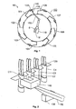
- FIG 1 schematically shows a milking installation 10 configured to automatically extract milk from at least one milking animal, for instance a cow.
- the installation 10 includes at least one milking machine (not shown).
- a teat cup magazine 120 is represented, which holds a number of teat cups, say four.
- the teat cups are connected to the milking machine via one or more milk hoses (not shown).
- the teat cups are also connected to the teats of the animal being milked.
- Figure 1 exemplifies a rotary-parlor type of milking installation 10. Nevertheless, the invention is of course applicable to all kinds of installations where teat cups are to be fetched from a teat cup magazine 120.
- a robotic arm 150 carries a gripper means 140 configured to grip and remove teat cups from the teat cup magazine 120.
- the gripper means 140 is configured to hold at least one teat cup during transport thereof towards an udder of the animal to be milked. According to preferred embodiments of the invention, however, the gripper means 140 is configured to simultaneously hold two or more teat cups.
- the robotic arm 150 is preferably further configured to attach the teat cups to the animal to be milked and release the teat cups from the gripper means 140.
- the gripper means 140 may be configured to return the teat cups to the teat cup magazine 120.
- other means may be used for this task (e.g. pneumatic or vacuum cylinders).
- a control means 110 is configured to control the robotic arm 150 and the gripper means 140.
- the control means 110 includes, or is associated with, a computer readable medium M, e.g. in the form of a memory module, such that the control means 110 has access to the contents of this medium M.
- a program is recorded in the computer readable medium M, and the program is adapted to make the data processor 110 control the process to be described below when the program is run on the processor 110.
- each teat cup has a teat-receiving end.
- the teat cup magazine 120 is configured to store the set of teat cups C1, C2, C3 and C4 during a non-milking state.
- the teat cups C1, C2, C3 and C4 are stored hanging in the teat cup magazine 120 with the teat-receiving ends pointing downwards.
- any other orientation of the teat cups C1, C2, C3 and C4 in the teat cup magazine 120 is equally well conceivable according to the invention.
- the teat cup positioning shown in Figure 2 is advantageous, since it facilitates cleaning of the teat cups C1, C2, C3 and C4, and reduces the risk that dirt and other unwanted objects enter into the teat cups C1, C2, C3 and C4.
- the gripper means 140 is configured to grip and remove teat cups from the teat cup magazine 120.
- the gripper means 140 is also configured to simultaneously hold two teat cups, e.g. C1 and C2, during transport thereof towards the animal to be milked.
- the gripper means 140 may employ different techniques to grip and hold the teat cups.
- the teat cups C1, C2, C3 and C4 may contain a magnetic material, and the gripper means 140 may include an electromagnetic means configured to attract and seize the teat cups under the influence of a magnetic field.
- the gripper means 140 may include suction means and/or friction based claws.
- the gripper means 140 is normally also associated with a switch and/or sensor circuitry adapted to determine when the gripper means 140 has attained an adequate grip of a given teat cup. If the gripper means 140 includes an electromagnetic gripper means, an electric and/or magnetic parameter correlated with the properties of a magnetic field can be used to determine whether or not the gripper means 140 has gripped the teat cup properly.
- the gripper means 140 may be configured to simultaneously hold two or more teat cups (such as C1 and C2 in Figure 2 ), the gripper means 140 is adapted to grip and remove each teat cup separately from the teat cup magazine 120. Preferably, the gripper means 140 is likewise adapted to release the teat cups separately after having been attached to the intended teats.
- the robotic arm 150 carries the gripper means 140, and is configured to transport the gripper means 140 between the teat cup magazine 120 and the teats to which the teat cups C1, C2, C3 and C4 are to be attached.
- the robotic arm 150 must turn each teat cup such that its teat-receiving end points upward before the teat cup reaches the teat to which the teat cup is to be attached. For example, this may be performed by rotating the distal part of the robotic arm 150 around its own axis.
- Figure 2 additionally shows a positioning means 130, which is configured to determine position estimates representing at least one spatial characteristic of an udder where the teats are located to which the teat cups are to be attached.
- the spatial characteristics of the udder may include a respective position estimate for a tip, a center point, and/or a root of each teat.
- the spatial characteristics may include a respective estimate of a three-dimensional angle to the horizontal plane for each of the teats.
- the spatial characteristics may include a respective length estimate for the teats and/or a respective thickness estimate for each of the teats. Further details concerning the spatial characteristics of the udder will be discussed below with reference to Figures 3 , 5, 6 and 7 .
- the positioning means 130 registers reflected wireless energy.
- the positioning means 130 may therefore include one or more of laser source(s) and laser detector(s), imaging device(s) (of conventional and/or of the above-mentioned TOF type), radar(s) and sonar(s).
- the positioning means 130 is preferably arranged on the robotic arm 150.
- the positioning means 130 may be separated from the robotic arm 150, and for example be Iocated on stand in proximity to the expected udder position.
- a stationary positioning means 130 is advantageous because it allows position estimates to be registered already when the animal enters the milking box.
- positioning means 130 may be used in a straightforward manner also to control the robotic arm 150 and its gripper means 140 towards the relevant teat cups in the teat cup magazine 120. Moreover, it is possible to avoid occlusion by moving the positioning means 130 to different viewpoints.
- FIG. 3 shows an exemplifying udder U to whose teats T1, T2, T3 and T4 respectively the teat cups C1, C2, C3 and C4 are to be attached.
- the tip of each teat T1, T2, T3 and T4 has a particular spatial coordinate (x 1 , y 1 , z 1 ), (x 2 , y 2 , z 2 ), (x 3 , y 3 , z 3 ) and (x 4 , y 4 , z 4 ) respectively in a coordinate system X, Y, Z.
- the positioning means 130 is configured to determine a respective estimate of the teat tip positions (x 1 , y 1 , z 1 ), (x 2 , y 2 , z 2 ), (x 3 , y 3 , z 3 ) and (x 4 , y 4 , z 4 ).
- these position estimates may be included in the representation of the spatial characteristics of the udder U.
- the positioning means 130 is configured to determine position estimates of various other spatial characteristics of the udder U. Irrespective of which specific parameters are included in the spatial characteristics of the udder U, it is preferable to update the position estimates repeatedly in order to improve the data quality and to enable adaption to any changes in the spatial characteristics of the udder U.
- control means 110 is configured to store the respective udder characteristics of each animal in a database S, such that the data can be retrieved in connection with subsequent milking of the same animal. As a result, the efficiency of the teat-cup attachment can be further improved.
- the control means 110 is configured to control the robotic arm 150 and the gripper means 140 to remove a number of the teat cups C1, C2, C3 and C4 from the teat cup magazine 120, receive the position estimates (x 1 , y 1 , z 1 ), (x 2 , y 2 , z 2 ), (x 3 , y 3 , z 3 ) and (x 4 , y 4 , z 4 ), and in response thereto control the robotic arm 150 and the gripper means 140 to attach the teat cups to each teat in a given set of the udder's U teats, say T1 and T3.
- the control means 110 controls the gripper means 140 to grip at least one teat cup.
- the gripper means 140 may either transport a single teat cup, or simultaneously carry multiple teat cups between the teat cup magazine 120 and the udder U.
- the gripper means 140 may carry a single teat cup to the udder U for attachment, the udder morphology may determine what constitutes an appropriate level to grip the teat cup relative to its teat-receiving end.
- a spatial relationship between the first teat and at least one second teat may influence the horizontal level at which the first teat cup shall be gripped relative to its teat-receiving end, even if the teat cup(s) to be attached to the at least one second teat will be fetched from the teat cup magazine 120 at a later stage.
- the control means 110 is specifically configured to control the gripper means 140 to grip two teat cups, say C1 and C2, in such a manner that the teat-receiving ends thereof attain a first horizontal level relationship in the gripper means 140.
- Figure 4a shows that the teat-receiving end of a first teat cup C1 has a first horizontal level z C1 and that the teat-receiving end of a second teat cup C2 has a second horizontal level z C2 .
- the first level z C1 is above the second level z C2 , and the teat-receiving ends of the teat cups C1 and C2 point upwards.
- the relationship between z C1 and z C2 is the opposite when gripper means 140 grips the teat cups C1 and C2 and removes them from the teat cup magazine 120.
- the first horizontal level relationship between the first and second levels z C1 and z C2 respectively is adapted to a second horizontal level relationship between the position estimates for the tips of the teats T1 and T3 to which the teat cups C1 and C2 are to be attached.
- the teat T1 is estimated to be positioned at a first horizontal level z 1 and the teat T3 is estimated to be positioned at a second horizontal level z 3 that is somewhat below the first horizontal level z 1 .
- this renders the arrangement of the teat cups C1 and C2 in the gripper means 140 adapted to the teats T1 and T3, if the first teat cup C1 is to be attached to the teat T1, the second teat cup C2 is attached to the teat T3, and the first teat cup C1 is attached before the second teat cup C2.
- the first horizontal level relationship is adapted to the order in which the teat cups C1 and C2 in the gripper means 140 are to be attached to designated teats, i.e. in this example T1 and T3.
- the control means 110 selects the first horizontal level relationship, such that a transit time between removing the teat cups C1 and C2 from the teat cup magazine 120 to attaching a last teat cup, here C2, to its intended teat, here T3, is expected to become minimal.
- FIGs 4b and 4c show gripper means 140 according to embodiments of the invention, which gripper means 140 are configured to simultaneously carry three and four teat cups respectively.
- each gripper means 140 is configured to grip the teat cups in such a manner that the teat-receiving ends thereof attain a first horizontal level relationship in the gripper means 140, which first horizontal level relationship is adapted to a second horizontal level relationship between the position estimates for the tips of the teats to which the teat cups are to be attached.
- each teat cup C 1, C2, C3 or C4 can be positioned in the gripper means 140 at arbitrary horizontal level in a range, which is essentially equal to the extension of the teat cup shell.
- FIG. 5 shows an example of an udder U having teats T1, T2, T3 and T4.
- a first teat T1 has a first length L1 and a first three-dimensional angle ⁇ 1 to the horizontal plane;
- a second teat T2 has a second length L2 and a second three-dimensional angle ⁇ 2 to the horizontal plane;
- a third teat T3 has a third length L3 and a third three-dimensional angle ⁇ 3 to the horizontal plane;
- a fourth teat T4 has a fourth length L4 and a fourth three-dimensional angle ⁇ 4 to the horizontal plane.
- each teat T1, T2, T3 and T4 also has a respective thickness (or average diameter), which may influence the teat cup attachment.
- the thicknesses, the lengths L1, L2, L3, L4, the angles ⁇ 1 , ⁇ 2 , ⁇ 3 and ⁇ 4 are parameters that designate spatial characteristics of the udder U, and these parameters in turn, determine how a set of teat cups should be attached to the teats T1, T2, T3 and T4 respectively via a gripper means 140.
- the positioning means 130 is configured to generate position data representing the respective lengths L1, L2, L3 and L4 of the teats T1, T2, T3 and T4.
- the control means 110 is configured to receive this position data, and based thereon select the first horizontal level relationship, such that the teat-receiving end of a teat cup which is to be attached to a comparatively short teat attains a relatively high horizontal level in the gripper means 140 and the teat-receiving end of a teat cup which is to be attached to a comparatively long teat attains a relatively low horizontal level in the gripper means 140.
- the difference between the levels z C1 and z C2 is comparatively small, and the udder anatomy is such that the positioning means 130 risks interfering with the udder U, it may instead be preferable to attach the teat cups C1 and C2 in a different order.
- the positioning means 130 is configured to register data representing at least one spatial characteristic of the udder U in addition to the above-mentioned data, e.g. the udder's U extension at various levels in front of, behind, on the sides of and/or between the teats T1, T2, T3 and T4.
- the control means 110 is configured to receive the spatial data and based thereon select the first horizontal level relationship, such that an estimated risk is mini mized that a movement of the robotic arm 150 becomes restricted by the at least one spatial characteristic of the udder U when moving the gripper means 140 to attach the teat cups to teats thereof.
- the movement of the robotic arm 150 may be restricted due to various reasons, for example because of the geometric properties of the arm itself, or any device attached thereto (or even the teat cups) are such that these structures interfere with the udder U and/or with at least one of the teats T1, T2, T3 or T4.
- the three-dimensional angles ⁇ 1 , ⁇ 2 , ⁇ 3 and ⁇ 4 for the teats T1, T2, T3 and T4 respectively may also influence the first horizontal level relationship and the most suitable attachment order. For example, if the tips of two or more teats are located at essentially the same horizontal level, it is normally advantageous to attach a teat cup to the most inclined teat first. Namely, if this teat becomes further tilted when attaching teat cups to the other teats, there is an increased risk for attachment failure (e.g. involving folding the teat inside the teat cup) regarding the teat.
- attachment failure e.g. involving folding the teat inside the teat cup
- Figure 6 shows how the robotic arm 150 and the gripper means 140 may be used to attach a pair of teat cups C1 and C2 to designated teats of a milking animal A according to one embodiment of the invention.
- the robotic arm 150 approaches the animal A from the side in front of the hind legs HL and HR and behind the front legs FL and FR, i.e. as is the case for the milking installation shown in Figure 1 .
- a first teat cup C1 may be attached to a first teat T1 and a second teat cup C2 may be attached to a second teat T2.
- a third teat cup may be attached to a third teat T3 and a fourth teat cup may be attached to a fourth teat T4 in a front row of the udder U.
- any other attachment order may prove more efficient depending on the anatomic characteristics of the udder U and its teats T1, T2, T3 and T4.
- Figure 7 shows an embodiment of the invention where the robotic arm 150 instead approaches the animal A from behind, i.e. between the hind legs HL and HR.
- the attachment order for the teat cups C1 and C2 may be determined entirely based on the anatomic characteristics of the udder U and its teats T1, T2, T3 and T4 of the animal A in question as described above.
- a first step 810 checks whether or not the control means has received any position estimates in respect of the udder to whose teats teat cups are to be attached. If no such estimates have been received, the procedure loops back and stays in step 810. If an automatic procedure is available for teaching the system relevant teat positions, such a procedure may be employed to acquire the position estimates in step 810. In any case, when position estimates have been received, the procedure continues to step 820, which determines at least one spatial characteristic of the udder.
- a step 830 controls the gripper means to grip at least one teat cup in such a manner that the teat-receiving end of each teat cup attains a horizontal level in the gripper means, which level is adapted to the at least one spatial characteristic of the udder to whose teats the at least one teat cup is to be attached.
- a step 840 controls the robotic arm to move towards the animal's udder while carrying the at least one teat cup, and controls the gripper means in such a manner that each teat cup in the gripper means is attached to a designated teat of the udder in a given order.
- the positioning means continues to produce updated position estimates for the teat tips, and further preferably also for other relevant anatomic features of the udder.
- a step 850 checks if further teat cups are to be attached. If so, the procedure loops back to step 830 and otherwise the procedure ends. Generally, if attachment and subsequent milking is considered to have been completed successfully, updated position estimates are preferably stored in the database S.
- All of the process steps, as well as any sub-sequence of steps, described with reference to Figure 8 above may be controlled by means of a programmed computer apparatus.
- the embodiments of the invention described above with reference to the drawings comprise computer apparatus and processes performed in computer apparatus, the invention thus also extends to computer programs, particularly computer programs on or in a carrier, adapted for putting the invention into practice.
- the program may be in the form of source code, object code, a code intermediate source and object code such as in partially compiled form, or in any other form suitable for use in the implementation of the process according to the invention.
- the program may either be a part of an operating system, or be a separate application.
- the carrier may be any entity or device capable of carrying the program.
- the carrier may comprise a storage medium, such as a Flash memory, a ROM (Read Only Memory), for example a DVD (Digital VideolVersatile Disk), a CD (Compact Disc) or a semiconductor ROM, an EP-ROM (Erasable Programmable Read-Only Memory), an EEPROM (Electrically Erasable. Programmable Read-Only Memory), or a magnetic recording medium, for example a floppy disc or hard disc.
- the carrier may be a transmissible carrier such as an electrical or optical signal which may be conveyed via electrical or optical cable or by radio or by other means.
- the carrier may be constituted by such cable or device or means.
- the carrier may be an integrated circuit in which the program is embedded, the integrated circuit being adapted for performing, or for use in the performance of, the relevant processes.
- the invention primarily is intended to be utilized in connection with cow milking, the invention is equally well adapted for testing milking machines for any other kind of mammals, such as goats, sheep or buffaloes.
Landscapes
- Life Sciences & Earth Sciences (AREA)
- Animal Husbandry (AREA)
- Environmental Sciences (AREA)
- Manipulator (AREA)
Claims (15)
- Agencement de raccordement de gobelets trayeurs (C1, C2, C3, C4) aux trayons (T1, T2, T3, T4) d'un animal de traite (A), chaque gobelet trayeur comportant une extrémité de réception de trayon configurée pour recevoir un trayon de l'animal (A), l'agencement comprenant :un magasin de gobelets trayeurs (120) configuré pour stocker des gobelets trayeurs (C1, C2, C3, C4),un moyen de préhension (140) configuré pour saisir et retirer des gobelets trayeurs du magasin de gobelets trayeurs (120) et tenir au moins un gobelet trayeur (C1, C2) pendant le transport de celui-ci vers une mamelle (U) sur laquelle les trayons (T1, T2, T3, T4) sont situés,un bras robotisé (150) portant le moyen de préhension (140) et configuré pour transporter le moyen de préhension (140) tenant l'au moins un gobelet trayeur retiré entre le magasin de gobelets trayeurs (120) et les trayons (T1, T2, T3, T4),un moyen de positionnement (130), configuré pour déterminer des estimations de position représentant au moins une caractéristique spatiale de la mamelle (U), etun moyen de commande (110) configuré pour, sur la base des estimations de position, commander le bras robotisé (150) et le moyen de préhension (140) pour qu'ils saisissent et retirent au moins un gobelet trayeur du magasin de gobelets trayeurs (120) et qu'ils raccordent l'au moins un gobelet trayeur (C1, C2, C3, C4) à au moins l'un des trayons (T1, T2, T3, T4), et pour recevoir les estimations de position représentant ladite au moins une caractéristique spatiale de la mamelle (U), caractérisé en ce que le moyen de commande (110) est en outre configuré pour, en réaction à celles-ci, déterminer le niveau horizontal auquel l'au moins un gobelet trayeur doit être saisi par rapport à son extrémité de réception de trayon et pour commander le bras robotisé (150) et le moyen de préhension (140) pour qu'ils retirent l'au moins un gobelet trayeur (C1, C2, C3, C4) du magasin de gobelets trayeurs (120) en saisissant l'au moins un gobelet trayeur au niveau horizontal déterminé par rapport à son extrémité de réception de trayon de telle manière que l'extrémité de réception de trayon de chacun des au moins un gobelets trayeurs (C1, C2) atteint un niveau horizontal (zC1, zC2) dans le moyen de préhension (140), lequel niveau horizontal (zC1, zC2) est adapté à l'au moins une caractéristique spatiale de la mamelle (U).
- Agencement selon la revendication 1, dans lequel l'au moins une caractéristique spatiale de la mamelle (U) comprend au moins un des éléments suivants :une estimation de position (x1, y1, z1; x2, y2, z2; x3, y3, z3; x4, y4, z4) respective pour une pointe, un point central et/ou une racine de chacun des trayons (T1, T2, T3, T4),une estimation respective d'un angle tridimensionnel (α1, α2, α3, α4) par rapport au plan horizontal pour chacun des trayons (T1, T2, T3, T4), une estimation de longueur (L1, L2, L3, L4) respective pour chacun des trayons (T1, T2, T3, T4), etune estimation d'épaisseur respective pour chacun des trayons (T1, T2, T3, T4).
- Agencement selon l'une quelconque des revendications 1 ou 2, dans lequel
le moyen de préhension (140) est configuré pour tenir simultanément au moins deux gobelets trayeurs (C1, C2) pendant le transport de ceux-ci vers la mamelle (U),
le moyen de positionnement (130) est configuré pour déterminer une estimation de position (x1, y1, z1; x2, y2, z2; x3, y3, z3; x4, y4, z4) respective pour une pointe de chacun des trayons (T1, T2, T3, T4), et
le moyen de commande (110) configuré pour recevoir les estimations de position (x1, y1, z1; x2, y2, z2; x3, y3, z3; x4, y4, z4) et en réaction à celles-ci commander le moyen de préhension (140) pour qu'il saisisse les au moins deux gobelets trayeurs (C1, C2) de telle manière que les extrémités de réception de trayon de ceux-ci atteignent un premier rapport de niveau horizontal (zC1, zC2) dans le moyen de préhension (140), lequel premier rapport de niveau horizontal (zC1, zC2) est adapté à un second rapport de niveau horizontal (z1, z3) entre les estimations de position pour les pointes des trayons (T1, T3) auxquels les au moins deux gobelets trayeurs (C1, C2) doivent être raccordés. - Agencement selon la revendication 3, dans lequel le premier rapport de niveau horizontal (zC1, zC2) est en outre adapté pour sélectionner un ordre dans lequel les au moins deux gobelets trayeurs (C1, C2) doivent être raccordés aux trayons (T1, T3), sur la base du second rapport de niveau horizontal (z1, z3), et le moyen de commande (110) est configuré pour sélectionner le premier rapport de niveau horizontal (zC1, zC2) de telle manière qu'un temps de transport entre le retrait des au moins deux gobelets trayeurs (C1, C2) du magasin de gobelets trayeurs (120) et le raccordement d'un dernier gobelet trayeur (C2) des au moins deux gobelets trayeurs (C1, C2) à son trayon (T3) prévu des trayons (T1, T3) est censé devenir minimal.
- Agencement selon l'une quelconque des revendications 3 ou 4, dans lequel :le moyen de positionnement (130) est configuré pour générer des données de position représentant une estimation de longueur (L1, L2, L3, L4) respective des trayons (T1, T2, T3, T4), etle moyen de commande (110) est configuré pour recevoir les données de position et sélectionner le premier rapport de niveau horizontal (zC1, zC2) sur la base d'une longueur relative des trayons de telle manière que l'extrémité de réception de trayon d'un gobelet trayeur (C1) qui doit être raccordée à un trayon (T1) comparativement petit atteint un niveau horizontal (zC1) relativement élevé dans le moyen de préhension (140) et l'extrémité de réception de trayon d'un gobelet trayeur (C2) qui doit être raccordée à un trayon (T3) comparativement long atteint un niveau horizontal (zC2) relativement bas dans le moyen de préhension (140).
- Agencement selon l'une quelconque des revendications 3 à 5, dans lequel le moyen de commande (110) est configuré pour sélectionner le premier rapport de niveau horizontal (zC1, zC2) sur la base des estimations de position de manière à minimiser un risque estimé qu'un mouvement du bras robotisé (150) devienne restreint par l'au moins une caractéristique spatiale de la mamelle (U) lorsque le moyen de préhension (140) est déplacé pour raccorder les au moins deux gobelets trayeurs (C1, C2) aux trayons (T1, T3).
- Installation de traite (10) configurée pour extraire automatiquement du lait d'au moins un animal (A), caractérisée en ce que l'installation (10) comprend au moins un agencement selon l'une quelconque des revendications précédentes.
- Procédé de raccordement de gobelets trayeurs (C1, C2, C3, C4) aux trayons (T1, T2, T3, T4) d'un animal de traite (A), chaque gobelet trayeur comportant une extrémité de réception de trayon configurée pour recevoir un trayon de l'animal (A), le procédé comprenant :la commande d'un moyen de préhension (140) pour qu'il saisisse et retire des gobelets trayeurs d'un magasin de gobelets trayeurs (120) dans lequel les gobelets trayeurs (C1, C2, C3, C4) sont stockés,la commande du moyen de préhension (140) pour qu'il tienne au moins un gobelet trayeur (C1, C2) pendant le transport de celui-ci vers une mamelle (U) sur laquelle les trayons (T1, T2, T3, T4) sont situés,la commande d'un bras robotisé (150) portant le moyen de préhension (140) pour qu'il transporte le moyen de préhension (140) tenant l'au moins un gobelet trayeur retiré entre le magasin de gobelets trayeurs (120) et les trayons (T1, T2, T3, T4),la réception d'estimations de position représentant au moins une caractéristique spatiale de la mamelle (U), etla commande du bras robotisé (150) et du moyen de préhension (140) pour qu'ils saisissent et retirent l'au moins un gobelet trayeur du magasin de gobelets trayeurs et pour qu'ils raccordent l'au moins un gobelet trayeur (C1, C2, C3, C4) à au moins l'un des trayons (T1, T2, T3, T4) sur la base des estimations de position, etla réception des estimations de position représentant ladite au moins une caractéristique spatiale de la mamelle (U), caractérisé en ce qu'il comprend en outre, en réaction à celles-cila détermination du niveau horizontal auquel l'au moins un gobelet trayeur doit être saisi par rapport à son extrémité de réception de trayon et la commande du bras robotisé (150) et du moyen de préhension (140) pour qu'ils retirent l'au moins un gobelet trayeur (C1, C2, C3, C4) du magasin de gobelets trayeurs (120) en saisissant l'au moins un gobelet trayeur au niveau horizontal déterminé par rapport à son extrémité de réception de trayon de telle manière que l'extrémité de réception de trayon de chacun des au moins un gobelets trayeurs (C1, C2) atteint un niveau horizontal (zC1, zC2) dans le moyen de préhension (140), lequel niveau horizontal (zC1, zC2) est adapté à l'au moins une caractéristique spatiale de la mamelle (U).
- Procédé selon la revendication 8, dans lequel l'au moins une caractéristique spatiale de la mamelle (U) comprend au moins un des éléments suivants :une estimation de position (x1, y1, z1; x2, y2, z2; x3, y3, z3; x4, y4, z4) respective pour une pointe, un point central et/ou une racine de chacun des trayons (T1, T2, T3, T4),une estimation respective d'un angle tridimensionnel (α1, α2, α3, α4) par rapport au plan horizontal pour chacun des trayons (T1, T2, T3, T4),une estimation de longueur (L1, L2, L3, L4) respective pour chacun des trayons (T1, T2, T3, T4), etune estimation d'épaisseur respective pour chacun des trayons (T1, T2, T3, T4).
- Procédé selon l'une quelconque des revendications 8 ou 9, dans lequel le moyen de préhension (140) est configuré pour tenir simultanément au moins deux gobelets trayeurs (C1, C2) pendant le transport de ceux-ci vers la mamelle (U), les estimations de positionnement représentent une estimation de position (x1, y1, z1; x2, y2, z2; x3, y3, z3; x4, y4, z4) respective pour une pointe de chacun des trayons (T1, T2, T3, T4), et le procédé comprend :la réception des estimations de position (x1, y1, z1; x2, y2, z2; x3, y3, z3; x4, y4, z4) et en réaction à celles-ci ;la commande du moyen de préhension (140) pour qu'il saisisse les au moins deux gobelets trayeurs (C1, C2) de telle manière que les extrémités de réception de trayon de ceux-ci atteignent un premier rapport de niveau horizontal (zC1, zC2) dans le moyen de préhension (140), lequel premier rapport de niveau horizontal (zC1, zC2) est adapté à un second rapport de niveau horizontal (z1, z3) entre les estimations de position pour les pointes des trayons (T1, T3) auxquels les au moins deux gobelets trayeurs (C1, C2) doivent être raccordés.
- Procédé selon la revendication 10, ledit procédé comprenant :la sélection d'un ordre dans lequel les au moins deux gobelets trayeurs (C1, C2) doivent être raccordés aux trayons (T1, T3) sur la base du second rapport de niveau horizontal, etla sélection du premier rapport de niveau horizontal (zC1, zC2) de telle manière qu'un temps de transport entre le retrait des au moins deux gobelets trayeurs (C1, C2) du magasin de gobelets trayeurs (120) et le raccordement d'un dernier gobelet trayeur (C2) des au moins deux gobelets trayeurs (C1, C2) à son trayon (T3) prévu des trayons (T1, T3) est censé devenir minimal.
- Procédé selon l'une quelconque des revendications 10 ou 11, dans lequel les estimations de position représentent une estimation de longueur (L1, L2, L3, L4) respective des trayons (T1, T2, T3, T4), et le procédé comprend la sélection du premier rapport de niveau horizontal (zC1, zC2) sur la base d'une longueur relative des trayons (T1, T2, T3, T4) de telle manière que l'extrémité de réception de trayon d'un gobelet trayeur (C1) qui doit être raccordée à un trayon (T1) comparativement petit atteint un niveau horizontal (zC1) relativement élevé dans le moyen de préhension (140), et l'extrémité de réception de trayon d'un gobelet trayeur (C2) qui doit être raccordée à un trayon (T3) comparativement long atteint un niveau horizontal (zC2) relativement bas dans le moyen de préhension (140).
- Procédé selon l'une quelconque des revendications 10 à 12, comprenant la sélection du premier rapport de niveau horizontal (zC1, zC2) sur la base des données spatiales de manière à minimiser un risque estimé qu'un mouvement du bras robotisé (150) devienne restreint par l'au moins une caractéristique spatiale de la mamelle (U) lorsque le moyen de préhension (140) est déplacé pour raccorder les au moins deux gobelets trayeurs (C1, C2) aux trayons (T1, T3).
- Programme informatique pouvant être chargé dans la mémoire (M) d'un ordinateur, comprenant un logiciel pour commander les étapes selon l'une quelconque des revendications 8 à 13 quand le programme est exécuté sur l'ordinateur.
- Support lisible par ordinateur (M), présentant un programme enregistré sur celui-ci, le programme étant destiné à faire commander les étapes selon l'une quelconque des revendications 8 à 13 par un ordinateur quand le programme est chargé dans l'ordinateur.
Applications Claiming Priority (2)
| Application Number | Priority Date | Filing Date | Title |
|---|---|---|---|
| SE0802489 | 2008-11-26 | ||
| PCT/EP2009/063679 WO2010060693A1 (fr) | 2008-11-26 | 2009-10-19 | Manipulation de gobelets trayeurs |
Publications (2)
| Publication Number | Publication Date |
|---|---|
| EP2369911A1 EP2369911A1 (fr) | 2011-10-05 |
| EP2369911B1 true EP2369911B1 (fr) | 2016-01-06 |
Family
ID=41600733
Family Applications (1)
| Application Number | Title | Priority Date | Filing Date |
|---|---|---|---|
| EP09744657.9A Active EP2369911B1 (fr) | 2008-11-26 | 2009-10-19 | Manipulation de gobelets trayeurs |
Country Status (3)
| Country | Link |
|---|---|
| US (1) | US8689735B2 (fr) |
| EP (1) | EP2369911B1 (fr) |
| WO (1) | WO2010060693A1 (fr) |
Families Citing this family (16)
| Publication number | Priority date | Publication date | Assignee | Title |
|---|---|---|---|---|
| NZ566631A (en) * | 2008-03-11 | 2011-04-29 | Scott Milktech Ltd | A robotic milking system and a method of attaching milking cups |
| WO2015122784A2 (fr) * | 2008-03-11 | 2015-08-20 | Scott Milktech Limited | Bras de robot de traite et procédé permettant d'attacher des gobelets trayeurs |
| CA2799479C (fr) | 2010-06-17 | 2018-06-19 | Delaval Holding Ab | Pince, robot de traite et amenagement pour traite |
| US9161511B2 (en) * | 2010-07-06 | 2015-10-20 | Technologies Holdings Corp. | Automated rotary milking system |
| US9258975B2 (en) * | 2011-04-28 | 2016-02-16 | Technologies Holdings Corp. | Milking box with robotic attacher and vision system |
| US9215861B2 (en) * | 2011-04-28 | 2015-12-22 | Technologies Holdings Corp. | Milking box with robotic attacher and backplane for tracking movements of a dairy animal |
| US10357015B2 (en) | 2011-04-28 | 2019-07-23 | Technologies Holdings Corp. | Robotic arm with double grabber and method of operation |
| US9510553B2 (en) | 2012-06-12 | 2016-12-06 | Delaval Holding Ab | Arrangement and method for a milking system |
| NL2010406C2 (nl) * | 2013-03-07 | 2014-09-10 | Rotec Engineering B V | Grijper voor het aanbrengen van melkbekers bij een te melken dier, robotarm en melkmachine voorzien daarvan, en werkwijze daarvoor. |
| WO2015065275A1 (fr) * | 2013-10-29 | 2015-05-07 | Delaval Holding Ab | Étui de gobelet-trayeur, gobelet-trayeur, et agencement pour traire automatiquement des animaux |
| NL2012747B1 (nl) * | 2014-05-02 | 2016-02-23 | Technologies Holdings Corp | Dubbele grijper voor het aanbrengen van melkbekers bij een te melken dier, spoelbeker daarvoor en melkmachine voorzien daarvan, en werkwijze voor het melken. |
| CA2965985C (fr) * | 2014-11-06 | 2019-07-09 | Technologies Holdings Corp. | Bras robotique a double organe de saisie et procede de fonctionnement |
| US10817970B2 (en) * | 2016-08-17 | 2020-10-27 | Technologies Holdings Corp. | Vision system with teat detection |
| NL2020983B1 (nl) | 2018-05-24 | 2019-12-02 | Lely Patent Nv | Systeem en werkwijze voor melken van een melkdier |
| RU2769671C1 (ru) * | 2021-04-22 | 2022-04-04 | Федеральное государственное бюджетное научное учреждение «Федеральный научный агроинженерный центр ВИМ» (ФГБНУ ФНАЦ ВИМ) | Способ и устройство для бесконтактного сканирования биологических объектов |
| EP4466986A1 (fr) * | 2023-05-25 | 2024-11-27 | GEA Farm Technologies GmbH | Robot de traite et procédé d'attachement de gobelets trayeurs à une vache dans un processus de traite automatisé par un robot de traite |
Family Cites Families (13)
| Publication number | Priority date | Publication date | Assignee | Title |
|---|---|---|---|---|
| SU1777728A1 (ru) * | 1990-07-12 | 1992-11-30 | Inst Mash Im A A Blagonravova | Автоматизированная доильная установка |
| DE4113700A1 (de) | 1991-04-26 | 1992-10-29 | Dieter Dipl Ing Schillingmann | Verfahren zum automatischen melken von in melkboxen stehenden milchkuehen, sowie melkbox, roboter und melkmodul zur durchfuehrung dieses verfahrens |
| NL9200639A (nl) | 1992-04-06 | 1993-11-01 | Lely Nv C Van Der | Inrichting voor het automatisch melken van dieren. |
| NL9302047A (nl) | 1993-11-26 | 1995-06-16 | Lely Nv C Van Der | Inrichting voor het automatisch melken van dieren. |
| RU2143800C1 (ru) | 1997-10-15 | 2000-01-10 | Лаборатория биотехнических систем Института прикладной механики Уральского отделения РАН | Устройство для ориентации доильных стаканов |
| SE517285C2 (sv) | 1998-07-24 | 2002-05-21 | Delaval Holding Ab | Anordning för automatisk mjölkning av ett djur |
| SE513949C2 (sv) | 1998-08-14 | 2000-12-04 | Alfa Laval Agri Ab | Mjölkrobot samt metod för reglering av robotarmens förflyttning |
| SE517702C2 (sv) | 1998-09-04 | 2002-07-09 | Delaval Holding Ab | Metod och anordning för att manövrera spenkoppar för mjölkning av mjölkdjur |
| SE517052C2 (sv) | 1999-09-15 | 2002-04-09 | Alfa Laval Agri Ab | Apparat och metod för spenkoppsapplicering med hjälp av två alternerande ljuskällor och en kamera |
| WO2003055297A1 (fr) | 2001-12-28 | 2003-07-10 | Idento Electronics B.V. | Procede et dispositif de detection de trayons |
| SE527496C2 (sv) | 2004-06-22 | 2006-03-21 | Delaval Holding Ab | Gripanordning, robotarm och mjölkningsrobot |
| US7895972B2 (en) * | 2005-10-24 | 2011-03-01 | Delaval Holding Ab | Arrangement and method for visual detection in a milking system |
| CA3034793C (fr) | 2006-03-15 | 2023-01-03 | Gea Farm Technologies Gmbh | Duree de deplacement de systeme de localisation de mamelle |
-
2009
- 2009-10-19 EP EP09744657.9A patent/EP2369911B1/fr active Active
- 2009-10-19 WO PCT/EP2009/063679 patent/WO2010060693A1/fr active Application Filing
- 2009-10-19 US US13/130,769 patent/US8689735B2/en active Active
Also Published As
| Publication number | Publication date |
|---|---|
| US20110226183A1 (en) | 2011-09-22 |
| WO2010060693A1 (fr) | 2010-06-03 |
| EP2369911A1 (fr) | 2011-10-05 |
| US8689735B2 (en) | 2014-04-08 |
Similar Documents
| Publication | Publication Date | Title |
|---|---|---|
| EP2369911B1 (fr) | Manipulation de gobelets trayeurs | |
| US10477826B2 (en) | Milking box with robotic attacher | |
| US8281746B2 (en) | Positioning of teat cups | |
| AU2019271943B2 (en) | Double-gripper for the application of teat cups to an animal to be milked, rinse cup for this and milking machine provided therewith, and a method for milking | |
| US20120143375A1 (en) | Milking robot and method for teat cup attachment | |
| EP3400792B1 (fr) | Agencement de stalles d'enceinte de traite | |
| CA2972543C (fr) | Systeme et methode de preparation d'un accessoire de gobelet | |
| EP3241431A1 (fr) | Méthode pour réaliser une opération sur un trayon, et robot à cet effet | |
| EP4145987B1 (fr) | Système et procédé mis en oeuvre par ordinateur pour déterminer un décalage pour un outil de traite dans une machine à traire automatique | |
| CN116157011A (zh) | 机器人挤奶装置 |
Legal Events
| Date | Code | Title | Description |
|---|---|---|---|
| PUAI | Public reference made under article 153(3) epc to a published international application that has entered the european phase |
Free format text: ORIGINAL CODE: 0009012 |
|
| 17P | Request for examination filed |
Effective date: 20110626 |
|
| AK | Designated contracting states |
Kind code of ref document: A1 Designated state(s): AT BE BG CH CY CZ DE DK EE ES FI FR GB GR HR HU IE IS IT LI LT LU LV MC MK MT NL NO PL PT RO SE SI SK SM TR |
|
| DAX | Request for extension of the european patent (deleted) | ||
| 17Q | First examination report despatched |
Effective date: 20130924 |
|
| GRAP | Despatch of communication of intention to grant a patent |
Free format text: ORIGINAL CODE: EPIDOSNIGR1 |
|
| INTG | Intention to grant announced |
Effective date: 20150708 |
|
| GRAS | Grant fee paid |
Free format text: ORIGINAL CODE: EPIDOSNIGR3 |
|
| GRAA | (expected) grant |
Free format text: ORIGINAL CODE: 0009210 |
|
| AK | Designated contracting states |
Kind code of ref document: B1 Designated state(s): AT BE BG CH CY CZ DE DK EE ES FI FR GB GR HR HU IE IS IT LI LT LU LV MC MK MT NL NO PL PT RO SE SI SK SM TR |
|
| REG | Reference to a national code |
Ref country code: GB Ref legal event code: FG4D |
|
| REG | Reference to a national code |
Ref country code: CH Ref legal event code: EP |
|
| REG | Reference to a national code |
Ref country code: IE Ref legal event code: FG4D |
|
| REG | Reference to a national code |
Ref country code: AT Ref legal event code: REF Ref document number: 768002 Country of ref document: AT Kind code of ref document: T Effective date: 20160215 |
|
| REG | Reference to a national code |
Ref country code: DE Ref legal event code: R096 Ref document number: 602009035600 Country of ref document: DE |
|
| REG | Reference to a national code |
Ref country code: NL Ref legal event code: FP |
|
| REG | Reference to a national code |
Ref country code: LT Ref legal event code: MG4D |
|
| REG | Reference to a national code |
Ref country code: AT Ref legal event code: MK05 Ref document number: 768002 Country of ref document: AT Kind code of ref document: T Effective date: 20160106 |
|
| PG25 | Lapsed in a contracting state [announced via postgrant information from national office to epo] |
Ref country code: NO Free format text: LAPSE BECAUSE OF FAILURE TO SUBMIT A TRANSLATION OF THE DESCRIPTION OR TO PAY THE FEE WITHIN THE PRESCRIBED TIME-LIMIT Effective date: 20160406 Ref country code: IT Free format text: LAPSE BECAUSE OF FAILURE TO SUBMIT A TRANSLATION OF THE DESCRIPTION OR TO PAY THE FEE WITHIN THE PRESCRIBED TIME-LIMIT Effective date: 20160106 Ref country code: HR Free format text: LAPSE BECAUSE OF FAILURE TO SUBMIT A TRANSLATION OF THE DESCRIPTION OR TO PAY THE FEE WITHIN THE PRESCRIBED TIME-LIMIT Effective date: 20160106 Ref country code: FI Free format text: LAPSE BECAUSE OF FAILURE TO SUBMIT A TRANSLATION OF THE DESCRIPTION OR TO PAY THE FEE WITHIN THE PRESCRIBED TIME-LIMIT Effective date: 20160106 Ref country code: ES Free format text: LAPSE BECAUSE OF FAILURE TO SUBMIT A TRANSLATION OF THE DESCRIPTION OR TO PAY THE FEE WITHIN THE PRESCRIBED TIME-LIMIT Effective date: 20160106 Ref country code: GR Free format text: LAPSE BECAUSE OF FAILURE TO SUBMIT A TRANSLATION OF THE DESCRIPTION OR TO PAY THE FEE WITHIN THE PRESCRIBED TIME-LIMIT Effective date: 20160407 |
|
| PG25 | Lapsed in a contracting state [announced via postgrant information from national office to epo] |
Ref country code: LV Free format text: LAPSE BECAUSE OF FAILURE TO SUBMIT A TRANSLATION OF THE DESCRIPTION OR TO PAY THE FEE WITHIN THE PRESCRIBED TIME-LIMIT Effective date: 20160106 Ref country code: PL Free format text: LAPSE BECAUSE OF FAILURE TO SUBMIT A TRANSLATION OF THE DESCRIPTION OR TO PAY THE FEE WITHIN THE PRESCRIBED TIME-LIMIT Effective date: 20160106 Ref country code: IS Free format text: LAPSE BECAUSE OF FAILURE TO SUBMIT A TRANSLATION OF THE DESCRIPTION OR TO PAY THE FEE WITHIN THE PRESCRIBED TIME-LIMIT Effective date: 20160506 Ref country code: PT Free format text: LAPSE BECAUSE OF FAILURE TO SUBMIT A TRANSLATION OF THE DESCRIPTION OR TO PAY THE FEE WITHIN THE PRESCRIBED TIME-LIMIT Effective date: 20160506 Ref country code: AT Free format text: LAPSE BECAUSE OF FAILURE TO SUBMIT A TRANSLATION OF THE DESCRIPTION OR TO PAY THE FEE WITHIN THE PRESCRIBED TIME-LIMIT Effective date: 20160106 Ref country code: LT Free format text: LAPSE BECAUSE OF FAILURE TO SUBMIT A TRANSLATION OF THE DESCRIPTION OR TO PAY THE FEE WITHIN THE PRESCRIBED TIME-LIMIT Effective date: 20160106 Ref country code: SE Free format text: LAPSE BECAUSE OF FAILURE TO SUBMIT A TRANSLATION OF THE DESCRIPTION OR TO PAY THE FEE WITHIN THE PRESCRIBED TIME-LIMIT Effective date: 20160106 |
|
| REG | Reference to a national code |
Ref country code: DE Ref legal event code: R097 Ref document number: 602009035600 Country of ref document: DE |
|
| PG25 | Lapsed in a contracting state [announced via postgrant information from national office to epo] |
Ref country code: DK Free format text: LAPSE BECAUSE OF FAILURE TO SUBMIT A TRANSLATION OF THE DESCRIPTION OR TO PAY THE FEE WITHIN THE PRESCRIBED TIME-LIMIT Effective date: 20160106 Ref country code: EE Free format text: LAPSE BECAUSE OF FAILURE TO SUBMIT A TRANSLATION OF THE DESCRIPTION OR TO PAY THE FEE WITHIN THE PRESCRIBED TIME-LIMIT Effective date: 20160106 |
|
| PLBE | No opposition filed within time limit |
Free format text: ORIGINAL CODE: 0009261 |
|
| STAA | Information on the status of an ep patent application or granted ep patent |
Free format text: STATUS: NO OPPOSITION FILED WITHIN TIME LIMIT |
|
| PG25 | Lapsed in a contracting state [announced via postgrant information from national office to epo] |
Ref country code: SK Free format text: LAPSE BECAUSE OF FAILURE TO SUBMIT A TRANSLATION OF THE DESCRIPTION OR TO PAY THE FEE WITHIN THE PRESCRIBED TIME-LIMIT Effective date: 20160106 Ref country code: SM Free format text: LAPSE BECAUSE OF FAILURE TO SUBMIT A TRANSLATION OF THE DESCRIPTION OR TO PAY THE FEE WITHIN THE PRESCRIBED TIME-LIMIT Effective date: 20160106 Ref country code: CZ Free format text: LAPSE BECAUSE OF FAILURE TO SUBMIT A TRANSLATION OF THE DESCRIPTION OR TO PAY THE FEE WITHIN THE PRESCRIBED TIME-LIMIT Effective date: 20160106 Ref country code: RO Free format text: LAPSE BECAUSE OF FAILURE TO SUBMIT A TRANSLATION OF THE DESCRIPTION OR TO PAY THE FEE WITHIN THE PRESCRIBED TIME-LIMIT Effective date: 20160106 |
|
| 26N | No opposition filed |
Effective date: 20161007 |
|
| PG25 | Lapsed in a contracting state [announced via postgrant information from national office to epo] |
Ref country code: BE Free format text: LAPSE BECAUSE OF FAILURE TO SUBMIT A TRANSLATION OF THE DESCRIPTION OR TO PAY THE FEE WITHIN THE PRESCRIBED TIME-LIMIT Effective date: 20160106 |
|
| PG25 | Lapsed in a contracting state [announced via postgrant information from national office to epo] |
Ref country code: BG Free format text: LAPSE BECAUSE OF FAILURE TO SUBMIT A TRANSLATION OF THE DESCRIPTION OR TO PAY THE FEE WITHIN THE PRESCRIBED TIME-LIMIT Effective date: 20160406 Ref country code: SI Free format text: LAPSE BECAUSE OF FAILURE TO SUBMIT A TRANSLATION OF THE DESCRIPTION OR TO PAY THE FEE WITHIN THE PRESCRIBED TIME-LIMIT Effective date: 20160106 |
|
| REG | Reference to a national code |
Ref country code: CH Ref legal event code: PL |
|
| GBPC | Gb: european patent ceased through non-payment of renewal fee |
Effective date: 20161019 |
|
| REG | Reference to a national code |
Ref country code: IE Ref legal event code: MM4A |
|
| REG | Reference to a national code |
Ref country code: FR Ref legal event code: ST Effective date: 20170630 |
|
| PG25 | Lapsed in a contracting state [announced via postgrant information from national office to epo] |
Ref country code: GB Free format text: LAPSE BECAUSE OF NON-PAYMENT OF DUE FEES Effective date: 20161019 Ref country code: FR Free format text: LAPSE BECAUSE OF NON-PAYMENT OF DUE FEES Effective date: 20161102 Ref country code: CH Free format text: LAPSE BECAUSE OF NON-PAYMENT OF DUE FEES Effective date: 20161031 Ref country code: LI Free format text: LAPSE BECAUSE OF NON-PAYMENT OF DUE FEES Effective date: 20161031 |
|
| PG25 | Lapsed in a contracting state [announced via postgrant information from national office to epo] |
Ref country code: LU Free format text: LAPSE BECAUSE OF NON-PAYMENT OF DUE FEES Effective date: 20161019 |
|
| PG25 | Lapsed in a contracting state [announced via postgrant information from national office to epo] |
Ref country code: IE Free format text: LAPSE BECAUSE OF NON-PAYMENT OF DUE FEES Effective date: 20161019 |
|
| PG25 | Lapsed in a contracting state [announced via postgrant information from national office to epo] |
Ref country code: CY Free format text: LAPSE BECAUSE OF FAILURE TO SUBMIT A TRANSLATION OF THE DESCRIPTION OR TO PAY THE FEE WITHIN THE PRESCRIBED TIME-LIMIT Effective date: 20160106 Ref country code: HU Free format text: LAPSE BECAUSE OF FAILURE TO SUBMIT A TRANSLATION OF THE DESCRIPTION OR TO PAY THE FEE WITHIN THE PRESCRIBED TIME-LIMIT; INVALID AB INITIO Effective date: 20091019 |
|
| PG25 | Lapsed in a contracting state [announced via postgrant information from national office to epo] |
Ref country code: MK Free format text: LAPSE BECAUSE OF FAILURE TO SUBMIT A TRANSLATION OF THE DESCRIPTION OR TO PAY THE FEE WITHIN THE PRESCRIBED TIME-LIMIT Effective date: 20160106 Ref country code: MT Free format text: LAPSE BECAUSE OF NON-PAYMENT OF DUE FEES Effective date: 20161031 Ref country code: TR Free format text: LAPSE BECAUSE OF FAILURE TO SUBMIT A TRANSLATION OF THE DESCRIPTION OR TO PAY THE FEE WITHIN THE PRESCRIBED TIME-LIMIT Effective date: 20160106 Ref country code: MC Free format text: LAPSE BECAUSE OF FAILURE TO SUBMIT A TRANSLATION OF THE DESCRIPTION OR TO PAY THE FEE WITHIN THE PRESCRIBED TIME-LIMIT Effective date: 20160106 |
|
| PGFP | Annual fee paid to national office [announced via postgrant information from national office to epo] |
Ref country code: DE Payment date: 20201006 Year of fee payment: 12 |
|
| REG | Reference to a national code |
Ref country code: DE Ref legal event code: R119 Ref document number: 602009035600 Country of ref document: DE |
|
| PG25 | Lapsed in a contracting state [announced via postgrant information from national office to epo] |
Ref country code: DE Free format text: LAPSE BECAUSE OF NON-PAYMENT OF DUE FEES Effective date: 20220503 |
|
| PGFP | Annual fee paid to national office [announced via postgrant information from national office to epo] |
Ref country code: NL Payment date: 20240917 Year of fee payment: 16 |