EP2369557B1 - Check deposit apparatus - Google Patents
Check deposit apparatus Download PDFInfo
- Publication number
- EP2369557B1 EP2369557B1 EP09835283.4A EP09835283A EP2369557B1 EP 2369557 B1 EP2369557 B1 EP 2369557B1 EP 09835283 A EP09835283 A EP 09835283A EP 2369557 B1 EP2369557 B1 EP 2369557B1
- Authority
- EP
- European Patent Office
- Prior art keywords
- check
- sensor group
- unit
- sensor
- feed
- Prior art date
- Legal status (The legal status is an assumption and is not a legal conclusion. Google has not performed a legal analysis and makes no representation as to the accuracy of the status listed.)
- Active
Links
Images


Classifications
-
- G—PHYSICS
- G07—CHECKING-DEVICES
- G07F—COIN-FREED OR LIKE APPARATUS
- G07F19/00—Complete banking systems; Coded card-freed arrangements adapted for dispensing or receiving monies or the like and posting such transactions to existing accounts, e.g. automatic teller machines
- G07F19/20—Automatic teller machines [ATMs]
- G07F19/202—Depositing operations within ATMs
-
- G—PHYSICS
- G07—CHECKING-DEVICES
- G07D—HANDLING OF COINS OR VALUABLE PAPERS, e.g. TESTING, SORTING BY DENOMINATIONS, COUNTING, DISPENSING, CHANGING OR DEPOSITING
- G07D11/00—Devices accepting coins; Devices accepting, dispensing, sorting or counting valuable papers
- G07D11/009—Depositing devices
-
- G—PHYSICS
- G06—COMPUTING OR CALCULATING; COUNTING
- G06Q—INFORMATION AND COMMUNICATION TECHNOLOGY [ICT] SPECIALLY ADAPTED FOR ADMINISTRATIVE, COMMERCIAL, FINANCIAL, MANAGERIAL OR SUPERVISORY PURPOSES; SYSTEMS OR METHODS SPECIALLY ADAPTED FOR ADMINISTRATIVE, COMMERCIAL, FINANCIAL, MANAGERIAL OR SUPERVISORY PURPOSES, NOT OTHERWISE PROVIDED FOR
- G06Q20/00—Payment architectures, schemes or protocols
- G06Q20/04—Payment circuits
- G06Q20/042—Payment circuits characterized in that the payment protocol involves at least one cheque
-
- G—PHYSICS
- G07—CHECKING-DEVICES
- G07D—HANDLING OF COINS OR VALUABLE PAPERS, e.g. TESTING, SORTING BY DENOMINATIONS, COUNTING, DISPENSING, CHANGING OR DEPOSITING
- G07D11/00—Devices accepting coins; Devices accepting, dispensing, sorting or counting valuable papers
- G07D11/009—Depositing devices
- G07D11/0093—Drop boxes
-
- G—PHYSICS
- G07—CHECKING-DEVICES
- G07D—HANDLING OF COINS OR VALUABLE PAPERS, e.g. TESTING, SORTING BY DENOMINATIONS, COUNTING, DISPENSING, CHANGING OR DEPOSITING
- G07D11/00—Devices accepting coins; Devices accepting, dispensing, sorting or counting valuable papers
- G07D11/10—Mechanical details
- G07D11/16—Handling of valuable papers
-
- G—PHYSICS
- G07—CHECKING-DEVICES
- G07D—HANDLING OF COINS OR VALUABLE PAPERS, e.g. TESTING, SORTING BY DENOMINATIONS, COUNTING, DISPENSING, CHANGING OR DEPOSITING
- G07D7/00—Testing specially adapted to determine the identity or genuineness of valuable papers or for segregating those which are unacceptable, e.g. banknotes that are alien to a currency
- G07D7/16—Testing the dimensions
- G07D7/162—Length or width
-
- G—PHYSICS
- G07—CHECKING-DEVICES
- G07F—COIN-FREED OR LIKE APPARATUS
- G07F19/00—Complete banking systems; Coded card-freed arrangements adapted for dispensing or receiving monies or the like and posting such transactions to existing accounts, e.g. automatic teller machines
- G07F19/20—Automatic teller machines [ATMs]
Definitions
- the present invention relates to a check deposit apparatus, and more particularly, to a check deposit apparatus having an abnormal check sensing function for sensing and returning a check that does not meet a standard size.
- an Automated Teller Machine includes an input unit for inputting information, a screen unit for displaying financial service menu and transaction situation, and a check deposit apparatus through which a customer can insert or receive a check for deposit/withdrawal transaction. The customer deposits and withdraws a check through the check deposit apparatus.
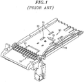
- Fig. 1 is a perspective view illustrating a part of an insertion unit and an alignment unit of a conventional check deposit apparatus.
- the check deposit apparatus includes an insertion unit 10 through which a customer inserts a check from the outside or receives a check returned from the inside, and an alignment unit 30 for pushing and aligning the inserted check to one side of a feed path 20 while feeding the check inwards along the feed path 20.
- the check deposit apparatus may further include a check reading unit (not shown) for checking genuineness and information of the fed check and a multiple sheet sensing unit (not shown) for sensing whether or not the fed check is formed of a single sheet or multiple sheets.
- the position of the alignment unit 30 for aligning a check is slightly biased toward a direction in which a check is pushed, e.g., toward a right side of the feed path 20.
- checks that are inserted at one time by a user are aligned and scanned one by one so that the genuineness and the information thereof can be checked.
- the overlapped checks may be returned to a user so that the user can insert them one by one.
- the checks are returned, they are returned one by one along the feed path 20. For example, even if a user inserts five checks into the insertion unit 10 at one time, the five checks are not returned to the user at one time. Instead, the user receives the five checks consecutively one by one through the insertion unit 10.
- a check may be inserted in a state that does not enable it to be fed by the alignment unit in the check deposit apparatus.
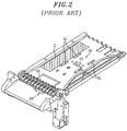
- a check 'c' folded in half along its length may be inserted into the insertion unit 10.
- the inserted check 'c' is fed by a feed roller 12 and then remains in that state without being fed further.
- a damaged check or a medium such as a name card or the like other than a check
- a check 'c' is fed by the feed roller 12 and then is stacked without reaching the alignment roller 31.
- a check having a non-standard size or another medium may be inserted. In that case, it can be fed but cannot be recognized as a check, which causes an error.
- the feed path is designed in accordance with the various standard sizes of the checks.
- a check having a size smaller than the standard sizes is inserted, it is directed to the check reading unit for checking genuineness and information of the check fed along the feed path.
- check or an abnormal medium
- Document US 6 145 737 A on which the preamble of claim 1 is based discloses a check deposit apparatus comprising: an insertion unit for inserting a check from outside to deposit, a feed unit including a feed roller that feeds the inserted check along a feed path, an alignment unit including an alignment roller that feeds the check fed from the feed unit to one side of the feed path and also aligns the check, and a check reading unit for reading information of the check aligned by the alignment unit.
- Document US2008/0149708 A1 discloses a banking machine system including a deposit accepting device which may operate to receive a stack of sheets, wherein sheets being determined not to have a specific property are returned to a user of the machine.
- this document shows alignment sensors, edge sensors and even sensors for determining the width of the sheet.
- document US2007/0114717 A1 discloses a bill handling apparatus, wherein sensors for detecting passage of the bills are arranged on the conveyance path in order to improve inspection or maintenance of the apparatus.
- Fig. 4 is a schematic diagram showing an internal configuration of a check deposit apparatus in accordance with an embodiment of the present invention.
- Fig. 5 is a perspective view illustrating arrangement of sensors in an insertion unit and an alignment unit of the check deposit apparatus shown in Fig. 4 .
- Fig. 6 is a top view illustrating distances between the sensors shown in Fig. 5 .
- Fig. 7 shows a control unit that performs a check return process and a check deposit transaction based on sensed results of the sensors.
- a feed path 20 is formed by a space between an upper member 21 and a lower member 22 which correspond to each other.
- Figs. 5 and 6 illustrate the feed path 20 on the lower member 22.
- the check deposit apparatus for sensing an abnormal check by using sensors includes an insertion unit 10 that is used for a user to insert a check from outside for deposit, a feed unit furnished with the feed path 20 and a feed roller 12 that feed the inserted check, an alignment unit 30 furnished with an alignment roller 31 that aligns the check fed from the feed unit to one side of the feed path 20, a check reading unit 40 for reading information of the check aligned in the alignment unit, a first and a second sensor group 23 and 24 for judging whether or not the check inserted into the insertion unit 10 has a standard size that enables it to be fed normally, third sensor groups 25 and 26 for judging whether the check aligned in the alignment unit 30 has a standard size that enables it to be read normally in the check reading unit 40, and a control unit 70 (see Fig. 7 ) for determining whether to deposit or return the check in question based on the information sensed by the first to the third sensor group.
- the first and the second sensor group 23 and 24 respectively include a plurality of sensors 23a and 23b and 24a to 24c for sensing a length and a width of a check.
- the third sensor groups 25 and 26 include a plurality of sensors 25a to 25c and 26a and 26b for sensing a length and a width of a check.
- the control unit 70 is installed inside the check deposit apparatus. When at least one of the length and the width of the check sensed by the first to the third sensor group 23 to 26 does not meet the standard size, the control unit 70 determines the corresponding check as a check that cannot be fed and returns the corresponding check.
- the second sensor group 24 is provided between the insertion unit 10 and the alignment unit 30 of the check deposit apparatus and senses whether or not an abnormal bill is inserted.
- the abnormal bill indicates a check having an abnormally small length in the horizontal direction (including a medium such as a name card or the like other than a check) and a check having an abnormally small width in the vertical direction (e.g., a check folded in half or a check cut in half). More specifically, the second sensor group 24 senses whether or not the placed check has a width smaller than a distance between the alignment roller 31 and one side of the feed path 20.
- the second sensor group 24 includes three sensors 24a to 24c installed spaced apart from one another by predetermined distances d1 and dl' and arranged side by side in the vertical direction perpendicular to the horizontal direction in which a check is inserted.
- the number of the sensors 24a to 24c may be smaller than or equal to three, or may be greater than or equal to four.
- the first sensor group 23 for sensing whether or not the abnormal bill is inserted is installed at a predetermined distance d2 apart from the second sensor group 24.
- the first sensor group 23 senses whether or not a check that cannot be fed further due to its length smaller than a distance between the feed roller 12 and the alignment roller 31 is inserted.
- the control unit 70 can readily return to a user a check having a length smaller than the distance d2 between the first sensor group 23 and the second sensor group 24 or a check having a width smaller than the distance dl' between the sensors 24a to 24c of the second sensor group and the distance d1 between the sensor 24a of the second sensor group 24 and one side of the feed path based on the sensing results of the sensor groups 23 and 24.
- the control unit 70 can return the check by generating, e.g., a control signal for reversely rotating the feed roller 12 toward the insertion unit 10.
- the control unit 70 can feed the check toward a storing unit 60 for storing a check so that the check can be deposited.
- the third sensor groups 25 and 26 include one or more sensors 25a, 25b and 26b for sensing a length of a check in order to judge whether or not an aligned check meets the standard size that enables it to be read normally by the check reading unit 40 and one or more sensors 25b, 25c and 26a for measuring a width of a check.
- the control unit 70 controls a check having a length or a width that does not meet the standard size to be returned.
- a check having a size smaller than a distance d3 between the sensors 25a and 25b and a distance d4 between the sensors 25a or 25b and 26b or 26a can be determined as a check that does not meet the standard size, according to whether or not both the length and the width of the aligned check are sensed by the third sensor groups 25 and 26.
- the distances d3 and d4 between the sensors can be defined in correspondence to the standard size of the smallest check among the checks that can be read by the check reading unit 40.
- a check that can be sensed by all of three sensors i.e., the sensor 25b, the sensor 26b spaced apart from the sensor 25b by a predetermined distance, and the sensor 26a spaced apart from the sensor 25b by a predetermined distance, can be judged as a check that meets the standard size.
- the control unit 70 can return the check by generating, e.g., a control signal for reversely rotating the alignment roller 31 and the feed roller 12 toward the insertion unit 10, as illustrated in Fig. 7 .
- the control unit 70 can feed the check toward the storing unit 60 so that the check can be deposited.
- Each sensor in the first to the third sensor group 23 to 26 can be configured with an optical sensor including a pair of light emitting unit and light receiving unit.
- the light emitting unit of the optical sensor can be positioned at the lower member 22 forming the feed path 20, and the light receiving unit can be positioned at the upper member 21.
- Each sensor in the first to the third sensor group 23 to 26 may also be configured to sense whether or not the check is formed of a single sheet or multiple sheets.
- whether or not the check is formed of a single sheet or multiple sheets can be sensed by comparing an amount of optical signal received by the light receiving unit with a reference value, the optical signal being generated from the light emitting unit of each sensor in the first to the third sensor group 23 to 26, irradiated to the check and then received by the light receiving unit.
- the check deposit apparatus of the present invention When the check deposit apparatus of the present invention is configured to allow a user to deposit checks one by one, a plurality of checks inserted at one time is controlled to be returned.
- one of the sensor groups 23 to 26 senses whether or not the check is formed of a single sheet or multiple sheets.
- the control unit 70 stops the operation of other units and readily returns the checks to the user.
- the aforementioned multiple sheet sensing structure is well known in the technical field of the present invention, so that the further description of the method for sensing whether or not the check is formed of a single sheet or multiple sheets by using sensors will be omitted.
- Fig. 8 is a top view illustrating an abnormal check in a check deposit apparatus in accordance with the embodiment of the present invention.
- a check c1 indicates a check having an abnormally small length in a horizontal direction (including a medium such as a name card or the like other than a check);
- a check c2 indicates a check having an abnormally small width in a vertical direction (e.g., a check folded in half or a check cut in half);
- a check c3 indicates a check that does not meet a predetermined standard size in the vertical and horizontal direction and has a size smaller than the standard size.
- the first and the second sensor group 23 and 24 may have a function of detecting whether or not the checks c1 and c2 have been inserted in a state that does not enable them to be fed. For example, when a check c2 folded in half is inserted while being closely knitted to the left side (upper side in Fig. 7 ) of the feed path 20 where the alignment roller 31 does not reach, the inserted check is fed by the feed roller 12 and passes through the sensor 24a. When the check is inserted in the state that does not enable it to be fed, the check is detected only by the left sensor 24a among the three sensors, whereas it is not detected by the other two sensors 24b and 24c.
- control unit 70 determines that the check has been inserted in a state that does not enable it to be fed by the alignment unit 30 and readily returns the check to the user. Further, a message for guiding a normal insertion of a check is displayed on a screen. In other words, only when the check is detected by two or more sensors among the three sensors 24a to 24c, the control unit determines that the check has been inserted in a state that enables it to be fed, and performs a next process.
- the first sensor group 23 is installed at a predetermined distance apart from the second sensor group 24.
- the check c1 that has passed through the first sensor group 23 is fed by the feed roller 12 and then is sensed by the second sensor group 24 without being sensed by the first sensor group 23, the check c1 is determined as an abnormal check.
- the control unit returns the check readily to the user and displays on the screen the message for guiding the normal insertion of a check.
- the check that has passed through the first and the second sensor group 23 and 24 is fed until it is sensed by the sensor 25a of the third sensor group.
- the check is sensed by the sensor 25a, it is pushed and aligned to one side by the alignment roller 31 of the alignment unit.
- the third sensor groups 25 and 26 sense whether or not the aligned check meets the standard size. As illustrated in Fig. 8 , when the check c3 has a width smaller than the distance d3 between the sensor 26a and the sensors 25b and 25c in the horizontal direction, or when the check c3 has a length smaller than the distance d4 between the sensor 26b and the sensors 25a and 25b in the vertical direction, the check c3 is determined as a check that does not meet the standard size.
- the control unit returns the check c3 to the user without feeding it further. Only one of the sensors 25a and 25b may be used to judge a length of a check. Similarly, only one of the sensors 25b and 25c may be used to judge a width of a check.
- the check deposit apparatus of the present invention has sensors capable of checking a size of an inserted check (or an abnormal medium other than a check).
- the sensors include a sensor for sensing whether or not a check that cannot be fed normally is inserted, and a sensor for sensing whether or not a check that cannot be read normally is inserted. Therefore, when a check is erroneously inserted, it can be readily returned to a user. Accordingly, the inconvenience of the user can be reduced, and the maintenance costs can be decreased by preventing malfunction of the apparatus.
Landscapes
- Physics & Mathematics (AREA)
- General Physics & Mathematics (AREA)
- Business, Economics & Management (AREA)
- Accounting & Taxation (AREA)
- Finance (AREA)
- Engineering & Computer Science (AREA)
- General Business, Economics & Management (AREA)
- Theoretical Computer Science (AREA)
- Strategic Management (AREA)
- Controlling Sheets Or Webs (AREA)
- Inspection Of Paper Currency And Valuable Securities (AREA)
- Sheets, Magazines, And Separation Thereof (AREA)
- Sorting Of Articles (AREA)
Description
- The present invention relates to a check deposit apparatus, and more particularly, to a check deposit apparatus having an abnormal check sensing function for sensing and returning a check that does not meet a standard size.
- In general, an Automated Teller Machine (ATM) includes an input unit for inputting information, a screen unit for displaying financial service menu and transaction situation, and a check deposit apparatus through which a customer can insert or receive a check for deposit/withdrawal transaction. The customer deposits and withdraws a check through the check deposit apparatus.
-
Fig. 1 is a perspective view illustrating a part of an insertion unit and an alignment unit of a conventional check deposit apparatus. - The check deposit apparatus includes an
insertion unit 10 through which a customer inserts a check from the outside or receives a check returned from the inside, and analignment unit 30 for pushing and aligning the inserted check to one side of afeed path 20 while feeding the check inwards along thefeed path 20. Further, the check deposit apparatus may further include a check reading unit (not shown) for checking genuineness and information of the fed check and a multiple sheet sensing unit (not shown) for sensing whether or not the fed check is formed of a single sheet or multiple sheets. Normally, the position of thealignment unit 30 for aligning a check is slightly biased toward a direction in which a check is pushed, e.g., toward a right side of thefeed path 20. - In general, checks that are inserted at one time by a user are aligned and scanned one by one so that the genuineness and the information thereof can be checked. However, when two or more checks are overlapped, the overlapped checks may be returned to a user so that the user can insert them one by one. When the checks are returned, they are returned one by one along the
feed path 20. For example, even if a user inserts five checks into theinsertion unit 10 at one time, the five checks are not returned to the user at one time. Instead, the user receives the five checks consecutively one by one through theinsertion unit 10. - This may cause boredom and inconvenience to the user. For that reason, it is required to develop a check deposit apparatus that can return a plurality of checks at one time when a user has inserted the plurality of checks at one time.
- Meanwhile, a check may be inserted in a state that does not enable it to be fed by the alignment unit in the check deposit apparatus. For example, as shown in
Fig. 2 , a check 'c' folded in half along its length may be inserted into theinsertion unit 10. In that case, if the check 'c' folded in half is inserted while being closely knitted to the left side of thefeed path 20 where analignment roller 31 is not installed as shown inFig. 2 , the inserted check 'c' is fed by afeed roller 12 and then remains in that state without being fed further. Moreover, as shown inFig. 3 , a damaged check (or a medium such as a name card or the like other than a check) may be inserted into theinsertion unit 10. In that case as well, a check 'c' is fed by thefeed roller 12 and then is stacked without reaching thealignment roller 31. - Normally, when a check in an abnormal state is inserted, it is returned by the check deposit apparatus. However, in the above-described case, the inserted check cannot be fed further and also cannot be returned to the user. Accordingly, an error message is displayed on a screen, and the apparatus cannot be used until the problem is solved by a manager. At night, a long period of time may be required until the manager comes and solves the problem, or even there is a possibility that the problem cannot be solved.
- Meanwhile, a check having a non-standard size or another medium may be inserted. In that case, it can be fed but cannot be recognized as a check, which causes an error.
- In an area where checks of various standard sizes are used, the feed path is designed in accordance with the various standard sizes of the checks. However, even when a check having a size smaller than the standard sizes is inserted, it is directed to the check reading unit for checking genuineness and information of the check fed along the feed path. However, such check (or an abnormal medium) cannot be read in the check reading unit and may cause an error. Therefore, it is preferable to return the check before the check is fed to the check reading unit.
- As such, the malfunction of the check deposit apparatus causes inconvenience to customers and increases maintenance costs of the apparatus.
- Document
US 6 145 737 A on which the preamble of claim 1 is based discloses a check deposit apparatus comprising: an insertion unit for inserting a check from outside to deposit, a feed unit including a feed roller that feeds the inserted check along a feed path, an alignment unit including an alignment roller that feeds the check fed from the feed unit to one side of the feed path and also aligns the check, and a check reading unit for reading information of the check aligned by the alignment unit. - Document
US2008/0149708 A1 discloses a banking machine system including a deposit accepting device which may operate to receive a stack of sheets, wherein sheets being determined not to have a specific property are returned to a user of the machine. In detail, this document shows alignment sensors, edge sensors and even sensors for determining the width of the sheet. - Document
US2002/0153291 A1 discloses a banknote receiving machine for conveying inserted banknotes, wherein sensors for detecting features of the banknotes as well as posture detecting sensors for the detecting the front and back side of the banknotes are provided. - Finally, document
US2007/0114717 A1 discloses a bill handling apparatus, wherein sensors for detecting passage of the bills are arranged on the conveyance path in order to improve inspection or maintenance of the apparatus. - It is, therefore, an object of the present invention to provide a check deposit apparatus with improved functionality and performance.
- According to the present invention this object is achieved by the characterizing features of the new claim 1.
- The dependent subclaims define further advantageous embodiments of the present invention.
- In accordance with the present invention, due to the sensors for sensing whether or not an abnormal check is inserted, it is possible to readily return to a user a check that cannot be fed normally by the feed unit or a check that cannot be read normally by the check reading unit. Accordingly, the inconvenience of the user can be reduced, and the malfunction of the apparatus can be prevented in advance.
-
-
Fig. 1 is a perspective view illustrating an insertion unit and an alignment unit of a conventional check deposit apparatus. -
Fig. 2 shows a case in which a check is inserted in a state that does not enable it to be fed by the alignment unit in the check deposit apparatus ofFig. 1 . -
Fig. 3 shows another case in which a check is inserted in a state that does not enable it to be fed by the alignment unit in the check deposit apparatus ofFig. 1 . -
Fig. 4 is a schematic diagram showing an internal configuration of a check deposit apparatus in accordance with an embodiment of the present invention. -
Fig. 5 is a perspective view illustrating arrangement of sensors in an insertion unit and an alignment unit of the check deposit apparatus shown inFig. 4 . -
Fig. 6 is a top view illustrating distances between the sensors shown inFig. 5 . -
Fig. 7 shows a control unit that performs a check return process and a check deposit transaction based on sensed results of the sensors. -
Fig. 8 is a top view illustrating a case in which an abnormal check is inserted in a check deposit apparatus in accordance with the embodiment of the present invention. - Hereinafter, a configuration and an operation method of a check deposit apparatus in accordance with an embodiment of the present invention will be described in detail with reference to the accompanying drawings. Throughout the drawings, like reference numerals refer to like parts.
-
Fig. 4 is a schematic diagram showing an internal configuration of a check deposit apparatus in accordance with an embodiment of the present invention.Fig. 5 is a perspective view illustrating arrangement of sensors in an insertion unit and an alignment unit of the check deposit apparatus shown inFig. 4 .Fig. 6 is a top view illustrating distances between the sensors shown inFig. 5 .Fig. 7 shows a control unit that performs a check return process and a check deposit transaction based on sensed results of the sensors. - Referring to
Fig. 4 , afeed path 20 is formed by a space between anupper member 21 and alower member 22 which correspond to each other.Figs. 5 and6 illustrate thefeed path 20 on thelower member 22. - As illustrated in
Figs. 4 and5 , the check deposit apparatus for sensing an abnormal check by using sensors in accordance with the embodiment of the present invention includes aninsertion unit 10 that is used for a user to insert a check from outside for deposit, a feed unit furnished with thefeed path 20 and afeed roller 12 that feed the inserted check, analignment unit 30 furnished with analignment roller 31 that aligns the check fed from the feed unit to one side of thefeed path 20, acheck reading unit 40 for reading information of the check aligned in the alignment unit, a first and asecond sensor group insertion unit 10 has a standard size that enables it to be fed normally,third sensor groups alignment unit 30 has a standard size that enables it to be read normally in thecheck reading unit 40, and a control unit 70 (seeFig. 7 ) for determining whether to deposit or return the check in question based on the information sensed by the first to the third sensor group. - The first and the
second sensor group sensors third sensor groups sensors 25a to 25c and 26a and 26b for sensing a length and a width of a check. Thecontrol unit 70 is installed inside the check deposit apparatus. When at least one of the length and the width of the check sensed by the first to thethird sensor group 23 to 26 does not meet the standard size, thecontrol unit 70 determines the corresponding check as a check that cannot be fed and returns the corresponding check. - As illustrated in
Figs. 5 and6 in detail, thesecond sensor group 24 is provided between theinsertion unit 10 and thealignment unit 30 of the check deposit apparatus and senses whether or not an abnormal bill is inserted. Here, the abnormal bill indicates a check having an abnormally small length in the horizontal direction (including a medium such as a name card or the like other than a check) and a check having an abnormally small width in the vertical direction (e.g., a check folded in half or a check cut in half). More specifically, thesecond sensor group 24 senses whether or not the placed check has a width smaller than a distance between thealignment roller 31 and one side of thefeed path 20. To do so, thesecond sensor group 24 includes threesensors 24a to 24c installed spaced apart from one another by predetermined distances d1 and dl' and arranged side by side in the vertical direction perpendicular to the horizontal direction in which a check is inserted. The number of thesensors 24a to 24c may be smaller than or equal to three, or may be greater than or equal to four. - In the
insertion unit 10 of the check deposit apparatus, thefirst sensor group 23 for sensing whether or not the abnormal bill is inserted is installed at a predetermined distance d2 apart from thesecond sensor group 24. Thefirst sensor group 23 senses whether or not a check that cannot be fed further due to its length smaller than a distance between thefeed roller 12 and thealignment roller 31 is inserted. - The
control unit 70 can readily return to a user a check having a length smaller than the distance d2 between thefirst sensor group 23 and thesecond sensor group 24 or a check having a width smaller than the distance dl' between thesensors 24a to 24c of the second sensor group and the distance d1 between thesensor 24a of thesecond sensor group 24 and one side of the feed path based on the sensing results of thesensor groups - As illustrated in
Fig. 7 , when an abnormal check is sensed by the first and thesecond sensor group control unit 70 can return the check by generating, e.g., a control signal for reversely rotating thefeed roller 12 toward theinsertion unit 10. In contrast, when a check that meets the standard size is sensed by the first and thesecond sensor group control unit 70 can feed the check toward a storingunit 60 for storing a check so that the check can be deposited. - Further, as illustrated in
Fig. 6 , thethird sensor groups more sensors check reading unit 40 and one ormore sensors control unit 70 controls a check having a length or a width that does not meet the standard size to be returned. Here, a check having a size smaller than a distance d3 between thesensors sensors third sensor groups check reading unit 40. For example, when thesensor 25b provided at one side of the feed path is set as a reference sensor, a check that can be sensed by all of three sensors, i.e., thesensor 25b, thesensor 26b spaced apart from thesensor 25b by a predetermined distance, and thesensor 26a spaced apart from thesensor 25b by a predetermined distance, can be judged as a check that meets the standard size. - In the same manner, when the check that does not meet the standard size is sensed by the
third sensor groups control unit 70 can return the check by generating, e.g., a control signal for reversely rotating thealignment roller 31 and thefeed roller 12 toward theinsertion unit 10, as illustrated inFig. 7 . When the check that meets the standard size is sensed by thethird sensor groups control unit 70 can feed the check toward the storingunit 60 so that the check can be deposited. - Each sensor in the first to the
third sensor group 23 to 26 can be configured with an optical sensor including a pair of light emitting unit and light receiving unit. For example, the light emitting unit of the optical sensor can be positioned at thelower member 22 forming thefeed path 20, and the light receiving unit can be positioned at theupper member 21. Each sensor in the first to thethird sensor group 23 to 26 may also be configured to sense whether or not the check is formed of a single sheet or multiple sheets. For example, whether or not the check is formed of a single sheet or multiple sheets can be sensed by comparing an amount of optical signal received by the light receiving unit with a reference value, the optical signal being generated from the light emitting unit of each sensor in the first to thethird sensor group 23 to 26, irradiated to the check and then received by the light receiving unit. - When the check deposit apparatus of the present invention is configured to allow a user to deposit checks one by one, a plurality of checks inserted at one time is controlled to be returned. When a user inserts a plurality of checks at one time, one of the
sensor groups 23 to 26 senses whether or not the check is formed of a single sheet or multiple sheets. When it is sensed by the sensor that two or more checks have been inserted, thecontrol unit 70 stops the operation of other units and readily returns the checks to the user. The aforementioned multiple sheet sensing structure is well known in the technical field of the present invention, so that the further description of the method for sensing whether or not the check is formed of a single sheet or multiple sheets by using sensors will be omitted. - Hereinafter, an operation method for sensing and returning an abnormal check or a check having a non-standard size in a check deposit apparatus in accordance with the embodiment of the present invention will be described with reference to
Fig. 8. Fig. 8 is a top view illustrating an abnormal check in a check deposit apparatus in accordance with the embodiment of the present invention. Here, a check c1 indicates a check having an abnormally small length in a horizontal direction (including a medium such as a name card or the like other than a check); a check c2 indicates a check having an abnormally small width in a vertical direction (e.g., a check folded in half or a check cut in half); a check c3 indicates a check that does not meet a predetermined standard size in the vertical and horizontal direction and has a size smaller than the standard size. - The first and the
second sensor group Fig. 7 ) of thefeed path 20 where thealignment roller 31 does not reach, the inserted check is fed by thefeed roller 12 and passes through thesensor 24a. When the check is inserted in the state that does not enable it to be fed, the check is detected only by theleft sensor 24a among the three sensors, whereas it is not detected by the other twosensors control unit 70 determines that the check has been inserted in a state that does not enable it to be fed by thealignment unit 30 and readily returns the check to the user. Further, a message for guiding a normal insertion of a check is displayed on a screen. In other words, only when the check is detected by two or more sensors among the threesensors 24a to 24c, the control unit determines that the check has been inserted in a state that enables it to be fed, and performs a next process. - As described above, the
first sensor group 23 is installed at a predetermined distance apart from thesecond sensor group 24. When the check c1 that has passed through thefirst sensor group 23 is fed by thefeed roller 12 and then is sensed by thesecond sensor group 24 without being sensed by thefirst sensor group 23, the check c1 is determined as an abnormal check. In other words, as shown inFig. 8 , when a length of the check c1 is smaller than the distance d2 between the first and thesecond sensor group alignment unit 30. Hence, the control unit returns the check readily to the user and displays on the screen the message for guiding the normal insertion of a check. - The check that has passed through the first and the
second sensor group sensor 25a of the third sensor group. When the check is sensed by thesensor 25a, it is pushed and aligned to one side by thealignment roller 31 of the alignment unit. - When the check is aligned, the
third sensor groups Fig. 8 , when the check c3 has a width smaller than the distance d3 between thesensor 26a and thesensors sensor 26b and thesensors sensors sensors - As such, the check deposit apparatus of the present invention has sensors capable of checking a size of an inserted check (or an abnormal medium other than a check). Specifically, the sensors include a sensor for sensing whether or not a check that cannot be fed normally is inserted, and a sensor for sensing whether or not a check that cannot be read normally is inserted. Therefore, when a check is erroneously inserted, it can be readily returned to a user. Accordingly, the inconvenience of the user can be reduced, and the maintenance costs can be decreased by preventing malfunction of the apparatus.
- The structure and the arrangement of the sensors may be variously modified without departing from the scope of the invention. It should be understood by those skilled in the art that the present invention can be variously modified without departing from the scope of the invention without being limited to the above-described embodiments.
Claims (4)
- A check deposit apparatus comprising:a control unit (70);an insertion unit (10) receiving a check from outside for storing the check in a storing unit (60) within the check deposit apparatus so that the check can be deposited when the control unit (70) feeds the check to the storing unit(60);a feed unit including a feed path (20) and a feed roller (12), the feed roller (12) being adjacent to the insertion unit (10) along the feed path (20) and feeding the received check along the feed path (20);an alignment unit (30) including at least one alignment roller (31) placed along the feed path (20) subsequent to the feed roller (12) and configured to align the check conveyed by the feed roller (12) towards a side of the feed path (20); anda check reading unit (40) configured to read information of the check delivered by the at least one alignment roller (31),characterized in that the check deposit apparatus further comprises:a first and a second sensor group (23, 24) for sensing whether a length and a width of the check inserted into the insertion unit (10) enables the check to be normally fed toward the at least one alignment roller (31), the first and the second sensor group (23,24) each including a plurality of sensors (23a, 23b, 23c, 24a, 24b, 24c), the first sensor group (23) being placed adjacent to the insertion unit (10) and located at the opposite side of the second sensor group (24) with reference to the feed roller (12), the first sensor group (23), in conjunction with the second sensor group (24), being configured to sense whether the length of the check is smaller than a predetermined length, the second sensor group (24) being placed between the feed roller (12) and the at least one alignment roller (31) at a predetermined distance from the first sensor group (23) in a direction of the feed path (12), and the second sensor group (24) being configured to sense whether the width of the check is smaller than a distance between the at least one alignment roller (31) and one side of the feed path (20);a third sensor group (25, 26) placed in the feed path (20) subsequent to the second sensor group (24), the third sensor group (25, 26) including a plurality of sensors (25a, 25b, 25c, 26a, 26b) and being configured to sense whether a size of the check aligned by the at least one alignment roller (31) matches a length and a width of a standard size that enables the check to be normally read by the check reading unit (40); wherein the control unit (70) is configured to determine whether to deposit or return the check in question based on the information sensed by the first and the second sensor group (23, 24) or the third sensor group (25, 26),wherein the control unit (70), when the length of the check is smaller than the predetermined length or the width of the check is smaller than the distance between the at least one alignment roller (31) and the one side of the feed path (20) based on sensing of the first and the second sensor group (23, 24), determines the check as being unable to be fed toward the at least one alignment roller (31) and returns the check by controlling a rotation of the feed roller (12), andwherein the control unit (70), when the size of the check does not match the standard size based on sensing of the third sensor group (25, 26), determines the check as being unable to be normally read by the check reading unit (40), and returns the check by controlling a rotation of the feed roller (12) and the at least one alignment roller (31).
- The check deposit apparatus of claim 1, wherein the sensors (24a, 24b, 24c) of the second sensor group (24) are installed spaced apart from one another by predetermined distances (d1, d1') and arranged side by side in a vertical direction perpendicular to a horizontal direction in which the check is inserted, and the sensors (24a, 24b, 24c) are configured to sense whether the width of the check is smaller than the distance between the at least one alignment roller (31) and the one side of the feed path (20).
- The check deposit apparatus of claim 1, wherein the plurality of sensors (25a, 25b, 25c, 26a, 26b) of the third sensor group (25, 26) include a reference sensor (25b) disposed at the one of sides of the feed path (20), a first sensor (26b) spaced apart from the reference sensor (25b) by a predetermined length (d4) in a horizontal direction in which the check is inserted, and a second sensor (26a) spaced apart from the reference sensor (25b) by a predetermined width (d3) in a vertical direction perpendicular to the horizontal direction.
- The check deposit apparatus of claim 1, wherein the first, the second and the third sensor group (23, 24, 25, 26) include optical sensors to sense whether the check is formed of a single sheet or multiple sheets.
Applications Claiming Priority (2)
| Application Number | Priority Date | Filing Date | Title |
|---|---|---|---|
| KR1020080133212A KR101462893B1 (en) | 2008-12-24 | 2008-12-24 | Check deposit |
| PCT/KR2009/007744 WO2010074517A2 (en) | 2008-12-24 | 2009-12-23 | Check deposit apparatus |
Publications (3)
| Publication Number | Publication Date |
|---|---|
| EP2369557A2 EP2369557A2 (en) | 2011-09-28 |
| EP2369557A4 EP2369557A4 (en) | 2015-08-05 |
| EP2369557B1 true EP2369557B1 (en) | 2018-10-24 |
Family
ID=42288310
Family Applications (1)
| Application Number | Title | Priority Date | Filing Date |
|---|---|---|---|
| EP09835283.4A Active EP2369557B1 (en) | 2008-12-24 | 2009-12-23 | Check deposit apparatus |
Country Status (5)
| Country | Link |
|---|---|
| US (1) | US8899400B2 (en) |
| EP (1) | EP2369557B1 (en) |
| KR (1) | KR101462893B1 (en) |
| CN (1) | CN102272802B (en) |
| WO (1) | WO2010074517A2 (en) |
Families Citing this family (5)
| Publication number | Priority date | Publication date | Assignee | Title |
|---|---|---|---|---|
| ES2676047T3 (en) * | 2013-02-20 | 2018-07-16 | Crane Payment Innovations, Inc. | Banknote validator |
| CN104123786B (en) * | 2014-07-16 | 2017-02-15 | 广州广电运通金融电子股份有限公司 | Paper money blockage judging system and paper money blockage judging method |
| CN104881920B (en) * | 2015-05-18 | 2018-03-13 | 深圳怡化电脑股份有限公司 | The transmission improved structure of bank note treatment device |
| JP7035568B2 (en) * | 2018-01-30 | 2022-03-15 | セイコーエプソン株式会社 | Printing device and control method of printing device |
| CN111243162B (en) * | 2020-01-15 | 2022-11-22 | 山东新北洋信息技术股份有限公司 | Method and device for controlling banknote stacking device, and cash processing device |
Family Cites Families (18)
| Publication number | Priority date | Publication date | Assignee | Title |
|---|---|---|---|---|
| JPS5829085A (en) * | 1981-07-24 | 1983-02-21 | 富士通株式会社 | Coin identification system |
| US6493461B1 (en) * | 1998-03-17 | 2002-12-10 | Cummins-Allison Corp. | Customizable international note counter |
| US6145737A (en) * | 1998-04-02 | 2000-11-14 | Fujitsu Limited | Automatic teller apparatus |
| US7946478B2 (en) * | 1999-11-30 | 2011-05-24 | Diebold Self-Service Systems, Division Of Diebold, Incorporated | System controlled by data bearing records including automated banking machine |
| CN1118228C (en) * | 2000-05-26 | 2003-08-20 | 唐山博亚科技工业开发有限责任公司 | Nutrients immobilized water |
| US20020063384A1 (en) * | 2000-11-29 | 2002-05-30 | Quesnel Lisbeth S. | Varying velocity sheet handler |
| JP2002316745A (en) * | 2001-04-20 | 2002-10-31 | Toshiba Corp | Paper processing equipment |
| WO2003013994A1 (en) * | 2001-08-07 | 2003-02-20 | De La Rue International Limited | Sheet accepting apparatus and recycler |
| JP2002236961A (en) | 2002-02-18 | 2002-08-23 | Hitachi Ltd | Banknote depositing / dispensing machine |
| CN100533494C (en) * | 2002-08-30 | 2009-08-26 | 富士通株式会社 | Money depositing machine |
| CN101329784B (en) * | 2002-12-27 | 2011-02-09 | 日本金钱机械株式会社 | Optical detection device for detecting optical characteristics of securities |
| JP4162497B2 (en) | 2003-01-21 | 2008-10-08 | 日本金銭機械株式会社 | Paper sheet handling equipment |
| JP4326989B2 (en) | 2004-03-15 | 2009-09-09 | 富士通株式会社 | Paper sheet bundle conveying device and handling device |
| JP4643296B2 (en) * | 2005-02-08 | 2011-03-02 | 日立オムロンターミナルソリューションズ株式会社 | Bill discrimination device |
| JP2006350820A (en) * | 2005-06-17 | 2006-12-28 | Toshiba Corp | Paper sheet identification device |
| JP4942330B2 (en) * | 2005-11-21 | 2012-05-30 | 日立オムロンターミナルソリューションズ株式会社 | Paper sheet handling equipment |
| JP2008015813A (en) | 2006-07-06 | 2008-01-24 | Hitachi Omron Terminal Solutions Corp | Paper sheet handling equipment |
| KR20100018930A (en) * | 2008-08-08 | 2010-02-18 | 노틸러스효성 주식회사 | Check deposit apparatus |
-
2008
- 2008-12-24 KR KR1020080133212A patent/KR101462893B1/en active Active
-
2009
- 2009-12-23 CN CN200980152698.6A patent/CN102272802B/en active Active
- 2009-12-23 EP EP09835283.4A patent/EP2369557B1/en active Active
- 2009-12-23 WO PCT/KR2009/007744 patent/WO2010074517A2/en not_active Ceased
- 2009-12-23 US US13/140,406 patent/US8899400B2/en active Active
Non-Patent Citations (1)
| Title |
|---|
| None * |
Also Published As
| Publication number | Publication date |
|---|---|
| EP2369557A4 (en) | 2015-08-05 |
| WO2010074517A3 (en) | 2010-10-07 |
| KR101462893B1 (en) | 2014-11-19 |
| EP2369557A2 (en) | 2011-09-28 |
| KR20100074711A (en) | 2010-07-02 |
| CN102272802A (en) | 2011-12-07 |
| CN102272802B (en) | 2014-04-09 |
| US8899400B2 (en) | 2014-12-02 |
| WO2010074517A2 (en) | 2010-07-01 |
| US20110290617A1 (en) | 2011-12-01 |
Similar Documents
| Publication | Publication Date | Title |
|---|---|---|
| JP5643761B2 (en) | Paper sheet processing apparatus and paper sheet processing method | |
| EP2693409B1 (en) | Paper currency handling device | |
| WO2004022465A1 (en) | Method for detecting corner turndown of paper sheet and program for detecting corner of paper sheet | |
| JP5125006B2 (en) | Banknote handling equipment | |
| KR102112615B1 (en) | An apparatus for receving and dispensing mixed banknotes and checks and the transaction method applied thereto | |
| US8899400B2 (en) | Check deposit apparatus | |
| EP2251288A2 (en) | Paper sheet handling apparatus | |
| JP5760770B2 (en) | Paper sheet loading device | |
| KR101453674B1 (en) | Media treating apparatus and the method thereof | |
| JP2015032172A (en) | Paper sheet handling equipment | |
| JP4972993B2 (en) | Bill stacker | |
| JP5468452B2 (en) | Paper sheet handling device, cash automatic handling device, and paper sheet handling method | |
| JP4690869B2 (en) | Acceptance of paper sheets such as banknotes and checks | |
| US11164168B2 (en) | Method of operating automated teller machine in multi-sheet withdrawals | |
| WO2013051345A1 (en) | Banknote processing device, banknote processing method, and banknote processing program | |
| JP2012141673A (en) | Paper sheet processor and method for preventing paper jam thereof | |
| KR20100058208A (en) | Apparatus for dispensing and depositing paper medium of automatic teller machine and controlling method for the same | |
| JP5321118B2 (en) | Banknote handling equipment | |
| KR20090055720A (en) | Banknote Detection System of Financial Automation Equipment | |
| KR20100018930A (en) | Check deposit apparatus | |
| KR101579379B1 (en) | Financial device and method for controlling the same | |
| JP2003157465A (en) | Bill handling equipment | |
| JP7663917B2 (en) | Paper handling equipment | |
| JP7192444B2 (en) | Paper sheet conveying device | |
| KR20250018322A (en) | Automatic teller machine and method for controlling the same |
Legal Events
| Date | Code | Title | Description |
|---|---|---|---|
| PUAI | Public reference made under article 153(3) epc to a published international application that has entered the european phase |
Free format text: ORIGINAL CODE: 0009012 |
|
| 17P | Request for examination filed |
Effective date: 20110621 |
|
| AK | Designated contracting states |
Kind code of ref document: A2 Designated state(s): AT BE BG CH CY CZ DE DK EE ES FI FR GB GR HR HU IE IS IT LI LT LU LV MC MK MT NL NO PL PT RO SE SI SK SM TR |
|
| DAX | Request for extension of the european patent (deleted) | ||
| A4 | Supplementary search report drawn up and despatched |
Effective date: 20150702 |
|
| RIC1 | Information provided on ipc code assigned before grant |
Ipc: G07F 19/00 20060101ALI20150626BHEP Ipc: G07D 13/00 20060101AFI20150626BHEP Ipc: G07D 11/00 20060101ALI20150626BHEP |
|
| 17Q | First examination report despatched |
Effective date: 20160411 |
|
| RAP1 | Party data changed (applicant data changed or rights of an application transferred) |
Owner name: HYOSUNG TNS INC. |
|
| GRAP | Despatch of communication of intention to grant a patent |
Free format text: ORIGINAL CODE: EPIDOSNIGR1 |
|
| INTG | Intention to grant announced |
Effective date: 20180618 |
|
| GRAS | Grant fee paid |
Free format text: ORIGINAL CODE: EPIDOSNIGR3 |
|
| GRAA | (expected) grant |
Free format text: ORIGINAL CODE: 0009210 |
|
| AK | Designated contracting states |
Kind code of ref document: B1 Designated state(s): AT BE BG CH CY CZ DE DK EE ES FI FR GB GR HR HU IE IS IT LI LT LU LV MC MK MT NL NO PL PT RO SE SI SK SM TR |
|
| REG | Reference to a national code |
Ref country code: GB Ref legal event code: FG4D |
|
| REG | Reference to a national code |
Ref country code: CH Ref legal event code: EP |
|
| REG | Reference to a national code |
Ref country code: IE Ref legal event code: FG4D |
|
| REG | Reference to a national code |
Ref country code: AT Ref legal event code: REF Ref document number: 1057603 Country of ref document: AT Kind code of ref document: T Effective date: 20181115 |
|
| REG | Reference to a national code |
Ref country code: DE Ref legal event code: R096 Ref document number: 602009055295 Country of ref document: DE |
|
| REG | Reference to a national code |
Ref country code: NL Ref legal event code: MP Effective date: 20181024 |
|
| REG | Reference to a national code |
Ref country code: LT Ref legal event code: MG4D |
|
| REG | Reference to a national code |
Ref country code: AT Ref legal event code: MK05 Ref document number: 1057603 Country of ref document: AT Kind code of ref document: T Effective date: 20181024 |
|
| PG25 | Lapsed in a contracting state [announced via postgrant information from national office to epo] |
Ref country code: NL Free format text: LAPSE BECAUSE OF FAILURE TO SUBMIT A TRANSLATION OF THE DESCRIPTION OR TO PAY THE FEE WITHIN THE PRESCRIBED TIME-LIMIT Effective date: 20181024 |
|
| PG25 | Lapsed in a contracting state [announced via postgrant information from national office to epo] |
Ref country code: FI Free format text: LAPSE BECAUSE OF FAILURE TO SUBMIT A TRANSLATION OF THE DESCRIPTION OR TO PAY THE FEE WITHIN THE PRESCRIBED TIME-LIMIT Effective date: 20181024 Ref country code: IS Free format text: LAPSE BECAUSE OF FAILURE TO SUBMIT A TRANSLATION OF THE DESCRIPTION OR TO PAY THE FEE WITHIN THE PRESCRIBED TIME-LIMIT Effective date: 20190224 Ref country code: NO Free format text: LAPSE BECAUSE OF FAILURE TO SUBMIT A TRANSLATION OF THE DESCRIPTION OR TO PAY THE FEE WITHIN THE PRESCRIBED TIME-LIMIT Effective date: 20190124 Ref country code: AT Free format text: LAPSE BECAUSE OF FAILURE TO SUBMIT A TRANSLATION OF THE DESCRIPTION OR TO PAY THE FEE WITHIN THE PRESCRIBED TIME-LIMIT Effective date: 20181024 Ref country code: ES Free format text: LAPSE BECAUSE OF FAILURE TO SUBMIT A TRANSLATION OF THE DESCRIPTION OR TO PAY THE FEE WITHIN THE PRESCRIBED TIME-LIMIT Effective date: 20181024 Ref country code: LV Free format text: LAPSE BECAUSE OF FAILURE TO SUBMIT A TRANSLATION OF THE DESCRIPTION OR TO PAY THE FEE WITHIN THE PRESCRIBED TIME-LIMIT Effective date: 20181024 Ref country code: LT Free format text: LAPSE BECAUSE OF FAILURE TO SUBMIT A TRANSLATION OF THE DESCRIPTION OR TO PAY THE FEE WITHIN THE PRESCRIBED TIME-LIMIT Effective date: 20181024 Ref country code: PL Free format text: LAPSE BECAUSE OF FAILURE TO SUBMIT A TRANSLATION OF THE DESCRIPTION OR TO PAY THE FEE WITHIN THE PRESCRIBED TIME-LIMIT Effective date: 20181024 Ref country code: HR Free format text: LAPSE BECAUSE OF FAILURE TO SUBMIT A TRANSLATION OF THE DESCRIPTION OR TO PAY THE FEE WITHIN THE PRESCRIBED TIME-LIMIT Effective date: 20181024 Ref country code: BG Free format text: LAPSE BECAUSE OF FAILURE TO SUBMIT A TRANSLATION OF THE DESCRIPTION OR TO PAY THE FEE WITHIN THE PRESCRIBED TIME-LIMIT Effective date: 20190124 |
|
| PG25 | Lapsed in a contracting state [announced via postgrant information from national office to epo] |
Ref country code: PT Free format text: LAPSE BECAUSE OF FAILURE TO SUBMIT A TRANSLATION OF THE DESCRIPTION OR TO PAY THE FEE WITHIN THE PRESCRIBED TIME-LIMIT Effective date: 20190224 Ref country code: GR Free format text: LAPSE BECAUSE OF FAILURE TO SUBMIT A TRANSLATION OF THE DESCRIPTION OR TO PAY THE FEE WITHIN THE PRESCRIBED TIME-LIMIT Effective date: 20190125 Ref country code: SE Free format text: LAPSE BECAUSE OF FAILURE TO SUBMIT A TRANSLATION OF THE DESCRIPTION OR TO PAY THE FEE WITHIN THE PRESCRIBED TIME-LIMIT Effective date: 20181024 |
|
| REG | Reference to a national code |
Ref country code: DE Ref legal event code: R097 Ref document number: 602009055295 Country of ref document: DE |
|
| PG25 | Lapsed in a contracting state [announced via postgrant information from national office to epo] |
Ref country code: CZ Free format text: LAPSE BECAUSE OF FAILURE TO SUBMIT A TRANSLATION OF THE DESCRIPTION OR TO PAY THE FEE WITHIN THE PRESCRIBED TIME-LIMIT Effective date: 20181024 Ref country code: DK Free format text: LAPSE BECAUSE OF FAILURE TO SUBMIT A TRANSLATION OF THE DESCRIPTION OR TO PAY THE FEE WITHIN THE PRESCRIBED TIME-LIMIT Effective date: 20181024 |
|
| REG | Reference to a national code |
Ref country code: CH Ref legal event code: PL |
|
| PG25 | Lapsed in a contracting state [announced via postgrant information from national office to epo] |
Ref country code: LU Free format text: LAPSE BECAUSE OF NON-PAYMENT OF DUE FEES Effective date: 20181223 Ref country code: EE Free format text: LAPSE BECAUSE OF FAILURE TO SUBMIT A TRANSLATION OF THE DESCRIPTION OR TO PAY THE FEE WITHIN THE PRESCRIBED TIME-LIMIT Effective date: 20181024 Ref country code: SM Free format text: LAPSE BECAUSE OF FAILURE TO SUBMIT A TRANSLATION OF THE DESCRIPTION OR TO PAY THE FEE WITHIN THE PRESCRIBED TIME-LIMIT Effective date: 20181024 Ref country code: RO Free format text: LAPSE BECAUSE OF FAILURE TO SUBMIT A TRANSLATION OF THE DESCRIPTION OR TO PAY THE FEE WITHIN THE PRESCRIBED TIME-LIMIT Effective date: 20181024 Ref country code: SK Free format text: LAPSE BECAUSE OF FAILURE TO SUBMIT A TRANSLATION OF THE DESCRIPTION OR TO PAY THE FEE WITHIN THE PRESCRIBED TIME-LIMIT Effective date: 20181024 Ref country code: MC Free format text: LAPSE BECAUSE OF FAILURE TO SUBMIT A TRANSLATION OF THE DESCRIPTION OR TO PAY THE FEE WITHIN THE PRESCRIBED TIME-LIMIT Effective date: 20181024 |
|
| PLBE | No opposition filed within time limit |
Free format text: ORIGINAL CODE: 0009261 |
|
| STAA | Information on the status of an ep patent application or granted ep patent |
Free format text: STATUS: NO OPPOSITION FILED WITHIN TIME LIMIT |
|
| REG | Reference to a national code |
Ref country code: IE Ref legal event code: MM4A |
|
| GBPC | Gb: european patent ceased through non-payment of renewal fee |
Effective date: 20190124 |
|
| 26N | No opposition filed |
Effective date: 20190725 |
|
| REG | Reference to a national code |
Ref country code: BE Ref legal event code: MM Effective date: 20181231 |
|
| PG25 | Lapsed in a contracting state [announced via postgrant information from national office to epo] |
Ref country code: FR Free format text: LAPSE BECAUSE OF NON-PAYMENT OF DUE FEES Effective date: 20181224 Ref country code: SI Free format text: LAPSE BECAUSE OF FAILURE TO SUBMIT A TRANSLATION OF THE DESCRIPTION OR TO PAY THE FEE WITHIN THE PRESCRIBED TIME-LIMIT Effective date: 20181024 Ref country code: IE Free format text: LAPSE BECAUSE OF NON-PAYMENT OF DUE FEES Effective date: 20181223 |
|
| PG25 | Lapsed in a contracting state [announced via postgrant information from national office to epo] |
Ref country code: BE Free format text: LAPSE BECAUSE OF NON-PAYMENT OF DUE FEES Effective date: 20181231 |
|
| PG25 | Lapsed in a contracting state [announced via postgrant information from national office to epo] |
Ref country code: GB Free format text: LAPSE BECAUSE OF NON-PAYMENT OF DUE FEES Effective date: 20190124 Ref country code: LI Free format text: LAPSE BECAUSE OF NON-PAYMENT OF DUE FEES Effective date: 20181231 Ref country code: CH Free format text: LAPSE BECAUSE OF NON-PAYMENT OF DUE FEES Effective date: 20181231 |
|
| PG25 | Lapsed in a contracting state [announced via postgrant information from national office to epo] |
Ref country code: MT Free format text: LAPSE BECAUSE OF NON-PAYMENT OF DUE FEES Effective date: 20181223 |
|
| PG25 | Lapsed in a contracting state [announced via postgrant information from national office to epo] |
Ref country code: TR Free format text: LAPSE BECAUSE OF FAILURE TO SUBMIT A TRANSLATION OF THE DESCRIPTION OR TO PAY THE FEE WITHIN THE PRESCRIBED TIME-LIMIT Effective date: 20181024 |
|
| PG25 | Lapsed in a contracting state [announced via postgrant information from national office to epo] |
Ref country code: MK Free format text: LAPSE BECAUSE OF NON-PAYMENT OF DUE FEES Effective date: 20181024 Ref country code: CY Free format text: LAPSE BECAUSE OF FAILURE TO SUBMIT A TRANSLATION OF THE DESCRIPTION OR TO PAY THE FEE WITHIN THE PRESCRIBED TIME-LIMIT Effective date: 20181024 Ref country code: HU Free format text: LAPSE BECAUSE OF FAILURE TO SUBMIT A TRANSLATION OF THE DESCRIPTION OR TO PAY THE FEE WITHIN THE PRESCRIBED TIME-LIMIT; INVALID AB INITIO Effective date: 20091223 |
|
| REG | Reference to a national code |
Ref country code: DE Ref legal event code: R082 Ref document number: 602009055295 Country of ref document: DE Representative=s name: PAGE, WHITE & FARRER GERMANY LLP, DE |
|
| PGFP | Annual fee paid to national office [announced via postgrant information from national office to epo] |
Ref country code: IT Payment date: 20250924 Year of fee payment: 17 |
|
| PGFP | Annual fee paid to national office [announced via postgrant information from national office to epo] |
Ref country code: DE Payment date: 20250922 Year of fee payment: 17 |