EP2369496B1 - Verfahren, System und Vorrichtung zur Verbreitung von Datenänderungsmitteilungen - Google Patents
Verfahren, System und Vorrichtung zur Verbreitung von Datenänderungsmitteilungen Download PDFInfo
- Publication number
- EP2369496B1 EP2369496B1 EP10154023.5A EP10154023A EP2369496B1 EP 2369496 B1 EP2369496 B1 EP 2369496B1 EP 10154023 A EP10154023 A EP 10154023A EP 2369496 B1 EP2369496 B1 EP 2369496B1
- Authority
- EP
- European Patent Office
- Prior art keywords
- data
- server
- application
- computing device
- indicator
- Prior art date
- Legal status (The legal status is an assumption and is not a legal conclusion. Google has not performed a legal analysis and makes no representation as to the accuracy of the status listed.)
- Active
Links
- 230000008859 change Effects 0.000 title claims description 166
- 238000000034 method Methods 0.000 title claims description 50
- 230000001902 propagating effect Effects 0.000 title claims description 22
- 238000004891 communication Methods 0.000 claims description 15
- 230000015654 memory Effects 0.000 claims description 12
- 230000000007 visual effect Effects 0.000 claims description 6
- 238000012545 processing Methods 0.000 description 13
- 230000004044 response Effects 0.000 description 8
- 230000000694 effects Effects 0.000 description 5
- 238000012544 monitoring process Methods 0.000 description 5
- 230000001960 triggered effect Effects 0.000 description 5
- 230000005540 biological transmission Effects 0.000 description 3
- 239000000284 extract Substances 0.000 description 3
- 230000003993 interaction Effects 0.000 description 3
- 230000009471 action Effects 0.000 description 2
- 238000013459 approach Methods 0.000 description 2
- 238000004590 computer program Methods 0.000 description 2
- 238000013500 data storage Methods 0.000 description 2
- 230000007423 decrease Effects 0.000 description 2
- 238000010586 diagram Methods 0.000 description 2
- 238000010295 mobile communication Methods 0.000 description 2
- 230000003287 optical effect Effects 0.000 description 2
- 230000008569 process Effects 0.000 description 2
- 238000012546 transfer Methods 0.000 description 2
- 230000004913 activation Effects 0.000 description 1
- 239000008186 active pharmaceutical agent Substances 0.000 description 1
- 230000006399 behavior Effects 0.000 description 1
- 230000001413 cellular effect Effects 0.000 description 1
- 230000000295 complement effect Effects 0.000 description 1
- 238000002716 delivery method Methods 0.000 description 1
- 230000001419 dependent effect Effects 0.000 description 1
- 238000013461 design Methods 0.000 description 1
- 238000005516 engineering process Methods 0.000 description 1
- 238000012986 modification Methods 0.000 description 1
- 230000004048 modification Effects 0.000 description 1
- 238000010899 nucleation Methods 0.000 description 1
- 238000011160 research Methods 0.000 description 1
Images


Classifications
-
- G—PHYSICS
- G06—COMPUTING; CALCULATING OR COUNTING
- G06F—ELECTRIC DIGITAL DATA PROCESSING
- G06F16/00—Information retrieval; Database structures therefor; File system structures therefor
- G06F16/20—Information retrieval; Database structures therefor; File system structures therefor of structured data, e.g. relational data
- G06F16/23—Updating
- G06F16/2358—Change logging, detection, and notification
Definitions
- the specification relates generally to computing device, and specifically to a method, system and apparatus for propagating data change notifications to a computing device.
- Computing devices are increasingly used to access remote data that can change under suitable conditions.
- the technologies used to track changes of remote data are currently limited.
- US 2007/0112856 A1 discloses a system of providing analytics for a communities framework, comprising a repository that contains data stored in nodes, each node containing data for a resource, and a server that provides an event object associated with an action occurring within the system, wherein the action has been specified by a user.
- the event object is mapped to a node in the repository and the node stores data associated with the event object.
- a method for propagating data change notifications according to claim 1 the method being implementable at a computing device in communication with an intermediation server via a network, and there is further provided a computing device according to claim 8 for implementing the method.
- Dependent claims relate to preferred exemplary embodiments.
- a first aspect of the disclosure provides a method for propagating data change notifications, the method implementable at a computing device in communication with an intermediation server via a network.
- the method comprises receiving a data change notification from the intermediation server, the data change notification comprising an indication that a change has occurred to data at an originating content server.
- the method further comprises storing the data change notification in a destination location at the computing device.
- the method further comprises checking the destination location for the data change notifications; and, when the data change notification is found, controlling an indicator to indicate that a change has occurred to the data.
- the destination location can comprise at least one of a location in a memory device, a cache, and a location in a memory structure.
- Checking the destination location for the data change notifications can occur via at least one of an application at the computing device, and a java applet at the computing device.
- Checking the destination location for the data change notifications can occur via an embedded application embedded in a data structure for tracking the data.
- the indicator can comprise a portion of the data structure, such that only the portion is updated when the data change notification is found.
- the portion of the data structure can be displayed in a representation of the data structure at a display device associated with the computing device.
- the data structure can comprise HTML data
- the embedded application can comprise a java applet embedded in the HTML data
- the indicator can comprise an icon displayed within the HTML data, such that only the indicator within the HTML data is updated rather than all of the HTML data.
- the data change notification can further comprise at least a portion of the data.
- the method can further comprise causing a link to the least a portion of the data at the computing device to retrieve the least a portion of the data from the destination location rather than the originating content server when the link is actuated.
- the indicator can be further controlled to expire after a given time period.
- the indicator can comprise at least one of a visual indicator, an aural indicator, a mechanical indicator, a vibrating indicator, an LED (light emitting diode), a speaker, and a representation of the indicator at a display device associated with the computing device.
- a second aspect of the disclosure provides a computing device for propagating data change notifications.
- the computing device comprises a processing unit interconnected with a memory device and a communication interface, the communication interface for communicating with an intermediation server via a network.
- the processing unit is enabled to: receive a data change notification from the intermediation server, the data change notification comprising an indication that a change has occurred to data at an originating content server; store the data change notification in a destination location at the computing device; check the destination location for the data change notifications; and, when the data change notification is found, control an indicator to indicate that a change has occurred to the data.
- the destination location can comprise at least one of a location in the memory device, a cache, and a location in a memory structure.
- the destination location can be checked for the data change notifications via at least one of an application, and a java applet.
- the destination location can be checked for the data change notifications via an embedded application embedded in a data structure for tracking the data.
- the indicator can comprise a portion of the data structure, such that only the portion is updated when the data change notification is found.
- the portion of the data structure is displayed in a representation of the data structure at a display device associated with the computing device.
- the data structure can comprise HTML data
- the embedded application can comprise a java applet embedded in the HTML data
- the indicator can comprise an icon displayed within the HTML data, such that only the indicator within the HTML data is updated rather than all of the HTML data.
- the data change notification further can comprise at least a portion of the data.
- the processing unit can be further enabled to cause a link to the least a portion of the data at the computing device to retrieve the least a portion of the data from the destination location rather than the originating content server.
- the processing unit can be further enabled to control the indicator to expire after a given time period.
- the indicator can comprise at least one of a visual indicator, an aural indicator, a mechanical indicator, a vibrating indicator, an LED (light emitting diode), a speaker, and a representation of the indicator at a display device associated with the computing device.
- a third aspect of the disclosure provides a method for propagating data change notifications to a computing device from an intermediation server, the method implementable at the intermediation server.
- the method comprises: determining that data at an originating content server has changed; and transmitting a data change notification to the computing device, the data change notification comprising an indication that a change has occurred to the data, the data changed notification for storage at a destination location at the computing device, such that when the data change notification is found by an application at the computing device, the computing device is triggered to control an indicator to indicate that a change has occurred to the data.
- Determining that the data stored remote from the computing device has changed can comprise at least one of receiving at the intermediation server a notification that the data has changed from the originating content server, and requesting the data at least twice from the originating content server and determining that the data has changed between requests.
- a fourth aspect of the disclosure provides an intermediation server for propagating data change notifications to a computing device.
- the intermediation server comprises a processing unit interconnected with a communication interface for communicating with the computing device and an originating content server.
- the processing unit is enabled to: determine that data at the originating content server has changed; and transmit a data change notification to the computing device, the data change notification comprising an indication that a change has occurred to the data, the data changed notification for storage at a destination location at the computing device, such that when the data change notification is found by an application at the computing device, the computing device is triggered to control an indicator to indicate that a change has occurred to the data.
- the processing unit can be further enabled to at least one of receive a notification that the data has changed from the originating content server, and request the data at least twice from the originating content server and determine that the data has changed between requests.
- a fifth aspect of the disclosure provides a system for propagating data change notifications.
- the system comprises a computing device in communication with an intermediation server, the intermediation server in communication with an originating content server.
- the computing device is enabled to: receive a data change notification from the intermediation server, the data change notification comprising an indication that a change has occurred to data at the originating content server; store the data change notification in a destination location at the computing device; check the destination location for the data change notifications; and, when the data change notification is found, control an indicator to indicate that a change has occurred to the data.
- the intermediation server is enabled to: determine that the data at the originating content server has changed; and transmit the data change notification to the computing device.
- a sixth aspect of the disclosure provides a computer program product, comprising a computer usable medium having a computer readable program code adapted to be executed to implement a method for propagating data change notifications, the method implementable at a computing device in communication with an intermediation server via a network.
- the method comprises: receiving a data change notification from the intermediation server, the data change notification comprising an indication that a change has occurred to data at an originating content server; storing the data change notification in a destination location at the computing device; checking the destination location for the data change notifications; and, when the data change notification is found, controlling an indicator to indicate that a change has occurred to the data.
- a seventh aspect of the disclosure provides a computer program product, comprising a computer usable medium having a computer readable program code adapted to be executed to implement a method for propagating data change notifications to a computing device from an intermediation server, the method implementable at the intermediation server.
- the method comprises: determining that data at an originating content server has changed; and transmitting a data change notification to the computing device, the data change notification comprising an indication that a change has occurred to the data, the data changed notification for storage at a destination location at the computing device, such that when the data change notification is found by an application at the computing device, the computing device is triggered to control an indicator to indicate that a change has occurred to the data.
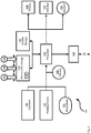
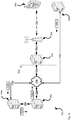
- system 50 comprises a portable electronic device 54, at least one intermediation server 58 and at least one push server 59, which can be located behind a firewall 60.
- a wireless base station 62 interconnects electronic device 54 and push server 59.
- a backhaul link 66 interconnects base station 62 with push server 59.
- At least one bearer path 70 typically wireless, can be used to interconnect base station 62 with electronic device 54.
- bearer path 70 can be based on one or more of Global System for Mobile communications (GSM), General Packet Radio Service (GPRS), Enhanced Data Rates for GSM Evolution (EDGE), the Third-generation mobile communication system (3G), Evolution-Data Optimized (EVDO), Institute of Electrical and Electronic Engineers (IEEE) 802.11 (WiFi) or other wireless protocols.
- GSM Global System for Mobile communications
- GPRS General Packet Radio Service
- EDGE Enhanced Data Rates for GSM Evolution
- 3G Third-generation mobile communication system
- EVDO Evolution-Data Optimized
- IEEE 802.11 WiFi
- Push server 59 is also connected to a network 74 via another backhaul link 67.
- Network 74 can be any type of network that can deliver content to device 54.
- network 74 is the Internet and connects to intermediation server 58 via a backhaul link 78.
- Intermediation server 58 connects to an originating content server 82 by another backhaul link 86.
- electronic device 54 can be any type of computing device that can be used in a self-contained manner and to interact with content available over network 74. Interaction includes displaying of information on electronic device 54 as well as to receive input at electronic device 54 that can in turn be sent back over network 74. It should be emphasized that the structure in Figure 2 is purely exemplary, and contemplates a device that can be used for both wireless voice (e.g. telephony) and wireless data (e.g. email, web browsing, text) communications. In a present embodiment, electronic device 54 is a portable electronic device with the combined functionality of a personal digital assistant, a cell phone, and an email paging device.
- variants on device 54 can include a palm top computer or laptop computer with a reduced screen such as an ASUS EEE from ASUSTek Computer Inc. of Taiwan.
- variants on device 54 can include a personal computer or a laptap computer).
- Many known cellular telephone models, or variants thereof, are suitable for the present embodiment.
- Device 54 thus includes a plurality of input devices which in a present embodiment includes a keyboard 100, a pointing device 102, and a microphone 104.
- Pointing device 102 can be implemented as a track wheel, trackball or the like. Other input devices, such as a touch screen are also contemplated.
- Input from keyboard 100, pointing device 102 and microphone 104 is received at a processor 108.
- Processor 108 is configured to communicate with a non-volatile storage unit 112 (e.g. Erasable Electronic Programmable Read Only Memory (“EEPROM”), Flash Memory) and a volatile storage unit 116 (e.g. random access memory (“RAM”)).
- EEPROM Erasable Electronic Programmable Read Only Memory
- RAM random access memory
- Programming instructions that implement the functional teachings of device 54 as described herein are typically maintained, persistently, in non-volatile storage unit 112 and used by processor 108 which makes appropriate utilization of volatile storage 116 during the execution of such programming instructions.
- Processor 108 in turn is also configured to control a speaker 120, a display 124, and an indicator 125.
- Processor 108 also contains at least one network interface 128, which are implemented in a present embodiment as radios configured to communicate over bearer path 70.
- interface(s) 128 is (are) configured to correspond with the network architecture that defines a particular bearer path 70. It should be understood that in general a wide variety of configurations for device 54 are contemplated.
- device 54 is also configured to maintain a unique device identifier 134, a dashboard application 136, and an application 138 for checking a destination location 140, for example in non-volatile storage 112 and/or a cache, for data change notifications 139 received from intermediation server 58, as will described below.
- destination location 140 can comprise a portion of non-volatile storage 112 and/or a cache allocated for storing data change notifications.
- Destination location hence comprises at least one of a location in non-volatile storage 112 (and/or any other suitable memory device), and a location in a memory structure such a folder for storing data change notifications.
- Device identifier 134 represents a unique absolute identifier of device 54.
- Exemplary device identifiers can include, but are not limited to, an International Mobile Equipment Identity (IMEI) identifier, or a BlackBerryTM PIN as commonly employed in BlackBerryTM devices from Research In Motion Inc., Waterloo, Ontario Canada.
- IMEI International Mobile Equipment Identity
- BlackBerryTM PIN as commonly employed in BlackBerryTM devices from Research In Motion Inc., Waterloo, Ontario Canada.
- Other exemplary device identifiers will now occur to those skilled in the art. It is thus presently preferred that identifier 134 is absolute, non-changeable and non-transferrable, being specifically assigned to the hardware of device 54.
- Processor 108 is also configured to execute dashboard application 136, which is enabled to monitor data 90 at originating content server 82 and can comprise in a data structure for monitoring data 90.
- dashboard application 136 can cause device 54 to transmit a request for data 90 to push server 59, which passes the request to originating content server 82, which returns data 90, or a subset thereof, to device 54.
- this process is bandwidth intensive, especially when dashboard application 236 is frequently refreshed, as can be desired in some embodiments.
- originating content server 82 can comprise an auctioning service where items are bought and sold on-line: when a device 54 (and/or an associated device) has caused bids to be placed on items being auctioned, it can be desirable to request and receive data relating to bids and/or bidding, for example number of items bid on, number of items won, number of items being watched, number of items lost, etc.
- dashboard application 136 comprises a browser application that can refresh automatically and/or on request, with data received from originating content server 82 comprising browser data and/or updates to browser data, including but not limited to data that can be displayed in HTML (hypertext markup language) format.
- HTML hypertext markup language
- changes to data 90 can occur at originating content server 82 that may not result in a visual change to dashboard application 136.
- a visual change to data in dashboard application 136 is not readily apparent.
- it can be desired to indicate when changes have occurred to data 90 without implementing the bandwidth intensive process of requesting and receiving data 90 and/or changes to data 90.
- data change notifications 139 can be received from intermediation server 58 and stored in a destination location, for example, in a memory structure stored in non-volatile storage 112.
- Application 138 is enabled to check the destination location for data change notifications 139 and in response control indicator 125 to indicate that a change has occurred to data 90, as will be described below.
- application 138 can be embedded in dashboard application 136.
- dashboard application 136 comprises a browser application running HTML code
- application 138 can comprise a JavaTM applet embedded in the HTML code.
- application 138 can be a standalone application.
- Processor 108 is configured to access configuration file 136 in order to establish initial settings for one or more applications, including dashboard application 136 and/or application 138, as well as to define any relevant communication gateways on network 74 that correspond to each of those applications. While a BlackBerryTM computing environment is not required to implement the present teachings, where a BlackBerryTM computing environment is used to implement device 54, then configuration file 138 can be implemented as a BlackBerryTM Service Book or as one or more specific entries within a BlackBerryTM Service Book.
- Processor 108 is also configured to receive input from keyboard 100 relative to dashboard application 136 and to generate graphical interfaces on display 124. Processor 108 is further configured to send and receive data/requests/messages associated with dashboard application 136, via network 74 and bearer path 70, as will be discussed further below.
- Device 54 also includes a battery 144 or other power supply. Battery 144 provides power to components within device 54.
- Indicator 125 can comprise any suitable indicator for indicating that a change has occurred to data 90, including but not limited to at least one of a visual indicator, an aural indicator, a mechanical indicator, a vibrating indicator, an LED (light emitting diode), a speaker, and a virtual indicator at display device 124.
- indicator 125 can be combined with speaker 120 and/or display 124.
- indicator 125 can comprise a virtual indicator displayed, for example, within a representation of dashboard application 136 and/or application 138 and/or a combination.
- indicator 125 can comprise a portion of a data structure, for example, a data structure storing dashboard application data displayed at display 124 in a representation of dashboard application 136.
- indicator 125 can comprise an icon in the representation of dashboard application 136.
- intermediation server 58 can be based on any well-known server environment including a module that houses one or more central processing units 208, volatile storage (e.g. random access memory) 216, non-volatile storage 212 (e.g. hard disk devices) and at least one network interface 228 to enable intermediation server 58 to communicate over network 74 and with originating content server 82.
- intermediation server 58 can be a Sun Fire V480 from Sun Microsystems, Inc. of Palo Alto Calif., running a UNIX operating system, and having four central processing units each operating at about nine-hundred megahertz and having about sixteen gigabytes of random access memory.
- this particular server is merely exemplary, and a vast array of other types of computing environments for server 58 is contemplated.
- Intermediation server 58 is enabled to determine that data 90 at originating content server 82 has changed, and in response generate and transmit data change notifications 139 to device 54, via push server 59. As such, in some embodiments, intermediation server 58 is enabled to request data 90 and/or a subset of data 90 from originating content server 82. By processing subsequently received versions of data 90 and/or a subset of data 90, intermediation server 58 can determine when changes have occurred to data 90. Alternatively, originating content server 82 can monitor data 90 and transmit a notification to intermediation server 58, which then determines that data 90 has changed by processing the notification.
- Intermediation server 58 maintains a copy of device identifier 134, and is configured to send data change notification 129 that are addressed using device identifier 134, to device 54.
- Push server 59 can be based on the same or different computing environment as intermediation server 58, such as on any well-known server environment including a module that houses one or more central processing units, volatile storage (e.g. random access memory), non-volatile storage (e.g. hard disk devices) and at least one network interface to enable push server 59 to communicate over network 74 and with device 54.
- intermediation server 58 can be a Sun Fire V480 from Sun Microsystems, Inc. of Palo Alto Calif., running a UNIX operating system, and having four central processing units each operating at about nine-hundred megahertz and having about sixteen gigabytes of random access memory.
- this particular server is merely exemplary, and a vast array of other types of computing environments for server 58 is contemplated.
- Push server 59 also maintains a copy of device identifier 134, and is configured to send data change notification 129 and messages that are addressed using device identifier 134, to device 54.
- Push server 59 and device 54 are thus complementary to each other in that device identifier 134 is used by Push server 59 to send data change notifications 139 and messages to device 54. While a BlackBerryTM computing environment is not required to implement the present teachings, where a BlackBerryTM computing environment is used to implement system 50, then intermediation server 58 can be implemented as a "Relay" server that is specific to a BlackBerryTM computing environment.
- Originating content server 82 can be based on the same or different computing environment as intermediation server 58. Originating content server 82 is enabled to maintain data 90, and to communicate with intermediation server 58. It is appreciated that in some embodiments, originating content server 82 can further communicate with any suitable number of computing device, which can interact with originating content server 82 to cause data 90 to change. In exemplary non-limiting embodiments, originating content server 82 can comprise an auction service, and hence data can be received from various computing devices, including but not limited to device 54, indicative of items that are to be auctioned, bids on items, and the like. Hence data 90 can change frequently based on how often bids are received and the items to be auctioned increase or decrease.
- dashboard application 136 only provides a small subset of data 90, for example the subset of data 90 that includes items associated with an account associated with device 54 and/or a user of device 54, including items being sold and/or bid on by a user of device 54.
- Figure 4 depicts a method 400 for propagating data change notifications.
- method 400 is performed using system 50.
- method 400 can be implemented in device 54.
- the following discussion of method 400 will lead to a further understanding of system 50 and its various components.
- system 50 and/or method 50 can be varied, and need not work exactly as discussed herein in conjunction with each other, and that such variations are within the scope of present embodiments.
- data change notification 139 is received at device 54 from intermediation server 58, data change notification 139 comprising an indication that a change has occurred to data 90 at originating content server 82. It is understood that data change notification 139 is transmitted to device 54 without a request for data change notification 139 being transmitted to intermediation server 58. In other words, data change notification 139 is pushed to device 54.
- data change notification 139 is stored at destination location 140, for example as depicted in Fig. 5.
- Fig. 5 is substantially similar to Fig. 1 with like elements having like numbers, however destination location 140 and indicator 125 are depicted in device 54, though it is understood that device 54 further comprises the elements depicted in Fig.2 . It is understood that device 54 is enabled to determine data change notifications 139 indicate changes to data 90, and further enabled to store data change notifications 139 at destination location 140.
- destination location 140 is checked for data change notifications.
- application 138 when processed, can check destination location 140 for data change notifications.
- indicator 125 is controlled to indicate that a change has occurred to data 90. Otherwise blocks 430 to 440 repeat until data change notification 139 is found.
- indicator 125 can also be controlled to cease indicating that a change has occurred to data 90. For example, after a given period of time and/or after receipt of input data from an input device at device 54, indicator 125 can be turned off.
- blocks 430 to 450 are implemented in application 138 and/or dashboard application 136 when application 138 is embedded in dashboard application 138.
- method 400 can repeat any suitable number of times to indicate a plurality of changes to data 90.
- control of indicator 125 can be customized based on data in data change notification 139.
- indicator 125 can be controlled to indicate that a change has occurred to a watched item.
- indicator 125 can be controlled to indicate that a change has occurred to an item that has been bid on.
- Figure 6 depicts a method 600 for propagating data change notifications to a computing device.
- method 600 is performed using system 50.
- method 600 can be implemented in intermediation server 58.
- the following discussion of method 600 will lead to a further understanding of system 50 and its various components.
- system 50 and/or method 50 can be varied, and need not work exactly as discussed herein in conjunction with each other, and that such variations are within the scope of present embodiments.
- intermediation server 58 determines that data 90 at originating content server 82 has changed.
- block 610 can be implemented by receiving, from originating content server 82 at intermediation server 58, a notification that data 90 has changed.
- block 610 can be implemented by intermediation server 58 requesting data 90, and/or a subset thereof, at least twice from originating content server 82 comparing each instance of data 90 and/or the subset. When each instance is different, intermediation server 58 determines that a change has occurred to data 90.
- Data change notification 139 is generated and transmitted to device 54, which will be received at device 54 within method 400, as described above.
- Data change notification 139 comprises data indicative that a change has occurred to data 90, and can, in background examples, include data indicative of changes to data 90 associated with device 54.
- data change notification 139 is transmitted to push server 58, which in turn pushes data change notification 139 to device 54.
- method 600 can be repeated any suitable number of times. For example, to provide near real-time data, method 600 can be repeated at least several times per minute.
- intermediation server 58 can be configured as a proxy server for device 54, in that intermediation server 58 requests browser data that could be requested by device 54 to display data 90, and/or a subset thereof, in a browser application.
- Push data computing environments can generally enable a suite of services that content providers and administrators of the push-data computing environment to manage the pushing of data to client applications running on devices such as BlackBerryTM devices.
- System 50 will hence enabled allow content providers, for example as represented by originating content server 82, to push near real time data to client applications on devices.
- system 50 can enable delivery of data through a secure existing infrastructure, such as that represented by firewall 60 and push server 59.
- Content providers are further enabled to push the application data to both enterprise and retail device users via a service book such as an ICS (Internet Connection Sharing) service book associated with a BlackBerryTM device.
- Push-data Services can also enable a reliable secure set of services that will enable content provider applications to manage subscription to push-data services.
- originating content server 82 comprises an auction service provided by a content provider.
- platform notifications e.g. notification of changes to data 90
- events such as the ending of a listing or the creation of a transaction within the auction service.
- Platform notifications are not identical in intent, or content, to email messages that buyers and sellers might get when an item is listed, bid on, or purchased. However, they can contain some of the same data that appears in those messages.
- platform notifications for some content provider auction services use an asynchronous style of operation in which the data is pushed from originating content server 82 when it is available. That is, when you notification preferences are set and the content provider is provided with URLs (uniform resource locators), email addresses or the like, then originating content server 82 delivers notifications to the associated locations as events occur.
- URLs uniform resource locators
- platform notifications can be pushed to intermediation server 58 where the platform notification can be converted to a PAP (Push Access Protocol) message (i.e. data change notification 139) and then sent to data push infrastructure (i.e. push server 59).
- PAP Push Access Protocol
- push server 59 then further pushes the data change notification 139 to the device 54.
- originating content server 82 comprises a server side component dealing with platform notification APIs of the content provider.
- a platform notification API deals with event handling and generates platform notifications (which can comprise SOAP (Simple Object Access Protocol) responses).
- intermediation server 58 comprises a push proxy, which can be hosted either by the content provider or an entity associated with push server 58. It is appreciated that intermediation server 58 can be combined with one of originating content server 82 and push server 62. In any event, intermediation server 58 receives the platform notifications from originating content server 82 and remodels data as a PAP message according to what is processable by device 54, e.g. based on templates. The PAP message (data change notification 139) is then pushed to push server 59.
- intermediation server 58 can comprise a stateless proxy component that does not require any sort of capacity or load planning from the content provider or the push-data infrastructure.
- intermediation server 58 can subscribe to platform notifications from originating content server 82 using the platform notification API, for example via an attribute SetNotificationPreferences; preferences already set can be checked with a GetNotificationPreferences attribute.
- the platform notification usage can be monitored with a GetNotificationsUsage attribute.
- push server 59 can comprise at least one enterprise server, such as BlackBerryTM Enterprise Servers that are hosted and maintained by an enterprise associated with device 54.
- Push server 59 is generally enabled for queuing of alerts, acknowledgements and actual push to device 54. The details are available above.
- Application 138 comprises a component that listens for incoming notifications (e.g. data change notifications 139) by checking destination location 140.
- Application 138 can be deployed as a library in dashboard application 136.
- originating content server 82 comprises an auction service
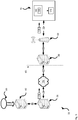
- Fig. 7 which is substantially similar to Fig. 1 , with like elements having like numbers.
- a user logs into originating content server 82 and bids on an item.
- the bid can be placed via a browser and/or an auction client, which can include but is not limited to dashboard application 136. It is assumed that after at least one successful bid attempt, the user is outbid by another user. Being outbid triggers an outbid notification from originating content server 82 which can comprise a SOAP message 739 which contains a field ⁇ externalUserData> which comprises a PIN (product identification number) of device 54 so that data change notification 139 can be pushed to device 54. SOAP message 739 is pushed to the intermediation server 58, and contains.
- Intermediation server 58 receives SOAP message 739 and based on a template extract data from SOAP message 139 to form a PAP message. It can also extracts the field value of ⁇ externalUserData> which was set during a SetNotificationPreferencesRequest event for an authentication token. The value of ⁇ externalUserData> is extracted, decrypted if encrypted, and used to set an address-value in the PAP message, which can include the PIN. Once the PAP message is formed, it is pushed on to push server 59 as data change notification 139.
- Push server 59 then pushes data change notification 139 to device 54 via the PIN, or any other suitable data.
- Push server 59 can send a transport level acknowledgement to intermediation server 58.
- Device 54 listens for message on an identified port receives data change notification 139.
- An acknowledgment can be sent to push server 59, which can in turn send an acknowledgement to intermediation server 58 (and in some embodiments originating content server 82).
- application 138 which can comprise a JAVA applet in dashboard application 136, listens for incoming data change notifications by checking destination location 140.
- destination location 140 comprises a listening module in application 138 and/or dashboard application 136.
- a JavaScript callback is called which in turn updates dashboard application 136.
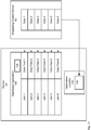
- FIG. 13 depicts a schematic of an implementation of dashboard application 136 with application 138 embedded therein, at device 54, along with destination location 140.
- Fig. 13 further depicts originating content server 82. While Fig. 3 does not depict links between device 54 and originating content server 82, as in Fig. 1 , it is appreciated that device 54 and originating content server 82 can communicate via the previously described links. Furthermore, while not all elements of device 54 and originating content server 54 are depicted, it is appreciated that that all elements previously described are present and device 54 and originating content server 82.
- dashboard application 136 comprises Link 1, Link 2...Link 6 (generically a link and collectively links), with each link being associated with a respective Data Field 1, Data Field 2...Data Field 6 (generically a data field and collectively data fields). Each data field corresponds to Data 1, Data 2...Data 6 stored at originating content server 82. It is appreciated that data stored at originating content server 82 changes, as described above, for example when originating content server 82 comprises an auction service and Data 1, Data 2...Data 6 correspond to items, bids and the like associated device 54 and/or a user thereof.
- a link when a link is activated (for example via an input device), data for the corresponding data field is retrieved from originating content server 82 and stored in the corresponding data field, as represented by the respective arrows between data at originating content server 82 and each data field.
- activation of a link further causes a list of details of the corresponding data field to be retrieved from originating content server 82, such as a corresponding list of items and/or bids of interest, when originating data server 82 comprises and auction service.
- indicator 125 referred to previously with reference to Fig. 2 comprises a virtual indicator in the form of indication 1301.
- data change notification 139 also can comprise the data that has changed (e.g. Data 4 as depicted) and the data received in data change notification 139 is stored in the respective Data Field 4 in background examples.
- application 138 also causes the behaviour of dashboard application 136 to change: when Link 4 is activated, Data 4 is retrieved from destination location 140 rather than originating content server 82 in background examples.
- This approach to notifications generally reduces overall traffic between device 54 and originating content server 82, as well in the links and networks there between, as the approach obviates the need for requests/responses to obtain data updates.
- the data change notification 139 is representative of a state change of data stored at originating content server 82, as well as a state change to data stored in dashboard application 136: for example, in the implementation described with reference to Figs. 12 and 13 , Data Field 4 has undergone a state change as the data stored therein changes.
- the indication 1301 denotes both a change in activity/new activity, and that there is no need to make another network call to fetch the data stored therein.
- Present embodiments also serve to identify which section of dashboard application 136 recently had activity. From a user perspective, it can be appreciated that a user of device 54, wishes to monitor, for example, his/her items, bids etc. via dashboard application 136, again reverting to the non-limiting example of originating content server 82 comprising an auction service. However, the user can be busy with work, family etc., and may not be able to follow up on bids in a timely fashion. Assuming a competing bid was recently made on an item, data change notification 139 can indicate that the competing bid was placed and either explicitly or inherently indicating that the user was outbid. By viewing indicator 1301 at dashboard application 136, the user he/she has been outbid on one of the items without opening an outbid items list.
- another data change notification 139 can be received indicating that an item has been won, and indicator 1301 at dashboard application 136 is updated accordingly by application 138.
- the user is always updated on which data in dashboard application 136 is the newest, without the dashboard application 136 having to be completely refreshed.
- originating content server 82 can monitor when e-mail notifications are transmitted and how often e-mail notifications lead to a retrieval of details of an associated event at originating content server 82 are retrieved: if details are rarely retrieved (e.g. below a threshold number), then the data change notifications 139 for related events are not transmitted.
- application 138 can interface with an e-mail application (not depicted) at device 54 and determine if there are unread notifications pertaining to data change notification 139 and hence prevent indicator 1301 from being provided and/or controlled.
- application 139 can determine that there is no interest in data change/data update and either remove indicator 1301 after a given time period and/or remove indicator 1301 from dashboard application 136 when it is closed and reopened.
- data associated with data change notification 139 can have a short life.
- a data change notification 139 associated with a watched item whose auction is ending within a given time period can comprise data representative of the given time period.
- indicator 1301 can expire after the given time period, for example be removed from dashboard application 136, as the data associated with it has expired.
- FIG. 8 depicts a specific exemplary representation 800 of dashboard application 136 displayed at display 124.
- Representation 800 comprises n identifying header 801, any suitable number of virtual buttons for triggering interactions with originating content server 82 (as depicted, "Search”, “My Auctions”, and “Sign Out”).
- a body 802 includes a plurality of lines, each line comprising a link to associated data in the form of descriptive text providing information on numbers "BEST OFFERS", items being bid on (“BIDDING ON”), items “WON”, auctions being won but that aren't yet complete (“WINNING ON”), items being watched (“WATCHED”), and number of items "LOST”.
- each line in body 902 can comprise an HTML link to data available via originating content server 82 corresponding to the text in each line.
- Body 802 can include any suitable type of data and in some embodiments can be configurable. As depicted in Fig. 8 , data change notification 139 has not yet been found, and it is assumed that only one item is being bid on, which is currently the winning bid.
- representation 800 is updated as in Fig. 9 as data change notification 139 is determined to indicate that the user has been outbid on an item.
- the number next to "WINNING ON” decreases to "0" (as depicted), and an indicator in the form of an icon 901 appears next to the number next to "WINNING ON” to indicate that the data on this line has changed.
- indicator 125 comprises icon 901.
- the JavaScript call-back (e.g. application 138) ensures content in representation 800 does not have to be reloaded to view the latest changes.
- dashboard application 136 comprises a browser and hence data displayed in dashboard application 136 comprises browser data such as HTML data and/or a webpage, then the page does not have to be reloaded to get the updates for the browser data.
- the design pattern for the JavaScript callback is inversion of control: i.e. if a new event is triggered then the JavaScript callback calls another module, instead of the parent module polling for information related to the event.
- the flow of information is hence from JAVA to JavaScript. This asynchronous update keeps device 54 updated on activities at originating content server 82, that are related to dashboard application 136/ browser data which might effect a future interaction decision.
- the functionality of the intermediation server 58 can be summarized as follows:
- a non-limiting sale notification example of a PAP payload template is provided as follows:
- Figure 10 shows system 50a which is a variation on system 50 and like elements in system 50a include like references to their counterparts in system 50, except followed by the suffix "a".
- originating content server 82 has been replaced by a backup server 1082 in communication with a data storage device 1090 via network 74a (or any other suitable network) and suitable backhaul links 1092 and 1094.
- Each of backup server 1082 and storage server 1090 can be based on the same or different computing environment as intermediation server 58 as described above.
- storage server 1090 can comprise a server of an enterprise that stores data associated with the enterprise, and backup server 1082 can comprise a server associated with a remote data storage service. It is appreciated that in some embodiments, backups can occur nightly, and/or hourly, and/or every 15 minutes by transmitting data 1095 to server 1082. Furthermore, it is understood that after an initial seeding event, in which all data stored at server 1090 is copied to backup server 1082, then data 1095 transmitted in a backup/synchronization event can comprise a delta between the data stored at server 1090 and the data stored at server 1082. It is appreciated that data 1095 can be transmitted via a plurality of packets over a period of time such that a backup/synchronization event occurs in a series of smaller transfers.
- device 54a can comprise an application for monitoring backups/synchronizations so that the progress of a backup/synchronization event can be monitored.
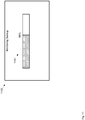
- a non-limiting embodiment of a representation 1100 of such a monitoring application is provided in Fig. 11 , representation 1100 displayed on a display at device 54a, similar to display 124 described above.
- Representation 1100 comprises an indicator 1101 which indicates changes to data stored at backup server 1082, and specifically the progress of a backup/synchronization event between server 1090 and server 1082.
- backup server 1082 is enabled to push messages 1039 to intermediation server 58a, push messages 1039 comprising data indicative of the progress of a backup/synchronization event. Such progress can be determined as in a first transfer of data to server 1082, server 1090 can indicate the total amount of data 1095 that is to be backed up.
- intermediation server 58a formats the payload of data change notifications 139a to indicate the progress of the backup/synchronization event using the payload from messages 1039 and pushes data change notifications 139a to push server 59a, which in turn pushes data change notifications 139a to device 54a.
- Data change notifications 139a are monitored by an application for monitoring data change notices as described above and updates to the representation 1100 are provided without having to request progress data from server 1082. In this manner, the progress of the backup/synchronization event can be monitored without having to do a push pull /request response / page reload, and using existing push infrastructure as represented by push server 59a.
- any suitable number messages 1039 can be pushed to intermediation server 58a, at any suitable frequency. Furthermore, monitoring of backup/synchronization events can be controlled by transmitting control data to server 1082 from device 54a indicating whether messages 1039 are to be pushed or not.
- devices 54, 54a, and servers 58, 58a, 59, 59a, 82, 1082 and 1090 can be implemented using pre-programmed hardware or firmware elements (e.g., application specific integrated circuits (ASICs), electrically erasable programmable read-only memories (EEPROMs), etc.), or other related components.
- ASICs application specific integrated circuits
- EEPROMs electrically erasable programmable read-only memories
- the functionality of devices 54, 54a, and servers 58, 58a, 59, 59a, 82, 1082 and 1090 can be achieved using a computing apparatus that has access to a code memory (not shown) which stores computer-readable program code for operation of the computing apparatus.
- the computer-readable program code could be stored on a computer readable storage medium which is fixed, tangible and readable directly by these components, (e.g., removable diskette, CD-ROM, ROM, fixed disk, USB drive).
- the computer-readable program code could be stored remotely but transmittable to these components via a modem or other interface device connected to a network (including, without limitation, the Internet) over a transmission medium.
- the transmission medium can be either a non-wireless medium (e.g., optical and/or digital and/or analog communications lines) or a wireless medium (e.g., microwave, infrared, free-space optical or other transmission schemes) or a combination thereof.
Claims (8)
- Verfahren zum Verbreiten von Datenänderungsbenachrichtigungen, wobei das Verfahren in einer Computervorrichtung (54) implementiert werden kann, die über ein Netzwerk mit einem Intermediationsserver (58) kommuniziert, wobei der Intermediationsserver (58) mit einem originierenden Inhaltsserver (82) verbunden ist, der dafür konfiguriert ist, Daten (90) zu verwalten, die mehrere Datenelemente (Daten 1 - Daten 6) enthalten, wobei das Verfahren Folgendes umfasst:- Ausführen, durch einen Prozessor (108) der Computervorrichtung (54), einer ersten Anwendung (136), die dafür konfiguriert ist, Daten (90) von dem originierenden Inhaltsserver (82) anzufordern und zu empfangen;- Empfangen (410), durch eine Netzwerkkommunikationsschnittstelle (128) der Computervorrichtung (54), von Datenänderungsbenachrichtigungen (139) von dem Intermediationsserver (58) an der Computervorrichtung (54), ohne dass eine Anforderung für die Datenänderungsbenachrichtigungen (139) von der Computervorrichtung (54) zu dem Intermediationsserver (58) gesendet wird, wobei die Datenänderungsbenachrichtigungen (139) Hinweise umfassen, dass Änderungen an Datenelementen der Daten (90) stattgefunden haben, die auf dem originierenden Inhaltsserver (82) verwaltet werden;- Speichern (420) der Datenänderungsbenachrichtigungen (139), die von dem Intermediationsserver (58) kommend in der Computervorrichtung (54) empfangen werden, an einer Zielposition (140) in einer Speicherstruktur, die in einem nicht-flüchtigen Speicher (112) und/oder einem Cache in der Computervorrichtung (54) gespeichert wird;- Ausführen, durch den Prozessor (108) der Computervorrichtung (54), einer zweiten Anwendung (138), die dafür konfiguriert ist, die Zielposition (140) in der Speicherstruktur, die in dem nicht-flüchtigen Speicher (112) und/oder dem Cache der Computervorrichtung (54) gespeichert ist, auf Datenänderungsbenachrichtigungen (139) zu überprüfen (430), die von dem Intermediationsserver (58) kommend empfangen wurden; und- Steuern (450), wenn eine jeweilige Datenänderungsbenachrichtigung (139) durch die zweite Anwendung (138) an der Zielposition (140) in der Speicherstruktur, die in dem nicht-flüchtigen Speicher (112) und/oder dem Cache der Computervorrichtung (54) gespeichert ist, gefunden wird, die einen Hinweis umfasst, dass eine Änderung an einem gegebenen Datenelement der Daten (90), die in dem originierenden Inhaltsserver (82) verwaltet werden, stattgefunden hat, eines Indikators (125), um anzuzeigen, dass eine Änderung an dem gegebenen Datenelement der Daten (90), die in dem originierenden Inhaltsserver (82) verwaltet werden, stattgefunden hat;wobei die erste Anwendung (136) mehrere Links (Link 1 - Link 6) und mehrere Datenfelder (Datenfeld 1 - Datenfeld 6) enthält, wobei jeder der mehreren Links (Link 1 - Link 6) mit einem jeweiligen Datenfeld der mehreren Datenfelder (Datenfeld 1 - Datenfeld 6) verknüpft ist, und jedes Datenfeld einem jeweiligen Datenelement (Daten 1; Daten 2; Daten 3; Daten 4; Daten 5; Daten 6) der Daten (90), die in dem originierenden Inhaltsserver (82) verwaltet werden, entspricht; und
wobei, wenn ein jeweiliger Link (Link 4) der mehreren Links (Link 1 - Link 6) über eine Eingabevorrichtung der Computervorrichtung (54) aktiviert wird und die zweite Anwendung (138) eine Datenänderungsbenachrichtigung (139) findet, die an der Zielposition (140) gespeichert ist, die anzeigt, dass die Daten (Daten 4) für das jeweilige Datenfeld (Datenfeld 4), das mit dem jeweilige Link (Link 4) verknüpft ist, geändert wurden, das jeweilige Datenelement (Daten 4) für das jeweilige Datenfeld (Datenfeld 4), das mit dem jeweiligen Link (Link 4) verknüpft ist, aus dem originierenden Inhaltsserver (82) abgerufen wird, und das aus dem originierenden Inhaltsserver (82) abgerufene Datenelement (Daten 4) in dem jeweiligen Datenfeld (Datenfeld 4) gespeichert wird, das mit dem jeweiligen Link (Link 4) verknüpft ist. - Verfahren nach Anspruch 1, wobei die erste Anwendung (136) eine Browser-Anwendung umfasst, die einen HTML-Code abarbeitet, und dafür konfiguriert ist, mit Daten aufgefrischt zu werden, die von dem originierenden Inhaltsserver (82) kommend empfangen wurden.
- Verfahren nach Anspruch 2, wobei die zweite Anwendung (138) in die erste Anwendung (136) eingebettet ist und ein Java-Applet enthält, das in den HTML-Code der ersten Anwendung (136) eingebettet ist.
- Verfahren nach Anspruch 3, wobei das Überprüfen (430) der Zielposition (140) in der Speicherstruktur, die in dem nicht-flüchtigen Speicher (112) gespeichert ist, auf die Datenänderungsbenachrichtigungen durch die zweite Anwendung (138) über das Java-Applet in der Computervorrichtung (54) erfolgt.
- Verfahren nach Anspruch 2, 3 oder 4, wobei der Indikator (125) ein Icon enthält, das innerhalb der Darstellung der ersten Anwendung (136) angezeigt wird, dergestalt, dass nur der Indikator (125) innerhalb der HTML-Daten der Darstellung der ersten Anwendung (136) aktualisiert wird und nicht alle HTML-Daten der Darstellung der ersten Anwendung (136).
- Verfahren nach Anspruch 1, wobei der Indikator (125) des Weiteren so gesteuert wird, dass er nach einem gegebenen Zeitraum verfällt.
- Verfahren nach Anspruch 1, wobei der Indikator (125) mindestens eines von Folgendem umfasst: einen visuellen Indikator, einen akustischen Indikator, einen mechanischen Indikator, einen Vibrationsindikator, eine LED, einen Lautsprecher, und eine Darstellung des Indikators (125) in einer Anzeigevorrichtung (124), die der Computervorrichtung (54) zugeordnet ist.
- Computervorrichtung (54) zum Verbreiten von Datenänderungsbenachrichtigungen, die Folgendes umfasst:einen Prozessor (108), der mit einer Speichervorrichtung (140) verbunden ist, und eine Kommunikationsschnittstelle (128), wobei die Kommunikationsschnittstelle (128) dem Kommunizieren mit einem Intermediationsserver (58) über ein Netzwerk dient, wobei der Prozessor (108) befähigt ist, beliebige der Schritte des Verfahrens der Ansprüche 1 bis 6 zu implementieren.
Priority Applications (2)
| Application Number | Priority Date | Filing Date | Title |
|---|---|---|---|
| EP10154023.5A EP2369496B1 (de) | 2010-02-18 | 2010-02-18 | Verfahren, System und Vorrichtung zur Verbreitung von Datenänderungsmitteilungen |
| CA2731822A CA2731822C (en) | 2010-02-18 | 2011-02-15 | Method, system and apparatus for propagating data change notifications |
Applications Claiming Priority (1)
| Application Number | Priority Date | Filing Date | Title |
|---|---|---|---|
| EP10154023.5A EP2369496B1 (de) | 2010-02-18 | 2010-02-18 | Verfahren, System und Vorrichtung zur Verbreitung von Datenänderungsmitteilungen |
Publications (2)
| Publication Number | Publication Date |
|---|---|
| EP2369496A1 EP2369496A1 (de) | 2011-09-28 |
| EP2369496B1 true EP2369496B1 (de) | 2018-11-21 |
Family
ID=42113740
Family Applications (1)
| Application Number | Title | Priority Date | Filing Date |
|---|---|---|---|
| EP10154023.5A Active EP2369496B1 (de) | 2010-02-18 | 2010-02-18 | Verfahren, System und Vorrichtung zur Verbreitung von Datenänderungsmitteilungen |
Country Status (2)
| Country | Link |
|---|---|
| EP (1) | EP2369496B1 (de) |
| CA (1) | CA2731822C (de) |
Families Citing this family (1)
| Publication number | Priority date | Publication date | Assignee | Title |
|---|---|---|---|---|
| CN113420037B (zh) * | 2021-06-27 | 2023-06-27 | 杭州迪普科技股份有限公司 | 资产数据实时变更方法及装置 |
Family Cites Families (8)
| Publication number | Priority date | Publication date | Assignee | Title |
|---|---|---|---|---|
| US7275073B2 (en) * | 2003-05-07 | 2007-09-25 | Good Technology, Inc. | System and method for notifying mobile devices based on device type and network capabilities |
| US7457631B2 (en) * | 2004-02-10 | 2008-11-25 | Research In Motion Limited | Apparatus, and associated method, for facilitating synchronization of databases connected by way of a radio air interface |
| CA2528080A1 (en) * | 2004-07-30 | 2006-01-30 | Research In Motion Limited | Method and apparatus for synchronizing contact data stores |
| ATE386984T1 (de) * | 2004-10-22 | 2008-03-15 | Research In Motion Ltd | Einrichtung und verfahren zum integrieren kontinuierlicher synchronisation an tragbaren endgeräten |
| US7840528B2 (en) * | 2004-10-22 | 2010-11-23 | Research In Motion Limited | System and method for integrating continuous synchronization on a host handheld device |
| US20070112856A1 (en) | 2005-11-17 | 2007-05-17 | Aaron Schram | System and method for providing analytics for a communities framework |
| US8146101B2 (en) * | 2006-04-28 | 2012-03-27 | Research In Motion Limited | Method of processing notifications provided by a routine, and associated handheld electronic device |
| US20090089342A1 (en) * | 2007-09-28 | 2009-04-02 | Research In Motion Limited | Electronic device and method for managing storage of data |
-
2010
- 2010-02-18 EP EP10154023.5A patent/EP2369496B1/de active Active
-
2011
- 2011-02-15 CA CA2731822A patent/CA2731822C/en active Active
Non-Patent Citations (1)
| Title |
|---|
| None * |
Also Published As
| Publication number | Publication date |
|---|---|
| CA2731822C (en) | 2015-06-30 |
| CA2731822A1 (en) | 2011-08-18 |
| EP2369496A1 (de) | 2011-09-28 |
Similar Documents
| Publication | Publication Date | Title |
|---|---|---|
| US8799349B2 (en) | Method, system and apparatus for propagating data change notifications | |
| US9900398B2 (en) | Apparatus and method for context-aware mobile data management | |
| US6868544B2 (en) | Method and system for general-purpose interactive notifications | |
| CN104301373B (zh) | 经由文件共享服务同步的推送通知 | |
| EP1872522B1 (de) | System und verfahren zur ermöglichung von asynchronen anwendungen auf push-basis auf einem drahtlosen gerät | |
| US20030023451A1 (en) | Method and apparatus for identifying privacy levels | |
| US20050038874A1 (en) | System and method for downloading data using a proxy | |
| EP2442532A1 (de) | Technik zur Handhabung von URLs für verschiedene mobile Vorrichtungen, die verschiedene Benutzerschnittstellenplattformen nutzen | |
| TW200826551A (en) | Offline execution of web based applications | |
| EP2146476A2 (de) | Fernzugriff auf informationen auf einem mobilen endgerät von einer internetbrowser-erweiterung aus | |
| EP2146475A1 (de) | Zugriff auf informationen auf einem mobilen endgerät von einem entfernten endgerät aus | |
| CN115004673B (zh) | 消息推送方法、装置、电子设备及计算机可读介质 | |
| CN101156407A (zh) | 用于计划的下载服务的系统结构和方法 | |
| US20050114470A1 (en) | Communications system | |
| JP2006243985A (ja) | メッセージ通知システム及びその方法並びにそれに用いるサーバ | |
| EP1872525B1 (de) | System und verfahren zum entdecken drahtloser mobiler anwendungen | |
| EP2369496B1 (de) | Verfahren, System und Vorrichtung zur Verbreitung von Datenänderungsmitteilungen | |
| JP4252416B2 (ja) | 携帯通信端末、情報提供システム | |
| CN113256240B (zh) | 消息的处理方法、装置和服务器 | |
| US9596199B2 (en) | Enabling and supporting a presence server cache | |
| JP2002328874A (ja) | 電子メールの管理方法と管理装置 | |
| Pilioura et al. | Using Web Services for supporting the users of wireless devices | |
| JP2007206950A (ja) | 情報配信システム、情報配信方法及び情報配信プログラム | |
| US20240152504A1 (en) | Data interaction method, apparatus, and electronic device | |
| US10645597B2 (en) | Message by message tunability of message reliability in a cellular network |
Legal Events
| Date | Code | Title | Description |
|---|---|---|---|
| PUAI | Public reference made under article 153(3) epc to a published international application that has entered the european phase |
Free format text: ORIGINAL CODE: 0009012 |
|
| 17P | Request for examination filed |
Effective date: 20100218 |
|
| AK | Designated contracting states |
Kind code of ref document: A1 Designated state(s): AT BE BG CH CY CZ DE DK EE ES FI FR GB GR HR HU IE IS IT LI LT LU LV MC MK MT NL NO PL PT RO SE SI SK SM TR |
|
| AX | Request for extension of the european patent |
Extension state: AL BA RS |
|
| RAP1 | Party data changed (applicant data changed or rights of an application transferred) |
Owner name: RESEARCH IN MOTION LIMITED |
|
| 17Q | First examination report despatched |
Effective date: 20120120 |
|
| RAP1 | Party data changed (applicant data changed or rights of an application transferred) |
Owner name: BLACKBERRY LIMITED |
|
| RAP1 | Party data changed (applicant data changed or rights of an application transferred) |
Owner name: BLACKBERRY LIMITED |
|
| GRAP | Despatch of communication of intention to grant a patent |
Free format text: ORIGINAL CODE: EPIDOSNIGR1 |
|
| STAA | Information on the status of an ep patent application or granted ep patent |
Free format text: STATUS: GRANT OF PATENT IS INTENDED |
|
| INTG | Intention to grant announced |
Effective date: 20180611 |
|
| GRAS | Grant fee paid |
Free format text: ORIGINAL CODE: EPIDOSNIGR3 |
|
| GRAA | (expected) grant |
Free format text: ORIGINAL CODE: 0009210 |
|
| STAA | Information on the status of an ep patent application or granted ep patent |
Free format text: STATUS: THE PATENT HAS BEEN GRANTED |
|
| AK | Designated contracting states |
Kind code of ref document: B1 Designated state(s): AT BE BG CH CY CZ DE DK EE ES FI FR GB GR HR HU IE IS IT LI LT LU LV MC MK MT NL NO PL PT RO SE SI SK SM TR |
|
| REG | Reference to a national code |
Ref country code: DE Ref legal event code: R079 Ref document number: 602010055221 Country of ref document: DE Free format text: PREVIOUS MAIN CLASS: G06F0017300000 Ipc: G06F0016000000 |
|
| REG | Reference to a national code |
Ref country code: CH Ref legal event code: EP |
|
| REG | Reference to a national code |
Ref country code: IE Ref legal event code: FG4D |
|
| REG | Reference to a national code |
Ref country code: DE Ref legal event code: R096 Ref document number: 602010055221 Country of ref document: DE |
|
| REG | Reference to a national code |
Ref country code: AT Ref legal event code: REF Ref document number: 1068371 Country of ref document: AT Kind code of ref document: T Effective date: 20181215 |
|
| REG | Reference to a national code |
Ref country code: NL Ref legal event code: MP Effective date: 20181121 |
|
| REG | Reference to a national code |
Ref country code: AT Ref legal event code: MK05 Ref document number: 1068371 Country of ref document: AT Kind code of ref document: T Effective date: 20181121 |
|
| PG25 | Lapsed in a contracting state [announced via postgrant information from national office to epo] |
Ref country code: FI Free format text: LAPSE BECAUSE OF FAILURE TO SUBMIT A TRANSLATION OF THE DESCRIPTION OR TO PAY THE FEE WITHIN THE PRESCRIBED TIME-LIMIT Effective date: 20181121 Ref country code: BG Free format text: LAPSE BECAUSE OF FAILURE TO SUBMIT A TRANSLATION OF THE DESCRIPTION OR TO PAY THE FEE WITHIN THE PRESCRIBED TIME-LIMIT Effective date: 20190221 Ref country code: NO Free format text: LAPSE BECAUSE OF FAILURE TO SUBMIT A TRANSLATION OF THE DESCRIPTION OR TO PAY THE FEE WITHIN THE PRESCRIBED TIME-LIMIT Effective date: 20190221 Ref country code: LT Free format text: LAPSE BECAUSE OF FAILURE TO SUBMIT A TRANSLATION OF THE DESCRIPTION OR TO PAY THE FEE WITHIN THE PRESCRIBED TIME-LIMIT Effective date: 20181121 Ref country code: IS Free format text: LAPSE BECAUSE OF FAILURE TO SUBMIT A TRANSLATION OF THE DESCRIPTION OR TO PAY THE FEE WITHIN THE PRESCRIBED TIME-LIMIT Effective date: 20190321 Ref country code: AT Free format text: LAPSE BECAUSE OF FAILURE TO SUBMIT A TRANSLATION OF THE DESCRIPTION OR TO PAY THE FEE WITHIN THE PRESCRIBED TIME-LIMIT Effective date: 20181121 Ref country code: ES Free format text: LAPSE BECAUSE OF FAILURE TO SUBMIT A TRANSLATION OF THE DESCRIPTION OR TO PAY THE FEE WITHIN THE PRESCRIBED TIME-LIMIT Effective date: 20181121 Ref country code: LV Free format text: LAPSE BECAUSE OF FAILURE TO SUBMIT A TRANSLATION OF THE DESCRIPTION OR TO PAY THE FEE WITHIN THE PRESCRIBED TIME-LIMIT Effective date: 20181121 Ref country code: HR Free format text: LAPSE BECAUSE OF FAILURE TO SUBMIT A TRANSLATION OF THE DESCRIPTION OR TO PAY THE FEE WITHIN THE PRESCRIBED TIME-LIMIT Effective date: 20181121 |
|
| PG25 | Lapsed in a contracting state [announced via postgrant information from national office to epo] |
Ref country code: PT Free format text: LAPSE BECAUSE OF FAILURE TO SUBMIT A TRANSLATION OF THE DESCRIPTION OR TO PAY THE FEE WITHIN THE PRESCRIBED TIME-LIMIT Effective date: 20190321 Ref country code: NL Free format text: LAPSE BECAUSE OF FAILURE TO SUBMIT A TRANSLATION OF THE DESCRIPTION OR TO PAY THE FEE WITHIN THE PRESCRIBED TIME-LIMIT Effective date: 20181121 Ref country code: SE Free format text: LAPSE BECAUSE OF FAILURE TO SUBMIT A TRANSLATION OF THE DESCRIPTION OR TO PAY THE FEE WITHIN THE PRESCRIBED TIME-LIMIT Effective date: 20181121 Ref country code: GR Free format text: LAPSE BECAUSE OF FAILURE TO SUBMIT A TRANSLATION OF THE DESCRIPTION OR TO PAY THE FEE WITHIN THE PRESCRIBED TIME-LIMIT Effective date: 20190222 |
|
| PG25 | Lapsed in a contracting state [announced via postgrant information from national office to epo] |
Ref country code: CZ Free format text: LAPSE BECAUSE OF FAILURE TO SUBMIT A TRANSLATION OF THE DESCRIPTION OR TO PAY THE FEE WITHIN THE PRESCRIBED TIME-LIMIT Effective date: 20181121 Ref country code: PL Free format text: LAPSE BECAUSE OF FAILURE TO SUBMIT A TRANSLATION OF THE DESCRIPTION OR TO PAY THE FEE WITHIN THE PRESCRIBED TIME-LIMIT Effective date: 20181121 Ref country code: DK Free format text: LAPSE BECAUSE OF FAILURE TO SUBMIT A TRANSLATION OF THE DESCRIPTION OR TO PAY THE FEE WITHIN THE PRESCRIBED TIME-LIMIT Effective date: 20181121 Ref country code: IT Free format text: LAPSE BECAUSE OF FAILURE TO SUBMIT A TRANSLATION OF THE DESCRIPTION OR TO PAY THE FEE WITHIN THE PRESCRIBED TIME-LIMIT Effective date: 20181121 |
|
| REG | Reference to a national code |
Ref country code: DE Ref legal event code: R097 Ref document number: 602010055221 Country of ref document: DE |
|
| PG25 | Lapsed in a contracting state [announced via postgrant information from national office to epo] |
Ref country code: EE Free format text: LAPSE BECAUSE OF FAILURE TO SUBMIT A TRANSLATION OF THE DESCRIPTION OR TO PAY THE FEE WITHIN THE PRESCRIBED TIME-LIMIT Effective date: 20181121 Ref country code: SM Free format text: LAPSE BECAUSE OF FAILURE TO SUBMIT A TRANSLATION OF THE DESCRIPTION OR TO PAY THE FEE WITHIN THE PRESCRIBED TIME-LIMIT Effective date: 20181121 Ref country code: RO Free format text: LAPSE BECAUSE OF FAILURE TO SUBMIT A TRANSLATION OF THE DESCRIPTION OR TO PAY THE FEE WITHIN THE PRESCRIBED TIME-LIMIT Effective date: 20181121 Ref country code: SK Free format text: LAPSE BECAUSE OF FAILURE TO SUBMIT A TRANSLATION OF THE DESCRIPTION OR TO PAY THE FEE WITHIN THE PRESCRIBED TIME-LIMIT Effective date: 20181121 |
|
| PLBE | No opposition filed within time limit |
Free format text: ORIGINAL CODE: 0009261 |
|
| STAA | Information on the status of an ep patent application or granted ep patent |
Free format text: STATUS: NO OPPOSITION FILED WITHIN TIME LIMIT |
|
| REG | Reference to a national code |
Ref country code: CH Ref legal event code: PL |
|
| 26N | No opposition filed |
Effective date: 20190822 |
|
| PG25 | Lapsed in a contracting state [announced via postgrant information from national office to epo] |
Ref country code: MC Free format text: LAPSE BECAUSE OF FAILURE TO SUBMIT A TRANSLATION OF THE DESCRIPTION OR TO PAY THE FEE WITHIN THE PRESCRIBED TIME-LIMIT Effective date: 20181121 Ref country code: LU Free format text: LAPSE BECAUSE OF NON-PAYMENT OF DUE FEES Effective date: 20190218 Ref country code: SI Free format text: LAPSE BECAUSE OF FAILURE TO SUBMIT A TRANSLATION OF THE DESCRIPTION OR TO PAY THE FEE WITHIN THE PRESCRIBED TIME-LIMIT Effective date: 20181121 |
|
| REG | Reference to a national code |
Ref country code: BE Ref legal event code: MM Effective date: 20190228 |
|
| REG | Reference to a national code |
Ref country code: IE Ref legal event code: MM4A |
|
| PG25 | Lapsed in a contracting state [announced via postgrant information from national office to epo] |
Ref country code: LI Free format text: LAPSE BECAUSE OF NON-PAYMENT OF DUE FEES Effective date: 20190228 Ref country code: CH Free format text: LAPSE BECAUSE OF NON-PAYMENT OF DUE FEES Effective date: 20190228 |
|
| PG25 | Lapsed in a contracting state [announced via postgrant information from national office to epo] |
Ref country code: IE Free format text: LAPSE BECAUSE OF NON-PAYMENT OF DUE FEES Effective date: 20190218 |
|
| PG25 | Lapsed in a contracting state [announced via postgrant information from national office to epo] |
Ref country code: BE Free format text: LAPSE BECAUSE OF NON-PAYMENT OF DUE FEES Effective date: 20190228 |
|
| PG25 | Lapsed in a contracting state [announced via postgrant information from national office to epo] |
Ref country code: TR Free format text: LAPSE BECAUSE OF FAILURE TO SUBMIT A TRANSLATION OF THE DESCRIPTION OR TO PAY THE FEE WITHIN THE PRESCRIBED TIME-LIMIT Effective date: 20181121 |
|
| PG25 | Lapsed in a contracting state [announced via postgrant information from national office to epo] |
Ref country code: MT Free format text: LAPSE BECAUSE OF NON-PAYMENT OF DUE FEES Effective date: 20190218 |
|
| PG25 | Lapsed in a contracting state [announced via postgrant information from national office to epo] |
Ref country code: CY Free format text: LAPSE BECAUSE OF FAILURE TO SUBMIT A TRANSLATION OF THE DESCRIPTION OR TO PAY THE FEE WITHIN THE PRESCRIBED TIME-LIMIT Effective date: 20181121 |
|
| PG25 | Lapsed in a contracting state [announced via postgrant information from national office to epo] |
Ref country code: HU Free format text: LAPSE BECAUSE OF FAILURE TO SUBMIT A TRANSLATION OF THE DESCRIPTION OR TO PAY THE FEE WITHIN THE PRESCRIBED TIME-LIMIT; INVALID AB INITIO Effective date: 20100218 |
|
| PG25 | Lapsed in a contracting state [announced via postgrant information from national office to epo] |
Ref country code: MK Free format text: LAPSE BECAUSE OF FAILURE TO SUBMIT A TRANSLATION OF THE DESCRIPTION OR TO PAY THE FEE WITHIN THE PRESCRIBED TIME-LIMIT Effective date: 20181121 |
|
| PGFP | Annual fee paid to national office [announced via postgrant information from national office to epo] |
Ref country code: FR Payment date: 20230223 Year of fee payment: 14 |
|
| PGFP | Annual fee paid to national office [announced via postgrant information from national office to epo] |
Ref country code: DE Payment date: 20240228 Year of fee payment: 15 Ref country code: GB Payment date: 20240220 Year of fee payment: 15 |