EP2369276A1 - Electrical household appliance for cooling food - Google Patents
Electrical household appliance for cooling food Download PDFInfo
- Publication number
- EP2369276A1 EP2369276A1 EP11157602A EP11157602A EP2369276A1 EP 2369276 A1 EP2369276 A1 EP 2369276A1 EP 11157602 A EP11157602 A EP 11157602A EP 11157602 A EP11157602 A EP 11157602A EP 2369276 A1 EP2369276 A1 EP 2369276A1
- Authority
- EP
- European Patent Office
- Prior art keywords
- insert
- layer
- household appliance
- door
- electrical household
- Prior art date
- Legal status (The legal status is an assumption and is not a legal conclusion. Google has not performed a legal analysis and makes no representation as to the accuracy of the status listed.)
- Withdrawn
Links
- 238000001816 cooling Methods 0.000 title claims abstract description 17
- 235000013305 food Nutrition 0.000 title claims abstract description 17
- 239000000463 material Substances 0.000 claims abstract description 15
- 239000003822 epoxy resin Substances 0.000 claims abstract description 8
- 229920000647 polyepoxide Polymers 0.000 claims abstract description 8
- 230000002787 reinforcement Effects 0.000 claims abstract description 5
- 239000011248 coating agent Substances 0.000 claims description 12
- 238000000576 coating method Methods 0.000 claims description 12
- 238000010438 heat treatment Methods 0.000 claims description 10
- 239000000853 adhesive Substances 0.000 claims description 6
- 230000001070 adhesive effect Effects 0.000 claims description 6
- 238000000034 method Methods 0.000 claims description 5
- 239000003973 paint Substances 0.000 claims description 5
- 239000002184 metal Substances 0.000 claims description 4
- 238000004026 adhesive bonding Methods 0.000 claims description 3
- 239000010410 layer Substances 0.000 description 47
- 238000009413 insulation Methods 0.000 description 4
- 229920005830 Polyurethane Foam Polymers 0.000 description 3
- 239000011496 polyurethane foam Substances 0.000 description 3
- 239000002131 composite material Substances 0.000 description 2
- 230000000694 effects Effects 0.000 description 2
- 239000011152 fibreglass Substances 0.000 description 2
- 230000001681 protective effect Effects 0.000 description 2
- 239000012790 adhesive layer Substances 0.000 description 1
- 238000010276 construction Methods 0.000 description 1
- 230000014509 gene expression Effects 0.000 description 1
- 235000021478 household food Nutrition 0.000 description 1
- 239000011810 insulating material Substances 0.000 description 1
- 239000007769 metal material Substances 0.000 description 1
- 239000004033 plastic Substances 0.000 description 1
- 229920003023 plastic Polymers 0.000 description 1
Images

Classifications
-
- F—MECHANICAL ENGINEERING; LIGHTING; HEATING; WEAPONS; BLASTING
- F25—REFRIGERATION OR COOLING; COMBINED HEATING AND REFRIGERATION SYSTEMS; HEAT PUMP SYSTEMS; MANUFACTURE OR STORAGE OF ICE; LIQUEFACTION SOLIDIFICATION OF GASES
- F25D—REFRIGERATORS; COLD ROOMS; ICE-BOXES; COOLING OR FREEZING APPARATUS NOT OTHERWISE PROVIDED FOR
- F25D23/00—General constructional features
- F25D23/02—Doors; Covers
Definitions
- This invention relates to an electrical household appliance for cooling and storing food.
- a door giving access to a cooled compartment for storing the food is subject to deformation during use.
- the deformation is normally attributable to the temperature difference between the inside and the outside of the compartment. More specifically, the deformation causes the door to change from a substantially flat shape to a shape where it is slightly curved outwards.
- This problem affects mostly, but not only, household food cooling and storing appliances having a single door and where the extension of the door in a first direction (typically the vertical one) is much greater than in the other directions at right angles to the first direction (the effect is much more evident in freezers because the thermal gradient is steeper).
- the door comprises a first face directed towards the outside of the cooling appliance, a second face directed towards the cooled compartment and an outer edge which is interposed between the first and the second face and which extends principally along a closed rectangular line of extension.
- the two long sides of the rectangular outer edge extend vertically.
- the door has hinges for connecting it to the rest of the electrical household appliance, these hinges being located on one of the two long sides of the rectangular edge. It has been found that the above mentioned deformation is usually greater along one of the two long sides of the rectangular edge.
- the thermal gradient between the inside and the outside of the compartment causes shrinkage of the material on the first face of the door, eventually leading to outward warping of the door.
- the warping may cause the concertinaed seal attached to the door to open, thus reducing its insulating capacity (when the door is closed, the seal is normally pressed against a frame that surrounds the opening giving access to the food cooling compartment; the seal having a magnet which is attracted to the metal surface of the frame).
- the warping may also cause the seal to be detached from the frame against which it is normally in contact when the door is closed (thus letting in warm, moist air from the outside).
- refrigerators which have a door extending in a vertical plane and inside of which, between the first face and the second, there are two vertical metal bars of suitable section for stiffening the door structure.
- the technical purpose which forms the basis of this invention is to propose an electrical household appliance for cooling and storing food that overcomes the above mentioned disadvantages of the prior art.
- the aim of this invention is to provide an electrical household appliance for cooling and storing food and in which the weight of the door can be limited.
- the numeral 1 denotes an electrical household appliance for cooling and storing food.
- the electrical household appliance 1 comprises: a cooled compartment 2 for receiving the food to be stored and a door 3 giving access to the compartment 2.
- the electrical household cooling appliance 1 may be a freezer or a refrigerator with freezer compartment (as shown in Figure 1 , for example) or a refrigerator-freezer combination structure (in that case, there may be a single door giving access to both the cooling compartment and the freezer compartment or there may be two or more separate doors).
- the door 3 in turn comprises:
- the door 3 extends in thickness between the first face and the second face 31, 32.
- the second face 32 is partly directed towards one of the two cooled compartments and partly directed towards the other of the two cooled compartments (when the door 3 is closed). In an alternative embodiment where the door 3 delimits a single cooled compartment 2, the second face 32 is directed towards the cooled compartment 2.
- the second face 32 forms part of the component sometimes referred to as "inner door panel” in the jargon of the trade.
- the perimeter of the first face 31 and/of the second face 32 is approximately rectangular.
- the first insert 41 comprises a first layer 411 of material.
- the first layer 411 of material comprises an epoxy resin.
- the first insert 41 is applied to a support 7 which is at least partly interposed between the first and the second face 31, 32.
- the support 7 is conveniently metallic.
- the first face 31 is integrated in the support 7.
- the first insert 41 comprises a second layer 413 comprising a composite material (more specifically, it comprises fibreglass).
- the second layer 413 is adjacent to the first layer 411, the first layer 411 being interposed between the support 7 and the second layer 413.
- the first insert 41 is made with a product available under the trade name "Nitohard” by Nitto Denko. More specifically, the first insert 41 is made with a product available under the trade name "Nitohard RE-1000" by Nitto Denko.
- An example of the first insert 41 is disclosed in patent document EP1531040 .
- the first layer 411 comprises an adhesive surface 412 by which the first layer 411 is glued to the support 7.
- the adhesive surface 412 covers the surface of the first layer 411 opposite the one that interfaces with the second layer 413.
- the door 3 comprises a panel 310 which the first face 31 forms part of, and a coating 320 which the second face 32 forms part of.
- the first insert 41 and the first layer 411 are interposed between the panel 310 and the coating 320.
- the panel 310 is made of a metallic material.
- the panel 310 advantageously coincides with the support 7.
- the first face 31 is thus integrated in the support 7 and the first insert 41 is applied to a surface 311 of the support 7 opposite the first face 31.
- the coating 320 coincides with the inner door panel of the door 3.
- the coating 320 is normally made of a plastic material.
- the invention makes it possible to decrease the weight of the first insert 41 considerably compared to a known solution where there is a metallic upright inside the door.
- the weight of the door 3 is thus reduced without penalizing the structural stiffness features needed to resist the deformation of the door 3 caused by the cyclical thermal gradient existing between the inside and the outside of the compartment 2.
- the first layer 411 undergoes a heat treatment which causes it to expand and acquire its final structural resistance properties.
- the door 3 comprises an edge 33 which is interposed between the first face and the second face 31 and 32 and which extends principally along a closed, rectangular line of extension.
- the four sides of the closed, rectangular line of extension comprise a first and a third side 331, 333, which are parallel with each other and not consecutive, and a second and a fourth side 332, 334 which are parallel with each other and not consecutive.
- the first and the third side 331, 333 are greater in length than the second and the fourth side 332, 334.
- the edge 33 comprises a first, a second, a third and a fourth part 335, 336, 337, 338 which extend, respectively, along the first, the second, the third and the fourth side 331, 332, 333, 334 of the line of extension of the edge 33.
- the first, second, third and fourth parts 336, 336, 337, 338 do not necessarily extend in a single plane.
- the first, second, third and fourth parts 335, 336, 337, 338 of the edge 33 if observed from the first face towards the second face 31, 32 or vice versa, might each have a step in it.
- the first insert 41 extends along a principal direction of extension 410.
- the first layer 411 extends for a length which is greater than or equal to one half, preferably three quarters, of the length of the first or third side 331, 333. Conveniently, the first layer 411 extends for a length which is approximately equal to the length of the first and/or third side 331, 333.
- the extensions of the first insert 41 along the principal direction of extension 410 of the first insert 41 cross the second and the fourth part 336, 338 of the edge 33.
- This orientation of the principal direction of extension 410 of the first insert 41 makes it possible to optimize the structural resistance of the door 3 to deformation caused by the thermal gradient between the inside and outside of the compartment 2.
- deformation mostly affects a segment that extends between a point on the second side and a point on the fourth side 332, 334 (that is to say, it occurs along the principal direction of extension of the door 3). That is the case whether the door 3 extends mainly vertically (as for example in the embodiment of Figure 1 ) or mainly horizontally (in the latter case — an embodiment which is not illustrated — under the door 3 there is usually a chest in which the food to be kept in cold storage is placed).
- the embodiment with vertical door 3 applies to refrigerators, freezers or combined refrigerator-freezers, whilst the embodiment with horizontal door applies almost exclusively to freezers.
- the imaginary plane 5 is interposed between the first and the third part 335, 337 of the edge 33 of the door 3 and is equidistant from them.
- the imaginary plane 5 is substantially a plane of symmetry of the edge 33 of the door 3.
- the imaginary plane 5 is at right angles to the first face 31 (if the latter extends substantially in a single plane).
- the electrical household appliance 1 comprises at least one hinge 6 for connecting the door 3 to the rest of the electrical household appliance 1. The hinge 6 is applied at the first part 335 of the edge 33.
- the first insert 41 is entirely interposed between the imaginary plane 5 and the third part 337 of the edge 33.
- the part of the door 33 along the long side of the edge 33 of the door 3 and furthest from the hinge 6 is usually the part most subject to deformation caused by the thermal gradient between the inside and outside of the cooled compartment 2.
- the presence of one or more hinges 6 might contribute to connecting the first part 335 of the edge 33 of the door 3 while limiting the latter's deformation.
- the structural reinforcement means 4 comprise a second insert 42 comprising a third layer 421 of material.
- the third layer 421 of material comprises an epoxy resin.
- the second insert 42 is made with a product available under the trade name "Nitohard” by Nitto Denko. More specifically, the second insert 42 is made with a product available under the trade name "Nitohard RE-1000" by Nitto Denko. Conveniently, the second insert 42 is applied to the support 7.
- the second insert 42 comprises a fourth layer 414 adjacent to the third layer 421 and made of a composite material (for example, fibreglass).
- the third layer 421 is conveniently interposed between the fourth layer 414 and the support 7.
- the third layer 421 comprises an adhesive surface 415 by which the third layer 421 is glued to the support 7.
- the second insert 42 is applied to the surface of the support 7 opposite the first face 31 (the same surface the first insert 41 is applied to).
- the adhesive surface 415 extends over the surface of the third layer 421 opposite the one that interfaces with the fourth layer 414.
- the second insert 42 and the third layer 421 are interposed between the panel 310 and the coating 320.
- the second insert 42 extends along a principal direction of extension 420.
- the adjectives “third” and “fourth” are used to distinguish them from the “first layer” and the “second layer” relating to the first insert 41.
- the adjectives “third” and “fourth” do not imply that that the second insert 42 also has a first and a second layer (not further specified) applied to it.
- the materials the first insert 41 is made of advantageously coincide with those the second insert 42 is made of
- the first and/or the second layer 411, 413 are made of the same materials as the third and/or the fourth layer 421, 414 are made of, respectively.
- the second insert 42 is entirely interposed between the imaginary plane 5 and the first part 335 of the edge 33.
- the second insert 42 extends for a length which is greater than or equal to at least one half, preferably three quarters, of the length of the first or third side 331, 333. Conveniently, the second insert 42 extends for a length which is approximately equal to the length of the first or third side 331, 333.
- the first insert 41 is located close to the third part 337 of the edge 33 and the second insert 42 is located close to the first part 335 of the edge 33.
- the first insert 41 may be regarded as an upright of the door 3. The same applies to the second insert 42.
- the principal direction of extension of the second insert 42 is parallel to the principal direction of extension of the first insert 41.
- the support 7 extends in thickness between the first face 31 and a second face 32 inside the door 3.
- the first and/or the second insert 41, 42 is/are applied (preferably glued) to the surface 311 of the support 7 opposite the first face 31.
- the door 3 conveniently comprises thermal insulation means.
- the thermal insulation means comprise a solidified polyurethane foam interposed between the first and the second face 31, 32.
- the solidified polyurethane foam might enclose the first and/or the second insert 41, 42.
- the thermal insulation means might also comprise one or more VIP panels interposed between the first and the second face 31, 32 of the door 3. In that case, the VIP panels would be located between the first or the second insert 41, 42 and the second face 32.
- This invention also has for an object a method for making the door 3 of an electrical household appliance 1 having one or more of the technical features described above.
- the method comprises the steps of:
- the method comprises a step of applying a layer of powdered paint to a first surface of the panel 310, the panel 310 coinciding with the support 7 and the first surface being at least partly designed to form part of the first face 31 of the door 3; the step of applying a layer of powdered paint to the first surface of the panel 310 is performed before the step of heating the panel 310 and the first layer 411 so that, during the subsequent step of heating the panel 310 and the first layer 411, the powdered paint can melt and expand simultaneously with the expansion and hardening of the first layer 411.
- the predetermined temperature is 170°, preferably 180°.
- the predetermined length of time is 7 minutes, preferably equal to 10 minutes.
- the step of connecting the coating 320 to the panel 310 may be performed before or after the step of heating the panel 310 and the first layer 411: preferably after.
- an insulating material in particular a polyurethane foam which allows better thermal insulation, is placed in the space between the panel 310 and the coating 320.
- the step of rigidly connecting to the panel 310 at least the first metallic insert 41 to which is applied the first layer 411 of material comprising an epoxy resin entails connecting the first insert to the panel 310 by gluing.
- a protective film is removed from the adhesive layer 412 of the first layer 411.
- a similar operation is performed on the second insert 42 if the second insert 42 needs to be connected to the panel 310; in that case, a protective film is removed from the adhesive surface 415.
- the door 3 is connected to the rest of the electrical household appliance 1 by at least one hinge 6.
- the step of connecting the first insert 41 to the panel 310 is accompanied by the step of connecting the second insert 42 to the panel 310.
- the step of heating the panel 310 and the first layer 411 is simultaneous with the step of heating the third layer 421.
- This invention has important advantages. In particular, it allows a reduction of the weight of the means used for stiffening the door giving access to the cooled compartment but without affecting its structural resistance. That allows the construction of doors which, under equal conditions of structural resistance, are lighter in weight and thus easier for a user to move (this is particularly advantageous considering the fact that the door of a household refrigerator or freezer is normally opened and closed by anyone in the family, including children). The lighter weight also facilitates on-line assembly.
Landscapes
- Engineering & Computer Science (AREA)
- Chemical & Material Sciences (AREA)
- Combustion & Propulsion (AREA)
- Physics & Mathematics (AREA)
- Mechanical Engineering (AREA)
- Thermal Sciences (AREA)
- General Engineering & Computer Science (AREA)
- Refrigerator Housings (AREA)
- Preparation Of Fruits And Vegetables (AREA)
Abstract
An electrical household appliance for cooling and storing food comprises a cooled compartment (2) for receiving the food to be stored and a door (3) giving access to said compartment (2), the door (3) in turn comprising:
-a first face (31) directed towards the outside of the electrical household appliance (1), a second face (32) at least partly directed towards the cooled compartment (2) when the door (3) is closed;
-structural reinforcement means (4) interposed between the first and the second face (31, 32) and comprising at least one insert (41).
The first insert (41) comprises a first layer of material (411) comprising an epoxy resin, the first insert (41) being applied to a support (7) at least partly interposed between the first and the second face (31, 32).
-a first face (31) directed towards the outside of the electrical household appliance (1), a second face (32) at least partly directed towards the cooled compartment (2) when the door (3) is closed;
-structural reinforcement means (4) interposed between the first and the second face (31, 32) and comprising at least one insert (41).
The first insert (41) comprises a first layer of material (411) comprising an epoxy resin, the first insert (41) being applied to a support (7) at least partly interposed between the first and the second face (31, 32).
Description
- This invention relates to an electrical household appliance for cooling and storing food.
- In prior art electrical household appliances for cooling and storing food, a door giving access to a cooled compartment for storing the food is subject to deformation during use. The deformation is normally attributable to the temperature difference between the inside and the outside of the compartment. More specifically, the deformation causes the door to change from a substantially flat shape to a shape where it is slightly curved outwards. This problem affects mostly, but not only, household food cooling and storing appliances having a single door and where the extension of the door in a first direction (typically the vertical one) is much greater than in the other directions at right angles to the first direction (the effect is much more evident in freezers because the thermal gradient is steeper). Normally, the door comprises a first face directed towards the outside of the cooling appliance, a second face directed towards the cooled compartment and an outer edge which is interposed between the first and the second face and which extends principally along a closed rectangular line of extension. The two long sides of the rectangular outer edge extend vertically. The door has hinges for connecting it to the rest of the electrical household appliance, these hinges being located on one of the two long sides of the rectangular edge. It has been found that the above mentioned deformation is usually greater along one of the two long sides of the rectangular edge.
- The thermal gradient between the inside and the outside of the compartment causes shrinkage of the material on the first face of the door, eventually leading to outward warping of the door. In some cases, the warping may cause the concertinaed seal attached to the door to open, thus reducing its insulating capacity (when the door is closed, the seal is normally pressed against a frame that surrounds the opening giving access to the food cooling compartment; the seal having a magnet which is attracted to the metal surface of the frame). At times, the warping may also cause the seal to be detached from the frame against which it is normally in contact when the door is closed (thus letting in warm, moist air from the outside).
- To overcome this problem, refrigerators are known which have a door extending in a vertical plane and inside of which, between the first face and the second, there are two vertical metal bars of suitable section for stiffening the door structure.
- This solution, though it reduces the deformation of the door, has inherent disadvantages due to a considerable increase in the weight of the door and a corresponding increase in costs.
- In this context, the technical purpose which forms the basis of this invention is to propose an electrical household appliance for cooling and storing food that overcomes the above mentioned disadvantages of the prior art.
- More specifically, the aim of this invention is to provide an electrical household appliance for cooling and storing food and in which the weight of the door can be limited.
- The technical purpose and aim specified are substantially achieved by an electrical household appliance for cooling and storing food and comprising the technical features described in one or more of the appended claims.
- Further features and advantages of the invention are more apparent in the non-limiting description which follows of a preferred non-limiting embodiment of an electrical household appliance for cooling and storing food as illustrated in the accompanying drawings, in which:
-
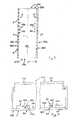
Figure 1 is a schematic view of an electrical household appliance for cooling and storing food according to this invention; -
Figure 2 is a front view of a door according to the invention where some parts not in view are shown with dashed lines; -
Figure 3 shows a partly interrupted view of a cross section through the plane A-A ofFigure 2 . - With reference to the accompanying drawings, the numeral 1 denotes an electrical household appliance for cooling and storing food.
- The electrical household appliance 1 comprises: a cooled compartment 2 for receiving the food to be stored and a
door 3 giving access to the compartment 2. - For example, the electrical household cooling appliance 1 may be a freezer or a refrigerator with freezer compartment (as shown in
Figure 1 , for example) or a refrigerator-freezer combination structure (in that case, there may be a single door giving access to both the cooling compartment and the freezer compartment or there may be two or more separate doors). - The
door 3 in turn comprises: - a
first face 31 directed towards the outside of the electrical household appliance 1, asecond face 32 at least partly directed towards the cooled compartment 2 (at least when thedoor 3 is closed; when thedoor 3 is closed, thesecond face 32 contributes to delimiting the cooled compartment 2; the first face and thesecond face - structural reinforcement means 4 interposed between the first and the
second face first insert 41. - The
door 3 extends in thickness between the first face and thesecond face - If there are two cooled compartments delimited by a
single door 3, thesecond face 32 is partly directed towards one of the two cooled compartments and partly directed towards the other of the two cooled compartments (when thedoor 3 is closed). In an alternative embodiment where thedoor 3 delimits a single cooled compartment 2, thesecond face 32 is directed towards the cooled compartment 2. - The
second face 32 forms part of the component sometimes referred to as "inner door panel" in the jargon of the trade. In the preferred embodiment, the perimeter of thefirst face 31 and/of thesecond face 32 is approximately rectangular. - The
first insert 41 comprises afirst layer 411 of material. Conveniently, thefirst layer 411 of material comprises an epoxy resin. - The
first insert 41 is applied to asupport 7 which is at least partly interposed between the first and thesecond face support 7 is conveniently metallic. Thefirst face 31 is integrated in thesupport 7. Thefirst insert 41 comprises asecond layer 413 comprising a composite material (more specifically, it comprises fibreglass). Thesecond layer 413 is adjacent to thefirst layer 411, thefirst layer 411 being interposed between thesupport 7 and thesecond layer 413. - Conveniently, the
first insert 41 is made with a product available under the trade name "Nitohard" by Nitto Denko. More specifically, thefirst insert 41 is made with a product available under the trade name "Nitohard RE-1000" by Nitto Denko. An example of thefirst insert 41 is disclosed in patent documentEP1531040 . - The
first layer 411 comprises anadhesive surface 412 by which thefirst layer 411 is glued to thesupport 7. - The
adhesive surface 412 covers the surface of thefirst layer 411 opposite the one that interfaces with thesecond layer 413. - Advantageously, the
door 3 comprises apanel 310 which thefirst face 31 forms part of, and acoating 320 which thesecond face 32 forms part of. Advantageously, thefirst insert 41 and thefirst layer 411 are interposed between thepanel 310 and thecoating 320. Advantageously, thepanel 310 is made of a metallic material. Thepanel 310 advantageously coincides with thesupport 7. Thefirst face 31 is thus integrated in thesupport 7 and thefirst insert 41 is applied to asurface 311 of thesupport 7 opposite thefirst face 31. Thecoating 320 coincides with the inner door panel of thedoor 3. Thecoating 320 is normally made of a plastic material. - The invention makes it possible to decrease the weight of the
first insert 41 considerably compared to a known solution where there is a metallic upright inside the door. The weight of thedoor 3 is thus reduced without penalizing the structural stiffness features needed to resist the deformation of thedoor 3 caused by the cyclical thermal gradient existing between the inside and the outside of the compartment 2. Before the electrical household appliance 1 is finished, thefirst layer 411 undergoes a heat treatment which causes it to expand and acquire its final structural resistance properties. - The
door 3 comprises anedge 33 which is interposed between the first face and thesecond face - The four sides of the closed, rectangular line of extension comprise a first and a
third side fourth side - The first and the
third side fourth side - The
edge 33 comprises a first, a second, a third and afourth part fourth side edge 33. Considered individually, the first, second, third andfourth parts fourth parts edge 33, if observed from the first face towards thesecond face - The
first insert 41 extends along a principal direction ofextension 410. - The
first layer 411 extends for a length which is greater than or equal to one half, preferably three quarters, of the length of the first orthird side first layer 411 extends for a length which is approximately equal to the length of the first and/orthird side - The extensions of the
first insert 41 along the principal direction ofextension 410 of thefirst insert 41 cross the second and thefourth part edge 33. - This orientation of the principal direction of
extension 410 of thefirst insert 41 makes it possible to optimize the structural resistance of thedoor 3 to deformation caused by the thermal gradient between the inside and outside of the compartment 2. In effect, deformation mostly affects a segment that extends between a point on the second side and a point on thefourth side 332, 334 (that is to say, it occurs along the principal direction of extension of the door 3). That is the case whether thedoor 3 extends mainly vertically (as for example in the embodiment ofFigure 1 ) or mainly horizontally (in the latter case — an embodiment which is not illustrated — under thedoor 3 there is usually a chest in which the food to be kept in cold storage is placed). The embodiment withvertical door 3 applies to refrigerators, freezers or combined refrigerator-freezers, whilst the embodiment with horizontal door applies almost exclusively to freezers. - Let us define an
imaginary reference plane 5 interposed between the first and thethird side third side - More specifically, the
imaginary plane 5 is interposed between the first and thethird part 335, 337 of theedge 33 of thedoor 3 and is equidistant from them. Preferably, theimaginary plane 5 is substantially a plane of symmetry of theedge 33 of thedoor 3. Advantageously, theimaginary plane 5 is at right angles to the first face 31 (if the latter extends substantially in a single plane). The electrical household appliance 1 comprises at least onehinge 6 for connecting thedoor 3 to the rest of the electrical household appliance 1. Thehinge 6 is applied at the first part 335 of theedge 33. - This is the case, especially but not exclusively, of electrical household cooling and storage appliances 1 with
vertical door 3. - The
first insert 41 is entirely interposed between theimaginary plane 5 and thethird part 337 of theedge 33. The part of thedoor 33 along the long side of theedge 33 of thedoor 3 and furthest from thehinge 6 is usually the part most subject to deformation caused by the thermal gradient between the inside and outside of the cooled compartment 2. Thus, the presence of one ormore hinges 6 might contribute to connecting the first part 335 of theedge 33 of thedoor 3 while limiting the latter's deformation. - The structural reinforcement means 4 comprise a
second insert 42 comprising athird layer 421 of material. Conveniently, thethird layer 421 of material comprises an epoxy resin. - Conveniently, the
second insert 42 is made with a product available under the trade name "Nitohard" by Nitto Denko. More specifically, thesecond insert 42 is made with a product available under the trade name "Nitohard RE-1000" by Nitto Denko. Conveniently, thesecond insert 42 is applied to thesupport 7. Thesecond insert 42 comprises afourth layer 414 adjacent to thethird layer 421 and made of a composite material (for example, fibreglass). Thethird layer 421 is conveniently interposed between thefourth layer 414 and thesupport 7. - The
third layer 421 comprises anadhesive surface 415 by which thethird layer 421 is glued to thesupport 7. Thesecond insert 42 is applied to the surface of thesupport 7 opposite the first face 31 (the same surface thefirst insert 41 is applied to). Theadhesive surface 415 extends over the surface of thethird layer 421 opposite the one that interfaces with thefourth layer 414. - Conveniently, the
second insert 42 and thethird layer 421 are interposed between thepanel 310 and thecoating 320. - The
second insert 42 extends along a principal direction ofextension 420. - In the expressions "third layer" and "fourth layer" the adjectives "third" and "fourth" are used to distinguish them from the "first layer" and the "second layer" relating to the
first insert 41. The adjectives "third" and "fourth" do not imply that that thesecond insert 42 also has a first and a second layer (not further specified) applied to it. Also, the materials thefirst insert 41 is made of advantageously coincide with those thesecond insert 42 is made of Preferably, the first and/or thesecond layer fourth layer - The
second insert 42 is entirely interposed between theimaginary plane 5 and the first part 335 of theedge 33. - The
second insert 42 extends for a length which is greater than or equal to at least one half, preferably three quarters, of the length of the first orthird side second insert 42 extends for a length which is approximately equal to the length of the first orthird side - The
first insert 41 is located close to thethird part 337 of theedge 33 and thesecond insert 42 is located close to the first part 335 of theedge 33. - The
first insert 41 may be regarded as an upright of thedoor 3. The same applies to thesecond insert 42. - The principal direction of extension of the
second insert 42 is parallel to the principal direction of extension of thefirst insert 41. - The
support 7 extends in thickness between thefirst face 31 and asecond face 32 inside thedoor 3. Advantageously, the first and/or thesecond insert surface 311 of thesupport 7 opposite thefirst face 31. - The
door 3 conveniently comprises thermal insulation means. The thermal insulation means comprise a solidified polyurethane foam interposed between the first and thesecond face second insert second face door 3. In that case, the VIP panels would be located between the first or thesecond insert second face 32. - This invention also has for an object a method for making the
door 3 of an electrical household appliance 1 having one or more of the technical features described above. The method comprises the steps of: - procuring the
panel 310; - connecting to the
panel 310 at least thefirst insert 41 comprising thefirst layer 411 of material comprising an epoxy resin, thefirst layer 411 of material being thermally expandable; - heating the
panel 310 and thefirst layer 411 to a temperature greater than or equal to a predetermined temperature and for a length of time greater than or equal to a predetermined length of time to allow thefirst layer 411 to expand and harden; - connecting to the
panel 310 thecoating 320 comprising thesecond face 32, thefirst insert 41 remaining interposed between thepanel 310 and thecoating 320. - Conveniently, the method comprises a step of applying a layer of powdered paint to a first surface of the
panel 310, thepanel 310 coinciding with thesupport 7 and the first surface being at least partly designed to form part of thefirst face 31 of thedoor 3; the step of applying a layer of powdered paint to the first surface of thepanel 310 is performed before the step of heating thepanel 310 and thefirst layer 411 so that, during the subsequent step of heating thepanel 310 and thefirst layer 411, the powdered paint can melt and expand simultaneously with the expansion and hardening of thefirst layer 411. - Advantageously, the predetermined temperature is 170°, preferably 180°. Conveniently, the predetermined length of time is 7 minutes, preferably equal to 10 minutes.
- The step of connecting the
coating 320 to thepanel 310 may be performed before or after the step of heating thepanel 310 and the first layer 411: preferably after. After connecting thecoating 320 to thepanel 310, an insulating material, in particular a polyurethane foam which allows better thermal insulation, is placed in the space between thepanel 310 and thecoating 320. - The step of rigidly connecting to the
panel 310 at least the firstmetallic insert 41 to which is applied thefirst layer 411 of material comprising an epoxy resin entails connecting the first insert to thepanel 310 by gluing. To perform the gluing step, a protective film is removed from theadhesive layer 412 of thefirst layer 411. A similar operation is performed on thesecond insert 42 if thesecond insert 42 needs to be connected to thepanel 310; in that case, a protective film is removed from theadhesive surface 415. - Lastly, the
door 3 is connected to the rest of the electrical household appliance 1 by at least onehinge 6. Preferably, the step of connecting thefirst insert 41 to thepanel 310 is accompanied by the step of connecting thesecond insert 42 to thepanel 310. Similarly, the step of heating thepanel 310 and thefirst layer 411 is simultaneous with the step of heating thethird layer 421. - This invention has important advantages. In particular, it allows a reduction of the weight of the means used for stiffening the door giving access to the cooled compartment but without affecting its structural resistance. That allows the construction of doors which, under equal conditions of structural resistance, are lighter in weight and thus easier for a user to move (this is particularly advantageous considering the fact that the door of a household refrigerator or freezer is normally opened and closed by anyone in the family, including children). The lighter weight also facilitates on-line assembly.
- It shall be understood that the invention described above may be modified and adapted in several ways without departing from the scope of the inventive concept. Moreover, all the details of the invention may be substituted by other technically equivalent elements. Further, the embodiments of the invention may be made in any size, depending on requirements.
Claims (12)
- An electrical household appliance for cooling and storing food comprising a cooled compartment (2) for receiving the food to be stored and a door (3) giving access to the compartment (2), the door (3) in turn comprising:- a first face (31) directed towards the outside of the electrical household appliance (1), a second face (32) at least partly directed towards the cooled compartment (2) when the door (3) is closed;- structural reinforcement means (4) interposed between the first and the second face (31, 32) and comprising at least one insert (41);characterized in that the first insert (41) comprises a first layer of material (411) comprising an epoxy resin, the first insert (41) being applied to a support (7) at least partly interposed between the first and the second face (31, 32).
- The electrical household appliance according to claim 1, characterized in that the support (7) is made of metal and the first layer (411) comprises an adhesive surface (412) by which the first insert (41) is glued to the support (7).
- The electrical household appliance according to claim 1 or 2, characterized in that the first face (31) is integrated in the support (7).
- The electrical household appliance according to any of the foregoing claims, characterized in that the door (3) comprises an edge (33) which is interposed between the first and the second face (31, 32) and which extends principally along a closed, rectangular line of extension, the four sides of the closed, rectangular line of extension comprising a first and a third side (331, 333), which are parallel with each other and not consecutive, and a second and a fourth side (332, 334) which are parallel with each other and not consecutive, the first and the third side (331, 333) being greater in length than the second and the fourth side (332, 334); the edge (33) comprising a first, a second, a third and a fourth part (335, 336, 337, 338) which extend, respectively, along the first, the second, the third and the fourth side (331, 332, 333, 334) of the line of extension of the edge (33).
- The electrical household appliance according to claim 4, characterized in that the first insert (41) extends along a principal direction of extension (410), the extensions of the first insert (41) along the principal direction of extension (410) of the first insert (41) crossing the second and the fourth part (336, 338) of the edge (33).
- The electrical household appliance according to claim 4 or 5, where an imaginary reference plane (5) is interposed between the first and the third side (331, 333) and is equidistant from the first and the third side (331, 333), characterized in that it comprises at least one hinge (6) for connecting the door (3) to the rest of the electrical household appliance (1), the hinge (6) being applied at the first part (335) of the edge (33); the first insert (41) being entirely interposed between the imaginary plane (5) and the third part (337) of the edge (33).
- The electrical household appliance according to any of the foregoing claims, characterized in that the structural reinforcement means (4) comprise a second insert (42) extending along a principal direction of extension (420) and comprising a second layer (413) of material which is applied to the support (7) and which comprises an epoxy resin.
- The electrical household appliance according to claim 7 when it depends directly or indirectly on claim 6, characterized in that the second metal insert (42) is entirely interposed between the imaginary plane (5) and the first part (335) of the edge (33).
- The electrical household appliance according to claim 8 or according to claim 7 when it depends directly or indirectly on claim 4, characterized in that the first insert (41) is located close to the third part (337) of the edge (33) and the second insert (42) is located close to the first part (335) of the edge (33).
- The electrical household appliance according to claim 7, 8 or 9, characterized in that the principal direction of extension of the second insert (42) is parallel to the principal direction of extension of the first insert (41).
- A method for making the door of the electrical household appliance according to any of the foregoing claims from 1 to 10, characterized in that it comprises the following steps:- procuring a panel (310);- gluing to the panel (310) at least the first insert (41) comprising the first layer (411) of material comprising an epoxy resin, the first layer (411) being thermally expandable;- heating the panel (310) and the first layer (411) to a temperature greater than or equal to a predetermined temperature and for a length of time greater than or equal to a predetermined length of time to allow the first layer (411) to expand and harden;- connecting to the panel (310) a coating (320) comprising the second face (32), the first insert (41) remaining interposed between the panel (310) and the coating (320).
- The method according to claim 11, characterized by:- applying a layer of powdered paint to a first surface of the panel (310), the panel (310) coinciding with the support (7) and the first surface being at least partly designed to form part of the first face (31) of the door (3); this step being performed before the step of heating the panel (310) and the first layer (411) so that, during the subsequent step of heating the panel (310) and the first layer (411), the powdered paint can melt and expand simultaneously with the expansion and hardening of the first layer (411).
Applications Claiming Priority (1)
| Application Number | Priority Date | Filing Date | Title |
|---|---|---|---|
| IT000009A ITRN20100009A1 (en) | 2010-03-23 | 2010-03-23 | FOOD REFRIGERATION APPLIANCES |
Publications (1)
| Publication Number | Publication Date |
|---|---|
| EP2369276A1 true EP2369276A1 (en) | 2011-09-28 |
Family
ID=42831664
Family Applications (1)
| Application Number | Title | Priority Date | Filing Date |
|---|---|---|---|
| EP11157602A Withdrawn EP2369276A1 (en) | 2010-03-23 | 2011-03-10 | Electrical household appliance for cooling food |
Country Status (2)
| Country | Link |
|---|---|
| EP (1) | EP2369276A1 (en) |
| IT (1) | ITRN20100009A1 (en) |
Citations (7)
| Publication number | Priority date | Publication date | Assignee | Title |
|---|---|---|---|---|
| GB508413A (en) * | 1937-04-24 | 1939-06-30 | Electrolux Ltd | Improvements in or relating to doors for refrigerator and other heat-insulated cabinets |
| US6190490B1 (en) * | 1998-12-16 | 2001-02-20 | Joseph R. Tippmann | Method of making a closure member for a refrigerated storage enclosure |
| US20040241413A1 (en) * | 2003-05-30 | 2004-12-02 | Felisa Blazek | Surface-covering article and methods of installing the same |
| US20040266899A1 (en) * | 2001-12-21 | 2004-12-30 | Xaver Muenz | Expandable epoxy resin-based systems modified with thermoplastic polymers |
| EP1531040A2 (en) | 2003-11-04 | 2005-05-18 | Nitto Denko Corporation | Method of reinforcing a steel plate with a resin rubber composition |
| US20050257495A1 (en) * | 2004-03-25 | 2005-11-24 | Lg Electronics Inc. | Door for refrigerator |
| JP2008132604A (en) * | 2006-11-27 | 2008-06-12 | Matsushita Electric Ind Co Ltd | Refrigerator door |
-
2010
- 2010-03-23 IT IT000009A patent/ITRN20100009A1/en unknown
-
2011
- 2011-03-10 EP EP11157602A patent/EP2369276A1/en not_active Withdrawn
Patent Citations (7)
| Publication number | Priority date | Publication date | Assignee | Title |
|---|---|---|---|---|
| GB508413A (en) * | 1937-04-24 | 1939-06-30 | Electrolux Ltd | Improvements in or relating to doors for refrigerator and other heat-insulated cabinets |
| US6190490B1 (en) * | 1998-12-16 | 2001-02-20 | Joseph R. Tippmann | Method of making a closure member for a refrigerated storage enclosure |
| US20040266899A1 (en) * | 2001-12-21 | 2004-12-30 | Xaver Muenz | Expandable epoxy resin-based systems modified with thermoplastic polymers |
| US20040241413A1 (en) * | 2003-05-30 | 2004-12-02 | Felisa Blazek | Surface-covering article and methods of installing the same |
| EP1531040A2 (en) | 2003-11-04 | 2005-05-18 | Nitto Denko Corporation | Method of reinforcing a steel plate with a resin rubber composition |
| US20050257495A1 (en) * | 2004-03-25 | 2005-11-24 | Lg Electronics Inc. | Door for refrigerator |
| JP2008132604A (en) * | 2006-11-27 | 2008-06-12 | Matsushita Electric Ind Co Ltd | Refrigerator door |
Also Published As
| Publication number | Publication date |
|---|---|
| ITRN20100009A1 (en) | 2011-09-24 |
Similar Documents
| Publication | Publication Date | Title |
|---|---|---|
| EP2660545B1 (en) | Refrigerator and method of manufacturing door thereof | |
| JP5998360B2 (en) | refrigerator | |
| CN103673453B (en) | Refrigeration appliance | |
| US20120279247A1 (en) | Fresh food compartment ice box door | |
| EP3394532A1 (en) | Adhesively secured vacuum insulated panels for refrigerators | |
| JP6078794B2 (en) | refrigerator | |
| JP6140349B2 (en) | Manufacturing method of refrigerator and refrigerator door | |
| CN106052276A (en) | Refrigerator | |
| WO2014038189A1 (en) | Refrigerator | |
| JP6244545B2 (en) | refrigerator | |
| CN104884883A (en) | Wall for a household refrigeration appliance with a top layer comprising high-gloss polystyrene and/or silver particles and household appliance comprising said type of wall | |
| CN221324842U (en) | Door body assembly and refrigeration equipment | |
| JP3823993B2 (en) | refrigerator | |
| CN205482040U (en) | refrigerator | |
| KR101273655B1 (en) | Kimchi refrigerator | |
| KR20140027442A (en) | Refrigerator and method of manufacturing door thereof | |
| JP6113610B2 (en) | refrigerator | |
| DE29804099U1 (en) | Vacuum insulation panels in refrigerators and freezers | |
| JP5633626B2 (en) | refrigerator | |
| CN222617333U (en) | Door for refrigeration equipment and refrigeration equipment | |
| JP5633627B2 (en) | refrigerator | |
| KR200349339Y1 (en) | Refrigerator and storage container formed as one body whereof | |
| CN103038586B (en) | Door leaf and refrigeration device with door leaf | |
| KR100813686B1 (en) | Home appliances door | |
| JP6262906B2 (en) | refrigerator |
Legal Events
| Date | Code | Title | Description |
|---|---|---|---|
| PUAI | Public reference made under article 153(3) epc to a published international application that has entered the european phase |
Free format text: ORIGINAL CODE: 0009012 |
|
| AK | Designated contracting states |
Kind code of ref document: A1 Designated state(s): AL AT BE BG CH CY CZ DE DK EE ES FI FR GB GR HR HU IE IS IT LI LT LU LV MC MK MT NL NO PL PT RO RS SE SI SK SM TR |
|
| AX | Request for extension of the european patent |
Extension state: BA ME |
|
| 17P | Request for examination filed |
Effective date: 20120322 |
|
| STAA | Information on the status of an ep patent application or granted ep patent |
Free format text: STATUS: THE APPLICATION HAS BEEN WITHDRAWN |
|
| RAP1 | Party data changed (applicant data changed or rights of an application transferred) |
Owner name: WHIRLPOOL EMEA S.P.A |
|
| 18W | Application withdrawn |
Effective date: 20170123 |