EP2369196A2 - Water pump for vehicle - Google Patents
Water pump for vehicle Download PDFInfo
- Publication number
- EP2369196A2 EP2369196A2 EP11155361A EP11155361A EP2369196A2 EP 2369196 A2 EP2369196 A2 EP 2369196A2 EP 11155361 A EP11155361 A EP 11155361A EP 11155361 A EP11155361 A EP 11155361A EP 2369196 A2 EP2369196 A2 EP 2369196A2
- Authority
- EP
- European Patent Office
- Prior art keywords
- water pump
- pulley
- power transmitting
- wrap spring
- armature
- Prior art date
- Legal status (The legal status is an assumption and is not a legal conclusion. Google has not performed a legal analysis and makes no representation as to the accuracy of the status listed.)
- Withdrawn
Links
Images



Classifications
-
- F—MECHANICAL ENGINEERING; LIGHTING; HEATING; WEAPONS; BLASTING
- F16—ENGINEERING ELEMENTS AND UNITS; GENERAL MEASURES FOR PRODUCING AND MAINTAINING EFFECTIVE FUNCTIONING OF MACHINES OR INSTALLATIONS; THERMAL INSULATION IN GENERAL
- F16D—COUPLINGS FOR TRANSMITTING ROTATION; CLUTCHES; BRAKES
- F16D27/00—Magnetically- or electrically- actuated clutches; Control or electric circuits therefor
- F16D27/10—Magnetically- or electrically- actuated clutches; Control or electric circuits therefor with an electromagnet not rotating with a clutching member, i.e. without collecting rings
- F16D27/105—Magnetically- or electrically- actuated clutches; Control or electric circuits therefor with an electromagnet not rotating with a clutching member, i.e. without collecting rings with a helical band or equivalent member co-operating with a cylindrical coupling surface
Definitions
- the rotation of the power transmitting member may be transmitted to the driven shaft via the biasing member contacting to the power transmitting member, and the rotation is eventually transmitted to the impeller.
- the length of the biasing member in the radial direction of the biasing member is not controlled, because the biasing member is pressed toward the inner circumferential surface of the power transmitting member by use of the biasing force of the biasing member itself, the inner circumferential surface of the power transmitting member and the biasing member come in contact with each other. Accordingly, even when the controlling member cannot control the length of the biasing member in the radial direction of the biasing member, the water pump for the vehicle may be driven.
- Fig. 7 is a detailed view indicating an actuation of a controlling member of the water pump of the second embodiment.
- a water pump 1 for a vehicle of a first embodiment will be explained with reference to Figs. 1 through 4 .
- the attracting force generated at the attraction face 6b by the electromagnetic coil 6 effectively acts on the armature 42.
- the attracting force is a magnetic force generated by the electromagnetic coil 6
- a level of efficiency of the magnetic force may be increased compared to a case where a component or the like is partially positioned between the armature 42 and the attraction face 6b of the electromagnetic coil 6.
- the attraction face 6b entirely faces the armature 42, and the air gap 13 is provided between the armature 42 and the attraction face 5b, the electromagnetic force generated at the electromagnetic coil 6 effectively acts on the entire armature 42.
- the armature 42 may smoothly move in the axial direction of the driven shaft 5
- the contacting state between the pulley 2 and the wrap spring 3 may be switched to the disengaging state with high accuracy, at the same time the contacting state between the pulley 2 and the wrap spring 3 may be controlled with high accuracy, accordingly the water pump having such configuration may be easily adapted to a vehicle with high reliability.
- the water pump 1 is driven or stopped in accordance with a warming stated of each of components of the vehicle, such as the internal-combustion engine. For example, in a case where a temperature of the engine is relatively low, the water pump 1 is stopped in order to stop the coolant circulation, thereby executing the heating of the engine. On the other hand, in a case where the temperature of the engine is relatively high, the water pump 1 is driven in order to circulate the coolant, thereby maintaining the temperature of the engine to reach an appropriate level. The appropriate level of the temperature of the engine is differently set to each type of vehicles.
- Figs. 7A and 7B are detailed views indicating an actuation of the controlling member 4 of the water pump 1a.
- Fig. 7A indicates a state of the controlling member 4 when the water pump 1a is driven.
- both of the driver 41 and the armature 42 are rotatable, and the wrap spring 3 biases itself so as to extend toward an inner circumferential surface 2a of the pulley 2, accordingly the wrap spring 3 contacts the inner circumferential surface 2a of the pulley 2.
Landscapes
- Engineering & Computer Science (AREA)
- General Engineering & Computer Science (AREA)
- Physics & Mathematics (AREA)
- Electromagnetism (AREA)
- Mechanical Engineering (AREA)
- Structures Of Non-Positive Displacement Pumps (AREA)
Abstract
Description
- This disclosure relates to a water pump for a vehicle having a mechanism for controlling rotation of an impeller.
- What is required for a water pump for a vehicle for circulating coolant to each component of a vehicle, for example to an internal-combustion engine, is to vary a supplying amount of the coolant as needed by applying a clutch mechanism to the water pump.
- For example, a known water pump disclosed in JP11-20119,IA includes a clutch mechanism configured by a wrap spring arranged about an input hub and an output shaft, a friction member connected to one of the input hub and the output shaft for rotating therewith, an armature connected to the wrap spring and an actuator for selectively causing the friction member and the armature to frictionally engage each other, where the clutch mechanism selectively causes the wrap spring to frictionally engage the input hub or the output shaft in accordance with the frictional engagement between the friction member and the armature.
- Further, another known water pump disclosed in JPHB-002423Y includes a clutch mechanism configured by a solenoid, a pulley, an inner coupling member, an outer coupling member, an armature plate and a friction plate. The solenoid is fixed on an outer circumferential surface of an end portion of a bearing housing by a bracket. The pulley is freely rotatably supported via a bearing at an outer circumferential surface of an end portion of a driving shaft of the water pump, the driving shaft being freely rotatably inserted into the bearing housing. The inner coupling member is freely rotatably supported via the bearing at the outer circumferential surface of the end portion of the driving shaft. The outer coupling member, arranged so as to face the inner coupling member via viscosity fluid, is fixed at the outer circumferential surface of the end portion of the driving shaft. The armature plate, made of a magnetic material and facing the solenoid via the pulley, is fixed at the outer coupling member. The friction plate is attached to a side surface of the armature plate at the side of the pulley.
- Because each of the abovementioned clutch mechanisms has a complicated structure and is large in size, in a case where such clutch mechanism is applied to the water pump, the size of the pump itself may be increased.
- According to the cultch mechanism disclosed in
JP11-201191A - Furthermore, according to the electromagnetic clutch disclosed in
JPH8-002423Y - A need thus exists to provide a water pump having a clutch mechanism whose size is relatively small for switching a state of the water pump between a driving state and a stopping state at a desired timing on the basis of a warming state of each components of a vehicle, such as an internal-combustion engine, and to provided a water pump having the clutch mechanism, which may save electric power and may reduce in size and costs,
- According to an aspect of this disclosure, the water pump for a vehicle includes a power transmitting member rotationally driven by an external force, a driven shaft driven to be rotatable independently from the power transmitting member, an impeller to which a rotation of the driven shaft is transmitted, a biasing member for pressing an inner circumferential surface of the power transmitting member so as to be contactable and for rotating in order to transmit a rotation of the power transmitting member to the driven shaft when the biasing member contacts the inner circumferential surface of the power transmitting member, the biasing member being formed so as to be wound in a circumferential direction of the power transmitting member and a control member for allowing the power transmitting member and the biasing member to come in contact with each other or to come out of contact from each other and for controlling a contacting state between the power transmitting member and the biasing member.
- In this configuration, because of the controlling member for allowing the inner circumferential surface of the power transmitting member and the biasing member to come in contact with each other or to come out of contact from each other and for controlling a contacting state between the inner circumferential surface of the power transmitting member and the biasing member, the water pump may be driven or stopped by means of the controlling member. Further, in a case where the power transmitting member and the biasing member come in contact with each other, and the length of the biasing member in the radial direction thereof is not controlled, by virtue of the pressing force made by a total force of the biasing force of the biasing member and a centrifugal force acting on the biasing member, the engagement between the biasing member and the power transmitting member may be strong. Thus, without using a large clutch mechanism used in the known water pump, according to the water pump disclosed here, sufficiently large torque may be transmitted to the impeller. Furthermore, in a case where the power transmitting member and the biasing member in contact with each other, and the length of the biasing member in the radial direction thereof is controlled, the biasing member may slidingly contact the power transmitting member. Accordingly, the biasing member may transmit a rotational force being smaller than a rotation force of the power transmitting member to the impeller, thereby controlling an amount of a fluid outputted from the water pump,
- The clutch mechanism mentioned here indicates the power transmitting member and the biasing member. When the power transmitting member and the biasing member come in contact with each other, the clutch mechanism is actuated, and when the power transmitting member and the biasing member come out of contact from each other, the clutch mechanism is not actuated.
- According to another aspect of this disclosure, the control member has a driver connected to a first end portion of the biasing member and the driven shaft, a magnetically-attracted portion to which a second end portion of the biasing member is connected and a driving portion for attracting the magnetically-attracted portion by use of a magnetic force, wherein the driving portion controls a length of the biasing member in a radial direction of the biasing member by attracting the magnetically-attracted portion.
- In this configuration, by controlling the attracting force generated by the driving portion and acted on the magnetically-attracted portion, the length of the biasing member in the radial direction thereof may be controlled at an any desired timing in order to allow the power transmitting member and the biasing member to come in contact with each other or to come out of contact from each other and to control the contacting state between the power transmitting member and the biasing member. Further, because the driving portion controls the length of the biasing member in the radial direction thereof by applying a magnetic force to the magnetically-attracted portion, the water pump may not be structured in a complicated manner so as to be driven or stopped. Specifically, according to the water pump disclosed here, no additional structure may not be provided in order to control the length of the biasing member in the radial direction thereof, thereby simply actuating the magnetic force on the magnetically-attracted portion. Furthermore, the driving portion may control the length of the biasing member in the radial direction thereof by turning on or off the generation of the magnetic force, a level of responsibility of the water pump may be improved.
- According to a further aspect of this disclosure, the driving portion is provided so as to face the magnetically-attracted portion, and the driving portion includes an acting surface at which an attracting force acting on the magnetically-attracted portion is generated in order to attract the magnetically-attracted portion in an axial direction of the driven shaft.
- In this configuration, because the acting surface of the driving portion is provided so as to face the magnetically-attracted portion, the attracting force may be effectively acted to the magnetically-attracted portion. Thus, because the attracting force generated by the driving portion may be effectively acted on the magnetically-attracted portion, the driving portion may be downsized and may use much less power.
- According to a yet further aspect of this disclosure, the biasing member contacts the power transmitting member when the driving portion is in a stopping state.
- In this configuration, even when the driving portion cannot be actuated, the rotation of the power transmitting member may be transmitted to the driven shaft via the biasing member contacting to the power transmitting member, and the rotation is eventually transmitted to the impeller. Thus, in a case where the length of the biasing member in the radial direction of the biasing member is not controlled, because the biasing member is pressed toward the inner circumferential surface of the power transmitting member by use of the biasing force of the biasing member itself, the inner circumferential surface of the power transmitting member and the biasing member come in contact with each other. Accordingly, even when the controlling member cannot control the length of the biasing member in the radial direction of the biasing member, the water pump for the vehicle may be driven.
- According to a further aspect of this disclosure, the driving portion includes an acting surface for applying an attraction force from the driving portion to the magnetically-attracted portion, an entire surface of the acting surface facing the magnetically-attracted portion.
- The foregoing and additional features and characteristics of this disclosure will become more apparent from the following detailed description considered with the reference to the accompanying drawings, wherein:
-
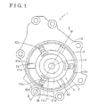
Fig. 1 is a detailed diagram indicating a configuration of each components of a water pump for a vehicle of the first embodiment; -
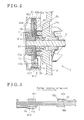
Fig. 2 is a cross sectional view of the water pump of the first embodiment, taken along 11-11 line inFig. 1 ; -
Fig. 3 is a side view of a controlling member of the water pump of the first embodiment; -
Fig. 4 is a detailed view indicating an actuation of the controlling member of the water pump of the first embodiment; -
Fig. 5 is a detailed diagram indicating a configuration of each of components of a water pump of the second embodiment; -
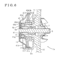
Fig. 6 is a cross sectional view of the water pump of the second embodiment, taken along Vl-Vl line inFig. 5 ; and -
Fig. 7 is a detailed view indicating an actuation of a controlling member of the water pump of the second embodiment. - A water pump 1 for a vehicle of a first embodiment will be explained with reference to
Figs. 1 through 4 . -
Fig, 1 is a diagram for indicating a configuration of the water pump 1 (hereinafter simply referred to as a water pump 1) of the first embodiment. As a matter of practical convenience, a pulley 2 (e,g., a power transmitting member) is partially shown inFig. 1 , specifically a cylindrical wall portion of thepulley 2 is only illustrated inFig. 1 . The water pump 1 is configured by apump housing 10, thepulley 2, a drivenshaft 5, a wrap spring 3 (e.g., a biasing member), a controllingmember 4 and a first bearing 11. Thepump housing 10 includes an inlet and an outlet through which a coolant flows, and thepulley 2 is driven so as to rotate by a driving force generated at an internal-combustion engine. The drivenshaft 5 is provided independently from thepulley 2 so as to be rotatably independently from thepulley 2. Thewrap spring 3 is formed so as to be wound in a circumferential direction of thepulley 2 in order to press an innercircumferential surface 2a of thepulley 2. so that thewrap spring 3 is contactable to the innercircumferential surface 2a of thepulley 2, thereby transmitting the rotation of thepulley 2 to the drivenshaft 5. The controllingmember 4 includes a driver 41 (illustrated inFig. 2 ) and an armature 42 (e.g., a magnetically-attracted portion) (illustrated inFig. 2 ), each of which is used for controlling thewrap spring 3 so that thewrap spring 3 and the innercircumferential surface 2a of thepulley 2 come in contact with each other or come out of contact from each other and is used for controlling a contacting state (a degree of the contact, for example a half-dutch state) between thepulley 2 and thewrap spring 3. The first bearing 11 is provided at an outer circumferential surface of a protrudingportion 4 1 a of thedriver 41. -
Fig, 2 is a cross sectional view of the water pump 1 of the first embodiment, taken along 11-11 line inFig .2 , The water pump 1 further includes an electromagnetic coil 6 (e,g., a driving portion), thedriver 41, thearmature 42, aplate spring 43, acore 6a, the first bearing 11. a second bearing 12 and an impeller 7. Theelectromagnetic coil 6 controls the contacting state between the innercircumferential surface 2a of thepulley 2 and thewrap spring 3 so as to be in an engaging state or a disengaging state. In other words, theelectromagnetic coil 6 controls thewrap spring 3 so that thewrap spring 3 and the innercircumferential surface 2a of thepulley 2 come in contact with each other or come out of contact from each other. Thedriver 41 is provided at one end of the drivenshaft 5, and afirst end portion 3a of the wrap spring 3 (indicated inFig. 1 ) is connected to thedriver 41 so that the rotation of thepulley 2 is transmitted to the drivenshaft 5. Thearmature 42 is provided so as to face theelectromagnetic coil 6, and when theelectromagnetic coil 6 is energized, thearmature 42 is attracted toward the drivenshaft 5 by theelectromagnetic coil 6 and fixed thereat. Asecond end portion 3b of thewrap spring 3 is connected to thearmature 42. Theplate spring 43 is provided between thedriver 41 and thearmature 42 in order to bias thearmature 42 so as to be detached from theelectromagnetic coil 6. Thecore 6a includes anattraction face 6b (e.g., an acting surface) functioning so as to fix theelectromagnetic coil 6 within thepump housing 10 in order to attract and fix thearmature 42 thereto. Thefirst bearing 11 is provided between thepulley 2 and the protrudingportion 41a of thedriver 41. Thesecond bearing 12 is provided between the drivenshaft 5 and thepump housing 10. The impeller 7 is provided at the second end of the drivenshaft 5. - The
driver 41 includes a plurality of first projectingportions 41b, a plurality ofwall portions 41c, a connectingportion 41d (Fig. 1 ) and a recessedportion 41e. The first projectingportions 41 b are formed so as to extend toward the innercircumferential surface 2a of thepulley 2. Each of the first projectingportions 41 b is formed with thewall portion 41c at which a radially variable range of thewrap spring 3 is regulated, The radially variable range is a range within which thewrap spring 3 varies from the contacting state to the disengaging state relative to thepulley 2. The connectingportion 41 d (Fig. 1 ), provided at one of the first projectingportions 41 b, is connected to thefirst end portion 3a of thewrap spring 3. Theplate spring 43 is provided at the recessedportion 41e of thedriver 41 so as to be inserted therein. Thewall portion 41c of thedriver 41 is shaped in such a way that each ofend portions 41f of thewall portions 41 c extends toward the innercircumferential surface 2a of thepulley 2, and thewarp spring 3 is provided within a space defined by theend portions 41f, thewall portion 41 c and the first projectingportion 41 b, so that an extension of thewrap spring 3 in the axial direction of the drivenshaft 5 is regulated. - The
armature 42 includes a plurality of second projectingportions 42a, a plurality ofwall portions 42b each of which is formed at each of the second projectingportions 42a, a connectingportion 42c (Fig. 1 ), a plurality of protrudingportions 42d each of which is formed on each of the second projectingportions 42a. Each of the second projectingportions 42a is formed so as to extend toward the innercircumferential surface 2a of thepulley 2, each of thewall portions 42b functions so as to regulate the radially variable range of thewrap spring 3. The connectingportion 42c, formed at one of thewall portions 42b of the second projecting portions 42a. is connected to thesecond end portion 3b of thewrap spring 3. The protrudingportion 42d is formed at each of the second projectingportions 42a and is connected to theplate spring 43. - The
plate spring 43 includes a plurality of third projectingportions 43a formed so as to extend toward the innercircumferential surface 2a of thepulley 2. Each of the third projectingportions 43a is connected to the each of the protrudingportions 42d of thearmature 42. Because theplate spring 43 biases thearmature 42 so as to be detached from theelectromagnetic coil 6, anair gap 13 is formed between thearmature 42 and theattraction face 6b of theelectromagnetic coil 6, Theair gap 13 is configured by layers of air. - Because the
air gap 13 is provided between thearmature 42 and anentire attraction face 6b, the attracting force generated at theattraction face 6b by theelectromagnetic coil 6 effectively acts on thearmature 42. ln other words, because the attracting force is a magnetic force generated by theelectromagnetic coil 6, a level of efficiency of the magnetic force may be increased compared to a case where a component or the like is partially positioned between thearmature 42 and theattraction face 6b of theelectromagnetic coil 6. Further, because theattraction face 6b entirely faces thearmature 42, and theair gap 13 is provided between thearmature 42 and the attraction face 5b, the electromagnetic force generated at theelectromagnetic coil 6 effectively acts on theentire armature 42. Because of the electromagnetic force acting on theentire armature 42, thearmature 42 may be moved in an axial direction of the drivenshaft 5 in a manner where thearmature 42 postures orthogonally to the axial direction of the drivenshaft 5. For example, in a case where the electromagnetic force intensively acts on one end portion of thearmature 42, in which thearmature 42 may move in the axial direction of the drivenshaft 5 in a manner where thearmature 42 inclines relative to the axial direction of the drivenshaft 5. ln this state, a level of responsiveness to control the rotational state of thearmature 42 may be decreased compared to the first embodiment, where the electromagnetic force of theelectromagnetic coil 6 acts on theentire armature 42. According to the first embodiment, because thearmature 42 may smoothly move in the axial direction of the drivenshaft 5, the contacting state between thepulley 2 and thewrap spring 3 may be switched to the disengaging state with high accuracy, at the same time the contacting state between thepulley 2 and thewrap spring 3 may be controlled with high accuracy, accordingly the water pump having such configuration may be easily adapted to a vehicle with high reliability. -
Fig. 3 is a side view of the controllingmember 4 of the water pump 1 of the first embodiment. Thewrap spring 3 is formed so as to round along the innercircumferential surface 2a of thepulley 2 in a rotational direction (e.g., a circumferential direction) of thepulley 2. Thewrap spring 3 is connected to the connectingportion 41 d of thedriver 41 and the connectingportion 42c of thearmature 42. The connectingportion 41d of thedriver 41 is formed at thewall portion 41 c of thedriver 41 at the side of the impeller 7 in the axial direction of the drivenshaft 5 as illustrated inFig. 3 , so that a length in a radial direction of thewrap spring 3 may be easily changed when the rotational state of thedriver 41 is changed to a non-rotating state. The connectingportion 42c of thearmature 42 is formed at thewall portion 42b of thearmature 42 at the side of thefirst bearing 11 in the axial direction of the drivenshaft 5 as illustrated inFig. 3 . The connectingportion 42c is formed so as to include a recessedportion 42e at one end of thewall portion 42b through which thesecond end portion 3b of thewrap spring 3 is inserted. Accordingly, the length in the radial direction of thewrap spring 3 may be easily changed when the rotational state of thearmature 42 is changed to the non-rotating state. While thefirst end portion 3a of thewrap spring 3 is connected to the connectingportion 41d of thedriver 41, and thesecond end portion 3b of thewrap spring 3 is connected to the connectingportion 42c of thearmature 42, thewrap spring 3 is formed so as to be wound in a spiral manner. -
Figs. 4A and 4B are detailed views indicating an actuation of the controllingmember 4 of the water pump 1. -
Fig. 4A indicates a state of the controllingmember 4 when the water pump 1 is driven, When the water pump 1 is driven, thedriver 41 and thearmature 42 are rotatable, and thewrap spring 3 biases itself toward the innercircumferential surface 2a of thepulley 2, accordingly the innercircumferential surface 2a of the pulley contacts thewrap spring 3. When the innercircumferential surface 2a of thepulley 2 contacts thewrap spring 3, theelectromagnetic coil 6 may control the rotational state of thearmature 42 by attracting thearmature 42, thereby controlling the rotational state of thedriver 41. By controlling the rotational state of thedriver 41, the pressing force of thewrap spring 3 applied to the innercircumferential surface 2a of thepulley 2 is controlled, accordingly the contacting state between the innercircumferential surface 2a of thepulley 2 and thewrap spring 3 is controlled. -
Fig. 4B indicates a state of the controllingmember 4 when the water pump 1 is stopped. When the water pump 1 is stopped, theelectromagnetic coil 6 attracts and fixes thearmature 42. Because thearmature 42 connected to theplate spring 43 is fixed by theelectromagnetic coil 6, thedriver 41, thearmature 42 and theplate spring 43 are frictionally contacting with each other. Because of the friction force between thearmature 42 and theplate spring 43, thedriver 41 is fixed in such a way that the innercircumferential surface 2a is detached from thewrap spring 3. At this point, thedriver 41 is fixed in a state where the connectingportion 41d is rotated toward the connectingportion 42c from the position indicated inFig. 4A . Accordingly, thedriver 41 and thearmature 42 are fixed in such a way that the length in the radial direction of thewrap spring 3 is shrunk from P1 to P2 inFigs. 4A and 4B . - The actuation of the water pump 1 of the first embodiment will be explained. The
pulley 2, thedriver 41 and thearmature 42 are rotatable in a counterclockwise direction inFigs. 4A and 4B . - The water pump 1 is driven or stopped in accordance with a warming stated of each of components of the vehicle, such as the internal-combustion engine. For example, in a case where a temperature of the engine is relatively low, the water pump 1 is stopped in order to stop the coolant circulation, thereby executing the heating of the engine. On the other hand, in a case where the temperature of the engine is relatively high, the water pump 1 is driven in order to circulate the coolant, thereby maintaining the temperature of the engine to reach an appropriate level. The appropriate level of the temperature of the engine is differently set to each type of vehicles.
- When the water pump 1 is driven (an initial state), the
electromagnetic coil 6 is in a stopping state (non-energized state), and as indicated inFig. 4A , thedriver 41 and thearmature 42 are rotatable, and thewrap spring 3 biases itself so as to extend toward the innercircumferential surface 2a of thepulley 2. In this state, the innercircumferential surface 2a of thepulley 2 contacts thewrap spring 3, and the rotation of thepulley 2 is transmitted to thedriver 41. The rotation of thedriver 41 is transmitted to the impeller 7 via the drivenshaft 5. When thepulley 2 contacts thewrap spring 3, and thepulley 2 rotates in synchronization with thewrap spring 3, by virtue of a pressing force made by a total force of the biasing force of thewrap spring 3 and a centrifugal force acting on thewrap spring 3, the engagement between thepulley 2 and thewrap spring 3 may be strong. Further, in a case where the engagement between thepulley 2 and thewrap spring 3 is tin the half-dutch state, although thewrap spring 3 rotates slidingly relative to thepulley 2, the rotation of thepulley 2 may be transmitted to thewrap spring 3, accordingly a rotational force whose level is smaller than the rotation of thepulley 2 is transmitted to the impeller 7. - In order to turn the water pump 1 being in the driving state to the stopping state, the
electromagnetic coil 6 is turned to an actuating state (an energized state) so as to attract thearmature 42 by a magnetic force, so that thearmature 42 is in contact to and fixed by theattraction face 6b of theelectromagnetic coil 6, After thearmature 42 is fixed, because thedriver 41 and thewrap spring 3 keep rotating in accordance with an inertia force, as indicated inFig. 4B , the first projectingportion 41 b of thedriver 41 being in the state indicated inFig. 4A is rotated toward the second projectingportion 42a of thearmature 42. Then, in a state where thesecond end portion 3b of thewrap spring 3 is fixed, because thewrap spring 3 is rotated in such a way that thefirst end portion 3a of thewrap spring 3 comes closer to thesecond end portion 3b, a wounding angle of thewrap spring 3 is increased. As indicated inFigs. 4A and 4B , thewrap spring 3 is detached from the innercircumferential surface 2a of thepulley 2 toward the rotating shaft of thepulley 2 by a distance that is equal to a difference between P1 and P2 inFig. 4A and 4B , accordingly the rotation of thepulley 2 is not transmitted to the impeller 7, thereby stopping the water pump 1. - When the water pump 1 being in the stopping state turns to the driving state, the
electromagnetic coil 6 is stopped (non-energized), and thearmature 42 is detached from theattraction face 6b of theelectromagnetic coil 6 by the biasing force of theplate spring 43, and thearmature 42 turns to be rotatable. Then, thewrap spring 3, connected to the connectingportion 41d of thedriver 41 and the connectingportion 42c of thearmature 42, biases itself toward the innercircumferential surface 2a of thepulley 2. and the first projectingportion 41 b of thedriver 41 is returned to the position indicated inFig. 4A . Thus, because thedriver 41 becomes rotatable, the biasing force of thewrap spring 3 actuates itself, and the length in the radial direction of the wrap spring is increased compared to the case where the water pump 1 is in the stopping state, and then thewrap spring 3 eventually contacts the innercircumferential surface 2a of the pulley. 2, and the water pump 1 is actuated so as to be in the driving state, - According to the first embodiment, the controlling
member 4 may switch at an appropriate timing the contacting state between thewrap spring 3 and the innercircumferential surface 2a of thepulley 2 to the engaging state or the disengaging state, accordingly the water pump may be switched to be the driving state or the stopping state. For example, the temperature of the engine serving as an internal-combustion engine is relatively low, the water pump 1 is turned to the stopping state, thereby executing the heating of the engine. In this configuration, cooling loss of the engine and friction loss of a piston and/or a cylinder may be reduced, accordingly a level of fuel economy may be increased. Further, because the cooling loss of the engine may be reduced, the temperature of the engine may be rapidly increased, accordingly incomplete combustion of the fuel may be reduced, at the same time a level of emission gas may be decreased. - A water pump 1a of a second embodiment will be explained in accordance with
Figs. 5 through 4 . - A configuration, of the water pump 1a of the second embodiment is basically similar to the water pump 1 of the first embodiment, and the differences therebetween will be emphasized in the following explanation of the second embodiment. Specifically, in the second embodiment, a position of the
first bearing 11, a position of theelectromagnetic coil 6 and a shape of theplate spring 43 in the first embodiment are changed, and the same numerals are used for the identical components in the first and second embodiment, -
Fig.5 is a detailed view indicating components of the water pump 1a. The water pump 1a includes aplate spring 43b provided at a protrudingportion 41g of a driver 41 (Fig. 6 ) and a protrudingportion 42d of an armature 42 (Fig. 6 ). Theplate spring 43b is formed so as to includes a longitudinal throughhole 43c within which the protrudingportion 41g is movable. -
Fig. 6 is a cross section of the water pump 1 a taken along a VI-VI line inFig. 5 . The water pump 1a includes afirst bearing 11, provided between thepulley 2 and thepump housing 10, and anelectromagnetic coil 6 provided between thefirst bearing 11 and thearmature 42. -
Figs. 7A and 7B are detailed views indicating an actuation of the controllingmember 4 of the water pump 1a.Fig. 7A indicates a state of the controllingmember 4 when the water pump 1a is driven. When the water pump 1a is driven, both of thedriver 41 and thearmature 42 are rotatable, and thewrap spring 3 biases itself so as to extend toward an innercircumferential surface 2a of thepulley 2, accordingly thewrap spring 3 contacts the innercircumferential surface 2a of thepulley 2. - When the inner
circumferential surface 2a contacts thewrap spring 3, theelectromagnetic coil 6 attracts thearmature 42 in order to control the rotational state of thearmature 42, so that the rotational state of thedriver 41 is also controller, Because the rotational state of thedriver 41 is controlled, the pressing force of thewrap spring 3 applied to the innercircumferential surface 2a of thepulley 2 is controlled, thereby controlling the contacting state between the innercircumferential surface 2a and thewrap spring 3. -
Fig. 7B indicates a state of the controllingmember 4 when the water pump 1a is stopped. When the water pump 1a is stopped, theelectromagnetic coil 6 attracts and fixes thearmature 42. Because thearmature 42 connected to theplate spring 43b is fixed by theelectromagnetic coil 6, thedriver 41, thearmature 42 and theplate spring 43b are frictionally contacting with each other. By virtue of the frictional force between thearmature 42 and theplate spring 43b, thedriver 41 may be fixed in a manner where the innercircumferential surface 2a is detached from thewrap spring 3. At this point, thedriver 41 is fixed in a state where the connectingportion 41 d is rotated toward the connectingportion 42c from the position indicated inFig. 7A . Accordingly, thedriver 41 and thearmature 42 are fixed in such a way that the length in the radial direction of thewrap spring 3 is shrunk from P3 to P4 inFigs. 7A and 7B . - The actuation of the water pump 1a of the second embodiment will be explained. The
pulley 2, thedriver 41 and thearmature 42 are rotated in an anticlockwise direction inFigs. 7A and 7B . - When the water pump 1a is driven (an initial state), the
electromagnetic coil 6 is in a stopping state (non-energized state), and as indicated inFig. 7A , thedriver 41 and thearmature 42 are rotatable, and thewrap spring 3 biases itself so as to extend toward the innercircumferential surface 2a of thepulley 2. In this state, the innercircumferential surface 2a of thepulley 2 contacts thewrap spring 3, and the rotation of thepulley 2 is transmitted to thedriver 41. The rotation of thedriver 41 is transmitted to the impeller 7 via the drivenshaft 5. When thepulley 2 contacts thewrap spring 3, and thepulley 2 rotates in synchronization with thewrap spring 3, by virtue of a pressing force made by the biasing force of thewrap spring 3 and a centrifugal force acting at thewrap spring 3, the engagement between thepulley 2 and thewrap spring 3 may be strong. Further, in a case where the engagement between thepulley 2 and thewrap spring 3 is in the half-clutch state, although thewrap spring 3 rotates slidingly relative to thepulley 2, the rotation of thepulley 2 is transmitted to thewrap spring 3, accordingly a rotational force whose level is smaller than the rotation of thepulley 2 is transmitted to the impeller 7. - In order to turn the water pump 1a being in the driving state to the stopping state, the
electromagnetic coil 6 is turned to an actuating state (an energized state) so as to attract thearmature 42 by a magnetic force, so that thearmature 42 is contacted to and fixed by theattraction face 6b of theelectromagnetic coil 6. After thearmature 42 is fixed, because thedriver 41 and thewrap spring 3 keep rotating in accordance with an inertia force, as indicated inFig. 7B . the first projectingportion 41b of thedriver 41 being in the state indicated inFig. 7A is rotated toward the second projectingportion 42a of thearmature 42. Then, in a state where thesecond end portion 3b of thewrap spring 3 is fixed, because thefirst end portion 3a of thewrap spring 3 is rotated toward thesecond end portion 3b, a wounding angle of thewrap spring 3 is increased. Accordingly, as indicated inFigs. 7A and 7B , thewrap spring 3 is detached from the innercircumferential surface 2a of thepulley 2 toward the rotating shaft of thepulley 2 by a distance that is equal to a difference between P3 and P4 inFig. 7A and 7B , accordingly the rotation of thepulley 2 is not transmitted to the impeller 7, thereby stopping the water pump 1a. Other actuations are similar to the first embodiment. - According to the second embodiment, because the
first bearing 11 is positioned between thepulley 2 and thepump housing 10, a level of a load acting on the drivenshaft 5 may be decreased compared to that in the first embodiment. Specifically, in the first embodiment, thefirst bearing 11 its provided between thepulley 2 and the first end portion of the drivenshaft 5 being rotatably supported by thesecond bearing 12 as indicated inFig. 2 , while provided within thepump housing 10 in the second embodiment as indicated inFig. 6 . In other words, on one hand thepulley 2 of the first embodiment is rotatably supported by thepump housing 10, serving as a fixing member, via thesecond bearing 12, the drivenshaft 5 and thefirst bearing 11, on the other hand thepulley 2 of the second embodiment is rotatably supported by thepump housing 10, serving as a fixing member, via only thefirst bearing 11. Accordingly, on one hand a force received by thepulley 2 in the first embodiment (a pulling force of a belt toward a driving device such as the internal-combustion engine) intensively acts on the first end portion of the drivenshaft 5, on the other hand a force received by thepulley 2 in the second embodiment acts on thepump housing 10, serving as the fixing member, without passing through the drivenshaft 5. In this configuration, because the force received by thepulley 2 in the second embodiment does not intensively act on a certain portion of the drivenshaft 5, a level of frictional loss of the water pump 1 may be decreased, while decreasing frequency of a breakdown of the water pump 1, - According to the first and second embodiments, the
driver 41 is formed with the plurality of the first projectingportions 41b, and thearmature 42 its formed with the plurality of the second projectingportions 42a, however, the water pump of the first embodiment may be obtained in a configuration where at least one of the first projectingportions 41 b is provided and at least one of the second projectingportions 42a is provided. In the configuration where at least one of the first projectingportions 41 b is provided and at least one of the first projectingportions 42c is provided, the connectingportions portions 41f of each of thewait portions 41c of thedriver 41 is formed so as to extend toward the innercircumferential surface 2a of thepulley 2, however, thewall portions 41 c may be formed in the same manner as thewall portions 42b of thearmature 42, where end portions are not formed, In this configuration, the connectingportion 41d of thedriver 41 and the connectingportion 42c of thearmature 42 are located so as to be next to each other, however, the connectingportion 41d and the connectingportion 42c may not be next to each other. - A configuration where the
air gap 13 is formed may be replaced by a configuration where a pulling spring is provided between thedriver 41 and thearmature 42 in order to attract thearmature 42 toward thedriver 41. - A range in which the length of the
wrap spring 3 in the radial direction thereof can vary may be determined on the basis of a length of the first projectingportion 41 b of the driver, a thickness of thewall portion 41c, a level of the biasing force of thewrap spring 3 and a spring length of thewrap spring 3. A number of windings of the wrap sparing 3 may be changed on the basis of a thickness of thewrap spring 3, a distance between the connectingportion 41 d of thedriver 41 and the connectingportion 42c of thearmature 42 in an axial direction of the drivenshaft 5 and a position of theend portions 41 f of thedriver 41 in the axial direction of the drivenshaft 5. - According to the embodiment, a water pump for a vehicle includes a pulley rotationally driven by an external force, a driven shaft driven to be rotatable independently from the pulley, an impeller to which a rotation of the driven shaft is transmitted, a wrap spring for pressing an inner circumferential surface of the pulley so as to transmit a rotation of the pulley to the driven shaft, and a controlling member for controlling a pressing force of the wrap spring applied to the inner circumferential surface of the pulley, wherein the wrap spring is formed so as to be wound in a circumferential direction of the pulley, and the controlling member changes a length of the wrap spring in a radial direction of the wrap spring in order to allow the inner circumferential surface of the pulley and the wrap spring to come in contact with each other or to come out of contact from each other, and when the wrap spring contacts the inner circumferential surface of the pulley, the controlling member control the level of the pressing force of the wrap spring applied to the inner circumferential surface of the pulley.
- Thus, because the water pump for the vehicle includes the controlling member for allowing the pulley and the wrap spring to come in contact with each other or to come out of contact from each other, the water pump may be driven or stopped by use of the controlling member. Further, when the pulley and the wrap spring comes in contact with each other, the controlling member controls the pressing force applied from the wrap spring to the inner circumferential surface of the pulley, Accordingly, when the controlling member controls a level of the pressing force applied to the inner circumferential surface of the pulley so as to be relatively small, the wrap spring slidingly contacts the pulley. Thus, the wrap spring may transmit a rotational force that is smaller than a rotation force of the pulley to the impeller, thereby controlling an amount of a fluid outputted from the water pump. Further, when the controlling member controls the level of the pressing force applied to the inner circumferential surface of the pulley so as to be relatively large, by virtue of the pressing force made by the total force of the biasing force of the wrap spring and the centrifugal force acting on the wrap spring, the engagement between the wrap spring and the pulley may be strong. Thus, without using a large clutch mechanism used in the known waster pump, according to the water pump disclosed here, sufficiently large torque may be transmitted to the impeller.
- It is explicitly stated that all features disclosed in the description and/or the claims are intended to be disclosed separately and independently from each other for the purpose of original disclosure as well as for the purpose of restricting the claimed invention independent of the composition of the features in the embodiments and/or the claims. It is explicitly stated that all value ranges or indications of groups of entities disclose every possible intermediate value or intermediate entity for the purpose of original disclosure as well as for the purpose of restricting the claimed invention, in particular as limits of value ranges.
Claims (5)
- A water pump (1, 1a) for a vehicle, comprising:a power transmitting member (2) rotationally driven by an external force;a driven shaft (5) driven to be rotatable independently from the power transmitting member (2);an impeller (7) to which a rotation of the driven shaft (5) is transmitted:a biasing member (3) for pressing an inner circumferential surface (2a) of the power transmitting member (2) so as to be contactable and for rotating in order to transmit a rotation of the power transmitting member (2) to the driven shaft (5) when the biasing member (3) contacts the inner circumferential surface (2a) of the power transmitting member (2), the biasing member (3) being formed so as to be wound in a circumferential direction of the power transmitting member (2); anda control member (4) for allowing the power transmitting member (2) and the biasing member (3) to come In contact with each other or to come out of contact from each other and for controlling a contacting state between the power transmitting member (2) and the biasing member (3).
- The water pump (1, 1a) for the vehicle according to Claim 1, wherein the control member (4) includes a driver (41) connected to a first end portion (3a) of the biasing member (3) and the driven shaft (5), a magnetically-attracted portion (42) to which a second end portion (3b) of the biasing member (3) is connected and a driving portion (6) for attracting the magnetically-attracted portion (42) by use of a magnetic force, wherein the driving portion (6) controls a length of the biasing member (3) in a radial direction of the biasing member (3) by attracting the magnetically-attracted portion (42).
- The water pump (1, 1a) for the vehicle according to Claim 2, wherein the driving portion (6) is provided so as to face the magnetically-attracted portion (42), and the driving portion (6) includes an acting surface (6b) at which an attracting force acting on the magnetically-attracted portion (42) is generated in order to attract the magnetically-attracted portion (42) in an axial direction of the driven shaft (5).
- The water pump (1, 1a) for the vehicle according to any one of Claims 1 through 3, wherein the biasing member (3) contacts the power transmitting member (2) when the driving portion (6) is in a stopping state.
- The water pump (1, 1a) for the vehicle according to any one of Claims 2 through 4, wherein the driving portion (6) includes an acting surface (6b) for applying an attraction force from the driving portion (6) to the magnetically-attracted portion (42), an entire surface of the acting surface (6b) facing the magnetically-attracted portion (42).
Applications Claiming Priority (2)
| Application Number | Priority Date | Filing Date | Title |
|---|---|---|---|
| JP2010070949 | 2010-03-25 | ||
| JP2011029799A JP2011220326A (en) | 2010-03-25 | 2011-02-15 | Water pump for vehicle |
Publications (2)
| Publication Number | Publication Date |
|---|---|
| EP2369196A2 true EP2369196A2 (en) | 2011-09-28 |
| EP2369196A3 EP2369196A3 (en) | 2013-01-16 |
Family
ID=44202876
Family Applications (1)
| Application Number | Title | Priority Date | Filing Date |
|---|---|---|---|
| EP11155361A Withdrawn EP2369196A3 (en) | 2010-03-25 | 2011-02-22 | Water pump for vehicle |
Country Status (4)
| Country | Link |
|---|---|
| US (1) | US8545191B2 (en) |
| EP (1) | EP2369196A3 (en) |
| JP (1) | JP2011220326A (en) |
| CN (1) | CN102200049B (en) |
Families Citing this family (14)
| Publication number | Priority date | Publication date | Assignee | Title |
|---|---|---|---|---|
| ITTO20040824A1 (en) * | 2004-11-23 | 2005-02-23 | Dayco Europe Srl | DEVICE FOR OPERATING A RECIRCULATION PUMP FOR A COOLING CIRCUIT OF AN INTERNAL COMBUSTION ENGINE |
| JP5527611B2 (en) | 2010-11-04 | 2014-06-18 | アイシン精機株式会社 | Electromagnetic clutch |
| JP5257713B2 (en) * | 2011-02-10 | 2013-08-07 | アイシン精機株式会社 | Vehicle cooling system |
| JP5626595B2 (en) * | 2011-04-27 | 2014-11-19 | アイシン精機株式会社 | Electromagnetic clutch |
| CN103415721B (en) * | 2011-04-27 | 2016-07-06 | 爱信精机株式会社 | Electromagnetic clutch |
| JP5884417B2 (en) * | 2011-11-09 | 2016-03-15 | アイシン精機株式会社 | Electromagnetic clutch |
| EP2592296B1 (en) * | 2011-11-09 | 2014-01-15 | Aisin Seiki Kabushiki Kaisha | Electromagnetic clutch |
| JP5884416B2 (en) * | 2011-11-09 | 2016-03-15 | アイシン精機株式会社 | Electromagnetic clutch |
| US8942205B2 (en) * | 2012-01-24 | 2015-01-27 | Blackberry Limited | Performing idle mode mobility measurements in a mobile communication network |
| JP6096451B2 (en) * | 2012-09-21 | 2017-03-15 | 日立オートモティブシステムズ株式会社 | Water pump |
| JP5799058B2 (en) * | 2013-07-30 | 2015-10-21 | 三桜工業株式会社 | Negative pressure pump and cylinder head cover |
| CN103603886B (en) * | 2013-10-18 | 2016-03-30 | 龙口中宇机械有限公司 | Clutch |
| CN107327340B (en) * | 2016-04-28 | 2020-01-31 | 长城汽车股份有限公司 | Water pump and vehicle with same |
| CN114837792A (en) | 2021-03-10 | 2022-08-02 | 美普盛(上海)汽车零部件有限公司 | Electric coolant pump with expansion compensation sealing element |
Citations (2)
| Publication number | Priority date | Publication date | Assignee | Title |
|---|---|---|---|---|
| JPS60164022A (en) * | 1984-02-03 | 1985-08-27 | Matsushita Electric Ind Co Ltd | Solenoid spring clutch |
| JPH11201191A (en) | 1997-10-21 | 1999-07-27 | Dana Corp | Wrap spring clutch assembly |
Family Cites Families (17)
| Publication number | Priority date | Publication date | Assignee | Title |
|---|---|---|---|---|
| US3137236A (en) * | 1963-03-13 | 1964-06-16 | Twin Disc Clutch Co | Pressure control for fluid systems |
| GB1132714A (en) * | 1965-09-04 | 1968-11-06 | Wilmot Breeden Ltd | Improvements in or relating to clutches |
| JPS57107440A (en) | 1980-12-25 | 1982-07-03 | Honda Motor Co Ltd | Judder preventing device in centrifugal clutch |
| JPS57186627A (en) * | 1981-05-12 | 1982-11-17 | Matsushita Electric Ind Co Ltd | Spring clutch |
| JPH082423Y2 (en) * | 1989-07-31 | 1996-01-29 | 日本精工株式会社 | Driving force transmission device for water pump for automobile engine |
| JP2001200860A (en) | 1999-03-05 | 2001-07-27 | Nippon Soken Inc | Friction clutch |
| JP2001323949A (en) * | 2000-05-15 | 2001-11-22 | Toyota Industries Corp | Electromagnetic spring clutch |
| US7153227B2 (en) * | 2002-04-18 | 2006-12-26 | Litens Automotive | Isolator for alternator pulley |
| DE10232138A1 (en) * | 2002-07-12 | 2004-01-22 | Behr Gmbh & Co. | Device for driving a coolant pump |
| WO2005028901A1 (en) * | 2003-09-17 | 2005-03-31 | Plastech Engineering Gmbh | Auxiliary unit drive for a vehicle engine, comprising a couplable and uncouplable pulley, and auxiliary unit |
| JP5008928B2 (en) * | 2005-10-31 | 2012-08-22 | 三ツ星ベルト株式会社 | Pulley structure |
| JP2008038952A (en) * | 2006-08-02 | 2008-02-21 | Ntn Corp | Spring clutch |
| JP2008038992A (en) * | 2006-08-03 | 2008-02-21 | Ntn Corp | Spring clutch |
| DE102008016277A1 (en) * | 2008-03-28 | 2009-10-01 | Linnig Trucktec Gmbh | Electromagnetically actuated clutch and water pump with an electromagnetically actuated clutch |
| KR101657726B1 (en) | 2008-11-17 | 2016-09-19 | 리텐스 오토모티브 파트너쉽 | A helical coil clutch assembly comprising an actuator to effect engagement of helical coil clutch with a clutch surface |
| JP5526916B2 (en) | 2010-03-25 | 2014-06-18 | アイシン精機株式会社 | Vehicle water pump |
| JP5527611B2 (en) | 2010-11-04 | 2014-06-18 | アイシン精機株式会社 | Electromagnetic clutch |
-
2011
- 2011-02-15 JP JP2011029799A patent/JP2011220326A/en active Pending
- 2011-02-22 EP EP11155361A patent/EP2369196A3/en not_active Withdrawn
- 2011-03-08 US US13/042,922 patent/US8545191B2/en not_active Expired - Fee Related
- 2011-03-18 CN CN201110070383.6A patent/CN102200049B/en not_active Expired - Fee Related
Patent Citations (2)
| Publication number | Priority date | Publication date | Assignee | Title |
|---|---|---|---|---|
| JPS60164022A (en) * | 1984-02-03 | 1985-08-27 | Matsushita Electric Ind Co Ltd | Solenoid spring clutch |
| JPH11201191A (en) | 1997-10-21 | 1999-07-27 | Dana Corp | Wrap spring clutch assembly |
Also Published As
| Publication number | Publication date |
|---|---|
| JP2011220326A (en) | 2011-11-04 |
| EP2369196A3 (en) | 2013-01-16 |
| US8545191B2 (en) | 2013-10-01 |
| CN102200049A (en) | 2011-09-28 |
| US20110236230A1 (en) | 2011-09-29 |
| CN102200049B (en) | 2015-02-04 |
Similar Documents
| Publication | Publication Date | Title |
|---|---|---|
| EP2369196A2 (en) | Water pump for vehicle | |
| EP2369195B1 (en) | Water pump for vehicle | |
| KR100841272B1 (en) | Fluid Friction Clutch | |
| US8881881B2 (en) | Viscous clutch valve assembly | |
| CN101373007A (en) | Three-state overrunning clutch | |
| EP2669542B1 (en) | Electromagnetic clutch | |
| WO2012147509A1 (en) | Electromagnetic clutch | |
| US8061310B2 (en) | Valve timing control apparatus for internal combustion engine | |
| EP2705269A1 (en) | Pulley unit for bi-directional torque transfer | |
| JP5650838B2 (en) | Regulator for internal combustion engine valve drive | |
| US4151499A (en) | Rotary solenoid with indirectly coupled output shaft | |
| KR20120016122A (en) | Clutches or brakes in or on the transmission | |
| JP4295081B2 (en) | Valve timing control device for internal combustion engine | |
| JP2009091928A (en) | Valve timing control device for internal combustion engine | |
| JP5257716B2 (en) | Electromagnetic clutch | |
| WO2019183723A1 (en) | Energy efficient a/c compressor clutch | |
| WO2019014777A1 (en) | Rotary clutch assembly with actuator having threadingly engaged two-component armature | |
| JP4076398B2 (en) | Valve timing control device for internal combustion engine | |
| JP2008082343A (en) | Valve timing control device for internal combustion engine | |
| KR102359453B1 (en) | Clutch assembly for compressor of air conditioner of vehicle reducing power consumption | |
| JP2008082342A (en) | Valve timing control device for internal combustion engine | |
| JP2009228427A (en) | Valve timing control device of internal combustion engine | |
| JPH04121416A (en) | Refrigerant circulating pump of internal combustion engine | |
| JP2009203887A (en) | Valve timing controller for internal combustion engine | |
| JP2008215114A (en) | Valve timing control device for internal combustion engine |
Legal Events
| Date | Code | Title | Description |
|---|---|---|---|
| PUAI | Public reference made under article 153(3) epc to a published international application that has entered the european phase |
Free format text: ORIGINAL CODE: 0009012 |
|
| AK | Designated contracting states |
Kind code of ref document: A2 Designated state(s): AL AT BE BG CH CY CZ DE DK EE ES FI FR GB GR HR HU IE IS IT LI LT LU LV MC MK MT NL NO PL PT RO RS SE SI SK SM TR |
|
| AX | Request for extension of the european patent |
Extension state: BA ME |
|
| PUAL | Search report despatched |
Free format text: ORIGINAL CODE: 0009013 |
|
| AK | Designated contracting states |
Kind code of ref document: A3 Designated state(s): AL AT BE BG CH CY CZ DE DK EE ES FI FR GB GR HR HU IE IS IT LI LT LU LV MC MK MT NL NO PL PT RO RS SE SI SK SM TR |
|
| AX | Request for extension of the european patent |
Extension state: BA ME |
|
| RIC1 | Information provided on ipc code assigned before grant |
Ipc: F16D 27/105 20060101AFI20121212BHEP |
|
| 17P | Request for examination filed |
Effective date: 20130322 |
|
| 17Q | First examination report despatched |
Effective date: 20140811 |
|
| GRAP | Despatch of communication of intention to grant a patent |
Free format text: ORIGINAL CODE: EPIDOSNIGR1 |
|
| INTG | Intention to grant announced |
Effective date: 20160712 |
|
| STAA | Information on the status of an ep patent application or granted ep patent |
Free format text: STATUS: GRANT OF PATENT IS INTENDED |
|
| STAA | Information on the status of an ep patent application or granted ep patent |
Free format text: STATUS: THE APPLICATION IS DEEMED TO BE WITHDRAWN |
|
| 18D | Application deemed to be withdrawn |
Effective date: 20161123 |