EP2368717A2 - Printer - Google Patents
Printer Download PDFInfo
- Publication number
- EP2368717A2 EP2368717A2 EP20110159525 EP11159525A EP2368717A2 EP 2368717 A2 EP2368717 A2 EP 2368717A2 EP 20110159525 EP20110159525 EP 20110159525 EP 11159525 A EP11159525 A EP 11159525A EP 2368717 A2 EP2368717 A2 EP 2368717A2
- Authority
- EP
- European Patent Office
- Prior art keywords
- printhead
- transportation roller
- platen
- unit
- media transportation
- Prior art date
- Legal status (The legal status is an assumption and is not a legal conclusion. Google has not performed a legal analysis and makes no representation as to the accuracy of the status listed.)
- Granted
Links
Images


Classifications
-
- B—PERFORMING OPERATIONS; TRANSPORTING
- B41—PRINTING; LINING MACHINES; TYPEWRITERS; STAMPS
- B41J—TYPEWRITERS; SELECTIVE PRINTING MECHANISMS, i.e. MECHANISMS PRINTING OTHERWISE THAN FROM A FORME; CORRECTION OF TYPOGRAPHICAL ERRORS
- B41J3/00—Typewriters or selective printing or marking mechanisms characterised by the purpose for which they are constructed
- B41J3/60—Typewriters or selective printing or marking mechanisms characterised by the purpose for which they are constructed for printing on both faces of the printing material
-
- B—PERFORMING OPERATIONS; TRANSPORTING
- B41—PRINTING; LINING MACHINES; TYPEWRITERS; STAMPS
- B41J—TYPEWRITERS; SELECTIVE PRINTING MECHANISMS, i.e. MECHANISMS PRINTING OTHERWISE THAN FROM A FORME; CORRECTION OF TYPOGRAPHICAL ERRORS
- B41J11/00—Devices or arrangements of selective printing mechanisms, e.g. ink-jet printers or thermal printers, for supporting or handling copy material in sheet or web form
- B41J11/48—Apparatus for condensed record, tally strip, or like work using two or more papers, or sets of papers, e.g. devices for switching over from handling of copy material in sheet form to handling of copy material in continuous form and vice versa or point-of-sale printers comprising means for printing on continuous copy material, e.g. journal for tills, and on single sheets, e.g. cheques or receipts
-
- B—PERFORMING OPERATIONS; TRANSPORTING
- B41—PRINTING; LINING MACHINES; TYPEWRITERS; STAMPS
- B41J—TYPEWRITERS; SELECTIVE PRINTING MECHANISMS, i.e. MECHANISMS PRINTING OTHERWISE THAN FROM A FORME; CORRECTION OF TYPOGRAPHICAL ERRORS
- B41J2/00—Typewriters or selective printing mechanisms characterised by the printing or marking process for which they are designed
- B41J2/22—Typewriters or selective printing mechanisms characterised by the printing or marking process for which they are designed characterised by selective application of impact or pressure on a printing material or impression-transfer material
- B41J2/23—Typewriters or selective printing mechanisms characterised by the printing or marking process for which they are designed characterised by selective application of impact or pressure on a printing material or impression-transfer material using print wires
-
- B—PERFORMING OPERATIONS; TRANSPORTING
- B41—PRINTING; LINING MACHINES; TYPEWRITERS; STAMPS
- B41J—TYPEWRITERS; SELECTIVE PRINTING MECHANISMS, i.e. MECHANISMS PRINTING OTHERWISE THAN FROM A FORME; CORRECTION OF TYPOGRAPHICAL ERRORS
- B41J25/00—Actions or mechanisms not otherwise provided for
- B41J25/304—Bodily-movable mechanisms for print heads or carriages movable towards or from paper surface
- B41J25/308—Bodily-movable mechanisms for print heads or carriages movable towards or from paper surface with print gap adjustment mechanisms
Definitions
- the present invention relates to a printer that has plural printhead sets for printing on both sides of checks or other recording media, and relates more particularly to a printer having a mechanism that can suitably set the platen gap for each printhead assembly.
- Printers of this type are described as a media processing device in Japanese Unexamined Patent Appl. Pub. JP-A-2000-43339 , and as a hybrid processing device in Japanese Unexamined Patent Appl. Pub. JP-A-2010-20809 . These printers have a magnetic head for reading magnetic ink characters printed on checks, and two printhead assemblies for printing on the front and back sides of checks.
- the front printhead and back printhead that are used to respectively print on the front and back sides of checks or other recording media are mounted on frame members located on opposite sides of the recording medium transportation path.
- the platen that defines the printing position of the front printhead is mounted on a frame member on the same side as the back printhead, and the platen for the back printhead is similarly mounted on the frame member on the same side as the front printhead.
- the platen gap of both printheads is typically narrow at 0.5 mm or less, and precisely disposing the two printheads and platens mounted on different frame members so that such a precise, narrow gap can be achieved is not as simple as when there is only a single printhead and platen. More particularly, an external force that displaces both frame members can easily change both platen gaps, and adjusting the platen gaps is more difficult than when there is only one platen gap to be adjusted.
- a printer according to the present invention has a platen gap adjustment mechanism that can maintain a constant platen gap at plural locations.
- a first aspect of the invention is a printer having a first printhead unit on which a first printhead, a first media transportation roller, and a second platen are disposed; a second printhead unit that can move in a direction toward and away from the first media transportation roller, and on which a first platen is disposed at a position opposable to the first printhead, a second media transportation roller is disposed at a position where it can contact the first media transportation roller (in particular, the second media transportation roller may be movably disposed at a position such that it can come in contact with the first media transportation roller), and a second printhead is disposed at a position opposable to the second platen; and urging means, in particular an urging member or a combination of urging members, that urges the second printhead unit toward the first media transportation roller, and presses the second media transportation roller to the first media transportation roller.
- the relative positions of the two units are determined by the first and second media transportation rollers.
- the platen gaps of the first and second printheads are also held constant even when an external force displaces the units because contact between the first media transportation roller and second media transportation roller is held by the urging force of the urging member and the relative position of both units is held constant.
- the gap between the first media transportation roller and second media transportation roller changes according to the thickness of the recording medium conveyed therebetween.
- the relative positions of the first printhead unit and second printhead unit determined by contact between these rollers change.
- the gap between the first printhead on the first printhead unit side and the first platen on the second printhead unit side therefore changes as the thickness of the conveyed recording medium changes.
- the gap between the second printhead on the second printhead unit side and the second platen on the first printhead unit side changes similarly. Because the platen gaps change according to the thickness of the conveyed recording medium, the distance between the printhead units and the recording medium can be held to a constant size or greater.
- the second media transportation roller and second platen can be disposed to a member separate from the second printhead unit, and the first printhead unit and second printhead unit can be positioned by means of said member.
- a printer has a first printhead unit on which a first printhead, a first media transportation roller, and a second platen are disposed; a moving member that can move in a direction toward and away from the first media transportation roller, and on which a second media transportation roller is disposed at a position where it can come in contact with the first media transportation roller when the moving member moves towards the first media transportation roller, and a first platen is disposed at a position opposable to the first printhead; a first urging member that urges the moving member toward the first media transportation roller, and presses the second media transportation roller to the first media transportation roller; a second printhead unit that can move in a direction toward and away from the first media transportation roller, and on which a second printhead is disposed at a position opposable to the second platen; and a second urging member that urges the second printhead unit toward the first media transportation roller, and presses the second printhead unit to the moving member.
- the second media transportation roller disposed to the moving member is pressed by the first urging member to the first media transportation roller disposed to the first printhead unit.
- Contact between the first media transportation roller and second media transportation roller determines the position of the first printhead unit relative to the moving member, determines the position of the first printhead disposed to the first printhead unit relative to the first platen disposed to the moving member, and determines the platen gap of the first printhead.
- the second printhead unit is pressed by the second urging member to the moving member positioned to the first printhead unit, and the relative positions thereof are determined by contact between the moving member and the second printhead unit.
- the relative positions of the first printhead unit and second printhead unit, the position of the second printhead disposed to the second printhead unit relative to the second platen disposed to the first printhead unit, and the platen gap of the second printhead, are thus determined by means of the intervening moving member.
- the platen gap on the first printhead side is thus adjusted between the first printhead unit and the moving member, and the platen gap on the second printhead side is adjusted between the first printhead unit and second printhead unit.
- the platen gaps can therefore be adjusted more easily using three members than when the first printhead unit and second printhead unit are used to adjust the platen gaps therebetween.
- the other two when the first printhead unit, moving member, or second printhead unit is displaced by external force, for example, the other two also move and are displaced accordingly.
- the moving member follows the movement of the first printhead unit, and the second printhead unit moves according to the displacement of the moving member.
- the relative positions between the three components are therefore always held constant, and the platen gap determined by the first printhead and the first platen, and the platen gap determined by the second printhead and the second platen, are held constant.
- the first printhead unit and moving member are positioned relative to each other by contact between the first media transportation roller and second media transportation roller.
- the gap between these rollers changes according to the thickness of the conveyed recording medium.
- the position of the moving member relative to the first printhead unit that is determined by contact between these rollers changes, and the position of the second printhead unit determined by the moving member also changes.
- the gap between the first printhead on the first printhead unit side and the first platen on the moving member side therefore changes, and the gap between the second printhead on the second printhead unit side and the second platen on the first printhead unit side changes, according to the thickness of the conveyed recording medium. Because the platen gap thus increases according to the thickness of the conveyed recording medium, the distance between the printhead units and the recording medium can be held to a specific value or greater.
- a pivot member that can rotate on a predetermined pivot point can be used as the moving member, and a tension spring connected between the pivot member and the second printhead unit or a main frame of the printer can be used as the first urging member.
- one of the first printhead and second printhead when seen along the transportation direction of the recording medium passing the nip point of the first media transportation roller and second media transportation roller, one of the first printhead and second printhead is positioned on the upstream side in the transportation direction and the other is positioned on the downstream side in the transportation direction with the nip point therebetween. If the difference of the distance in the transportation direction from the nip point to the first printhead and the distance from the nip point to the second printhead differ greatly, the platen gap on the first printhead side and the platen gap on the second printhead side will differ greatly relative to the opening created between the first and second media transportation rollers by the thickness of the recording medium. The difference in the platen gaps to the recording medium thickness can be reduced by disposing the first and second printheads upstream and downstream from the nip point in the transportation direction.
- the first printhead and second printhead are dot impact heads, and the first printhead unit and second printhead unit each have an ink ribbon cassette loading unit. Because the second printhead unit can move and the gap between the first printhead and the first platen, and the gap between the second printhead and the second platen, increase when the second printhead unit is forcibly moved in the direction away from the first printhead unit side, the ink ribbon can be easily set in these gaps.
- a second media transportation roller disposed to a movable second printhead unit is pressed against a first media transportation roller on the first printhead unit side, thereby determin ing the relative positions therebetween.
- the platen gaps of the first printhead and second printhead can be held constant, and resistance to external disturbance of the platen gaps can be improved.
- the gap between the first and second media transportation rollers changes according to the thickness of the conveyed recording medium, and the platen gaps of the first and second printheads change, the platen gap increases according to the thickness of the conveyed recording medium, and the distance between the printhead units and recording medium can be held to a constant gap or greater.
- a check processing device (printer) according to a preferred embodiment of the present invention is described below with reference to the accompanying figures.
- FIG. 1 is an external oblique view of a check processing device.
- the check processing device 1 has a basically rectangular box-like outside case 2.
- a media insertion opening 3 for inserting a check (not shown in the figure) as a recording medium is disposed with a specific width widthwise to the printer on the front left side of the outside case 2.
- a media exit 4 from which the processed checks can be discharged is disposed with a specific width widthwise to the printer in the top of the outside case 2 in the middle between the front and back of the printer.
- a media transportation path 5 through which the checks can be conveyed is formed between the media insertion opening 3 and the media exit 4.
- the media transportation path 5 extends from the media insertion opening 3 toward the back of the printer and then curves and extends to the top.
- the media transportation path 5 is also open to the left side of the outside case 2.
- the top of the outside case 2 in front of the media exit 4 is covered by a front cover 6.
- An operating panel 7 is disposed at the front of the front cover 6.
- a compartment 8 is disposed and a cover 9 for opening and closing the compartment 8 is attached at the back of the top of the outside case 2.
- the cover 9 is pivotably attached at the back end thereof to the outside case 2.
- the part of the check processing device 1 covered by the front cover 6 is an openable unit 10, which can open forward pivoting on a first pivot axis CL1 that extends widthwise to the printer at the front bottom part of the openable unit 10. Opening the openable unit 10 opens the media transportation path 5 rendered between the openable unit 10 and the printer assembly.
- the openable unit 10 can be opened by manually pulling an operating lever 11 of which the operating end 11a is exposed at the top right part of the openable unit 10 forward.
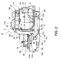
- FIG. 2 is a side view showing the internal mechanical assembly of the check processing device 1 with the outside case 2 removed.
- FIG. 3 is an oblique side view of the internal mechanical assembly from a point of view slightly towards the back
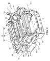
- FIG. 4 is an oblique side view of the internal mechanical assembly from a position at the front.
- the internal mechanical assembly 12 of the check processing device 1 includes a main frame 13, and a front printhead unit 14 composing the openable unit 10, back printhead unit 15, and platen lever unit 16 supported on the main frame 13.
- the front printhead unit 14 and back printhead unit 15 are disposed in opposition with the vertical transportation path part 5c where the media transportation path 5 extends to the top of the printer therebetween and the front printhead unit 14 positioned on the side towards the front of the printer. That is, the front printhead unit 14 and the back printhead unit 15 are disposed on opposing sides with respect to the vertical transportation path part 5c.
- the front printhead unit 14 and main frame 13 are disposed in opposition with the horizontal transportation path part 5a that extends straight from the front toward the back of the printer, and the curved transportation path part 5b that curves upward to the vertical transportation path part 5c, therebetween, and the front printhead unit 14 positioned on the side to the top of the printer.
- the front printhead unit 14 and the main frame 13 are disposed on opposing sides with respect to the horizontal transportation path part 5a.
- the front printhead unit 14 is supported on the main frame 13 so that the front printhead unit 14 can pivot forward and open on the first pivot axis CL1 at the front bottom end thereof.
- the back printhead unit 15 is supported on the main frame 13 so that the back printhead unit 15 can slide in the front-back direction of the printer.
- a magnetic head 17 used to read the magnetic ink characters that are printed on checks is disposed to the horizontal transportation path part 5a of the media transportation path 5.
- the magnetic head 17 is disposed on the top side of the horizontal transportation path part 5a with the magnetic gap facing down.
- the back printhead 18 and opposing back platen 19 for printing on the back side of checks are disposed at the bottom side of the vertical transportation path part 5c of the media transportation path 5 with the vertical transportation path part 5c therebetween.
- the back printhead 18 can be a serial impact dot matrix (SIDM) printhead that prints by driving recording wires against an ink ribbon to transfer ink from the ink ribbon onto the check.
- SIDM serial impact dot matrix
- the back printhead 18 is disposed to the back printhead unit 15 located on the back side of the vertical transportation path part 5c, and the back platen 19 is disposed to the front printhead unit 14.
- the front printhead 20 and opposing front platen 21 for printing on the front side of checks are disposed to the top part of the vertical transportation path part 5c with the vertical transportation path part 5c therebetween.
- the front printhead 20 can also be an SIDM printhead, and is disposed to the front printhead unit 14.
- the front platen 21 is disposed to the platen lever unit 16.
- a pair of media transportation rollers 22, 23 that convey checks passed the reading position of the magnetic head 17 are disposed in contact with each other where the horizontal transportation path part 5a and curved transportation path part 5b join.
- a pair of first and second media transportation rollers 24, 25 that convey checks are disposed in contact with each other at a position approximately centered between the back printhead 18 and the front printhead 20 on the vertical transportation path part 5c.
- the first media transportation roller 24 is positioned on the side to the front of the printer and is disposed freely rotatably to the front printhead unit 14.
- the second media transportation roller 25 is positioned on the side to the back of the printer, and is disposed freely rotatably to the platen lever unit 16.
- An ink ribbon cassette loading unit 27 to which an ink ribbon cassette 26 storing an ink ribbon can be removably installed is disposed to the front printhead unit 14. Note that the ink ribbon cassette 26 is not shown in FIG. 4 .
- the ink ribbon (not shown in the figure) delivered from the loaded ink ribbon cassette 26 is set passing between the front printhead 20 and front platen 21.
- An ink ribbon cassette loading unit 29 to which an ink ribbon cassette 28 can be removably installed is similarly disposed to the back printhead unit 15.
- the ink ribbon (not shown in the figure) delivered from this ink ribbon cassette 28 is set passing between the back printhead 18 and back platen 19.
- the platen lever unit 16 includes left and right platen levers 31 and 32 disposed on opposite sides of the printer width, and a connecting plate 33 that spans between the tops of these platen levers 31, 32 widthwise to the printer.
- the connecting plate 33 has a constant width and is disposed facing the front of the printer.
- the front platen 21 is attached to the surface of the connecting plate 33 facing the front of the printer opposite the printing surface of the front printhead 20.
- each platen lever 31, 32 is L-shaped with a horizontal arm 31a of a constant width extending straight in the front-back direction of the printer, and a vertical arm 31b of a constant width that bends substantially perpendicularly from the back end of the horizontal arm 31a and extends straight up.
- the horizontal arms 31a are disposed on the opposite sides of the main frame 13 widthwise to the printer below the front printhead unit 14, and the ends thereof at the front of the printer are attached to the main frame 13 so that the horizontal arms 31a can pivot up and down on a pivot shaft 34 extending widthwise to the printer.
- the vertical arms 31b are disposed on opposite sides of the back printhead unit 15 widthwise to the printer at positions behind the vertical transportation path part 5c of the media transportation path 5.
- the second media transportation roller 25 extends widthwise to the printer between the vertical arms 31b at a position below the connecting plate 33.
- the other platen lever 32 is identically configured and further description thereof is thus omitted.
- a lever tension spring 35 is mounted between the left and right platen levers 31, 32 and the main frame 13. Referring to FIG. 2 and using platen lever 31 by way of example, the lever tension spring 35 spans between a spring catch 31c formed on the bottom end of the vertical arm 31b, and a spring catch 15a formed at a position on the main frame 13 above and behind the spring catch 31c.
- the platen lever unit 16 is pulled in a direction pivoting upward on the pivot shaft 34 by the spring force of the lever tension spring 35, causing the second media transportation roller 25 mounted thereon to contact the first media transportation roller 24 on the front side of the printer with specific pressure.
- Another tension spring is identically disposed on the side of the other platen lever 32.
- the lever tension spring 35 may be mounted between the left and right platen levers 31, 32 and the back printhead unit 15 so that the lever tension spring 35 according to a modified embodiment may span between a spring catch 31c formed on the bottom end of the vertical arm 31b, and a spring catch formed at a position on the back printhead unit 15 above and behind the spring catch 31c.
- the platen lever unit 16 can then also be pulled in a direction pivoting upward on the pivot shaft 34 by the spring force of the lever tension spring 35, causing the second media transportation roller 25 mounted thereon to contact the first media transportation roller 24 on the front side of the printer with specific pressure.
- Another tension spring may then also identically disposed on the side of the other platen lever 32.
- a stop 15b that protrudes to the outside is formed on the left side of the back printhead unit 15.
- the stop 15b and the back edge 31d of the vertical arm 31b of the platen lever 31 are held in contact with each other by the spring force of the lever tension spring 35.
- the platen lever 32 on the other side is configured the same way.
- the back printhead unit 15 is pulled toward the front of the printer by unit tension springs 36, which are disposed applying tension in the front-back direction of the printer on opposite sides of the printer width.
- unit tension springs 36 which are disposed applying tension in the front-back direction of the printer on opposite sides of the printer width.
- the ends of the unit tension springs 36 at the back of the printer are held on spring catches 15c formed on the left and right sides of the back printhead unit 15, and the ends at the front side of the printer are held on spring catches 13a formed on the left and right sides of the main frame 13.
- the back printhead unit 15 is thus pushed to the platen lever unit 16 through the intervening left and right stops 15b by the spring force of these unit tension springs 36.
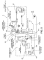
- FIG. 5 describes the parts associated with the platen gap adjustment mechanism of the check processing device 1.
- the platen gap adjustment mechanism of the front printhead 20 and back printhead 18 is described below referring particularly to FIG. 5 .
- the second media transportation roller 25 mounted on the platen lever unit 16 is pushed to the first media transportation roller 24 mounted on the front printhead unit 14 by the lever tension spring 35 at nip point C.
- Contact between the first media transportation roller 24 and second media transportation roller 25 thus determines the position of the back printhead unit 15 relative to the platen lever unit 16, the position of the front printhead 20 on the front printhead unit 14 relative to the front platen 21 on the platen lever unit 16, and thus determines the platen gap of the front printhead 20.
- the back printhead unit 15 is pressed by the unit tension spring 36 at point B against the platen lever unit 16, which is positioned to the front printhead unit 14, and the relative positions thereof are determined by this contact between the platen lever unit 16 and back printhead unit 15.
- the position of the back printhead unit 15 relative to the front printhead unit 14, the position of the back printhead 18 on the back printhead unit 15 relative to the back platen 19 on the front printhead unit 14, and the platen gap of the back printhead 18 are determined by means of the intervening platen lever unit 16.
- the platen gap on the front printhead 20 side is thus adjusted between the front printhead unit 14 and platen lever unit 16, and the platen gap on the back printhead 18 side is adjusted between the front printhead unit 14 and back printhead unit 15.
- the gap between the front printhead unit 14 and back printhead unit 15 can therefore be easily adjusted compared with adjusting both platen gaps.
- the other two units are also displaced accordingly.
- the platen lever unit 16 moves following the front printhead unit 14
- the back printhead unit 15 moves following the displacement of the platen lever unit 16. Because the relative positions of these three units therefore remain constant, the platen gap between the front printhead 20 and front platen 21, and the platen gap between the back printhead 18 and back platen 19, also remain constant, and resistance to external disruption of the platen gap can be improved.
- the positions of the front printhead unit 14 and platen lever unit 16 relative to the other are also determined by contact between the first media transportation roller 24 and second media transportation roller 25.
- the gap between these rollers 24, 25 changes according to the thickness of the conveyed check (embodying a recording medium in this embodiment).
- the position of the platen lever unit 16 relative to the front printhead unit 14 determined by contact between these rollers 24, 25 thus changes, and the position of the back printhead unit 15 determined by the platen lever unit 16 also changes.
- the platen gaps of both printheads 18 and 20 therefore change according to the thickness of the conveyed check, and the distance between the head units and the recording medium can be held to a specific value or more.
- a pivot member that can rotate on a pivot point A is used as the platen lever unit 16, and the platen lever unit 16 and back printhead unit 15 are pushed together by the spring force of the lever tension spring 35. Because this configuration can therefore suppress play between the platen lever unit 16 and back printhead unit 15, it is also effective for holding a constant platen gap.
- the nip point C is positioned substantially centered between the front printhead 20 and back printhead 18 on opposite sides of the nip point C. If the distance in the transportation direction from the nip point C to the front printhead 20 differs greatly from the distance from the nip point C to the back printhead 18, the platen gap on the front printhead 20 side and the platen gap on the back printhead 18 side will differ greatly from the opening between the first and second transportation rollers 24, 25 that is created by the thickness of the check. However, by disposing the front printhead 20 and back printhead 18 proximally to the downstream and upstream sides of the nip point C in the transportation direction, the difference in the change between both platen gaps caused by the thickness of the check can be reduced.
- the front printhead 20 and back printhead 18 in this embodiment of the invention are dot impact heads, and ink ribbons must be respectively set between the front printhead 20 and front platen 21 and between the back printhead 18 and back platen 19. Because the back printhead 18 can slide in the direction between the front and back of the printer, the gap between the front printhead 20 and front platen 21 and the gap between the back printhead 18 and back platen 19 can be increased by sliding the back printhead 18 toward the back against the force of the spring, and the ink ribbons can therefore be easily set in these gaps.
- the embodiment described above uses a platen lever unit to position the back printhead unit relative to the front printhead unit.
- a configuration rendering the platen lever unit and back printhead unit in unison is also conceivable.
- the front printhead, first media transportation roller, and back platen are mounted on the front printhead unit.
- the front platen is mounted at a position opposite the front printhead on the back printhead unit
- the second media transportation roller is mounted at a position where it can contact the first media transportation roller
- the back printhead unit is supported on the main frame so that it can move toward and away from the first media transportation roller.
- the back printhead unit is urged toward the first media transportation roller, and the second media transportation roller is pressed against the first media transportation roller, by a tension spring or other urging member.
- the back printhead unit can move, the second media transportation roller mounted on the back printhead unit is pushed against the first media transportation roller mounted on the stationary front printhead unit by an urging member, and the relative positions of both units are determined by the first and second media transportation rollers.
- both units are displaced by an external force, for example, the back printhead unit side moves according to this displacement, contact between the first media transportation roller and second media transportation roller is sustained by the urging force of the urging member, the relative positions of both units are held constant, and resistance to external disturbance of the platen gaps of the front and back printheads is therefore improved.
- the relative positions of the front printhead unit and back printhead unit are also determined by contact between the first media transportation roller and second media transportation roller.
- the gap between these rollers changes according to the thickness of the conveyed recording medium.
- the relative position of the front printhead unit to the back printhead unit that is determined by contact between these rollers therefore also changes.
- the gap between the front printhead on the front printhead unit side and the front platen on the back printhead unit side, and the gap between the back printhead on the back printhead unit side and the back platen on the front printhead unit side change according to the thickness of the conveyed recording medium.
- the platen gaps of both printheads can therefore change according to the thickness of the conveyed recording medium.
- An L-shaped arm unit is used as the platen lever unit in the foregoing embodiment, but arm units with different shapes can be used instead.
- a platen lever unit that slides in the front-back direction of the printer instead of pivoting could also be used.
- the front and back printheads are serial impact dot matrix printheads in the foregoing embodiment, but inkjet heads can be used instead.
Landscapes
- Handling Of Sheets (AREA)
- Dot-Matrix Printers And Others (AREA)
- Common Mechanisms (AREA)
Abstract
Description
- The present invention relates to a printer that has plural printhead sets for printing on both sides of checks or other recording media, and relates more particularly to a printer having a mechanism that can suitably set the platen gap for each printhead assembly.
- Printers of this type are described as a media processing device in Japanese Unexamined Patent Appl. Pub.
JP-A-2000-43339 JP-A-2010-20809 - The front printhead and back printhead that are used to respectively print on the front and back sides of checks or other recording media are mounted on frame members located on opposite sides of the recording medium transportation path. The platen that defines the printing position of the front printhead is mounted on a frame member on the same side as the back printhead, and the platen for the back printhead is similarly mounted on the frame member on the same side as the front printhead.
- The platen gap of both printheads is typically narrow at 0.5 mm or less, and precisely disposing the two printheads and platens mounted on different frame members so that such a precise, narrow gap can be achieved is not as simple as when there is only a single printhead and platen. More particularly, an external force that displaces both frame members can easily change both platen gaps, and adjusting the platen gaps is more difficult than when there is only one platen gap to be adjusted.
- In addition, when the gap between the printhead and platen is constant and media of different thicknesses are conveyed, the gap between the printhead and the printing surface of the recording medium changes, and problems such as a drop in print quality can result. A problem with the related art is that adjusting the platen gap of both printheads according to the thickness of the recording medium is not possible.
- A printer according to the present invention has a platen gap adjustment mechanism that can maintain a constant platen gap at plural locations.
- A first aspect of the invention is a printer having a first printhead unit on which a first printhead, a first media transportation roller, and a second platen are disposed; a second printhead unit that can move in a direction toward and away from the first media transportation roller, and on which a first platen is disposed at a position opposable to the first printhead, a second media transportation roller is disposed at a position where it can contact the first media transportation roller (in particular, the second media transportation roller may be movably disposed at a position such that it can come in contact with the first media transportation roller), and a second printhead is disposed at a position opposable to the second platen; and urging means, in particular an urging member or a combination of urging members, that urges the second printhead unit toward the first media transportation roller, and presses the second media transportation roller to the first media transportation roller.
- Because the second printhead unit can move, and the second media transportation roller mounted on the second printhead unit is pressed by an urging member to a first media transportation roller disposed on a stationary first printhead unit in this aspect of the invention, the relative positions of the two units are determined by the first and second media transportation rollers. The platen gaps of the first and second printheads are also held constant even when an external force displaces the units because contact between the first media transportation roller and second media transportation roller is held by the urging force of the urging member and the relative position of both units is held constant.
- In addition, the gap between the first media transportation roller and second media transportation roller changes according to the thickness of the recording medium conveyed therebetween. As a result, the relative positions of the first printhead unit and second printhead unit determined by contact between these rollers change. The gap between the first printhead on the first printhead unit side and the first platen on the second printhead unit side therefore changes as the thickness of the conveyed recording medium changes. The gap between the second printhead on the second printhead unit side and the second platen on the first printhead unit side changes similarly. Because the platen gaps change according to the thickness of the conveyed recording medium, the distance between the printhead units and the recording medium can be held to a constant size or greater.
- In another aspect of the invention, the second media transportation roller and second platen can be disposed to a member separate from the second printhead unit, and the first printhead unit and second printhead unit can be positioned by means of said member.
- A printer according to this aspect of the invention has a first printhead unit on which a first printhead, a first media transportation roller, and a second platen are disposed; a moving member that can move in a direction toward and away from the first media transportation roller, and on which a second media transportation roller is disposed at a position where it can come in contact with the first media transportation roller when the moving member moves towards the first media transportation roller, and a first platen is disposed at a position opposable to the first printhead; a first urging member that urges the moving member toward the first media transportation roller, and presses the second media transportation roller to the first media transportation roller; a second printhead unit that can move in a direction toward and away from the first media transportation roller, and on which a second printhead is disposed at a position opposable to the second platen; and a second urging member that urges the second printhead unit toward the first media transportation roller, and presses the second printhead unit to the moving member.
- In this aspect of the invention the second media transportation roller disposed to the moving member is pressed by the first urging member to the first media transportation roller disposed to the first printhead unit. Contact between the first media transportation roller and second media transportation roller determines the position of the first printhead unit relative to the moving member, determines the position of the first printhead disposed to the first printhead unit relative to the first platen disposed to the moving member, and determines the platen gap of the first printhead.
- The second printhead unit is pressed by the second urging member to the moving member positioned to the first printhead unit, and the relative positions thereof are determined by contact between the moving member and the second printhead unit. The relative positions of the first printhead unit and second printhead unit, the position of the second printhead disposed to the second printhead unit relative to the second platen disposed to the first printhead unit, and the platen gap of the second printhead, are thus determined by means of the intervening moving member.
- The platen gap on the first printhead side is thus adjusted between the first printhead unit and the moving member, and the platen gap on the second printhead side is adjusted between the first printhead unit and second printhead unit. The platen gaps can therefore be adjusted more easily using three members than when the first printhead unit and second printhead unit are used to adjust the platen gaps therebetween.
- Furthermore, when the first printhead unit, moving member, or second printhead unit is displaced by external force, for example, the other two also move and are displaced accordingly. For example, if the first printhead unit is displaced, the moving member follows the movement of the first printhead unit, and the second printhead unit moves according to the displacement of the moving member. The relative positions between the three components are therefore always held constant, and the platen gap determined by the first printhead and the first platen, and the platen gap determined by the second printhead and the second platen, are held constant.
- The first printhead unit and moving member are positioned relative to each other by contact between the first media transportation roller and second media transportation roller. The gap between these rollers changes according to the thickness of the conveyed recording medium. As a result, the position of the moving member relative to the first printhead unit that is determined by contact between these rollers changes, and the position of the second printhead unit determined by the moving member also changes. The gap between the first printhead on the first printhead unit side and the first platen on the moving member side therefore changes, and the gap between the second printhead on the second printhead unit side and the second platen on the first printhead unit side changes, according to the thickness of the conveyed recording medium. Because the platen gap thus increases according to the thickness of the conveyed recording medium, the distance between the printhead units and the recording medium can be held to a specific value or greater.
- In another aspect of the invention, a pivot member that can rotate on a predetermined pivot point can be used as the moving member, and a tension spring connected between the pivot member and the second printhead unit or a main frame of the printer can be used as the first urging member. By suitably setting the positions where the tension spring is mounted and the shape of the pivot member, the moving member and second printhead unit can be held pressed together by the force of the tension spring, and play therebetween can be suppressed.
- Further preferably in another aspect of the invention, when seen along the transportation direction of the recording medium passing the nip point of the first media transportation roller and second media transportation roller, one of the first printhead and second printhead is positioned on the upstream side in the transportation direction and the other is positioned on the downstream side in the transportation direction with the nip point therebetween.
If the difference of the distance in the transportation direction from the nip point to the first printhead and the distance from the nip point to the second printhead differ greatly, the platen gap on the first printhead side and the platen gap on the second printhead side will differ greatly relative to the opening created between the first and second media transportation rollers by the thickness of the recording medium. The difference in the platen gaps to the recording medium thickness can be reduced by disposing the first and second printheads upstream and downstream from the nip point in the transportation direction. - Further preferably in a printer according to another aspect of the invention, the first printhead and second printhead are dot impact heads, and the first printhead unit and second printhead unit each have an ink ribbon cassette loading unit.
Because the second printhead unit can move and the gap between the first printhead and the first platen, and the gap between the second printhead and the second platen, increase when the second printhead unit is forcibly moved in the direction away from the first printhead unit side, the ink ribbon can be easily set in these gaps. - In a printer according to the invention, a second media transportation roller disposed to a movable second printhead unit is pressed against a first media transportation roller on the first printhead unit side, thereby determin ing the relative positions therebetween. By maintaining contact between the first and second media transportation rollers by means of an urging member, the platen gaps of the first printhead and second printhead can be held constant, and resistance to external disturbance of the platen gaps can be improved. In addition, because the gap between the first and second media transportation rollers changes according to the thickness of the conveyed recording medium, and the platen gaps of the first and second printheads change, the platen gap increases according to the thickness of the conveyed recording medium, and the distance between the printhead units and recording medium can be held to a constant gap or greater.
Other objects and attainments together with a fuller understanding of the invention will become apparent and appreciated by referring to the following description and claims taken in conjunction with the accompanying drawings. -
-
FIG. 1 is an external oblique view of a check processing device according to a preferred embodiment of the invention. -
FIG. 2 is a side view showing the internal mechanical assembly of the check processing device. -
FIG. 3 is an oblique view of the internal mechanical assembly of the check processing device. -
FIG. 4 is an oblique view of the internal mechanical assembly of the check processing device. -
FIG. 5 describes the platen gap adjustment mechanism of the check processing device. - A check processing device (printer) according to a preferred embodiment of the present invention is described below with reference to the accompanying figures.
-
FIG. 1 is an external oblique view of a check processing device. The check processing device 1 has a basically rectangular box-like outside case 2. Amedia insertion opening 3 for inserting a check (not shown in the figure) as a recording medium is disposed with a specific width widthwise to the printer on the front left side of the outside case 2.
Amedia exit 4 from which the processed checks can be discharged is disposed with a specific width widthwise to the printer in the top of the outside case 2 in the middle between the front and back of the printer.
Amedia transportation path 5 through which the checks can be conveyed is formed between themedia insertion opening 3 and themedia exit 4. Themedia transportation path 5 extends from themedia insertion opening 3 toward the back of the printer and then curves and extends to the top. Themedia transportation path 5 is also open to the left side of the outside case 2. - The top of the outside case 2 in front of the
media exit 4 is covered by afront cover 6. An operating panel 7 is disposed at the front of thefront cover 6. Acompartment 8 is disposed and acover 9 for opening and closing thecompartment 8 is attached at the back of the top of the outside case 2. Thecover 9 is pivotably attached at the back end thereof to the outside case 2. - The part of the check processing device 1 covered by the
front cover 6 is anopenable unit 10, which can open forward pivoting on a first pivot axis CL1 that extends widthwise to the printer at the front bottom part of theopenable unit 10. Opening theopenable unit 10 opens themedia transportation path 5 rendered between theopenable unit 10 and the printer assembly. Theopenable unit 10 can be opened by manually pulling an operatinglever 11 of which the operatingend 11a is exposed at the top right part of theopenable unit 10 forward. -
FIG. 2 is a side view showing the internal mechanical assembly of the check processing device 1 with the outside case 2 removed.FIG. 3 is an oblique side view of the internal mechanical assembly from a point of view slightly towards the back, andFIG. 4 is an oblique side view of the internal mechanical assembly from a position at the front.
As shown in these figures, the internalmechanical assembly 12 of the check processing device 1 includes amain frame 13, and afront printhead unit 14 composing theopenable unit 10,back printhead unit 15, andplaten lever unit 16 supported on themain frame 13. - The
front printhead unit 14 and backprinthead unit 15 are disposed in opposition with the verticaltransportation path part 5c where themedia transportation path 5 extends to the top of the printer therebetween and thefront printhead unit 14 positioned on the side towards the front of the printer. That is, thefront printhead unit 14 and theback printhead unit 15 are disposed on opposing sides with respect to the verticaltransportation path part 5c. Thefront printhead unit 14 andmain frame 13 are disposed in opposition with the horizontaltransportation path part 5a that extends straight from the front toward the back of the printer, and the curvedtransportation path part 5b that curves upward to the verticaltransportation path part 5c, therebetween, and thefront printhead unit 14 positioned on the side to the top of the printer. That is, thefront printhead unit 14 and themain frame 13 are disposed on opposing sides with respect to the horizontaltransportation path part 5a.
Thefront printhead unit 14 is supported on themain frame 13 so that thefront printhead unit 14 can pivot forward and open on the first pivot axis CL1 at the front bottom end thereof. Theback printhead unit 15 is supported on themain frame 13 so that theback printhead unit 15 can slide in the front-back direction of the printer. - A
magnetic head 17 used to read the magnetic ink characters that are printed on checks is disposed to the horizontaltransportation path part 5a of themedia transportation path 5. Themagnetic head 17 is disposed on the top side of the horizontaltransportation path part 5a with the magnetic gap facing down. - The
back printhead 18 and opposing back platen 19 for printing on the back side of checks are disposed at the bottom side of the verticaltransportation path part 5c of themedia transportation path 5 with the verticaltransportation path part 5c therebetween. Theback printhead 18 can be a serial impact dot matrix (SIDM) printhead that prints by driving recording wires against an ink ribbon to transfer ink from the ink ribbon onto the check. Theback printhead 18 is disposed to theback printhead unit 15 located on the back side of the verticaltransportation path part 5c, and theback platen 19 is disposed to thefront printhead unit 14. - The
front printhead 20 and opposingfront platen 21 for printing on the front side of checks are disposed to the top part of the verticaltransportation path part 5c with the verticaltransportation path part 5c therebetween. Like theback printhead 18, thefront printhead 20 can also be an SIDM printhead, and is disposed to thefront printhead unit 14. Thefront platen 21 is disposed to theplaten lever unit 16. - A pair of
media transportation rollers magnetic head 17 are disposed in contact with each other where the horizontaltransportation path part 5a and curvedtransportation path part 5b join. A pair of first and secondmedia transportation rollers back printhead 18 and thefront printhead 20 on the verticaltransportation path part 5c. The firstmedia transportation roller 24 is positioned on the side to the front of the printer and is disposed freely rotatably to thefront printhead unit 14. The secondmedia transportation roller 25 is positioned on the side to the back of the printer, and is disposed freely rotatably to theplaten lever unit 16. - An ink ribbon
cassette loading unit 27 to which anink ribbon cassette 26 storing an ink ribbon can be removably installed is disposed to thefront printhead unit 14. Note that theink ribbon cassette 26 is not shown inFIG. 4 . The ink ribbon (not shown in the figure) delivered from the loadedink ribbon cassette 26 is set passing between thefront printhead 20 andfront platen 21.
An ink ribboncassette loading unit 29 to which anink ribbon cassette 28 can be removably installed is similarly disposed to theback printhead unit 15. The ink ribbon (not shown in the figure) delivered from thisink ribbon cassette 28 is set passing between theback printhead 18 and backplaten 19. - The
platen lever unit 16 includes left and right platen levers 31 and 32 disposed on opposite sides of the printer width, and a connectingplate 33 that spans between the tops of these platen levers 31, 32 widthwise to the printer. The connectingplate 33 has a constant width and is disposed facing the front of the printer. Thefront platen 21 is attached to the surface of the connectingplate 33 facing the front of the printer opposite the printing surface of thefront printhead 20. - The left and right platen levers 31, 32 are identically shaped and disposed symmetrically left and right. Using
platen lever 31 by way of example, eachplaten lever horizontal arm 31a of a constant width extending straight in the front-back direction of the printer, and avertical arm 31b of a constant width that bends substantially perpendicularly from the back end of thehorizontal arm 31a and extends straight up.
Thehorizontal arms 31a are disposed on the opposite sides of themain frame 13 widthwise to the printer below thefront printhead unit 14, and the ends thereof at the front of the printer are attached to themain frame 13 so that thehorizontal arms 31a can pivot up and down on apivot shaft 34 extending widthwise to the printer.
Thevertical arms 31b are disposed on opposite sides of theback printhead unit 15 widthwise to the printer at positions behind the verticaltransportation path part 5c of themedia transportation path 5.
The secondmedia transportation roller 25 extends widthwise to the printer between thevertical arms 31b at a position below the connectingplate 33.
Theother platen lever 32 is identically configured and further description thereof is thus omitted. - A
lever tension spring 35 is mounted between the left and right platen levers 31, 32 and themain frame 13. Referring toFIG. 2 and usingplaten lever 31 by way of example, thelever tension spring 35 spans between aspring catch 31c formed on the bottom end of thevertical arm 31b, and aspring catch 15a formed at a position on themain frame 13 above and behind thespring catch 31c. Theplaten lever unit 16 is pulled in a direction pivoting upward on thepivot shaft 34 by the spring force of thelever tension spring 35, causing the secondmedia transportation roller 25 mounted thereon to contact the firstmedia transportation roller 24 on the front side of the printer with specific pressure.
Another tension spring is identically disposed on the side of theother platen lever 32.
Alternatively, thelever tension spring 35 may be mounted between the left and right platen levers 31, 32 and theback printhead unit 15 so that thelever tension spring 35 according to a modified embodiment may span between aspring catch 31c formed on the bottom end of thevertical arm 31b, and a spring catch formed at a position on theback printhead unit 15 above and behind thespring catch 31c. Theplaten lever unit 16 can then also be pulled in a direction pivoting upward on thepivot shaft 34 by the spring force of thelever tension spring 35, causing the secondmedia transportation roller 25 mounted thereon to contact the firstmedia transportation roller 24 on the front side of the printer with specific pressure. Another tension spring may then also identically disposed on the side of theother platen lever 32. - A
stop 15b that protrudes to the outside is formed on the left side of theback printhead unit 15. Thestop 15b and theback edge 31d of thevertical arm 31b of theplaten lever 31 are held in contact with each other by the spring force of thelever tension spring 35.
Theplaten lever 32 on the other side is configured the same way. - The
back printhead unit 15 is pulled toward the front of the printer by unit tension springs 36, which are disposed applying tension in the front-back direction of the printer on opposite sides of the printer width. As shown inFIG. 2 , the ends of the unit tension springs 36 at the back of the printer are held onspring catches 15c formed on the left and right sides of theback printhead unit 15, and the ends at the front side of the printer are held onspring catches 13a formed on the left and right sides of themain frame 13. Theback printhead unit 15 is thus pushed to theplaten lever unit 16 through the intervening left andright stops 15b by the spring force of these unit tension springs 36. -
FIG. 5 describes the parts associated with the platen gap adjustment mechanism of the check processing device 1. The platen gap adjustment mechanism of thefront printhead 20 and backprinthead 18 is described below referring particularly toFIG. 5 .
In this embodiment of the invention the secondmedia transportation roller 25 mounted on theplaten lever unit 16 is pushed to the firstmedia transportation roller 24 mounted on thefront printhead unit 14 by thelever tension spring 35 at nip point C. Contact between the firstmedia transportation roller 24 and secondmedia transportation roller 25 thus determines the position of theback printhead unit 15 relative to theplaten lever unit 16, the position of thefront printhead 20 on thefront printhead unit 14 relative to thefront platen 21 on theplaten lever unit 16, and thus determines the platen gap of thefront printhead 20. - The
back printhead unit 15 is pressed by theunit tension spring 36 at point B against theplaten lever unit 16, which is positioned to thefront printhead unit 14, and the relative positions thereof are determined by this contact between theplaten lever unit 16 and backprinthead unit 15. As a result, the position of theback printhead unit 15 relative to thefront printhead unit 14, the position of theback printhead 18 on theback printhead unit 15 relative to theback platen 19 on thefront printhead unit 14, and the platen gap of theback printhead 18 are determined by means of the interveningplaten lever unit 16. - The platen gap on the
front printhead 20 side is thus adjusted between thefront printhead unit 14 andplaten lever unit 16, and the platen gap on theback printhead 18 side is adjusted between thefront printhead unit 14 and backprinthead unit 15. The gap between thefront printhead unit 14 and backprinthead unit 15 can therefore be easily adjusted compared with adjusting both platen gaps. - When the
front printhead unit 14,platen lever unit 16, or backprinthead unit 15 is displaced by an external force, the other two units are also displaced accordingly. For example, when thefront printhead unit 14 is displaced, theplaten lever unit 16 moves following thefront printhead unit 14, and theback printhead unit 15 moves following the displacement of theplaten lever unit 16. Because the relative positions of these three units therefore remain constant, the platen gap between thefront printhead 20 andfront platen 21, and the platen gap between theback printhead 18 and backplaten 19, also remain constant, and resistance to external disruption of the platen gap can be improved. - The positions of the
front printhead unit 14 andplaten lever unit 16 relative to the other are also determined by contact between the firstmedia transportation roller 24 and secondmedia transportation roller 25. The gap between theserollers platen lever unit 16 relative to thefront printhead unit 14 determined by contact between theserollers back printhead unit 15 determined by theplaten lever unit 16 also changes. As a result, the gap between thefront printhead 20 on thefront printhead unit 14 side and thefront platen 21 on theplaten lever unit 16 side, and the gap between theback printhead 18 on theback printhead unit 15 side and theback platen 19 on thefront printhead unit 14 side, change according to the thickness of the conveyed check. The platen gaps of bothprintheads - In addition, a pivot member that can rotate on a pivot point A is used as the
platen lever unit 16, and theplaten lever unit 16 and backprinthead unit 15 are pushed together by the spring force of thelever tension spring 35. Because this configuration can therefore suppress play between theplaten lever unit 16 and backprinthead unit 15, it is also effective for holding a constant platen gap. - Next, when seen along the transportation direction of a check passing the nip point C of the first
media transportation roller 24 and secondmedia transportation roller 25, the nip point C is positioned substantially centered between thefront printhead 20 and backprinthead 18 on opposite sides of the nip point C. If the distance in the transportation direction from the nip point C to thefront printhead 20 differs greatly from the distance from the nip point C to theback printhead 18, the platen gap on thefront printhead 20 side and the platen gap on theback printhead 18 side will differ greatly from the opening between the first andsecond transportation rollers front printhead 20 and backprinthead 18 proximally to the downstream and upstream sides of the nip point C in the transportation direction, the difference in the change between both platen gaps caused by the thickness of the check can be reduced. - In addition, the
front printhead 20 and backprinthead 18 in this embodiment of the invention are dot impact heads, and ink ribbons must be respectively set between thefront printhead 20 andfront platen 21 and between theback printhead 18 and backplaten 19. Because theback printhead 18 can slide in the direction between the front and back of the printer, the gap between thefront printhead 20 andfront platen 21 and the gap between theback printhead 18 and back platen 19 can be increased by sliding theback printhead 18 toward the back against the force of the spring, and the ink ribbons can therefore be easily set in these gaps. - The embodiment described above uses a platen lever unit to position the back printhead unit relative to the front printhead unit. A configuration rendering the platen lever unit and back printhead unit in unison is also conceivable.
In a printer thus configured, the front printhead, first media transportation roller, and back platen are mounted on the front printhead unit. In addition, the front platen is mounted at a position opposite the front printhead on the back printhead unit, the second media transportation roller is mounted at a position where it can contact the first media transportation roller, and the back printhead unit is supported on the main frame so that it can move toward and away from the first media transportation roller. In addition, the back printhead unit is urged toward the first media transportation roller, and the second media transportation roller is pressed against the first media transportation roller, by a tension spring or other urging member. - In a printer thus comprised, the back printhead unit can move, the second media transportation roller mounted on the back printhead unit is pushed against the first media transportation roller mounted on the stationary front printhead unit by an urging member, and the relative positions of both units are determined by the first and second media transportation rollers. When both units are displaced by an external force, for example, the back printhead unit side moves according to this displacement, contact between the first media transportation roller and second media transportation roller is sustained by the urging force of the urging member, the relative positions of both units are held constant, and resistance to external disturbance of the platen gaps of the front and back printheads is therefore improved.
- The relative positions of the front printhead unit and back printhead unit are also determined by contact between the first media transportation roller and second media transportation roller. The gap between these rollers changes according to the thickness of the conveyed recording medium. The relative position of the front printhead unit to the back printhead unit that is determined by contact between these rollers therefore also changes. As a result, the gap between the front printhead on the front printhead unit side and the front platen on the back printhead unit side, and the gap between the back printhead on the back printhead unit side and the back platen on the front printhead unit side, change according to the thickness of the conveyed recording medium. The platen gaps of both printheads can therefore change according to the thickness of the conveyed recording medium.
- An L-shaped arm unit is used as the platen lever unit in the foregoing embodiment, but arm units with different shapes can be used instead. A platen lever unit that slides in the front-back direction of the printer instead of pivoting could also be used.
- The front and back printheads are serial impact dot matrix printheads in the foregoing embodiment, but inkjet heads can be used instead.
- The embodiment described above applies the invention to a check processing device, but the invention can be similarly applied to printers that print on recording media other than checks.
Although the present invention has been described in connection with the preferred embodiments thereof with reference to the accompanying drawings, it is to be noted that various changes and modifications will be apparent to those skilled in the art. Such changes and modifications are to be understood as included within the scope of the present invention as defined by the appended claims, unless they depart therefrom.
Claims (13)
- A printer comprising:a first printhead unit (14) on which a first printhead (20), a first media transportation roller (24), and a second platen (19) are disposed;a second printhead unit (15) that can move in a direction toward and away from the first media transportation roller (24), and on which a first platen (21) is disposed at a position opposable to the first printhead (20), wherein a second media transportation roller (25) is disposed movably at a position such that it can come in contact with the first media transportation roller (24), and a second printhead (18) is disposed at a position opposable to the second platen (19); andurging means being configured to urge the second printhead unit (15) toward the first media transportation roller (24), and to press the second media transportation roller (25) to the first media transportation roller (24).
- The printer according to claim 1, further comprising a moving member (16) that can move in a direction toward and away from the first media transportation roller (24), and on which the second media transportation roller (25) is disposed at a position so that it can come in contact with the first media transportation roller (24) when the moving member (16) moves towards the first media transportation roller (24).
- The printer according to claim 2, wherein
the urging means comprises a first urging member (35) that urges the moving member (16) toward the first media transportation roller (24), and presses the second media transportation roller (25) to the first media transportation roller (24). - The printer according to claim 2 or 3, wherein
the urging means comprises a second urging member (36) that urges the second printhead unit (15) toward the first media transportation roller (24), and presses the second printhead unit (15) to the moving member (16). - The printer described in at least one of claims 2 to 4, wherein the moving member (16) is a pivot member that can rotate on a predetermined pivot point (A).
- The printer described in claim 5, wherein the first urging member (35) is a tension spring connected between the pivot member (31) and the second printhead unit (15) or a main frame (13) of the printer.
- The printer described in at least one of claims 1 to 6, wherein:when seen along the transportation direction of the recording medium passing a nip point (C) of the first media transportation roller (24) and second media transportation roller (25), one of the first printhead (20) and second printhead (18) is positioned on the upstream side in the transportation direction and the other is positioned on the downstream side in the transportation direction with the nip point (C) therebetween.
- The printer described in at least one of claims 1 to 7, wherein:the first printhead (20) and second printhead (18) are dot impact heads; andthe first printhead unit (14) and second printhead unit (15) each have an ink ribbon cassette loading unit (27; 29).
- A printer comprising:a first printhead unit (14) on which a first printhead (20), a first media transportation roller (24), and a second platen (19) are disposed;a moving member (16) that can move in a direction toward and away from the first media transportation roller (24), and on which a second media transportation roller (25) is disposed at a position where it can come in contact with the first media transportation roller (24) when the moving member (16) moves towards the first media transportation roller (24), and a first platen (21) is disposed at a position opposable to the first printhead (14);a first urging member (35) that urges the moving member (16) toward the first media transportation roller (24), and presses the second media transportation roller (25) to the first media transportation roller (24);a second printhead unit (15) that can move in a direction toward and away from the first media transportation roller (24), and on which a second printhead (18) is disposed at a position opposable to the second platen (19); anda second urging member (36) that urges the second printhead unit (15) toward the first media transportation roller (24), and presses the second printhead unit (15) to the moving member (16).
- The printer described in claim 9, wherein the moving member (16) is a pivot member (31) that can rotate on a predetermined pivot point (A).
- The printer described in claim 10, wherein the first urging member (35) is a tension spring connected between the pivot member (31) and the second printhead unit (15) or a main frame (13) of the printer.
- The printer described in at least one of claims 9 to 11, wherein:when seen along the transportation direction of the recording medium passing a nip point (C) of the first media transportation roller (24) and second media transportation roller (25), one of the first printhead (20) and second printhead (18) is positioned on the upstream side in the transportation direction and the other is positioned on the downstream side in the transportation direction with the nip point (C) therebetween.
- The printer described in at least one of claims 9 to 12, wherein:the first printhead (20) and second printhead (18) are dot impact heads; andthe first printhead unit (14) and second printhead unit (15) each have an ink ribbon cassette loading unit (27; 29).
Applications Claiming Priority (1)
| Application Number | Priority Date | Filing Date | Title |
|---|---|---|---|
| JP2010067509A JP2011201017A (en) | 2010-03-24 | 2010-03-24 | Printer |
Publications (3)
| Publication Number | Publication Date |
|---|---|
| EP2368717A2 true EP2368717A2 (en) | 2011-09-28 |
| EP2368717A3 EP2368717A3 (en) | 2014-04-30 |
| EP2368717B1 EP2368717B1 (en) | 2015-11-11 |
Family
ID=44259704
Family Applications (1)
| Application Number | Title | Priority Date | Filing Date |
|---|---|---|---|
| EP11159525.2A Not-in-force EP2368717B1 (en) | 2010-03-24 | 2011-03-24 | Printer |
Country Status (4)
| Country | Link |
|---|---|
| US (1) | US8534940B2 (en) |
| EP (1) | EP2368717B1 (en) |
| JP (1) | JP2011201017A (en) |
| CN (1) | CN102211466B (en) |
Cited By (1)
| Publication number | Priority date | Publication date | Assignee | Title |
|---|---|---|---|---|
| EP2902208A1 (en) * | 2014-01-31 | 2015-08-05 | Funai Electric Co., Ltd. | Printer |
Families Citing this family (2)
| Publication number | Priority date | Publication date | Assignee | Title |
|---|---|---|---|---|
| EP2511100B1 (en) * | 2011-04-11 | 2014-11-05 | Wincor Nixdorf International GmbH | Double-sided printer for printing receipts on thermal paper |
| CN103342046B (en) * | 2013-07-11 | 2016-02-03 | 章珩 | The additional process equipment pasting page of special note endorsement |
Citations (2)
| Publication number | Priority date | Publication date | Assignee | Title |
|---|---|---|---|---|
| JP2000043339A (en) | 1998-07-28 | 2000-02-15 | Seiko Epson Corp | Compound processing equipment |
| JP2010020809A (en) | 2003-02-03 | 2010-01-28 | Seiko Epson Corp | Magnetic ink character reading apparatus and reading processing method thereof |
Family Cites Families (23)
| Publication number | Priority date | Publication date | Assignee | Title |
|---|---|---|---|---|
| JPH0351149A (en) * | 1989-07-20 | 1991-03-05 | Fujitsu General Ltd | thermal transfer printer |
| JPH04282261A (en) * | 1991-03-08 | 1992-10-07 | Brother Ind Ltd | Print gap detection device in print head |
| JPH11286147A (en) * | 1998-04-02 | 1999-10-19 | Nec Yonezawa Ltd | Perfecting mechanism |
| CA2355188C (en) | 1998-12-16 | 2007-11-06 | Silverbrook Research Pty Ltd | A printer for incorporation into consumer electronic (ce) systems with limited access |
| JP2000280576A (en) | 1999-03-29 | 2000-10-10 | Seiko Epson Corp | Printer and control method thereof |
| JP2002234215A (en) * | 2001-02-09 | 2002-08-20 | Casio Comput Co Ltd | Receipt issuing device and program |
| JP2004098625A (en) * | 2002-09-12 | 2004-04-02 | Toshiba Tec Corp | Printer and product information processing device |
| JP4438387B2 (en) | 2003-02-03 | 2010-03-24 | セイコーエプソン株式会社 | Magnetic ink character reader |
| JP2005329563A (en) * | 2004-05-18 | 2005-12-02 | Sanwa Newtec Co Ltd | Thermal printer apparatus |
| JP4720161B2 (en) * | 2004-12-01 | 2011-07-13 | セイコーエプソン株式会社 | Composite processing apparatus and control method thereof |
| JP4735283B2 (en) * | 2005-01-21 | 2011-07-27 | セイコーエプソン株式会社 | Paper sheet processing equipment |
| KR100772378B1 (en) * | 2005-08-09 | 2007-11-01 | 삼성전자주식회사 | Image forming apparatus and printing method employing TFT |
| US20070134039A1 (en) * | 2005-12-08 | 2007-06-14 | Ncr Corporation | Dual-sided thermal printing |
| US8462184B2 (en) * | 2005-12-08 | 2013-06-11 | Ncr Corporation | Two-sided thermal printer control |
| JP2007313848A (en) * | 2006-05-29 | 2007-12-06 | Toshiba Tec Corp | Thermal printer and control method thereof |
| JP4388036B2 (en) * | 2006-06-02 | 2009-12-24 | 東芝テック株式会社 | Duplex printing device |
| US7914218B2 (en) * | 2006-06-29 | 2011-03-29 | Toshiba Tec Kabushiki Kaisha | Thermal printer and printing device |
| DE602007014250D1 (en) * | 2006-06-29 | 2011-06-09 | Ncr Corp | printer |
| CN101663169B (en) * | 2006-12-22 | 2013-06-19 | Ncr公司 | Two-sided thermal print sensing |
| JP4910965B2 (en) * | 2007-09-28 | 2012-04-04 | セイコーエプソン株式会社 | Thermal printer |
| JP5007694B2 (en) | 2008-03-24 | 2012-08-22 | セイコーエプソン株式会社 | Line thermal printer |
| JP2010042513A (en) * | 2008-08-08 | 2010-02-25 | Toshiba Tec Corp | Printer and control method thereof |
| JP2010064269A (en) * | 2008-09-08 | 2010-03-25 | Toshiba Tec Corp | Thermal printer and control method thereof |
-
2010
- 2010-03-24 JP JP2010067509A patent/JP2011201017A/en active Pending
-
2011
- 2011-02-23 US US13/032,707 patent/US8534940B2/en not_active Expired - Fee Related
- 2011-03-22 CN CN201110074021.4A patent/CN102211466B/en active Active
- 2011-03-24 EP EP11159525.2A patent/EP2368717B1/en not_active Not-in-force
Patent Citations (2)
| Publication number | Priority date | Publication date | Assignee | Title |
|---|---|---|---|---|
| JP2000043339A (en) | 1998-07-28 | 2000-02-15 | Seiko Epson Corp | Compound processing equipment |
| JP2010020809A (en) | 2003-02-03 | 2010-01-28 | Seiko Epson Corp | Magnetic ink character reading apparatus and reading processing method thereof |
Cited By (2)
| Publication number | Priority date | Publication date | Assignee | Title |
|---|---|---|---|---|
| EP2902208A1 (en) * | 2014-01-31 | 2015-08-05 | Funai Electric Co., Ltd. | Printer |
| US9216584B2 (en) | 2014-01-31 | 2015-12-22 | Funai Electric Co., Ltd. | Printer |
Also Published As
| Publication number | Publication date |
|---|---|
| JP2011201017A (en) | 2011-10-13 |
| CN102211466A (en) | 2011-10-12 |
| EP2368717A3 (en) | 2014-04-30 |
| US20110236109A1 (en) | 2011-09-29 |
| EP2368717B1 (en) | 2015-11-11 |
| CN102211466B (en) | 2014-12-31 |
| US8534940B2 (en) | 2013-09-17 |
Similar Documents
| Publication | Publication Date | Title |
|---|---|---|
| US10427428B2 (en) | Ink-jet recording apparatus | |
| US11124004B2 (en) | Printing apparatus | |
| EP2042327B1 (en) | Thermal printer | |
| US11440334B2 (en) | Cutter apparatus and printing apparatus | |
| US11006010B2 (en) | Printing apparatus that includes a pivoting display that can be opened and closed | |
| US8287198B2 (en) | Printer | |
| JP5464005B2 (en) | Roll paper printer | |
| US11285743B2 (en) | Printer | |
| US8534940B2 (en) | Printer with moveable first and second print head units | |
| WO1999051443A1 (en) | Printer | |
| US8523465B2 (en) | Printer with multi-curved intermediate transportation path | |
| US8651757B2 (en) | Printer | |
| US8550734B2 (en) | Transportation guide mechanism and recording device having the same | |
| CN1809467B (en) | Printer | |
| KR20030063193A (en) | Printer | |
| JPH11348364A (en) | Printer | |
| JP6201550B2 (en) | Recording device | |
| JP5854105B2 (en) | printer | |
| JP3132531B2 (en) | Paper thickness adjustment device for image forming equipment | |
| JP2011207550A (en) | Roll paper printer |
Legal Events
| Date | Code | Title | Description |
|---|---|---|---|
| PUAI | Public reference made under article 153(3) epc to a published international application that has entered the european phase |
Free format text: ORIGINAL CODE: 0009012 |
|
| AK | Designated contracting states |
Kind code of ref document: A2 Designated state(s): AL AT BE BG CH CY CZ DE DK EE ES FI FR GB GR HR HU IE IS IT LI LT LU LV MC MK MT NL NO PL PT RO RS SE SI SK SM TR |
|
| AX | Request for extension of the european patent |
Extension state: BA ME |
|
| PUAL | Search report despatched |
Free format text: ORIGINAL CODE: 0009013 |
|
| AK | Designated contracting states |
Kind code of ref document: A3 Designated state(s): AL AT BE BG CH CY CZ DE DK EE ES FI FR GB GR HR HU IE IS IT LI LT LU LV MC MK MT NL NO PL PT RO RS SE SI SK SM TR |
|
| AX | Request for extension of the european patent |
Extension state: BA ME |
|
| RIC1 | Information provided on ipc code assigned before grant |
Ipc: B41J 3/60 20060101ALI20140321BHEP Ipc: B41J 25/308 20060101AFI20140321BHEP |
|
| 17P | Request for examination filed |
Effective date: 20141028 |
|
| RBV | Designated contracting states (corrected) |
Designated state(s): AL AT BE BG CH CY CZ DE DK EE ES FI FR GB GR HR HU IE IS IT LI LT LU LV MC MK MT NL NO PL PT RO RS SE SI SK SM TR |
|
| 17Q | First examination report despatched |
Effective date: 20141223 |
|
| GRAP | Despatch of communication of intention to grant a patent |
Free format text: ORIGINAL CODE: EPIDOSNIGR1 |
|
| INTG | Intention to grant announced |
Effective date: 20150618 |
|
| GRAS | Grant fee paid |
Free format text: ORIGINAL CODE: EPIDOSNIGR3 |
|
| GRAA | (expected) grant |
Free format text: ORIGINAL CODE: 0009210 |
|
| AK | Designated contracting states |
Kind code of ref document: B1 Designated state(s): AL AT BE BG CH CY CZ DE DK EE ES FI FR GB GR HR HU IE IS IT LI LT LU LV MC MK MT NL NO PL PT RO RS SE SI SK SM TR |
|
| REG | Reference to a national code |
Ref country code: GB Ref legal event code: FG4D |
|
| REG | Reference to a national code |
Ref country code: CH Ref legal event code: EP |
|
| REG | Reference to a national code |
Ref country code: IE Ref legal event code: FG4D |
|
| REG | Reference to a national code |
Ref country code: AT Ref legal event code: REF Ref document number: 760243 Country of ref document: AT Kind code of ref document: T Effective date: 20151215 |
|
| REG | Reference to a national code |
Ref country code: DE Ref legal event code: R096 Ref document number: 602011021311 Country of ref document: DE |
|
| REG | Reference to a national code |
Ref country code: LT Ref legal event code: MG4D |
|
| REG | Reference to a national code |
Ref country code: NL Ref legal event code: MP Effective date: 20160211 |
|
| REG | Reference to a national code |
Ref country code: FR Ref legal event code: PLFP Year of fee payment: 6 |
|
| REG | Reference to a national code |
Ref country code: AT Ref legal event code: MK05 Ref document number: 760243 Country of ref document: AT Kind code of ref document: T Effective date: 20151111 |
|
| PG25 | Lapsed in a contracting state [announced via postgrant information from national office to epo] |
Ref country code: LT Free format text: LAPSE BECAUSE OF FAILURE TO SUBMIT A TRANSLATION OF THE DESCRIPTION OR TO PAY THE FEE WITHIN THE PRESCRIBED TIME-LIMIT Effective date: 20151111 Ref country code: IS Free format text: LAPSE BECAUSE OF FAILURE TO SUBMIT A TRANSLATION OF THE DESCRIPTION OR TO PAY THE FEE WITHIN THE PRESCRIBED TIME-LIMIT Effective date: 20160311 Ref country code: ES Free format text: LAPSE BECAUSE OF FAILURE TO SUBMIT A TRANSLATION OF THE DESCRIPTION OR TO PAY THE FEE WITHIN THE PRESCRIBED TIME-LIMIT Effective date: 20151111 Ref country code: NL Free format text: LAPSE BECAUSE OF FAILURE TO SUBMIT A TRANSLATION OF THE DESCRIPTION OR TO PAY THE FEE WITHIN THE PRESCRIBED TIME-LIMIT Effective date: 20151111 Ref country code: HR Free format text: LAPSE BECAUSE OF FAILURE TO SUBMIT A TRANSLATION OF THE DESCRIPTION OR TO PAY THE FEE WITHIN THE PRESCRIBED TIME-LIMIT Effective date: 20151111 Ref country code: NO Free format text: LAPSE BECAUSE OF FAILURE TO SUBMIT A TRANSLATION OF THE DESCRIPTION OR TO PAY THE FEE WITHIN THE PRESCRIBED TIME-LIMIT Effective date: 20160211 |
|
| PG25 | Lapsed in a contracting state [announced via postgrant information from national office to epo] |
Ref country code: SE Free format text: LAPSE BECAUSE OF FAILURE TO SUBMIT A TRANSLATION OF THE DESCRIPTION OR TO PAY THE FEE WITHIN THE PRESCRIBED TIME-LIMIT Effective date: 20151111 Ref country code: PL Free format text: LAPSE BECAUSE OF FAILURE TO SUBMIT A TRANSLATION OF THE DESCRIPTION OR TO PAY THE FEE WITHIN THE PRESCRIBED TIME-LIMIT Effective date: 20151111 Ref country code: RS Free format text: LAPSE BECAUSE OF FAILURE TO SUBMIT A TRANSLATION OF THE DESCRIPTION OR TO PAY THE FEE WITHIN THE PRESCRIBED TIME-LIMIT Effective date: 20151111 Ref country code: LV Free format text: LAPSE BECAUSE OF FAILURE TO SUBMIT A TRANSLATION OF THE DESCRIPTION OR TO PAY THE FEE WITHIN THE PRESCRIBED TIME-LIMIT Effective date: 20151111 Ref country code: AT Free format text: LAPSE BECAUSE OF FAILURE TO SUBMIT A TRANSLATION OF THE DESCRIPTION OR TO PAY THE FEE WITHIN THE PRESCRIBED TIME-LIMIT Effective date: 20151111 Ref country code: PT Free format text: LAPSE BECAUSE OF FAILURE TO SUBMIT A TRANSLATION OF THE DESCRIPTION OR TO PAY THE FEE WITHIN THE PRESCRIBED TIME-LIMIT Effective date: 20160311 Ref country code: GR Free format text: LAPSE BECAUSE OF FAILURE TO SUBMIT A TRANSLATION OF THE DESCRIPTION OR TO PAY THE FEE WITHIN THE PRESCRIBED TIME-LIMIT Effective date: 20160212 Ref country code: FI Free format text: LAPSE BECAUSE OF FAILURE TO SUBMIT A TRANSLATION OF THE DESCRIPTION OR TO PAY THE FEE WITHIN THE PRESCRIBED TIME-LIMIT Effective date: 20151111 |
|
| PG25 | Lapsed in a contracting state [announced via postgrant information from national office to epo] |
Ref country code: CZ Free format text: LAPSE BECAUSE OF FAILURE TO SUBMIT A TRANSLATION OF THE DESCRIPTION OR TO PAY THE FEE WITHIN THE PRESCRIBED TIME-LIMIT Effective date: 20151111 |
|
| REG | Reference to a national code |
Ref country code: DE Ref legal event code: R097 Ref document number: 602011021311 Country of ref document: DE |
|
| PG25 | Lapsed in a contracting state [announced via postgrant information from national office to epo] |
Ref country code: BE Free format text: LAPSE BECAUSE OF NON-PAYMENT OF DUE FEES Effective date: 20160331 Ref country code: RO Free format text: LAPSE BECAUSE OF FAILURE TO SUBMIT A TRANSLATION OF THE DESCRIPTION OR TO PAY THE FEE WITHIN THE PRESCRIBED TIME-LIMIT Effective date: 20151111 Ref country code: EE Free format text: LAPSE BECAUSE OF FAILURE TO SUBMIT A TRANSLATION OF THE DESCRIPTION OR TO PAY THE FEE WITHIN THE PRESCRIBED TIME-LIMIT Effective date: 20151111 Ref country code: SM Free format text: LAPSE BECAUSE OF FAILURE TO SUBMIT A TRANSLATION OF THE DESCRIPTION OR TO PAY THE FEE WITHIN THE PRESCRIBED TIME-LIMIT Effective date: 20151111 Ref country code: SK Free format text: LAPSE BECAUSE OF FAILURE TO SUBMIT A TRANSLATION OF THE DESCRIPTION OR TO PAY THE FEE WITHIN THE PRESCRIBED TIME-LIMIT Effective date: 20151111 Ref country code: DK Free format text: LAPSE BECAUSE OF FAILURE TO SUBMIT A TRANSLATION OF THE DESCRIPTION OR TO PAY THE FEE WITHIN THE PRESCRIBED TIME-LIMIT Effective date: 20151111 |
|
| PLBE | No opposition filed within time limit |
Free format text: ORIGINAL CODE: 0009261 |
|
| STAA | Information on the status of an ep patent application or granted ep patent |
Free format text: STATUS: NO OPPOSITION FILED WITHIN TIME LIMIT |
|
| 26N | No opposition filed |
Effective date: 20160812 |
|
| PG25 | Lapsed in a contracting state [announced via postgrant information from national office to epo] |
Ref country code: MC Free format text: LAPSE BECAUSE OF FAILURE TO SUBMIT A TRANSLATION OF THE DESCRIPTION OR TO PAY THE FEE WITHIN THE PRESCRIBED TIME-LIMIT Effective date: 20151111 Ref country code: LU Free format text: LAPSE BECAUSE OF FAILURE TO SUBMIT A TRANSLATION OF THE DESCRIPTION OR TO PAY THE FEE WITHIN THE PRESCRIBED TIME-LIMIT Effective date: 20160324 |
|
| REG | Reference to a national code |
Ref country code: CH Ref legal event code: PL |
|
| PG25 | Lapsed in a contracting state [announced via postgrant information from national office to epo] |
Ref country code: SI Free format text: LAPSE BECAUSE OF FAILURE TO SUBMIT A TRANSLATION OF THE DESCRIPTION OR TO PAY THE FEE WITHIN THE PRESCRIBED TIME-LIMIT Effective date: 20151111 |
|
| REG | Reference to a national code |
Ref country code: IE Ref legal event code: MM4A |
|
| PG25 | Lapsed in a contracting state [announced via postgrant information from national office to epo] |
Ref country code: BE Free format text: LAPSE BECAUSE OF FAILURE TO SUBMIT A TRANSLATION OF THE DESCRIPTION OR TO PAY THE FEE WITHIN THE PRESCRIBED TIME-LIMIT Effective date: 20151111 |
|
| PG25 | Lapsed in a contracting state [announced via postgrant information from national office to epo] |
Ref country code: IE Free format text: LAPSE BECAUSE OF NON-PAYMENT OF DUE FEES Effective date: 20160324 Ref country code: LI Free format text: LAPSE BECAUSE OF NON-PAYMENT OF DUE FEES Effective date: 20160331 Ref country code: CH Free format text: LAPSE BECAUSE OF NON-PAYMENT OF DUE FEES Effective date: 20160331 |
|
| REG | Reference to a national code |
Ref country code: FR Ref legal event code: PLFP Year of fee payment: 7 |
|
| PG25 | Lapsed in a contracting state [announced via postgrant information from national office to epo] |
Ref country code: MT Free format text: LAPSE BECAUSE OF FAILURE TO SUBMIT A TRANSLATION OF THE DESCRIPTION OR TO PAY THE FEE WITHIN THE PRESCRIBED TIME-LIMIT Effective date: 20151111 |
|
| REG | Reference to a national code |
Ref country code: FR Ref legal event code: PLFP Year of fee payment: 8 |
|
| PG25 | Lapsed in a contracting state [announced via postgrant information from national office to epo] |
Ref country code: HU Free format text: LAPSE BECAUSE OF FAILURE TO SUBMIT A TRANSLATION OF THE DESCRIPTION OR TO PAY THE FEE WITHIN THE PRESCRIBED TIME-LIMIT; INVALID AB INITIO Effective date: 20110324 Ref country code: CY Free format text: LAPSE BECAUSE OF FAILURE TO SUBMIT A TRANSLATION OF THE DESCRIPTION OR TO PAY THE FEE WITHIN THE PRESCRIBED TIME-LIMIT Effective date: 20151111 |
|
| PG25 | Lapsed in a contracting state [announced via postgrant information from national office to epo] |
Ref country code: MT Free format text: LAPSE BECAUSE OF FAILURE TO SUBMIT A TRANSLATION OF THE DESCRIPTION OR TO PAY THE FEE WITHIN THE PRESCRIBED TIME-LIMIT Effective date: 20160331 Ref country code: TR Free format text: LAPSE BECAUSE OF FAILURE TO SUBMIT A TRANSLATION OF THE DESCRIPTION OR TO PAY THE FEE WITHIN THE PRESCRIBED TIME-LIMIT Effective date: 20151111 Ref country code: MK Free format text: LAPSE BECAUSE OF FAILURE TO SUBMIT A TRANSLATION OF THE DESCRIPTION OR TO PAY THE FEE WITHIN THE PRESCRIBED TIME-LIMIT Effective date: 20151111 |
|
| PG25 | Lapsed in a contracting state [announced via postgrant information from national office to epo] |
Ref country code: BG Free format text: LAPSE BECAUSE OF FAILURE TO SUBMIT A TRANSLATION OF THE DESCRIPTION OR TO PAY THE FEE WITHIN THE PRESCRIBED TIME-LIMIT Effective date: 20151111 |
|
| PG25 | Lapsed in a contracting state [announced via postgrant information from national office to epo] |
Ref country code: AL Free format text: LAPSE BECAUSE OF FAILURE TO SUBMIT A TRANSLATION OF THE DESCRIPTION OR TO PAY THE FEE WITHIN THE PRESCRIBED TIME-LIMIT Effective date: 20151111 |
|
| PGFP | Annual fee paid to national office [announced via postgrant information from national office to epo] |
Ref country code: DE Payment date: 20240130 Year of fee payment: 14 Ref country code: GB Payment date: 20240201 Year of fee payment: 14 |
|
| PGFP | Annual fee paid to national office [announced via postgrant information from national office to epo] |
Ref country code: IT Payment date: 20240212 Year of fee payment: 14 Ref country code: FR Payment date: 20240213 Year of fee payment: 14 |
|
| REG | Reference to a national code |
Ref country code: DE Ref legal event code: R119 Ref document number: 602011021311 Country of ref document: DE |
|
| GBPC | Gb: european patent ceased through non-payment of renewal fee |
Effective date: 20250324 |
|
| PG25 | Lapsed in a contracting state [announced via postgrant information from national office to epo] |
Ref country code: DE Free format text: LAPSE BECAUSE OF NON-PAYMENT OF DUE FEES Effective date: 20251001 |
|
| PG25 | Lapsed in a contracting state [announced via postgrant information from national office to epo] |
Ref country code: GB Free format text: LAPSE BECAUSE OF NON-PAYMENT OF DUE FEES Effective date: 20250324 |
|
| PG25 | Lapsed in a contracting state [announced via postgrant information from national office to epo] |
Ref country code: IT Free format text: LAPSE BECAUSE OF NON-PAYMENT OF DUE FEES Effective date: 20250324 Ref country code: FR Free format text: LAPSE BECAUSE OF NON-PAYMENT OF DUE FEES Effective date: 20250331 |