EP2368630A1 - Exhaust gas purification catalyst - Google Patents
Exhaust gas purification catalyst Download PDFInfo
- Publication number
- EP2368630A1 EP2368630A1 EP09833507A EP09833507A EP2368630A1 EP 2368630 A1 EP2368630 A1 EP 2368630A1 EP 09833507 A EP09833507 A EP 09833507A EP 09833507 A EP09833507 A EP 09833507A EP 2368630 A1 EP2368630 A1 EP 2368630A1
- Authority
- EP
- European Patent Office
- Prior art keywords
- catalyst
- catalyst layer
- exhaust gas
- alkaline
- slurry
- Prior art date
- Legal status (The legal status is an assumption and is not a legal conclusion. Google has not performed a legal analysis and makes no representation as to the accuracy of the status listed.)
- Ceased
Links
Images


Classifications
-
- F—MECHANICAL ENGINEERING; LIGHTING; HEATING; WEAPONS; BLASTING
- F01—MACHINES OR ENGINES IN GENERAL; ENGINE PLANTS IN GENERAL; STEAM ENGINES
- F01N—GAS-FLOW SILENCERS OR EXHAUST APPARATUS FOR MACHINES OR ENGINES IN GENERAL; GAS-FLOW SILENCERS OR EXHAUST APPARATUS FOR INTERNAL-COMBUSTION ENGINES
- F01N3/00—Exhaust or silencing apparatus having means for purifying, rendering innocuous, or otherwise treating exhaust
- F01N3/08—Exhaust or silencing apparatus having means for purifying, rendering innocuous, or otherwise treating exhaust for rendering innocuous
- F01N3/10—Exhaust or silencing apparatus having means for purifying, rendering innocuous, or otherwise treating exhaust for rendering innocuous by thermal or catalytic conversion of noxious components of exhaust
-
- B—PERFORMING OPERATIONS; TRANSPORTING
- B01—PHYSICAL OR CHEMICAL PROCESSES OR APPARATUS IN GENERAL
- B01D—SEPARATION
- B01D53/00—Separation of gases or vapours; Recovering vapours of volatile solvents from gases; Chemical or biological purification of waste gases, e.g. engine exhaust gases, smoke, fumes, flue gases, aerosols
- B01D53/34—Chemical or biological purification of waste gases
- B01D53/92—Chemical or biological purification of waste gases of engine exhaust gases
- B01D53/94—Chemical or biological purification of waste gases of engine exhaust gases by catalytic processes
- B01D53/9445—Simultaneously removing carbon monoxide, hydrocarbons or nitrogen oxides making use of three-way catalysts [TWC] or four-way-catalysts [FWC]
- B01D53/945—Simultaneously removing carbon monoxide, hydrocarbons or nitrogen oxides making use of three-way catalysts [TWC] or four-way-catalysts [FWC] characterised by a specific catalyst
-
- B—PERFORMING OPERATIONS; TRANSPORTING
- B01—PHYSICAL OR CHEMICAL PROCESSES OR APPARATUS IN GENERAL
- B01J—CHEMICAL OR PHYSICAL PROCESSES, e.g. CATALYSIS OR COLLOID CHEMISTRY; THEIR RELEVANT APPARATUS
- B01J23/00—Catalysts comprising metals or metal oxides or hydroxides, not provided for in group B01J21/00
- B01J23/02—Catalysts comprising metals or metal oxides or hydroxides, not provided for in group B01J21/00 of the alkali- or alkaline earth metals or beryllium
-
- B—PERFORMING OPERATIONS; TRANSPORTING
- B01—PHYSICAL OR CHEMICAL PROCESSES OR APPARATUS IN GENERAL
- B01J—CHEMICAL OR PHYSICAL PROCESSES, e.g. CATALYSIS OR COLLOID CHEMISTRY; THEIR RELEVANT APPARATUS
- B01J23/00—Catalysts comprising metals or metal oxides or hydroxides, not provided for in group B01J21/00
- B01J23/38—Catalysts comprising metals or metal oxides or hydroxides, not provided for in group B01J21/00 of noble metals
- B01J23/54—Catalysts comprising metals or metal oxides or hydroxides, not provided for in group B01J21/00 of noble metals combined with metals, oxides or hydroxides provided for in groups B01J23/02 - B01J23/36
- B01J23/56—Platinum group metals
- B01J23/58—Platinum group metals with alkali- or alkaline earth metals
-
- B—PERFORMING OPERATIONS; TRANSPORTING
- B01—PHYSICAL OR CHEMICAL PROCESSES OR APPARATUS IN GENERAL
- B01J—CHEMICAL OR PHYSICAL PROCESSES, e.g. CATALYSIS OR COLLOID CHEMISTRY; THEIR RELEVANT APPARATUS
- B01J23/00—Catalysts comprising metals or metal oxides or hydroxides, not provided for in group B01J21/00
- B01J23/38—Catalysts comprising metals or metal oxides or hydroxides, not provided for in group B01J21/00 of noble metals
- B01J23/54—Catalysts comprising metals or metal oxides or hydroxides, not provided for in group B01J21/00 of noble metals combined with metals, oxides or hydroxides provided for in groups B01J23/02 - B01J23/36
- B01J23/56—Platinum group metals
- B01J23/63—Platinum group metals with rare earths or actinides
-
- B—PERFORMING OPERATIONS; TRANSPORTING
- B01—PHYSICAL OR CHEMICAL PROCESSES OR APPARATUS IN GENERAL
- B01J—CHEMICAL OR PHYSICAL PROCESSES, e.g. CATALYSIS OR COLLOID CHEMISTRY; THEIR RELEVANT APPARATUS
- B01J37/00—Processes, in general, for preparing catalysts; Processes, in general, for activation of catalysts
- B01J37/02—Impregnation, coating or precipitation
- B01J37/0234—Impregnation and coating simultaneously
-
- B—PERFORMING OPERATIONS; TRANSPORTING
- B01—PHYSICAL OR CHEMICAL PROCESSES OR APPARATUS IN GENERAL
- B01J—CHEMICAL OR PHYSICAL PROCESSES, e.g. CATALYSIS OR COLLOID CHEMISTRY; THEIR RELEVANT APPARATUS
- B01J37/00—Processes, in general, for preparing catalysts; Processes, in general, for activation of catalysts
- B01J37/02—Impregnation, coating or precipitation
- B01J37/024—Multiple impregnation or coating
- B01J37/0244—Coatings comprising several layers
-
- B—PERFORMING OPERATIONS; TRANSPORTING
- B01—PHYSICAL OR CHEMICAL PROCESSES OR APPARATUS IN GENERAL
- B01J—CHEMICAL OR PHYSICAL PROCESSES, e.g. CATALYSIS OR COLLOID CHEMISTRY; THEIR RELEVANT APPARATUS
- B01J37/00—Processes, in general, for preparing catalysts; Processes, in general, for activation of catalysts
- B01J37/02—Impregnation, coating or precipitation
- B01J37/03—Precipitation; Co-precipitation
- B01J37/031—Precipitation
-
- F—MECHANICAL ENGINEERING; LIGHTING; HEATING; WEAPONS; BLASTING
- F01—MACHINES OR ENGINES IN GENERAL; ENGINE PLANTS IN GENERAL; STEAM ENGINES
- F01N—GAS-FLOW SILENCERS OR EXHAUST APPARATUS FOR MACHINES OR ENGINES IN GENERAL; GAS-FLOW SILENCERS OR EXHAUST APPARATUS FOR INTERNAL-COMBUSTION ENGINES
- F01N3/00—Exhaust or silencing apparatus having means for purifying, rendering innocuous, or otherwise treating exhaust
- F01N3/08—Exhaust or silencing apparatus having means for purifying, rendering innocuous, or otherwise treating exhaust for rendering innocuous
- F01N3/0807—Exhaust or silencing apparatus having means for purifying, rendering innocuous, or otherwise treating exhaust for rendering innocuous by using absorbents or adsorbents
- F01N3/0814—Exhaust or silencing apparatus having means for purifying, rendering innocuous, or otherwise treating exhaust for rendering innocuous by using absorbents or adsorbents combined with catalytic converters, e.g. NOx absorption/storage reduction catalysts
-
- F—MECHANICAL ENGINEERING; LIGHTING; HEATING; WEAPONS; BLASTING
- F01—MACHINES OR ENGINES IN GENERAL; ENGINE PLANTS IN GENERAL; STEAM ENGINES
- F01N—GAS-FLOW SILENCERS OR EXHAUST APPARATUS FOR MACHINES OR ENGINES IN GENERAL; GAS-FLOW SILENCERS OR EXHAUST APPARATUS FOR INTERNAL-COMBUSTION ENGINES
- F01N3/00—Exhaust or silencing apparatus having means for purifying, rendering innocuous, or otherwise treating exhaust
- F01N3/08—Exhaust or silencing apparatus having means for purifying, rendering innocuous, or otherwise treating exhaust for rendering innocuous
- F01N3/0807—Exhaust or silencing apparatus having means for purifying, rendering innocuous, or otherwise treating exhaust for rendering innocuous by using absorbents or adsorbents
- F01N3/0828—Exhaust or silencing apparatus having means for purifying, rendering innocuous, or otherwise treating exhaust for rendering innocuous by using absorbents or adsorbents characterised by the absorbed or adsorbed substances
- F01N3/0864—Oxygen
-
- B—PERFORMING OPERATIONS; TRANSPORTING
- B01—PHYSICAL OR CHEMICAL PROCESSES OR APPARATUS IN GENERAL
- B01D—SEPARATION
- B01D2255/00—Catalysts
- B01D2255/10—Noble metals or compounds thereof
- B01D2255/102—Platinum group metals
- B01D2255/1021—Platinum
-
- B—PERFORMING OPERATIONS; TRANSPORTING
- B01—PHYSICAL OR CHEMICAL PROCESSES OR APPARATUS IN GENERAL
- B01D—SEPARATION
- B01D2255/00—Catalysts
- B01D2255/10—Noble metals or compounds thereof
- B01D2255/102—Platinum group metals
- B01D2255/1023—Palladium
-
- B—PERFORMING OPERATIONS; TRANSPORTING
- B01—PHYSICAL OR CHEMICAL PROCESSES OR APPARATUS IN GENERAL
- B01D—SEPARATION
- B01D2255/00—Catalysts
- B01D2255/10—Noble metals or compounds thereof
- B01D2255/102—Platinum group metals
- B01D2255/1025—Rhodium
-
- B—PERFORMING OPERATIONS; TRANSPORTING
- B01—PHYSICAL OR CHEMICAL PROCESSES OR APPARATUS IN GENERAL
- B01D—SEPARATION
- B01D2255/00—Catalysts
- B01D2255/20—Metals or compounds thereof
- B01D2255/204—Alkaline earth metals
- B01D2255/2042—Barium
-
- B—PERFORMING OPERATIONS; TRANSPORTING
- B01—PHYSICAL OR CHEMICAL PROCESSES OR APPARATUS IN GENERAL
- B01D—SEPARATION
- B01D2255/00—Catalysts
- B01D2255/40—Mixed oxides
- B01D2255/407—Zr-Ce mixed oxides
-
- B—PERFORMING OPERATIONS; TRANSPORTING
- B01—PHYSICAL OR CHEMICAL PROCESSES OR APPARATUS IN GENERAL
- B01D—SEPARATION
- B01D2255/00—Catalysts
- B01D2255/90—Physical characteristics of catalysts
- B01D2255/902—Multilayered catalyst
- B01D2255/9022—Two layers
-
- B—PERFORMING OPERATIONS; TRANSPORTING
- B01—PHYSICAL OR CHEMICAL PROCESSES OR APPARATUS IN GENERAL
- B01J—CHEMICAL OR PHYSICAL PROCESSES, e.g. CATALYSIS OR COLLOID CHEMISTRY; THEIR RELEVANT APPARATUS
- B01J2235/00—Indexing scheme associated with group B01J35/00, related to the analysis techniques used to determine the catalysts form or properties
-
- F—MECHANICAL ENGINEERING; LIGHTING; HEATING; WEAPONS; BLASTING
- F01—MACHINES OR ENGINES IN GENERAL; ENGINE PLANTS IN GENERAL; STEAM ENGINES
- F01N—GAS-FLOW SILENCERS OR EXHAUST APPARATUS FOR MACHINES OR ENGINES IN GENERAL; GAS-FLOW SILENCERS OR EXHAUST APPARATUS FOR INTERNAL-COMBUSTION ENGINES
- F01N2370/00—Selection of materials for exhaust purification
- F01N2370/02—Selection of materials for exhaust purification used in catalytic reactors
-
- F—MECHANICAL ENGINEERING; LIGHTING; HEATING; WEAPONS; BLASTING
- F01—MACHINES OR ENGINES IN GENERAL; ENGINE PLANTS IN GENERAL; STEAM ENGINES
- F01N—GAS-FLOW SILENCERS OR EXHAUST APPARATUS FOR MACHINES OR ENGINES IN GENERAL; GAS-FLOW SILENCERS OR EXHAUST APPARATUS FOR INTERNAL-COMBUSTION ENGINES
- F01N2510/00—Surface coverings
- F01N2510/06—Surface coverings for exhaust purification, e.g. catalytic reaction
-
- F—MECHANICAL ENGINEERING; LIGHTING; HEATING; WEAPONS; BLASTING
- F01—MACHINES OR ENGINES IN GENERAL; ENGINE PLANTS IN GENERAL; STEAM ENGINES
- F01N—GAS-FLOW SILENCERS OR EXHAUST APPARATUS FOR MACHINES OR ENGINES IN GENERAL; GAS-FLOW SILENCERS OR EXHAUST APPARATUS FOR INTERNAL-COMBUSTION ENGINES
- F01N2510/00—Surface coverings
- F01N2510/06—Surface coverings for exhaust purification, e.g. catalytic reaction
- F01N2510/068—Surface coverings for exhaust purification, e.g. catalytic reaction characterised by the distribution of the catalytic coatings
- F01N2510/0684—Surface coverings for exhaust purification, e.g. catalytic reaction characterised by the distribution of the catalytic coatings having more than one coating layer, e.g. multi-layered coatings
-
- F—MECHANICAL ENGINEERING; LIGHTING; HEATING; WEAPONS; BLASTING
- F01—MACHINES OR ENGINES IN GENERAL; ENGINE PLANTS IN GENERAL; STEAM ENGINES
- F01N—GAS-FLOW SILENCERS OR EXHAUST APPARATUS FOR MACHINES OR ENGINES IN GENERAL; GAS-FLOW SILENCERS OR EXHAUST APPARATUS FOR INTERNAL-COMBUSTION ENGINES
- F01N2570/00—Exhaust treating apparatus eliminating, absorbing or adsorbing specific elements or compounds
- F01N2570/14—Nitrogen oxides
-
- Y—GENERAL TAGGING OF NEW TECHNOLOGICAL DEVELOPMENTS; GENERAL TAGGING OF CROSS-SECTIONAL TECHNOLOGIES SPANNING OVER SEVERAL SECTIONS OF THE IPC; TECHNICAL SUBJECTS COVERED BY FORMER USPC CROSS-REFERENCE ART COLLECTIONS [XRACs] AND DIGESTS
- Y02—TECHNOLOGIES OR APPLICATIONS FOR MITIGATION OR ADAPTATION AGAINST CLIMATE CHANGE
- Y02T—CLIMATE CHANGE MITIGATION TECHNOLOGIES RELATED TO TRANSPORTATION
- Y02T10/00—Road transport of goods or passengers
- Y02T10/10—Internal combustion engine [ICE] based vehicles
- Y02T10/12—Improving ICE efficiencies
Definitions
- the present invention relates to an exhaust gas purification catalyst.
- Many exhaust gas purification catalysts contain palladium and/or platinum as catalytic metals. Palladium and/or platinum play a role for accelerating oxidation reactions of HC and CO and reduction reactions of NO X .
- a catalyst comprising palladium and/or platinum may sometimes show an insufficient NO X purification rate specifically under a rich atmosphere in which an HC concentration in exhaust gas is high.
- the purpose of the present invention is to provide a technique by which excellent exhaust gas purification performances can be achieved.
- an exhaust gas purification catalyst comprising: a substrate, and a catalyst layer obtainable by applying a slurry comprising palladium and/or platinum and alumina doped with an alkaline-earth metal element onto the substrate.
- the composite oxide means that a plurality of oxides form a solid solution rather than that the plurality of oxides are merely mixed physically.
- the "alkaline-earth metal” encompasses beryllium and magnesium.
- FIG. 1 is a cross-sectional drawing schematically showing the exhaust gas purification catalyst according to the first embodiment of the present invention.
- the exhaust gas purification catalyst 1 comprises a substrate 10, and a catalyst layer 20 formed on the substrate 10.
- the substrate 10 for example, a monolith honeycomb type substrate is used.
- the substrate is made of a ceramic such as cordierite.
- the catalyst layer 20 comprises palladium and/or platinum and alumina doped with an alkaline-earth metal element.
- the palladium and/or platinum are typically supported on the alumina doped with the alkaline-earth metal element.
- the palladium and/or platinum play a role of catalyzing oxidization reactions of HC and CO and reduction reaction of NO X .
- the alumina doped with the alkaline-earth metal element has a structure in which the alkaline-earth metal element is positioned inside of each alumina particle.
- the alkaline-earth metal element may substitute for a part of atoms that constitute crystal lattices of the alumina, or may be positioned in voids between these atoms.
- a part of the alkaline-earth metal element may substitute for a part of the atoms that constitute the crystal lattices of the alumina and another part of the alkaline-earth metal element may be positioned in the voids between these atoms.
- the alkaline-earth metal element doped in alumina plays a role of suppressing HC poisoning of the palladium and/or platinum.
- the alkaline-earth metal element for example, barium, calcium, strontium, or a combination of two or more of these is used.
- the alkaline-earth metal element can be distributed at high uniformity in the structure of the alumina.
- the alkaline-earth metal element doped on the alumina and the palladium and/or platinum carried on the alumina are in close proximity with each other. Namely, in this case, the alkaline-earth metal element contacts the palladium and/or platinum more easily than when a mixture of alumina and a salt of an alkaline-earth metal element are used. Therefore, in this case, HC poisoning of the palladium and/or platinum can be suppressed more efficiently. Therefore, by adopting such a constitution, particularly excellent exhaust gas purification performances can be achieved.
- the uniformity of distribution of the alkaline-earth metal element in the catalyst layer 20 is evaluated as follows.
- C Al,AE is a covariance of the intensity I Al,i and the intensity I AE,i
- ⁇ Al is the standard deviation of the intensity I Al,i
- ⁇ AE is the standard deviation of the intensity I AE,i .
- the covariance C Al,AE and the standard deviations ⁇ Al and ⁇ AE are given by the following formulae (2) to (4), respectively.
- I Al,av is the arithmetic average value of the intensity I Al,i given by the following formula (5)
- I AE,av is the arithmetic average value of the intensity I AE,i given by the following formula (6).
- the correlation coefficient ⁇ Al,AE represented by the formula (1) serves as an index that shows the correlation between the distribution of aluminum and the distribution of the alkaline-earth metal element in the catalyst layer 20. Namely, when the alkaline-earth metal element is distributed relatively uniformly in the catalyst layer 20, the correlation coefficient ⁇ Al,AE is a large positive value of 1 or less. On the other hand, when the alkaline-earth metal element is distributed relatively ununiformly in the catalyst layer 20, the correlation coefficient ⁇ Al,AE is a small value close to 0.
- the correlation coefficient ⁇ Al,AE the uniformity of distribution of the alkaline-earth metal element in the catalyst layer 20 can be evaluated.
- the correlation coefficient ⁇ Al,AE of the catalyst layer 20 is 0.75 or more, and typically 0.79 or more.
- the catalyst layer 20 may further comprise an oxygen storage material.
- an oxygen storage material for example, cerium oxide, zirconium oxide, or a composite oxide thereof is used.
- rare earth oxides such as praseodymium oxide, lanthanum oxide and yttrium oxide, transition metal oxides such as iron oxide and manganese oxide, or composite oxides thereof may also be used as the oxygen storage material.
- mixtures or composite oxides of the above-mentioned compound may also be used as the oxygen storage material.
- a composite oxide of cerium oxide and zirconium oxide a composite oxide of cerium oxide, zirconium oxide and lanthanum oxide; or a composite oxide of cerium oxide, zirconium oxide, lanthanum oxide and yttrium oxide is used as the oxygen storage material.
- the catalyst layer 20 may further comprise a rare earth element.
- the rare earth element has a function of improving the NO X purification performance of the exhaust gas purification catalyst 1 without decreasing the HC purification performance thereof.
- the rare earth element for example, neodymium, lanthanum, praseodymium or yttrium can be used.
- the catalyst layer 20 may further comprise zeolite.
- Zeolite has a high specific surface area and is excellent in performance of adsorbing HC in exhaust gas. Therefore, the HC purification performance of the exhaust gas purification catalyst 1 can further be improved by incorporating zeolite.
- the catalyst layer 20 may further comprise a binder.
- the binder plays a rule to improve the durability of the catalyst by strengthening the bonding between a plurality of particles that constitute the catalyst layer 20.
- the binder for example, an alumina sol, a titania sol or a silica sol is used.
- the content of the alkaline-earth metal element per unit volume of the substrate 10 is, for example, in the range of from 0.1 g/L to 80 g/L, typically in the range of from 1 g/L to 40 g/L.
- the content is less than 0.1 g/L, suppression of HC poisoning of the palladium and/or platinum by the alkaline-earth metal element may sometimes become insufficient.
- the content is more than 80 g/L, the heat resistance of the catalyst layer 20 may be decreased, and coagulation of the palladium and/or platinum may occur easily.
- the amount of the alkaline-earth metal element to be doped is adjusted to the range of, for example, from 0.1% by mass to 20% by mass, typically the range of from 1% by mass to 10% by mass based on the mass of the alumina doped with the alkaline-earth metal element.
- the amount of doping is less than 0.1% by mass, suppression of HC poisoning of the palladium and/or platinum by the alkaline-earth metal element may sometimes become insufficient.
- the amount of doping is more than 20% by mass, it is possible that the heat resistance of the alumina doped with an alkaline-earth metal element is decreased, and the palladium and/or platinum may coagulate easily.
- the mass ratio of the content of the alkaline-earth metal element to the content of palladium and/or platinum in the catalyst layer 20 is adjusted to, for example, the range of from 0.1 to 80, typically the range of from 0.5 to 40.
- the mass ratio is less than 0.1, suppression of HC contamination of the palladium and/or platinum by the alkaline-earth metal element may sometimes be insufficient.
- the mass ratio is more than 80, coagulation of the palladium and/or platinum may occur easily.
- the alumina doped with the alkaline-earth metal element is prepared, for example, as follows. Namely, at first, a mixed aqueous solution comprising aluminum nitrate, a carbonate of an alkaline-earth metal element and citric acid is prepared. Then, hydrazine is added to this mixed aqueous solution. Thereafter, the reaction system is heated under stirring to give a precipitate. The precipitate is filtered off, and the obtained filtration cake is dried. The obtained solid is then calcined. By such means, the alumina doped with the alkaline-earth metal element is obtained.
- the catalyst layer 20 of the exhaust gas purification catalyst 1 can be obtained, for example, by applying a slurry comprising palladium and/or platinum and the alumina doped with the alkaline-earth metal element to the substrate 10.
- a palladium salt such as palladium nitrate or a palladium complex
- platinum is used as a constitutional component for the catalyst layer 20
- a platinum complex or platinum salt such as dinitrodiamine platinum nitrate is used as a material for the above-mentioned slurry.
- the exhaust gas purification catalyst 1 may further comprise another catalyst layer on the catalyst layer 20, or between the catalyst layer 20 and the substrate 10.
- the catalyst layer 20 and other catalyst layer are different from each other in, for example, the kind, the content and the like of the catalytic metal.
- FIG. 2 is a cross-sectional drawing that schematically shows the exhaust gas purification catalyst of the second embodiment of the present invention.
- the exhaust gas purification catalyst 1 comprises substrate 10, first catalyst layer 20A formed on the substrate 10, and second catalyst layer 20B formed on the first catalyst layer 20A.
- the first catalyst layer 20A has a similar constitution to that of the catalyst layer 20 as explained with reference to FIG. 1 .
- the exhaust gas purification catalyst 1 has a constitution that is similar to that of the exhaust gas purification catalyst as explained with reference to FIG. 1 , except that it further comprises the second catalyst layer 20B.
- the second catalyst layer 20B comprises rhodium. Rhodium plays a role to catalyze the oxidation reactions of HC and CO and the reduction reaction of NO X .
- the second catalyst layer 20B may further comprise alumina.
- the second catalyst layer 20B is typically free from an alumina doped with an alkaline-earth metal element.
- the second catalyst layer 20B may comprise the alumina doped with an alkaline-earth metal element.
- the content of the alkaline-earth metal element per unit volume of the substrate 10 in the second catalyst layer 20B is typically smaller than the content of the alkaline-earth metal element per unit volume of the substrate 10 in the first catalyst layer 20A.
- the second catalyst layer 20B may further comprise an oxygen storage material.
- an oxygen storage material a material similar to that mentioned for the catalyst layer 20 of the exhaust gas purification catalyst 1 as explained with reference to FIG. 1 can be used.
- the oxygen storage material a composite oxide of cerium oxide and zirconium oxide is typically used.
- the second catalyst layer 20B may further comprise a rare earth element, zeolite or a binder. As these elements or materials, the ones similar to those previously mentioned for the catalyst layer 20 can be used.
- FIG. 3 is a cross-sectional drawing that schematically shows the exhaust gas purification catalyst of the third embodiment of the present invention.
- the exhaust gas purification catalyst 1 comprises substrate 10, second catalyst layer 20B formed on the substrate 10, and the first catalyst layer 20A formed on the second catalyst layer 20B. Namely, the exhaust gas purification catalyst 1 has a similar constitution to that of the exhaust gas purification catalyst as explained with reference to FIG. 2 , except that the order of lamination of the first catalyst layer 20A and the second catalyst layer 20B is inverted.
- the uniformity of distribution of the alkaline-earth metal element in each of the first catalyst layer 20A and the second catalyst layer 20B can be evaluated, for example, as follows.
- the case when the catalyst layers 20A and 20B are disposed by the constitution as shown in FIG. 2 is explained as an example.
- 350 surfaces that are obtained by dividing the gap between the surface of the first catalyst layer 20A on the side of the second catalyst layer 20B and the surface of the first catalyst layer 20A on the side of the substrate 10 into 350 equivalent parts are considered.
- 350 intersection points of these 350 surfaces and a straight line that is vertical to the main surface of the first catalyst layer 20A are considered.
- the correlation coefficient ⁇ Al,AE in the first catalyst layer 20A was calculated in a similar manner to that previously mentioned for the catalyst layer 20.
- 350 surfaces that are obtained by dividing the gap between the surface of the second catalyst layer 20B and the surface of the second catalyst layer 20B on the side of the first catalyst layer 20A into 350 equivalent parts are considered.
- 350 intersection points of these 350 surfaces and a straight line that is vertical to the main surface of the second catalyst layer 20B are considered.
- the correlation coefficient ⁇ Al,AE in the second catalyst layer 20B was calculated in a similar manner to that previously mentioned for the catalyst layer 20.
- the correlation coefficient ⁇ Al,AE in the first catalyst layer 20A is 0.75 or more, typically 0.79 or more. Namely, in these exhaust gas purification catalysts 1, the alkaline-earth metal element is distributed relatively uniformly at least in the first catalyst layer 20A.
- Alumina doped with an alkaline-earth metal element was prepared as follows. Namely, at first, a mixed aqueous solution comprising aluminum nitrate, a carbonate of an alkaline-earth metal element and citric acid was prepared. Hydrazine was then added to the mixed aqueous solution. Thereafter, the reaction system was stirred at 70°C over 24 hours to give a precipitate. The precipitate is filtered off, and the obtained filtration cake was dried. Then, the obtained solid was calcined at 900°C over 5 hours. By such means, alumina doped with an alkaline-earth metal element was obtained.
- the amount of the doped alkaline-earth metal element was suitably adjusted by varying the mass ratio of aluminum nitrate and the carbonate of the alkaline-earth metal element.
- Alumina doped with 10% by mass of barium was prepared. Hereinafter this is referred to as "Ba alumina BA1".
- CZ oxide a composite oxide of cerium oxide and zirconium oxide.
- the molar ratio of the cerium element with respect to the zirconium element was 7/3.
- this composite oxide is referred to as "CZ oxide”.
- slurry S1 100 g of Ba alumina BA1, 100 g of CZ oxide, and an aqueous solution of palladium nitrate containing 1 g of palladium were mixed to prepare a slurry.
- slurry S1 100 g of Ba alumina BA1, 100 g of CZ oxide, and an aqueous solution of palladium nitrate containing 1 g of palladium were mixed to prepare a slurry.
- slurry S1 100 g of Ba alumina BA1, 100 g of CZ oxide, and an aqueous solution of palladium nitrate containing 1 g of palladium
- the slurry S1 was then applied to the above-mentioned substrate. This was then dried at 250°C over 1 hour, and calcined at 500°C over 1 hour.
- catalyst C1 an exhaust gas purification catalyst
- Alumina doped with 0.1% by mass of barium was prepared. Hereinafter this is referred to as "Ba alumina BA2".
- a slurry was prepared in a similar manner to that for the slurry S1, except that Ba alumina BA2 was used instead of Ba alumina BA1.
- this slurry is referred to as "slurry S2".
- catalyst C2 an exhaust gas purification catalyst was produced in a similar manner to that for the catalyst C1, except that the slurry S2 was used instead of the slurry S1.
- this catalyst is referred to as "catalyst C2".
- Alumina doped with 20% by mass of barium was prepared. Hereinafter this is referred to as "Ba alumina BA3".
- a slurry was prepared in a similar manner to that for the slurry S1, except that Ba alumina BA3 was used instead of Ba alumina BA1.
- this slurry is referred to as "slurry S3".
- catalyst C3 an exhaust gas purification catalyst was produced in a similar manner to that for the catalyst C1, except that the slurry S3 was used instead of the slurry S1.
- this catalyst is referred to as "catalyst C3".
- a slurry was prepared in a similar manner to that for the slurry S3, except that 400 g of Ba alumina BA3 was used instead of 100 g of Ba alumina BA3, and 100 g of CZ oxide was used instead of 50 g of CZ oxide.
- this slurry is referred to as "slurry S4".
- an exhaust gas purification catalyst was produced in a similar manner to that for the catalyst C3, except that the slurry S4 was used instead of the slurry S3.
- this catalyst is referred to as "catalyst C4".
- a slurry was prepared in a similar manner to that for the slurry S1, except that 50 g of Ba alumina BA1 was used instead of 100 g of Ba alumina BA1, 100 g of CZ oxide was used instead of 50 g of CZ oxide, and palladium nitrate containing 0.5 g of palladium was used instead of palladium nitrate containing 1 g of palladium.
- this slurry is referred to as "slurry S5".
- ZC oxide A composite oxide of cerium oxide and zirconium oxide was prepared.
- this composite oxide the molar ratio of the cerium element with respect to the zirconium element was 3/7.
- this composite oxide is referred to as "ZC oxide"
- slurry S6 50 g of alumina, 50 g of ZC oxide, and an aqueous solution of rhodium nitrate containing 0.5 g of rhodium were mixed to prepare a slurry.
- slurry S6 50 g of alumina, 50 g of ZC oxide, and an aqueous solution of rhodium nitrate containing 0.5 g of rhodium
- the slurry S5 was then applied to the above-mentioned substrate. This was then dried at 250°C over 1 hour, and calcined at 500°C over 1 hour. After that, the slurry S6 was applied to the substrate onto which the slurry S5 had been applied. This was further dried at 250°C over 1 hour, and calcined at 500°C over 1 hour.
- the slurry S6 was applied to the above-mentioned substrate. This was then dried at 250°C over 1 hour, and calcined at 500°C over 1 hour. After that, the slurry S5 was applied to the substrate onto which the slurry S6 had been applied. This was further dried at 250°C over 1 hour, and calcined at 500°C over 1 hour.
- an exhaust gas purification catalyst was produced. That is, an exhaust gas purification catalyst was produced in a similar manner to that for the catalyst C5, except that the order of application of the slurries S5 and S6 was reversed.
- the catalyst is referred to as "catalyst C6".
- a slurry was prepared in a similar manner to that for the slurry S1, except that an aqueous solution of dinitrodiamine platinum nitrate containing 1 g of platinum was used instead of the aqueous solution of palladium nitrate containing 1 g of palladium.
- this slurry is referred to as "slurry S7".
- catalyst C7 an exhaust gas purification catalyst was produced in a similar manner to that for the catalyst C1, except that the slurry S7 was used instead of the slurry S1.
- this catalyst is referred to as "catalyst C7".
- a slurry was prepared in a similar manner to that for the slurry S1, except that an aqueous solution of a mixture of palladium nitrate containing 0.5 g of palladium and dinitrodiamine platinum nitrate containing 0.5 g of platinum was used instead of the aqueous solution of palladium nitrate containing 1 g of palladium.
- this slurry is referred to as "slurry S8".
- catalyst C8 an exhaust gas purification catalyst was produced in a similar manner to that for the catalyst C1, except that the slurry S8 was used instead of the slurry S1.
- this catalyst is referred to as "catalyst C8".
- Alumina doped with 10% by mass of strontium was prepared. Hereinafter this is referred to as "Sr alumina”.
- a slurry was prepared in a similar manner to that for the slurry S1, except that Sr alumina was used instead of Ba alumina BA1.
- this slurry is referred to as "slurry S9".
- catalyst C9 an exhaust gas purification catalyst was produced in a similar manner to that for the catalyst C1, except that the slurry S9 was used instead of the slurry S1.
- this catalyst is referred to as "catalyst C9".
- Alumina doped with 10% by mass of calcium was prepared. Hereinafter this is referred to as "Ca alumina”.
- a slurry was prepared in a similar manner to that for the slurry S1, except that Ca alumina was used instead of Ba alumina BA1.
- this slurry is referred to as "slurry S10".
- an exhaust gas purification catalyst was produced in a similar manner to that for the catalyst C1, except that the slurry S10 was used instead of the slurry S1.
- this catalyst is referred to as "catalyst C10".
- Alumina doped with 5% by mass of barium and 5% by mass of strontium was prepared. Hereinafter this is referred to as "BaSr alumina”.
- a slurry was prepared in a similar manner to that for the slurry S1, except that BaSr alumina was used instead of Ba alumina BA1.
- this slurry is referred to as "slurry S11".
- an exhaust gas purification catalyst was produced in a similar manner to that for the catalyst C1, except that the slurry S11 was used instead of the slurry S1.
- this catalyst is referred to as "catalyst C11".
- Alumina doped with 0.05% by mass of barium was prepared. Hereinafter this is referred to as "Ba alumina BA4".
- a slurry was prepared in a similar manner to that for the slurry S1, except that Ba alumina BA4 was used instead of Ba alumina BA1.
- this slurry is referred to as "slurry S12".
- catalyst C12 an exhaust gas purification catalyst was produced in a similar manner to that for the catalyst C1, except that the slurry S12 was used instead of the slurry S1.
- this catalyst is referred to as "catalyst C12".
- Alumina doped with 21% by mass of barium was prepared. Hereinafter this is referred to as "Ba alumina BA5".
- a slurry was prepared in a similar manner to that for the slurry S4, except that Ba alumina BA5 was used instead of Ba alumina BA3.
- this slurry is referred to as "slurry S13".
- catalyst C13 an exhaust gas purification catalyst was produced in a similar manner to that for the catalyst C4, except that the slurry S13 was used instead of the slurry S4.
- this catalyst is referred to as "catalyst C13".
- slurry S14 90 g of alumina, 100 g of CZ oxide, 17 g of barium sulfate, and an aqueous solution of palladium nitrate containing 1 g of palladium were mixed to prepare a slurry.
- slurry S14 the slurry is referred to as "slurry S14".
- catalyst C14 an exhaust gas purification catalyst was produced in a similar manner to that for the catalyst C1, except that the slurry S14 was used instead of the slurry S1.
- this catalyst is referred to as "catalyst C14".
- the mass ratio of barium to the sum of alumina and barium was 10% by mass.
- a slurry was prepared in a similar manner to that for the slurry S1, except that 45 g of alumina was used instead of 90 g of alumina, 50 g of CZ oxide was used instead of 100 g of CZ oxide, 8.5 g of barium sulfate was used instead of 17 g of barium sulfate, and palladium nitrate containing 0.5 g of palladium was used instead of palladium nitrate containing 1 g of palladium.
- this slurry is referred to as "slurry S15".
- catalyst C15 an exhaust gas purification catalyst was produced in a similar manner to that for the catalyst C5, except that the slurry S15 was used instead of the slurry S5.
- this catalyst is referred to as "catalyst C15".
- the mass ratio of barium to the sum of alumina and barium was 10% by mass.
- catalyst C16 An exhaust gas purification catalyst was produced in a similar manner to that for the catalyst C6, except that the slurry S15 was used instead of the slurry S5.
- this catalyst is referred to as "catalyst C16".
- the mass ratio of barium to the sum of alumina and barium was 10% by mass.
- a slurry was prepared in a similar manner to that for the slurry S14, except that an aqueous solution of dinitrodiamine platinum nitrate containing 1 g of platinum was used instead of the aqueous solution of palladium nitrate containing 1 g of palladium.
- this slurry is referred to as "slurry S16".
- An exhaust gas purification catalyst was produced in a similar manner to that for the catalyst C14, except that the slurry S16 was used instead of the slurry S14.
- this catalyst is referred to as "catalyst C17".
- the mass ratio of barium to the sum of alumina and barium was 10% by mass.
- a slurry was prepared in a similar manner to that for the slurry S14, except that an aqueous solution of a mixture of palladium nitrate containing 0.5 g of palladium and dinitrodiamine platinum nitrate containing 0.5 g of platinum was used instead of the aqueous solution of palladium nitrate containing 1 g of palladium.
- this slurry is referred to as "slurry S17".
- An exhaust gas purification catalyst was produced in a similar manner to that for the catalyst C14, except that the slurry S17 was used instead of the slurry S14.
- this catalyst is referred to as "catalyst C18".
- the mass ratio of barium to the sum of alumina and barium was 10% by mass.
- Alumina doped with 1% by mass of barium was prepared. Hereinafter this is referred to as "Ba alumina BA6".
- a slurry was prepared in a similar manner to that for the slurry S1, except that Ba alumina BA6 was used instead of Ba alumina BA1.
- this slurry is referred to as "slurry S18".
- catalyst C20 an exhaust gas purification catalyst was produced in a similar manner to that for the catalyst C4, except that the slurry S18 was used instead of the slurry S1.
- this catalyst is referred to as "catalyst C20".
- a slurry was prepared in a similar manner to that for the slurry S4, except that Ba alumina BA3 was used instead of Ba alumina BA1.
- this slurry is referred to as "slurry S19".
- catalyst C19 an exhaust gas purification catalyst was produced in a similar manner to that for the catalyst C1, except that the slurry S19 was used instead of the slurry S4.
- this catalyst is referred to as "catalyst C19".
- a slurry was prepared in a similar manner to that for the slurry S5, except that Ba alumina BA6 was used instead of Ba alumina BA1.
- this slurry is referred to as "slurry S20".
- an exhaust gas purification catalyst was produced in a similar manner to that for the catalyst C5, except that the slurry S20 was used instead of the slurry S5.
- this catalyst is referred to as "catalyst C21".
- CZL oxide A composite oxide of cerium oxide, zirconium oxide and lanthanum oxide was prepared.
- this composite oxide the molar ratio of the cerium element, zirconium element and lanthanum element was adjusted to 5:3:2.
- this composite oxide is referred to as "CZL oxide”.
- slurry S21 A slurry was prepared in a similar manner to that for the slurry S1, except that CZL oxide was used instead of CZ oxide.
- this slurry is referred to as "slurry S21".
- an exhaust gas purification catalyst was produced in a similar manner to that for the catalyst C1, except that the slurry S21 was used instead of the slurry S1.
- this catalyst is referred to as "catalyst C22".
- CZLY oxide A composite oxide of cerium oxide, zirconium oxide, lanthanum oxide, and yttrium oxide was prepared.
- this composite oxide is referred to as "CZLY oxide”.
- slurry S22 A slurry was prepared in a similar manner to that for the slurry S1, except that CZLY oxide was used instead of CZ oxide.
- this slurry is referred to as "slurry S22".
- an exhaust gas purification catalyst was produced in a similar manner to that for the catalyst C1, except that the slurry S22 was used instead of the slurry S1.
- this catalyst is referred to as "catalyst C23".
- the column “Amount of alkaline-earth metal element” describes the mass of the alkaline-earth metal element per unit volume of the substrate.
- the column “Amount of doped alkaline-earth metal element” describes the amount of the doped alkaline-earth metal element based on the mass of the alumina.
- the column “Amount of catalytic metal” describes the mass of the catalytic metal per unit volume of the substrate.
- E is the combined value of the emissions of the respective exhaust gases by JC08 mode
- E C is the measurement value of the emission of each exhaust gas by JC08C mode
- E H is the measurement value of the emission of each exhaust gas by JC08H mode.
- the catalysts C1 to C13 and C19 to C23 had more excellent HC purification performance as compared to that of the catalysts C14 to C18.
- FIG. 4 is a graph that shows an example of the relationship between the amount of barium per unit volume of the substrate and NO X emission.
- FIG. 4 shows the NO X emissions of the catalysts C1 to C4, C12 and C13, and C19 and C20.
- a particularly excellent NO X purification performance could be achieved by adjusting the amount of the barium per unit volume of the substrate to the range of from 0.1 g/L to 80 g/L. Furthermore, more excellent NO X purification performance could be achieved by adjusting the amount of the barium per unit volume of the substrate to the range of from 1 g/L to 40 g/L.
Landscapes
- Chemical & Material Sciences (AREA)
- Engineering & Computer Science (AREA)
- Chemical Kinetics & Catalysis (AREA)
- Materials Engineering (AREA)
- Organic Chemistry (AREA)
- Combustion & Propulsion (AREA)
- Mechanical Engineering (AREA)
- Health & Medical Sciences (AREA)
- General Engineering & Computer Science (AREA)
- Toxicology (AREA)
- Biomedical Technology (AREA)
- Environmental & Geological Engineering (AREA)
- Analytical Chemistry (AREA)
- General Chemical & Material Sciences (AREA)
- Oil, Petroleum & Natural Gas (AREA)
- Emergency Medicine (AREA)
- Catalysts (AREA)
- Exhaust Gas Treatment By Means Of Catalyst (AREA)
Abstract

Description
- The present invention relates to an exhaust gas purification catalyst.
- Recently, emission control on automobiles and the like has been strengthened. Therefore, in order to address this issue, various exhaust gas purification catalysts for purifying hydrocarbons (HC), carbon monoxide (CO), nitrogen oxides (NOX) and the like in exhaust gas have been developed.
- Many exhaust gas purification catalysts contain palladium and/or platinum as catalytic metals. Palladium and/or platinum play a role for accelerating oxidation reactions of HC and CO and reduction reactions of NOX.
- However, palladium and platinum have a problem that they are susceptible to poisoning by HC in exhaust gas. When palladium and/or platinum are poisoned by HC, NOX reduction reaction on these precious metals becomes difficult to occur. Therefore, a catalyst comprising palladium and/or platinum may sometimes show an insufficient NOX purification rate specifically under a rich atmosphere in which an HC concentration in exhaust gas is high.
- Therefore, in order to suppress this, a technique comprising adding a salt of an alkaline-earth metal element to a catalyst comprising these precious metals has been suggested (see, for example, Patent Literature 1). When such constitution is adopted, poisoning of palladium and platinum by HC is suppressed by the action of the alkaline-earth metal element, whereby exhaust gas purification performances such as an NOX purification rate can be improved to some extent.
- However, there is room for further improvement of exhaust gas purification performances of exhaust gas purification catalysts.
-
- Patent Literature 1: Jpn. Pat. Appln. KOKAI Publication No.
11-207183 - The purpose of the present invention is to provide a technique by which excellent exhaust gas purification performances can be achieved.
- According to a first aspect of the present invention, there is provided an exhaust gas purification catalyst comprising: a substrate, and a first catalyst layer formed on the substrate, the first catalyst layer comprising palladium and/or platinum and alumina doped with an alkaline-earth metal element and having a correlation coefficient ρAl,AE given by the following formula (1) of 0.75 or more:




- i is a natural number of from 1 to 350,
- IAl,i is a characteristic X-ray intensity of aluminum that is measured by using an electron beam microanalyzer at the i-th intersection point among 350 intersection points of surfaces that are obtained by dividing the first catalyst layer into 350 equal parts in the thickness direction with a line that is vertical to the main surface of the first catalyst layer,
- IAl,av is an arithmetic average value of the IAl,i given by the following formula (5):

- IAE,i is a characteristic X-ray intensity of the alkaline-earth metal element that is measured by using the electron beam microanalyzer at the i-th intersection point, and
- IAE,av is an arithmetic average value of the IAE,i given by the following formula (6):

- According to a second aspect of the present invention, there is provided an exhaust gas purification catalyst comprising: a substrate, and a catalyst layer obtainable by applying a slurry comprising palladium and/or platinum and alumina doped with an alkaline-earth metal element onto the substrate.
-
-
FIG. 1 is a cross-sectional drawing schematically showing the exhaust gas purification catalyst according to the first embodiment of the present invention. -
FIG. 2 is a cross-sectional drawing that schematically shows the exhaust gas purification catalyst of the second embodiment of the present invention. -
FIG. 3 is a cross-sectional drawing that schematically shows the exhaust gas purification catalyst of the third embodiment of the present invention. -
FIG. 4 is a graph that shows an example of the relationship between the amount of barium per unit volume of the substrate and NOX emission. - Hereinafter the embodiments of the present invention are explained with reference to the drawings. Throughout all drawings, constitutional elements that exhibit the same or similar function are provided with the same reference numerals, and overlapped explanations are omitted. Furthermore, as used herein, the "composite oxide" means that a plurality of oxides form a solid solution rather than that the plurality of oxides are merely mixed physically. In addition, the "alkaline-earth metal" encompasses beryllium and magnesium.
-
FIG. 1 is a cross-sectional drawing schematically showing the exhaust gas purification catalyst according to the first embodiment of the present invention. - The exhaust
gas purification catalyst 1 comprises asubstrate 10, and acatalyst layer 20 formed on thesubstrate 10. - As the
substrate 10, for example, a monolith honeycomb type substrate is used. Typically, the substrate is made of a ceramic such as cordierite. - The
catalyst layer 20 comprises palladium and/or platinum and alumina doped with an alkaline-earth metal element. - The palladium and/or platinum are typically supported on the alumina doped with the alkaline-earth metal element. The palladium and/or platinum play a role of catalyzing oxidization reactions of HC and CO and reduction reaction of NOX.
- The alumina doped with the alkaline-earth metal element has a structure in which the alkaline-earth metal element is positioned inside of each alumina particle. The alkaline-earth metal element may substitute for a part of atoms that constitute crystal lattices of the alumina, or may be positioned in voids between these atoms. Alternatively, a part of the alkaline-earth metal element may substitute for a part of the atoms that constitute the crystal lattices of the alumina and another part of the alkaline-earth metal element may be positioned in the voids between these atoms.
- The alkaline-earth metal element doped in alumina plays a role of suppressing HC poisoning of the palladium and/or platinum. As the alkaline-earth metal element, for example, barium, calcium, strontium, or a combination of two or more of these is used.
- When a mixture of alumina and a salt of an alkaline-earth metal element are used as the material for the
catalyst layer 20, contact of the palladium and/or platinum supported on the alumina and the alkaline-earth metal element is relatively difficult to occur. Namely, although a part of the alkaline-earth metal element contacts the above-mentioned palladium and/or platinum, another part of the alkaline-earth metal element does not contact the above-mentioned palladium and/or platinum. Furthermore, the alkaline-earth metal element that does not contact the palladium and/or platinum does not contribute to suppression of HC poisoning of the palladium and/or platinum. Therefore, when such alkaline-earth metal element is present in a large amount, improvement of the exhaust gas purification performances of the catalyst may sometimes become difficult. - On the other hand, when the alumina doped with the alkaline-earth metal element is used, the alkaline-earth metal element can be distributed at high uniformity in the structure of the alumina. In this case, the alkaline-earth metal element doped on the alumina and the palladium and/or platinum carried on the alumina are in close proximity with each other. Namely, in this case, the alkaline-earth metal element contacts the palladium and/or platinum more easily than when a mixture of alumina and a salt of an alkaline-earth metal element are used. Therefore, in this case, HC poisoning of the palladium and/or platinum can be suppressed more efficiently. Therefore, by adopting such a constitution, particularly excellent exhaust gas purification performances can be achieved.
- The uniformity of distribution of the alkaline-earth metal element in the
catalyst layer 20 is evaluated as follows. - First, 350 surfaces that are obtained by dividing the gap between the surface of the
catalyst layer 20 and the surface of thecatalyst layer 20 on the side of thesubstrate 10 into 350 equivalent parts are considered. Then, 350 intersection points of these 350 surfaces and a straight line that is vertical to the main surface of thecatalyst layer 20 are considered. Hereinafter, these 350 intersection points are referred to as points Pi (i=1, 2, ..., 350; hereinafter the same). - Then, using an electron beam microanalyzer (EPMA) in each of these 350 points Pi, the characteristic X-ray intensity IAl,i that corresponds to aluminum and the characteristic X-ray intensity IAE,i that corresponds to the alkaline-earth metal element are measured. Furthermore, the correlation coefficient ρAl,AE given by the following formula (1) is obtained based on these measurement values.

- In the above-mentioned formula (1), CAl,AE is a covariance of the intensity IAl,i and the intensity IAE,i, σAl is the standard deviation of the intensity IAl,i, and σAE is the standard deviation of the intensity IAE,i. The covariance CAl,AE and the standard deviations σAl and σAE are given by the following formulae (2) to (4), respectively.


- In each of the above-mentioned formulae, IAl,av is the arithmetic average value of the intensity IAl,i given by the following formula (5), and IAE,av is the arithmetic average value of the intensity IAE,i given by the following formula (6).


- The correlation coefficient ρAl,AE represented by the formula (1) serves as an index that shows the correlation between the distribution of aluminum and the distribution of the alkaline-earth metal element in the
catalyst layer 20. Namely, when the alkaline-earth metal element is distributed relatively uniformly in thecatalyst layer 20, the correlation coefficient ρAl,AE is a large positive value of 1 or less. On the other hand, when the alkaline-earth metal element is distributed relatively ununiformly in thecatalyst layer 20, the correlation coefficient ρAl,AE is a small value close to 0. - Thus, by using the correlation coefficient ρAl,AE, the uniformity of distribution of the alkaline-earth metal element in the
catalyst layer 20 can be evaluated. In the exhaustgas purification catalyst 1, the correlation coefficient ρAl,AE of thecatalyst layer 20 is 0.75 or more, and typically 0.79 or more. - The
catalyst layer 20 may further comprise an oxygen storage material. As the oxygen storage material, for example, cerium oxide, zirconium oxide, or a composite oxide thereof is used. Alternatively, rare earth oxides such as praseodymium oxide, lanthanum oxide and yttrium oxide, transition metal oxides such as iron oxide and manganese oxide, or composite oxides thereof may also be used as the oxygen storage material. Alternatively, mixtures or composite oxides of the above-mentioned compound may also be used as the oxygen storage material. Typically, a composite oxide of cerium oxide and zirconium oxide; a composite oxide of cerium oxide, zirconium oxide and lanthanum oxide; or a composite oxide of cerium oxide, zirconium oxide, lanthanum oxide and yttrium oxide is used as the oxygen storage material. - The
catalyst layer 20 may further comprise a rare earth element. The rare earth element has a function of improving the NOX purification performance of the exhaustgas purification catalyst 1 without decreasing the HC purification performance thereof. As the rare earth element, for example, neodymium, lanthanum, praseodymium or yttrium can be used. - The
catalyst layer 20 may further comprise zeolite. Zeolite has a high specific surface area and is excellent in performance of adsorbing HC in exhaust gas. Therefore, the HC purification performance of the exhaustgas purification catalyst 1 can further be improved by incorporating zeolite. - The
catalyst layer 20 may further comprise a binder. The binder plays a rule to improve the durability of the catalyst by strengthening the bonding between a plurality of particles that constitute thecatalyst layer 20. As the binder, for example, an alumina sol, a titania sol or a silica sol is used. - In the exhaust
gas purification catalyst 1, the content of the alkaline-earth metal element per unit volume of thesubstrate 10 is, for example, in the range of from 0.1 g/L to 80 g/L, typically in the range of from 1 g/L to 40 g/L. When the content is less than 0.1 g/L, suppression of HC poisoning of the palladium and/or platinum by the alkaline-earth metal element may sometimes become insufficient. When the content is more than 80 g/L, the heat resistance of thecatalyst layer 20 may be decreased, and coagulation of the palladium and/or platinum may occur easily. - In the exhaust
gas purification catalyst 1, the amount of the alkaline-earth metal element to be doped is adjusted to the range of, for example, from 0.1% by mass to 20% by mass, typically the range of from 1% by mass to 10% by mass based on the mass of the alumina doped with the alkaline-earth metal element. When the amount of doping is less than 0.1% by mass, suppression of HC poisoning of the palladium and/or platinum by the alkaline-earth metal element may sometimes become insufficient. When the amount of doping is more than 20% by mass, it is possible that the heat resistance of the alumina doped with an alkaline-earth metal element is decreased, and the palladium and/or platinum may coagulate easily. - Moreover, in the exhaust
gas purification catalyst 1, the mass ratio of the content of the alkaline-earth metal element to the content of palladium and/or platinum in thecatalyst layer 20 is adjusted to, for example, the range of from 0.1 to 80, typically the range of from 0.5 to 40. When the mass ratio is less than 0.1, suppression of HC contamination of the palladium and/or platinum by the alkaline-earth metal element may sometimes be insufficient. When the mass ratio is more than 80, coagulation of the palladium and/or platinum may occur easily. - The alumina doped with the alkaline-earth metal element is prepared, for example, as follows. Namely, at first, a mixed aqueous solution comprising aluminum nitrate, a carbonate of an alkaline-earth metal element and citric acid is prepared. Then, hydrazine is added to this mixed aqueous solution. Thereafter, the reaction system is heated under stirring to give a precipitate. The precipitate is filtered off, and the obtained filtration cake is dried. The obtained solid is then calcined. By such means, the alumina doped with the alkaline-earth metal element is obtained.
- The
catalyst layer 20 of the exhaustgas purification catalyst 1 can be obtained, for example, by applying a slurry comprising palladium and/or platinum and the alumina doped with the alkaline-earth metal element to thesubstrate 10. - When palladium is used as the constitutional component for the
catalyst layer 20, as a material for the above-mentioned slurry, for example, a palladium salt such as palladium nitrate or a palladium complex is used. When platinum is used as a constitutional component for thecatalyst layer 20, for example, a platinum complex or platinum salt such as dinitrodiamine platinum nitrate is used as a material for the above-mentioned slurry. - The exhaust
gas purification catalyst 1 may further comprise another catalyst layer on thecatalyst layer 20, or between thecatalyst layer 20 and thesubstrate 10. In this case, thecatalyst layer 20 and other catalyst layer are different from each other in, for example, the kind, the content and the like of the catalytic metal. By employing such embodiments, the exhaust gas purification performances of the exhaustgas purification catalyst 1 can be optimized. -
FIG. 2 is a cross-sectional drawing that schematically shows the exhaust gas purification catalyst of the second embodiment of the present invention. - The exhaust
gas purification catalyst 1 comprisessubstrate 10,first catalyst layer 20A formed on thesubstrate 10, andsecond catalyst layer 20B formed on thefirst catalyst layer 20A. Thefirst catalyst layer 20A has a similar constitution to that of thecatalyst layer 20 as explained with reference toFIG. 1 .
Namely, the exhaustgas purification catalyst 1 has a constitution that is similar to that of the exhaust gas purification catalyst as explained with reference toFIG. 1 , except that it further comprises thesecond catalyst layer 20B. - The
second catalyst layer 20B comprises rhodium. Rhodium plays a role to catalyze the oxidation reactions of HC and CO and the reduction reaction of NOX. - The
second catalyst layer 20B may further comprise alumina. - The
second catalyst layer 20B is typically free from an alumina doped with an alkaline-earth metal element. Thesecond catalyst layer 20B may comprise the alumina doped with an alkaline-earth metal element. However, in this case, the content of the alkaline-earth metal element per unit volume of thesubstrate 10 in thesecond catalyst layer 20B is typically smaller than the content of the alkaline-earth metal element per unit volume of thesubstrate 10 in thefirst catalyst layer 20A. - The
second catalyst layer 20B may further comprise an oxygen storage material. As the oxygen storage material, a material similar to that mentioned for thecatalyst layer 20 of the exhaustgas purification catalyst 1 as explained with reference toFIG. 1 can be used. As the oxygen storage material, a composite oxide of cerium oxide and zirconium oxide is typically used. - The
second catalyst layer 20B may further comprise a rare earth element, zeolite or a binder. As these elements or materials, the ones similar to those previously mentioned for thecatalyst layer 20 can be used. -
FIG. 3 is a cross-sectional drawing that schematically shows the exhaust gas purification catalyst of the third embodiment of the present invention. - The exhaust
gas purification catalyst 1 comprisessubstrate 10,second catalyst layer 20B formed on thesubstrate 10, and thefirst catalyst layer 20A formed on thesecond catalyst layer 20B. Namely, the exhaustgas purification catalyst 1 has a similar constitution to that of the exhaust gas purification catalyst as explained with reference toFIG. 2 , except that the order of lamination of thefirst catalyst layer 20A and thesecond catalyst layer 20B is inverted. - Note that, when the constitutions that have been explained with referring to
FIG. 2 and FIG. 3 are adopted, the uniformity of distribution of the alkaline-earth metal element in each of thefirst catalyst layer 20A and thesecond catalyst layer 20B can be evaluated, for example, as follows. Hereinafter the case when the catalyst layers 20A and 20B are disposed by the constitution as shown inFIG. 2 is explained as an example. - First, 350 surfaces that are obtained by dividing the gap between the surface of the
first catalyst layer 20A on the side of thesecond catalyst layer 20B and the surface of thefirst catalyst layer 20A on the side of thesubstrate 10 into 350 equivalent parts are considered. Then, 350 intersection points of these 350 surfaces and a straight line that is vertical to the main surface of thefirst catalyst layer 20A are considered. Then, these 350 intersection points Pj (j=1, 2, ... , 350) are measured by EPMA. After that, the correlation coefficient ρAl,AE in thefirst catalyst layer 20A was calculated in a similar manner to that previously mentioned for thecatalyst layer 20. - Furthermore, 350 surfaces that are obtained by dividing the gap between the surface of the
second catalyst layer 20B and the surface of thesecond catalyst layer 20B on the side of thefirst catalyst layer 20A into 350 equivalent parts are considered. Then, 350 intersection points of these 350 surfaces and a straight line that is vertical to the main surface of thesecond catalyst layer 20B are considered. Then, these 350 intersection points Pk (k=1, 2, ... , 350) are measured by EPMA. After that, the correlation coefficient ρAl,AE in thesecond catalyst layer 20B was calculated in a similar manner to that previously mentioned for thecatalyst layer 20. - In the exhaust
gas purification catalysts 1 explained with reference toFIG. 2 and FIG. 3 , the correlation coefficient ρAl,AE in thefirst catalyst layer 20A is 0.75 or more, typically 0.79 or more. Namely, in these exhaustgas purification catalysts 1, the alkaline-earth metal element is distributed relatively uniformly at least in thefirst catalyst layer 20A. - Alumina doped with an alkaline-earth metal element was prepared as follows. Namely, at first, a mixed aqueous solution comprising aluminum nitrate, a carbonate of an alkaline-earth metal element and citric acid was prepared. Hydrazine was then added to the mixed aqueous solution. Thereafter, the reaction system was stirred at 70°C over 24 hours to give a precipitate. The precipitate is filtered off, and the obtained filtration cake was dried. Then, the obtained solid was calcined at 900°C over 5 hours. By such means, alumina doped with an alkaline-earth metal element was obtained.
- The amount of the doped alkaline-earth metal element was suitably adjusted by varying the mass ratio of aluminum nitrate and the carbonate of the alkaline-earth metal element.
- Alumina doped with 10% by mass of barium was prepared. Hereinafter this is referred to as "Ba alumina BA1".
- Furthermore, a composite oxide of cerium oxide and zirconium oxide was prepared. In this composite oxide, the molar ratio of the cerium element with respect to the zirconium element was 7/3. Hereinafter this composite oxide is referred to as "CZ oxide".
- In addition, a monolith honeycomb substrate comprising cordierite, having an entire length of 100 mm, a volume of 1 L and a cell number of 900 cells per a square inch was prepared (1 inch = 2.54 cm).
- 100 g of Ba alumina BA1, 100 g of CZ oxide, and an aqueous solution of palladium nitrate containing 1 g of palladium were mixed to prepare a slurry. Hereinafter the slurry is referred to as "slurry S1".
- The slurry S1 was then applied to the above-mentioned substrate. This was then dried at 250°C over 1 hour, and calcined at 500°C over 1 hour.
- By the above-mentioned means, an exhaust gas purification catalyst was produced. Hereinafter the catalyst is referred to as "catalyst C1".
- Alumina doped with 0.1% by mass of barium was prepared. Hereinafter this is referred to as "Ba alumina BA2".
- A slurry was prepared in a similar manner to that for the slurry S1, except that Ba alumina BA2 was used instead of Ba alumina BA1. Hereinafter this slurry is referred to as "slurry S2".
- Then, an exhaust gas purification catalyst was produced in a similar manner to that for the catalyst C1, except that the slurry S2 was used instead of the slurry S1. Hereinafter this catalyst is referred to as "catalyst C2".
- Alumina doped with 20% by mass of barium was prepared. Hereinafter this is referred to as "Ba alumina BA3".
- A slurry was prepared in a similar manner to that for the slurry S1, except that Ba alumina BA3 was used instead of Ba alumina BA1. Hereinafter this slurry is referred to as "slurry S3".
- Then, an exhaust gas purification catalyst was produced in a similar manner to that for the catalyst C1, except that the slurry S3 was used instead of the slurry S1. Hereinafter this catalyst is referred to as "catalyst C3".
- A slurry was prepared in a similar manner to that for the slurry S3, except that 400 g of Ba alumina BA3 was used instead of 100 g of Ba alumina BA3, and 100 g of CZ oxide was used instead of 50 g of CZ oxide. Hereinafter this slurry is referred to as "slurry S4".
- Then, an exhaust gas purification catalyst was produced in a similar manner to that for the catalyst C3, except that the slurry S4 was used instead of the slurry S3. Hereinafter this catalyst is referred to as "catalyst C4".
- A slurry was prepared in a similar manner to that for the slurry S1, except that 50 g of Ba alumina BA1 was used instead of 100 g of Ba alumina BA1, 100 g of CZ oxide was used instead of 50 g of CZ oxide, and palladium nitrate containing 0.5 g of palladium was used instead of palladium nitrate containing 1 g of palladium. Hereinafter this slurry is referred to as "slurry S5".
- A composite oxide of cerium oxide and zirconium oxide was prepared. In this composite oxide, the molar ratio of the cerium element with respect to the zirconium element was 3/7. Hereinafter this composite oxide is referred to as "ZC oxide"
- 50 g of alumina, 50 g of ZC oxide, and an aqueous solution of rhodium nitrate containing 0.5 g of rhodium were mixed to prepare a slurry. Hereinafter the slurry is referred to as "slurry S6".
- The slurry S5 was then applied to the above-mentioned substrate. This was then dried at 250°C over 1 hour, and calcined at 500°C over 1 hour. After that, the slurry S6 was applied to the substrate onto which the slurry S5 had been applied. This was further dried at 250°C over 1 hour, and calcined at 500°C over 1 hour.
- By the above-mentioned means, an exhaust gas purification catalyst was produced. Hereinafter the catalyst is referred to as "catalyst C5".
- The slurry S6 was applied to the above-mentioned substrate. This was then dried at 250°C over 1 hour, and calcined at 500°C over 1 hour. After that, the slurry S5 was applied to the substrate onto which the slurry S6 had been applied. This was further dried at 250°C over 1 hour, and calcined at 500°C over 1 hour.
- By the above-mentioned means, an exhaust gas purification catalyst was produced. That is, an exhaust gas purification catalyst was produced in a similar manner to that for the catalyst C5, except that the order of application of the slurries S5 and S6 was reversed. Hereinafter the catalyst is referred to as "catalyst C6".
- A slurry was prepared in a similar manner to that for the slurry S1, except that an aqueous solution of dinitrodiamine platinum nitrate containing 1 g of platinum was used instead of the aqueous solution of palladium nitrate containing 1 g of palladium. Hereinafter this slurry is referred to as "slurry S7".
- Then, an exhaust gas purification catalyst was produced in a similar manner to that for the catalyst C1, except that the slurry S7 was used instead of the slurry S1. Hereinafter this catalyst is referred to as "catalyst C7".
- A slurry was prepared in a similar manner to that for the slurry S1, except that an aqueous solution of a mixture of palladium nitrate containing 0.5 g of palladium and dinitrodiamine platinum nitrate containing 0.5 g of platinum was used instead of the aqueous solution of palladium nitrate containing 1 g of palladium. Hereinafter this slurry is referred to as "slurry S8".
- Then, an exhaust gas purification catalyst was produced in a similar manner to that for the catalyst C1, except that the slurry S8 was used instead of the slurry S1. Hereinafter this catalyst is referred to as "catalyst C8".
- Alumina doped with 10% by mass of strontium was prepared. Hereinafter this is referred to as "Sr alumina".
- A slurry was prepared in a similar manner to that for the slurry S1, except that Sr alumina was used instead of Ba alumina BA1. Hereinafter this slurry is referred to as "slurry S9".
- Then, an exhaust gas purification catalyst was produced in a similar manner to that for the catalyst C1, except that the slurry S9 was used instead of the slurry S1. Hereinafter this catalyst is referred to as "catalyst C9".
- Alumina doped with 10% by mass of calcium was prepared. Hereinafter this is referred to as "Ca alumina".
- A slurry was prepared in a similar manner to that for the slurry S1, except that Ca alumina was used instead of Ba alumina BA1. Hereinafter this slurry is referred to as "slurry S10".
- Then, an exhaust gas purification catalyst was produced in a similar manner to that for the catalyst C1, except that the slurry S10 was used instead of the slurry S1. Hereinafter this catalyst is referred to as "catalyst C10".
- Alumina doped with 5% by mass of barium and 5% by mass of strontium was prepared. Hereinafter this is referred to as "BaSr alumina".
- A slurry was prepared in a similar manner to that for the slurry S1, except that BaSr alumina was used instead of Ba alumina BA1. Hereinafter this slurry is referred to as "slurry S11".
- Then, an exhaust gas purification catalyst was produced in a similar manner to that for the catalyst C1, except that the slurry S11 was used instead of the slurry S1. Hereinafter this catalyst is referred to as "catalyst C11".
- Alumina doped with 0.05% by mass of barium was prepared. Hereinafter this is referred to as "Ba alumina BA4".
- A slurry was prepared in a similar manner to that for the slurry S1, except that Ba alumina BA4 was used instead of Ba alumina BA1. Hereinafter this slurry is referred to as "slurry S12".
- Then, an exhaust gas purification catalyst was produced in a similar manner to that for the catalyst C1, except that the slurry S12 was used instead of the slurry S1. Hereinafter this catalyst is referred to as "catalyst C12".
- Alumina doped with 21% by mass of barium was prepared. Hereinafter this is referred to as "Ba alumina BA5".
- A slurry was prepared in a similar manner to that for the slurry S4, except that Ba alumina BA5 was used instead of Ba alumina BA3. Hereinafter this slurry is referred to as "slurry S13".
- Then, an exhaust gas purification catalyst was produced in a similar manner to that for the catalyst C4, except that the slurry S13 was used instead of the slurry S4. Hereinafter this catalyst is referred to as "catalyst C13".
- 90 g of alumina, 100 g of CZ oxide, 17 g of barium sulfate, and an aqueous solution of palladium nitrate containing 1 g of palladium were mixed to prepare a slurry. Hereinafter the slurry is referred to as "slurry S14".
- Then, an exhaust gas purification catalyst was produced in a similar manner to that for the catalyst C1, except that the slurry S14 was used instead of the slurry S1. Hereinafter this catalyst is referred to as "catalyst C14".
- In the catalyst C14, the mass ratio of barium to the sum of alumina and barium was 10% by mass.
- A slurry was prepared in a similar manner to that for the slurry S1, except that 45 g of alumina was used instead of 90 g of alumina, 50 g of CZ oxide was used instead of 100 g of CZ oxide, 8.5 g of barium sulfate was used instead of 17 g of barium sulfate, and palladium nitrate containing 0.5 g of palladium was used instead of palladium nitrate containing 1 g of palladium. Hereinafter this slurry is referred to as "slurry S15".
- Then, an exhaust gas purification catalyst was produced in a similar manner to that for the catalyst C5, except that the slurry S15 was used instead of the slurry S5. Hereinafter this catalyst is referred to as "catalyst C15".
- In the catalyst C15, the mass ratio of barium to the sum of alumina and barium was 10% by mass.
- An exhaust gas purification catalyst was produced in a similar manner to that for the catalyst C6, except that the slurry S15 was used instead of the slurry S5. Hereinafter this catalyst is referred to as "catalyst C16".
- In the catalyst C16, the mass ratio of barium to the sum of alumina and barium was 10% by mass.
- A slurry was prepared in a similar manner to that for the slurry S14, except that an aqueous solution of dinitrodiamine platinum nitrate containing 1 g of platinum was used instead of the aqueous solution of palladium nitrate containing 1 g of palladium. Hereinafter this slurry is referred to as "slurry S16".
- An exhaust gas purification catalyst was produced in a similar manner to that for the catalyst C14, except that the slurry S16 was used instead of the slurry S14. Hereinafter this catalyst is referred to as "catalyst C17".
- In the catalyst C17, the mass ratio of barium to the sum of alumina and barium was 10% by mass.
- A slurry was prepared in a similar manner to that for the slurry S14, except that an aqueous solution of a mixture of palladium nitrate containing 0.5 g of palladium and dinitrodiamine platinum nitrate containing 0.5 g of platinum was used instead of the aqueous solution of palladium nitrate containing 1 g of palladium. Hereinafter this slurry is referred to as "slurry S17".
- An exhaust gas purification catalyst was produced in a similar manner to that for the catalyst C14, except that the slurry S17 was used instead of the slurry S14. Hereinafter this catalyst is referred to as "catalyst C18".
- In the catalyst C18, the mass ratio of barium to the sum of alumina and barium was 10% by mass.
- Alumina doped with 1% by mass of barium was prepared. Hereinafter this is referred to as "Ba alumina BA6".
- A slurry was prepared in a similar manner to that for the slurry S1, except that Ba alumina BA6 was used instead of Ba alumina BA1. Hereinafter this slurry is referred to as "slurry S18".
- Then, an exhaust gas purification catalyst was produced in a similar manner to that for the catalyst C4, except that the slurry S18 was used instead of the slurry S1. Hereinafter this catalyst is referred to as "catalyst C20".
- A slurry was prepared in a similar manner to that for the slurry S4, except that Ba alumina BA3 was used instead of Ba alumina BA1. Hereinafter this slurry is referred to as "slurry S19".
- Then, an exhaust gas purification catalyst was produced in a similar manner to that for the catalyst C1, except that the slurry S19 was used instead of the slurry S4. Hereinafter this catalyst is referred to as "catalyst C19".
- A slurry was prepared in a similar manner to that for the slurry S5, except that Ba alumina BA6 was used instead of Ba alumina BA1. Hereinafter this slurry is referred to as "slurry S20".
- Then, an exhaust gas purification catalyst was produced in a similar manner to that for the catalyst C5, except that the slurry S20 was used instead of the slurry S5. Hereinafter this catalyst is referred to as "catalyst C21".
- A composite oxide of cerium oxide, zirconium oxide and lanthanum oxide was prepared. In this composite oxide, the molar ratio of the cerium element, zirconium element and lanthanum element was adjusted to 5:3:2. Hereinafter this composite oxide is referred to as "CZL oxide".
- A slurry was prepared in a similar manner to that for the slurry S1, except that CZL oxide was used instead of CZ oxide. Hereinafter this slurry is referred to as "slurry S21".
- Then, an exhaust gas purification catalyst was produced in a similar manner to that for the catalyst C1, except that the slurry S21 was used instead of the slurry S1. Hereinafter this catalyst is referred to as "catalyst C22".
- A composite oxide of cerium oxide, zirconium oxide, lanthanum oxide, and yttrium oxide was prepared. In this composite oxide, the molar ratio of the cerium element, zirconium element, lanthanum element and yttrium element was adjusted to 5:3:1:1. Hereinafter this composite oxide is referred to as "CZLY oxide".
- A slurry was prepared in a similar manner to that for the slurry S1, except that CZLY oxide was used instead of CZ oxide. Hereinafter this slurry is referred to as "slurry S22".
- Then, an exhaust gas purification catalyst was produced in a similar manner to that for the catalyst C1, except that the slurry S22 was used instead of the slurry S1. Hereinafter this catalyst is referred to as "catalyst C23".
- For each of the catalysts C1 to C23, the above-mentioned correlation coefficient ρAl,AE was obtained as follows.
- First, each of the catalysts C1 to C23 was cut into a cubic shape of 1 cm x 1 cm x 1 cm, and used as a sample for EPMA measurement. Furthermore, EPMA measurement was performed for each of the 350 points Pi or Pj (i=1, 2, ... , 350; j=1, 2, ... , 350) that were determined as mentioned previously. Specifically, in each of these points, the characteristic X-ray intensity IAl,i or IAl,j corresponding to aluminum and the characteristic X-ray intensity and IAE,i or IAE,j corresponding to the alkaline-earth metal element were measured. Then, based on the above-mentioned formula, a correlation coefficient ρAl,AE of the catalyst layer possessed by each catalyst was calculated. The thus-obtained correlation coefficient ρAl,AE is summarized together with other physical characteristic values in the following Table 1 to Table 3.


- In Table 1 to Table 3, the column "Amount of alkaline-earth metal element" describes the mass of the alkaline-earth metal element per unit volume of the substrate. The column "Amount of doped alkaline-earth metal element" describes the amount of the doped alkaline-earth metal element based on the mass of the alumina. Furthermore, the column "Amount of catalytic metal" describes the mass of the catalytic metal per unit volume of the substrate.
- First, an endurance test corresponding to driving of 60,000 km was performed for each of the catalysts C1 to C23. Then, these were mounted on real vehicles each having an engine of 1.0 L displacement. Subsequently, the real vehicles were each driven on JC08C mode (JC08 mode by cold start) and JC08H mode (JC08 mode by hot start), and the emissions of non-methane hydrocarbons (NMHC), CO and NOX in each mode were measured. Then, the emissions obtained in each mode were substituted into the following formula, and a combined value of the emissions of NMHC, CO and NOX by JC08 mode was obtained.

- In the formula, E is the combined value of the emissions of the respective exhaust gases by JC08 mode, EC is the measurement value of the emission of each exhaust gas by JC08C mode, EH is the measurement value of the emission of each exhaust gas by JC08H mode. The combined values of the emissions of the respective exhaust gases obtained as above are shown in the above-mentioned Table 1 to Table 3 together with other physical characteristic values.
- As is apparent from Table 1 to Table 3, the catalysts C1 to C13 and C19 to C23 had more excellent HC purification performance as compared to that of the catalysts C14 to C18.
- Furthermore, the following matter became evident by the comparison of the catalyst C1 and the catalyst C14, the catalyst C5 and the catalyst C15, the catalyst C6 and the catalyst C16, the catalyst C7 and the catalyst C17, and the catalyst C8 and the catalyst C18. Namely, it was clarified that more excellent HC, CO and NOX purification performances can be achieved by doping the alumina with the alkaline-earth metal element even in the case when the amounts of the alkaline-earth metal element per unit volume of the substrate are similar.
-
FIG. 4 is a graph that shows an example of the relationship between the amount of barium per unit volume of the substrate and NOX emission.FIG. 4 shows the NOX emissions of the catalysts C1 to C4, C12 and C13, and C19 and C20. - As is apparent from
FIG. 4 , a particularly excellent NOX purification performance could be achieved by adjusting the amount of the barium per unit volume of the substrate to the range of from 0.1 g/L to 80 g/L. Furthermore, more excellent NOX purification performance could be achieved by adjusting the amount of the barium per unit volume of the substrate to the range of from 1 g/L to 40 g/L.
Claims (10)
- An exhaust gas purification catalyst comprising:a substrate, anda first catalyst layer formed on the substrate, the first catalyst layer comprising palladium and/or platinum and alumina doped with an alkaline-earth metal element and having a correlation coefficient ρAl,AE given by the following formula (1) of 0.75 or more:

wherein CAl,AE, σAl and σAE in the formula (1) are represented by the following formulae (2), (3) and (4), respectively:
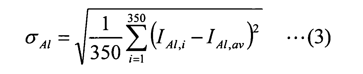
 in the formulae (2) to (4),i is a natural number of from 1 to 350,IAl,i is a characteristic X-ray intensity of aluminum that is measured by using an electron beam microanalyzer at the i-th intersection point among 350 intersection points of surfaces that are obtained by dividing the first catalyst layer into 350 equal parts in the thickness direction with a line that is vertical to the main surface of the first catalyst layer,IAl,av is an arithmetic average value of the IAl,i given by the following formula (5):
whereinIAE,i is a characteristic X-ray intensity of the alkaline-earth metal element that is measured by using the electron beam microanalyzer at the i-th intersection point, andIAE,av is an arithmetic average value of the IAE,i given by the following formula (6):
- The exhaust gas purification catalyst according to claim 1, wherein the correlation coefficient ρAl,AE is 0.79 or more.
- The exhaust gas purification catalyst according to claim 1 or 2, wherein the alkaline-earth metal element is barium.
- The exhaust gas purification catalyst according to any one of claims 1 to 3, wherein a content of the alkaline-earth metal element in the first catalyst layer per unit volume of the substrate is in the range of from 0.1 g/L to 80 g/L.
- The exhaust gas purification catalyst according to any one of claims 1 to 4, wherein the amount of the doped alkaline-earth metal element is in the range of from 0.1% by mass to 20% by mass based on mass of the alumina doped with the alkaline-earth metal element.
- The exhaust gas purification catalyst according to any one of claims 1 to 5, wherein mass ratio of a content of the alkaline-earth metal element with respect to a content of the palladium and/or platinum in the first catalyst layer is in the range of from 0.1 to 80.
- The exhaust gas purification catalyst according to any one of claims 1 to 6, further comprising a second catalyst layer formed on the first catalyst layer, the second catalyst layer comprising rhodium.
- The exhaust gas purification catalyst according to any one of claims 1 to 6, further comprising a second catalyst layer intervening between the substrate and the first catalyst layer, the second catalyst layer comprising rhodium.
- The exhaust gas purification catalyst according to claim 7 or 8, wherein the second catalyst layer is free from the alumina doped with the alkaline-earth metal element, or the second catalyst layer further comprises the alumina doped with the alkaline-earth metal element, and the content of the alkaline-earth metal element per unit volume of the substrate in the second catalyst layer is smaller than the content of the alkaline-earth metal element per unit volume of the substrate in the first catalyst layer.
- An exhaust gas purification catalyst comprising:a substrate, anda catalyst layer obtainable by applying a slurry comprising palladium and/or platinum and alumina doped with an alkaline-earth metal element onto the substrate.
Applications Claiming Priority (2)
| Application Number | Priority Date | Filing Date | Title |
|---|---|---|---|
| JP2008324265 | 2008-12-19 | ||
| PCT/JP2009/071172 WO2010071205A1 (en) | 2008-12-19 | 2009-12-18 | Catalyst for purification of exhaust gas |
Publications (2)
| Publication Number | Publication Date |
|---|---|
| EP2368630A1 true EP2368630A1 (en) | 2011-09-28 |
| EP2368630A4 EP2368630A4 (en) | 2013-07-31 |
Family
ID=42268872
Family Applications (1)
| Application Number | Title | Priority Date | Filing Date |
|---|---|---|---|
| EP09833507.8A Ceased EP2368630A4 (en) | 2008-12-19 | 2009-12-18 | CATALYST FOR THE PURIFICATION OF EXHAUST GASES |
Country Status (5)
| Country | Link |
|---|---|
| US (1) | US8318632B2 (en) |
| EP (1) | EP2368630A4 (en) |
| JP (1) | JP5323093B2 (en) |
| CN (1) | CN102256701B (en) |
| WO (1) | WO2010071205A1 (en) |
Cited By (8)
| Publication number | Priority date | Publication date | Assignee | Title |
|---|---|---|---|---|
| EP2444152A4 (en) * | 2009-06-16 | 2013-07-31 | Cataler Corp | EXHAUST GAS PURIFYING CATALYST, POWDER MATERIAL, AND PROCESS FOR PRODUCING EXHAUST PURIFYING CATALYST |
| EP2436441A4 (en) * | 2009-05-27 | 2013-07-31 | Cataler Corp | CATALYST FOR THE PURIFICATION OF EXHAUST GASES |
| WO2014135937A3 (en) * | 2013-03-05 | 2014-11-20 | Toyota Jidosha Kabushiki Kaisha | Diesel exhaust gas oxidation catalyst, and method for purifying diesel exhaust gas by using same |
| US9364793B2 (en) | 2009-05-27 | 2016-06-14 | Cataler Corporation | Exhaust gas-purifying catalyst |
| EP2457657A4 (en) * | 2009-07-24 | 2017-03-08 | Cataler Corporation | Exhaust gas purification catalyst |
| EP3072587A4 (en) * | 2013-11-22 | 2017-07-19 | Cataler Corporation | Catalyst for exhaust gas purification |
| EP3424592A4 (en) * | 2016-03-01 | 2019-11-27 | Cataler Corporation | DEVICE FOR PURIFYING EXHAUST GAS |
| US11446639B2 (en) | 2018-09-28 | 2022-09-20 | Umicore Shokubai Japan Co., Ltd. | Exhaust gas purification catalyst, exhaust gas purification method, and production method for exhaust gas purification catalyst |
Families Citing this family (16)
| Publication number | Priority date | Publication date | Assignee | Title |
|---|---|---|---|---|
| JP5938819B2 (en) | 2011-10-06 | 2016-06-22 | ジョンソン、マッセイ、パブリック、リミテッド、カンパニーJohnson Matthey Public Limited Company | Oxidation catalyst for exhaust gas treatment |
| GB201200781D0 (en) | 2011-12-12 | 2012-02-29 | Johnson Matthey Plc | Exhaust system for a lean-burn ic engine comprising a pgm component and a scr catalyst |
| GB201200784D0 (en) | 2011-12-12 | 2012-02-29 | Johnson Matthey Plc | Exhaust system for a lean-burn internal combustion engine including SCR catalyst |
| GB2497597A (en) | 2011-12-12 | 2013-06-19 | Johnson Matthey Plc | A Catalysed Substrate Monolith with Two Wash-Coats |
| GB201200783D0 (en) | 2011-12-12 | 2012-02-29 | Johnson Matthey Plc | Substrate monolith comprising SCR catalyst |
| JP5842656B2 (en) * | 2012-02-14 | 2016-01-13 | トヨタ自動車株式会社 | Method for producing exhaust gas purifying catalyst |
| JP5705785B2 (en) * | 2012-05-18 | 2015-04-22 | トヨタ自動車株式会社 | Exhaust gas purification catalyst |
| RU2573022C1 (en) * | 2012-04-27 | 2016-01-20 | Тойота Дзидося Кабусики Кайся | Ironoxide-zirconiumoxide mixed oxide, method of its obtaining and catalyst of exhaust gas purification |
| JP5690372B2 (en) * | 2012-04-27 | 2015-03-25 | 株式会社豊田中央研究所 | Iron oxide-zirconia composite oxide and method for producing the same |
| JP5705784B2 (en) * | 2012-05-18 | 2015-04-22 | トヨタ自動車株式会社 | Exhaust gas purification catalyst |
| JP6417333B2 (en) * | 2013-12-13 | 2018-11-07 | 株式会社キャタラー | Exhaust gas purification catalyst |
| JP6742751B2 (en) * | 2016-02-19 | 2020-08-19 | 株式会社キャタラー | Exhaust gas purification catalyst material and exhaust gas purification catalyst |
| JP6623111B2 (en) * | 2016-04-13 | 2019-12-18 | 株式会社キャタラー | Exhaust gas purification catalyst |
| EP3581269B1 (en) * | 2017-04-11 | 2022-09-28 | Cataler Corporation | Catalyst for exhaust gas purification and method of preparation |
| US20200030776A1 (en) * | 2018-07-27 | 2020-01-30 | Johnson Matthey Public Limited Company | Twc catalysts containing high dopant support |
| JP7195995B2 (en) | 2019-03-27 | 2022-12-26 | 株式会社キャタラー | Exhaust gas purification catalyst |
Family Cites Families (53)
| Publication number | Priority date | Publication date | Assignee | Title |
|---|---|---|---|---|
| US4128506A (en) * | 1978-01-23 | 1978-12-05 | General Motors Corporation | Platinum-rhodium catalyst for automotive emission control |
| US5597771A (en) * | 1993-06-25 | 1997-01-28 | Engelhard Corporation | Layered catalyst composite |
| DE69503527T2 (en) * | 1994-01-20 | 1999-04-29 | Toyota Jidosha K.K., Toyota, Aichi | Catalytic converter for cleaning exhaust gases |
| DE69412780T2 (en) * | 1994-01-28 | 1999-05-12 | Evangelos G. Patras Papadakis | Three-way catalyst with Pt, Rh and Pd, all with separate supports |
| JPH07289896A (en) * | 1994-04-26 | 1995-11-07 | Hitachi Ltd | Exhaust gas purifying catalyst and manufacturing method thereof |
| US5559073A (en) * | 1994-09-26 | 1996-09-24 | Beijing Huaxia Environmental Protection Company | Pollution control catalyst with mutual protective distributed-active-combinations each including noble-metal-atoms stably structured and protected therein |
| US5556825A (en) * | 1995-01-06 | 1996-09-17 | Ford Motor Company | Automotive catalysts with improved oxygen storage and metal dispersion |
| JP3799651B2 (en) * | 1995-04-28 | 2006-07-19 | マツダ株式会社 | Exhaust gas purification catalyst |
| JPH0910594A (en) * | 1995-04-28 | 1997-01-14 | Mazda Motor Corp | Exhaust gas purification catalyst |
| US5948723A (en) * | 1996-09-04 | 1999-09-07 | Engelhard Corporation | Layered catalyst composite |
| JPH10180099A (en) * | 1996-12-20 | 1998-07-07 | Ngk Insulators Ltd | Catalyst for purifying waste gas and waste gas purifying system |
| JPH10180041A (en) * | 1996-12-20 | 1998-07-07 | Ngk Insulators Ltd | Catalyst for purification of exhaust gas and exhaust gas purifying system |
| JP4092441B2 (en) * | 1997-02-24 | 2008-05-28 | 日産自動車株式会社 | Exhaust gas purification catalyst |
| GB9713428D0 (en) * | 1997-06-26 | 1997-08-27 | Johnson Matthey Plc | Improvements in emissions control |
| JP3827838B2 (en) | 1997-11-20 | 2006-09-27 | ダイハツ工業株式会社 | Exhaust gas purification catalyst |
| US6221804B1 (en) * | 1998-01-27 | 2001-04-24 | Mazda Motor Corporation | Catalyst for purifying exhaust gas and manufacturing method thereof |
| KR100326747B1 (en) * | 1998-03-09 | 2002-03-13 | 하나와 요시카즈 | Device for Purifying Oxygen Rich Exhaust Gas |
| GB9813367D0 (en) * | 1998-06-22 | 1998-08-19 | Johnson Matthey Plc | Catalyst |
| DE19847008A1 (en) * | 1998-10-13 | 2000-04-20 | Degussa | Nitrogen oxide storage catalytic converter |
| DE19854794A1 (en) * | 1998-11-27 | 2000-05-31 | Degussa | Catalyst for the purification of the exhaust gases of a diesel engine |
| JP2000176298A (en) * | 1998-12-11 | 2000-06-27 | Mazda Motor Corp | Exhaust gas purification catalyst and method for producing the same |
| DE60042991D1 (en) * | 1999-07-09 | 2009-11-05 | Nissan Motor | Exhaust gas purifying catalyst and process for its production |
| JP3756706B2 (en) * | 1999-09-03 | 2006-03-15 | ダイハツ工業株式会社 | Exhaust gas purification catalyst |
| US6391822B1 (en) * | 2000-02-09 | 2002-05-21 | Delphi Technologies, Inc. | Dual NOx adsorber catalyst system |
| GB0022786D0 (en) * | 2000-09-16 | 2000-11-01 | Johnson Matthey Plc | NOx-Trap composition |
| JP4573993B2 (en) * | 2000-11-09 | 2010-11-04 | 日産自動車株式会社 | Exhaust gas purification catalyst and method for producing the same |
| GB0028240D0 (en) * | 2000-11-20 | 2001-01-03 | Johnson Matthey Plc | Three-way catalyst composition |
| KR100492644B1 (en) * | 2001-02-26 | 2005-06-02 | 미쓰비시 지도샤 고교(주) | Catalyst for exhaust gas purification |
| US6777370B2 (en) * | 2001-04-13 | 2004-08-17 | Engelhard Corporation | SOx tolerant NOx trap catalysts and methods of making and using the same |
| US6764665B2 (en) * | 2001-10-26 | 2004-07-20 | Engelhard Corporation | Layered catalyst composite |
| EP1316354A1 (en) * | 2001-11-30 | 2003-06-04 | OMG AG & Co. KG | Catalyst for the reduction of nitrogen oxides in exhaust gas of lean burn engines |
| US7071141B2 (en) * | 2002-10-24 | 2006-07-04 | Ford Global Technologies, Llc | Perovskite catalyst system for lean burn engines |
| US7329629B2 (en) * | 2002-10-24 | 2008-02-12 | Ford Global Technologies, Llc | Catalyst system for lean burn engines |
| US7022646B2 (en) * | 2003-01-31 | 2006-04-04 | Engelhard Corporation | Layered catalyst composite |
| US7385889B2 (en) * | 2003-03-03 | 2008-06-10 | Samsung Electronics Co., Ltd. | Method and apparatus for managing disc defect using temporary DFL and temporary DDS including drive and disc information disc with temporary DFL and temporary DDS |
| JP4460844B2 (en) * | 2003-04-17 | 2010-05-12 | 株式会社アイシーティー | Exhaust gas purification catalyst and exhaust gas purification method |
| DE10335785A1 (en) * | 2003-08-05 | 2005-03-10 | Umicore Ag & Co Kg | Catalyst arrangement and method for purifying the exhaust gas of lean burn internal combustion engines |
| US7875250B2 (en) * | 2003-12-11 | 2011-01-25 | Umicore Ag & Co. Kg | Exhaust treatment device, and methods of making the same |
| US7374729B2 (en) * | 2004-03-30 | 2008-05-20 | Basf Catalysts Llc | Exhaust gas treatment catalyst |
| CN1938089B (en) * | 2004-03-30 | 2010-12-08 | 日挥通用株式会社 | Catalyst for purifying exhaust gas and method for purifying exhaust gas |
| US7737077B2 (en) * | 2004-11-25 | 2010-06-15 | Cataler Corporation | Catalyst for purifying exhaust gases |
| KR101051418B1 (en) * | 2006-03-16 | 2011-07-22 | 인터내쇼날 카탈리스트 테크놀로지, 인코포레이티드 | Catalyst for purification of exhaust gas, method for producing same and method for purification of exhaust gas using such catalyst |
| US7749472B2 (en) * | 2006-08-14 | 2010-07-06 | Basf Corporation | Phosgard, a new way to improve poison resistance in three-way catalyst applications |
| US7550124B2 (en) * | 2006-08-21 | 2009-06-23 | Basf Catalysts Llc | Layered catalyst composite |
| US7517510B2 (en) * | 2006-08-21 | 2009-04-14 | Basf Catalysts Llc | Layered catalyst composite |
| EP1952876A1 (en) * | 2007-01-25 | 2008-08-06 | Nissan Motor Co., Ltd. | Exhaust gas purifying catalyst and manufacturing method thereof |
| US7754171B2 (en) * | 2007-02-02 | 2010-07-13 | Basf Corporation | Multilayered catalyst compositions |
| JP5232401B2 (en) * | 2007-04-05 | 2013-07-10 | 株式会社キャタラー | Exhaust gas purification catalyst |
| US8007750B2 (en) * | 2007-07-19 | 2011-08-30 | Basf Corporation | Multilayered catalyst compositions |
| US7879755B2 (en) * | 2007-08-09 | 2011-02-01 | Basf Corporation | Catalyst compositions |
| JP5337876B2 (en) * | 2009-05-27 | 2013-11-06 | 株式会社キャタラー | Exhaust gas purification catalyst and method for producing the same |
| WO2010137657A1 (en) * | 2009-05-27 | 2010-12-02 | 株式会社 キャタラー | Catalyst for purification of exhaust gas |
| EP2444152A4 (en) * | 2009-06-16 | 2013-07-31 | Cataler Corp | EXHAUST GAS PURIFYING CATALYST, POWDER MATERIAL, AND PROCESS FOR PRODUCING EXHAUST PURIFYING CATALYST |
-
2009
- 2009-12-18 JP JP2010543017A patent/JP5323093B2/en not_active Expired - Fee Related
- 2009-12-18 CN CN200980150857.9A patent/CN102256701B/en not_active Expired - Fee Related
- 2009-12-18 WO PCT/JP2009/071172 patent/WO2010071205A1/en not_active Ceased
- 2009-12-18 EP EP09833507.8A patent/EP2368630A4/en not_active Ceased
-
2011
- 2011-06-17 US US13/163,341 patent/US8318632B2/en not_active Expired - Fee Related
Cited By (11)
| Publication number | Priority date | Publication date | Assignee | Title |
|---|---|---|---|---|
| EP2436441A4 (en) * | 2009-05-27 | 2013-07-31 | Cataler Corp | CATALYST FOR THE PURIFICATION OF EXHAUST GASES |
| US8580706B2 (en) | 2009-05-27 | 2013-11-12 | Cataler Corporation | Exhaust gas-purifying catalyst |
| US9364793B2 (en) | 2009-05-27 | 2016-06-14 | Cataler Corporation | Exhaust gas-purifying catalyst |
| EP2444152A4 (en) * | 2009-06-16 | 2013-07-31 | Cataler Corp | EXHAUST GAS PURIFYING CATALYST, POWDER MATERIAL, AND PROCESS FOR PRODUCING EXHAUST PURIFYING CATALYST |
| US8546296B2 (en) | 2009-06-16 | 2013-10-01 | Cataler Corporation | Exhaust gas-purifying catalyst, powdery material, and method of manufacturing exhaust gas-purifying catalyst |
| EP2457657A4 (en) * | 2009-07-24 | 2017-03-08 | Cataler Corporation | Exhaust gas purification catalyst |
| WO2014135937A3 (en) * | 2013-03-05 | 2014-11-20 | Toyota Jidosha Kabushiki Kaisha | Diesel exhaust gas oxidation catalyst, and method for purifying diesel exhaust gas by using same |
| EP3072587A4 (en) * | 2013-11-22 | 2017-07-19 | Cataler Corporation | Catalyst for exhaust gas purification |
| EP3424592A4 (en) * | 2016-03-01 | 2019-11-27 | Cataler Corporation | DEVICE FOR PURIFYING EXHAUST GAS |
| US10710023B2 (en) | 2016-03-01 | 2020-07-14 | Cataler Corporation | Exhaust gas purification catalyst |
| US11446639B2 (en) | 2018-09-28 | 2022-09-20 | Umicore Shokubai Japan Co., Ltd. | Exhaust gas purification catalyst, exhaust gas purification method, and production method for exhaust gas purification catalyst |
Also Published As
| Publication number | Publication date |
|---|---|
| US20110245076A1 (en) | 2011-10-06 |
| JP5323093B2 (en) | 2013-10-23 |
| US8318632B2 (en) | 2012-11-27 |
| CN102256701B (en) | 2014-04-09 |
| CN102256701A (en) | 2011-11-23 |
| EP2368630A4 (en) | 2013-07-31 |
| JPWO2010071205A1 (en) | 2012-05-31 |
| WO2010071205A1 (en) | 2010-06-24 |
Similar Documents
| Publication | Publication Date | Title |
|---|---|---|
| EP2368630A1 (en) | Exhaust gas purification catalyst | |
| EP2436441B1 (en) | Exhaust gas-purifying catalyst | |
| KR101432330B1 (en) | Exhaust gas-purifying catalyst | |
| CN102802784B (en) | Exhaust gas purifying catalyst, powder material, and method for producing exhaust gas purifying catalyst | |
| KR101520983B1 (en) | Catalyst compositions | |
| EP1339490B1 (en) | Manganese containing oxygen storage component comprising three-way catalyst composition | |
| US10753248B2 (en) | Exhaust gas purification catalyst | |
| CN102448608B (en) | Catalyst for purifying exhaust gas and manufacturing method thereof | |
| KR101155847B1 (en) | Exhaust gas purifying catalyst | |
| US20140221198A1 (en) | Catalyst carrier for exhaust gas purification and catalyst for exhaust gas purification | |
| EP2078562B1 (en) | Exhaust gas purifying catalyst | |
| US9415383B2 (en) | Exhaust gas purification catalyst | |
| EP2301662A1 (en) | Exhaust gas purification catalyst | |
| JP6339013B2 (en) | Exhaust gas purification catalyst carrier, exhaust gas purification catalyst, and exhaust gas purification catalyst structure | |
| US20160082420A1 (en) | Catalyst system for exhaust gas purification and method for exhaust gas purification | |
| US8932982B2 (en) | Exhaust gas purification catalyst | |
| JP2010227799A (en) | Exhaust gas purification catalyst | |
| US20260070043A1 (en) | Exhaust gas purification catalyst | |
| JP2005000884A (en) | Exhaust gas purification catalyst | |
| JP2026049572A (en) | Exhaust gas purification catalyst | |
| JPH06205975A (en) | Exhaust gas purification catalyst | |
| KR20030091347A (en) | Method for manufacturing low precious metal loading Pd only three way catalyst |
Legal Events
| Date | Code | Title | Description |
|---|---|---|---|
| PUAI | Public reference made under article 153(3) epc to a published international application that has entered the european phase |
Free format text: ORIGINAL CODE: 0009012 |
|
| 17P | Request for examination filed |
Effective date: 20110617 |
|
| AK | Designated contracting states |
Kind code of ref document: A1 Designated state(s): AT BE BG CH CY CZ DE DK EE ES FI FR GB GR HR HU IE IS IT LI LT LU LV MC MK MT NL NO PL PT RO SE SI SK SM TR |
|
| DAX | Request for extension of the european patent (deleted) | ||
| A4 | Supplementary search report drawn up and despatched |
Effective date: 20130702 |
|
| RIC1 | Information provided on ipc code assigned before grant |
Ipc: B01D 53/94 20060101ALI20130626BHEP Ipc: B01J 37/02 20060101ALI20130626BHEP Ipc: F01N 3/10 20060101ALI20130626BHEP Ipc: B01J 23/58 20060101AFI20130626BHEP |
|
| 17Q | First examination report despatched |
Effective date: 20160223 |
|
| REG | Reference to a national code |
Ref country code: DE Ref legal event code: R003 |
|
| STAA | Information on the status of an ep patent application or granted ep patent |
Free format text: STATUS: THE APPLICATION HAS BEEN REFUSED |
|
| 18R | Application refused |
Effective date: 20170506 |