EP2368614A1 - Toy motorcycle for tracks with a guide groove - Google Patents
Toy motorcycle for tracks with a guide groove Download PDFInfo
- Publication number
- EP2368614A1 EP2368614A1 EP08875590A EP08875590A EP2368614A1 EP 2368614 A1 EP2368614 A1 EP 2368614A1 EP 08875590 A EP08875590 A EP 08875590A EP 08875590 A EP08875590 A EP 08875590A EP 2368614 A1 EP2368614 A1 EP 2368614A1
- Authority
- EP
- European Patent Office
- Prior art keywords
- motorcycle
- track
- frame
- rack
- wheel
- Prior art date
- Legal status (The legal status is an assumption and is not a legal conclusion. Google has not performed a legal analysis and makes no representation as to the accuracy of the status listed.)
- Granted
Links
- 230000000694 effects Effects 0.000 description 3
- 230000005484 gravity Effects 0.000 description 3
- 230000000670 limiting effect Effects 0.000 description 2
- 239000000725 suspension Substances 0.000 description 2
- 241000826860 Trapezium Species 0.000 description 1
- 230000006978 adaptation Effects 0.000 description 1
- 238000004519 manufacturing process Methods 0.000 description 1
- 239000000463 material Substances 0.000 description 1
- 238000011084 recovery Methods 0.000 description 1
- 238000004088 simulation Methods 0.000 description 1
- 230000003019 stabilising effect Effects 0.000 description 1
Images


Classifications
-
- A—HUMAN NECESSITIES
- A63—SPORTS; GAMES; AMUSEMENTS
- A63H—TOYS, e.g. TOPS, DOLLS, HOOPS OR BUILDING BLOCKS
- A63H17/00—Toy vehicles, e.g. with self-drive; ; Cranes, winches or the like; Accessories therefor
- A63H17/21—Toy vehicles, e.g. with self-drive; ; Cranes, winches or the like; Accessories therefor shaped as motorcycles with or without figures
-
- A—HUMAN NECESSITIES
- A63—SPORTS; GAMES; AMUSEMENTS
- A63H—TOYS, e.g. TOPS, DOLLS, HOOPS OR BUILDING BLOCKS
- A63H18/00—Highways or trackways for toys; Propulsion by special interaction between vehicle and track
- A63H18/16—Control of vehicle drives by interaction between vehicle and track; Control of track elements by vehicles
- A63H2018/165—Means to improve adhesion of the vehicles on the track, e.g. using magnetic forces
Definitions
- Toy motorcycle for tracks with guiding groove of the type comprising an electric motor, a motorcycle chassis, a guide, arranged inside the guiding groove of a track, joined to a structure, located at the bottom of the motorcycle, with at least two support wheels and a magnet, which comprises a frame connected to the chassis, a rear traction wheel, upon which the electric motor acts, integral with the frame, and a tilting system for tilting the frame along the track curve, with respect to the structure, moving a rear wheel, with said wheel defining a curve trajectory different to the curve trajectory of the guide.
- Spanish Utility Model No. 9400257 ( ES1026976 ) from 1994, is known, in the name of Mr. Juan Manuel G ⁇ MEZ SALCEDO, which relates to a motor vehicle support with an incorporated motorcycle provided with all types of movement, applicable to electric tracks, characterised in that it is shaped from a base plate, made from an appropriate material, which adopts a noticeably elongated shape, provided with side wings in the middle rear area, where wheels are coupled to stabilise the unit, in which base plate on the inner face thereof a strip of appropriate length is hinged, which is flat and has a rotation axis at is rear end, which coincides with the middle rear area of the base plate, said strip having hinged at its front end, a guide piece that fits between the rails of the electric track in question, while the middle rear area has a vertical axis that crosses the base plate through an arched groove, which has an axis at its top end with a yoke in which there fits an integral bolt of a connecting rod arranged parallel to said axi
- This invention is an improvement in the sector of motorcycles for slot tracks.
- the inventions try to solve the problem of how to simulate the effect of the motorcycle tilting in very different ways.
- the inventor with the idea of making it as realistic as possible, has developed a mechanism which, when the motorcycle reaches a curve, allows it to tilt gradually as the curve becomes more pronounced, and as the curve opens up, it recovers its vertical position.
- the inventor avails of the centrifugal force produced as the motorcycle rotates in the curve, which sends said motorcycle outwards, so that the wheels come out of the trajectory of the guiding groove, skidding, in turn tilting the motorcycle via the action of the force of gravity that compensates the centrifugal force.
- the centrifugal force on the motorcycle reduces and the motorcycle recovers its initial position owing to the compensation of forces between the centrifugal force and gravitational force.
- An object of this invention is a toy motorcycle for tracks with a guiding groove of the type comprising an electric motor, a motorcycle chassis, a guide, arranged inside a guiding groove of a track, joint to a structure, located in the bottom part of the motorcycle, with at least two support wheels and a magnet, characterised in that it has a frame associated with the chassis, a rear traction wheel, on which the electric motor acts, which is integral with the frame, and a tilting system for tilting the frame along the track curve, with respect to the structure, moving a rear wheel, with said wheel defining a curve trajectory that is different to the curve trajectory of the guide.
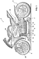
- Figure 1 shows a track 1, a motorcycle 3, with its chassis 10, a front wheel 5, a rear wheel 6, an electric motor 12, a structure 16, support wheels 7, a guide 4, braids 14, strips 11 which confine a first rack 8, a toothed wheel 13 and a second rack 9, a yoke 22 and a spring 20.
- Figure 2 shows track 1, with the guiding groove 2, front wheel 5 and rear wheel 6, electric motor 12, a steering rotor 21, a yoke 22, structure 16, support wheels 7, a magnet 23, strips 11 with first rack 8, second rack 9, toothed wheel 13 and a frame 15 with spring 20.
- Figure 3 shows said track 1, with guiding groove 2, front wheel 5 and rear wheel 6, structure 16, support wheels 7, strips 11 with second rack 9, toothed wheel 13, electric motor 12, steering rotor 21, yoke 22 and frame 15 with spring 20.
- Figure 4 shows guide 4, braids 14, the structure divided into two parts 16a and 16b, support wheels 7, steering rotor 21, strip 11, first rack 8 with first rotation axis 18, second rack 9 with second rotation axis 19, toothed wheel 13 and frame 15.
- motorcycle 3 is arranged on track 1 ( Figure 1 ) introducing the guide 4 into guiding groove 2 (see Figs 2 and 3 ). So, braids 14 come into contact with guiding groove 2 and the electric current supplies electric motor 12 of motorcycle 3, which acts upon rear wheel 6.
- the toy motorcycle for tracks with a guiding groove comprises electric motor 12, chassis 10 of motorcycle 3, guide 4, arranged inside a guiding groove 2 of track 1, joined to a structure 16, located at the bottom of motorcycle 3, with at least two support wheels 7 and a magnet 23.
- It also comprises frame 15 associated to chassis 10, rear traction wheel 6, on which electric motor 12 acts, integral with frame 15, and a tilting system for tilting frame 15 along the curve of track 1, with respect to structure 16, moving rear wheel 6, with said rear wheel 6 defining a curve trajectory that is different to the curve trajectory of guide 4 (see Figs. 2 and 3 ).
- the tilting system be a system of racks, although others could be considered, such as for example, a cam-based system.
- This tilting movement is achieved via a first rack 8, integral to guide 4.
- first rack 8 integral to guide 4.
- toothed wheel 13 which moves on first rack 8
- chassis 3 which is integral to frame 15 that is joined to second rack 9 also tilts and simulates the same tilting effect of top competition motorcycles. Even so, it is important to take into account the function of strips 11, as will be detailed below, which will show that the movement is produced by the rotation of second rack 9 on toothed wheel 13, which respectively rotates first rack 8.
- support wheels 7 that are integral to structure 16 maintain the same trajectory as guide 4 and always remain adhered to track 1. This is also determined by the existence of magnet 23, located at the bottom of structure 16, which increases the adherence of structure 16 to track 1.
- toothed wheel 13 would rotate in the opposite direction on first 8 and second 9 racks, leaving said racks 8, 9 and toothed wheel 13 perpendiculars to track 1.
- Strips 11 have a double function. On the one hand they support said racks 8, 9 and toothed wheel 13, and on the other hand, they allow the above-mentioned tilting action of motorcycle 3.
- first rotation axis 18 allows strips 11 to rotate from a fixed point, such as the first rack 8, producing the tilting movement, and at the same time second rack 9 can rotation according to the tilting angle of strips 11, and therewith toothed wheel 13.
- frame 15 tilts which does the same to the motorcycle chassis 10.
- Figure 4 shows in detail mainly racks 8, 9, their link to structure 16 and frame 15 respectively and their relation with guide 4.
- steering rotor 21 is extended imaginary towards track 1, the point of intersection between both is the point at which front wheel 5 comes into contact with track 1, and not as would be logical, the extension of yoke 22. In other words, the extension axis of steering rotor 21 is different from that of yoke 22.
- front wheel 5 helps the motorcycle unit to move outside of the trajectory of guide 4.
- front wheel 5 changes completely, since when tilted the point of support of front wheel 5 on track 1 varies with respect to the rotation axis of the steering yoke 22. So, front wheel 5 tends to help centre motorcycle 3 towards said guiding groove 2.
- structure 16 can, for manufacturing reasons, be made in one or several parts, and in this embodiment it is in two parts 16a and 16b, which are joined to form a whole.
Landscapes
- Toys (AREA)
Abstract
Description
- Toy motorcycle for tracks with guiding groove of the type comprising an electric motor, a motorcycle chassis, a guide, arranged inside the guiding groove of a track, joined to a structure, located at the bottom of the motorcycle, with at least two support wheels and a magnet, which comprises a frame connected to the chassis, a rear traction wheel, upon which the electric motor acts, integral with the frame, and a tilting system for tilting the frame along the track curve, with respect to the structure, moving a rear wheel, with said wheel defining a curve trajectory different to the curve trajectory of the guide.
- Spanish Patent No.
9300204 ES2067384 - Also Spanish Utility Model No.
9400257 ES1026976 - The closest document found is Spanish Patent No.
200800276 ES2303494 - This invention is an improvement in the sector of motorcycles for slot tracks.
- As can be verified by the background to the invention, the inventions try to solve the problem of how to simulate the effect of the motorcycle tilting in very different ways.
- There are inventions (U9400257) (
ES1026976 - Others (P9300204) (
ES2067384 - Lastly, a third group (P200800276) (
ES2303494 - The inventor, with the idea of making it as realistic as possible, has developed a mechanism which, when the motorcycle reaches a curve, allows it to tilt gradually as the curve becomes more pronounced, and as the curve opens up, it recovers its vertical position.
- So, the inventor avails of the centrifugal force produced as the motorcycle rotates in the curve, which sends said motorcycle outwards, so that the wheels come out of the trajectory of the guiding groove, skidding, in turn tilting the motorcycle via the action of the force of gravity that compensates the centrifugal force.
- Continuing the trajectory and facing the next straight section, the centrifugal force on the motorcycle reduces and the motorcycle recovers its initial position owing to the compensation of forces between the centrifugal force and gravitational force.
- An object of this invention is a toy motorcycle for tracks with a guiding groove of the type comprising an electric motor, a motorcycle chassis, a guide, arranged inside a guiding groove of a track, joint to a structure, located in the bottom part of the motorcycle, with at least two support wheels and a magnet, characterised in that it has a frame associated with the chassis, a rear traction wheel, on which the electric motor acts, which is integral with the frame, and a tilting system for tilting the frame along the track curve, with respect to the structure, moving a rear wheel, with said wheel defining a curve trajectory that is different to the curve trajectory of the guide.
- In order to facilitate the explanation four sheets of drawings are attached to this invention, which represent a practical embodiment, which is provided as a non-limiting example of the scope of this invention:
-
Figure 1 is a side view of the aim of this invention; -
Figure 2 is an elevate left side view from behind of the motorcycle, in a curve and without the chassis; -
Figure 3 is a view of a right side view of the motorcycle, and -
Figure 4 is a detailed view of the central part of the motorcycle. - So
Figure 1 shows atrack 1, amotorcycle 3, with itschassis 10, afront wheel 5, arear wheel 6, anelectric motor 12, astructure 16,support wheels 7, aguide 4,braids 14,strips 11 which confine afirst rack 8, atoothed wheel 13 and asecond rack 9, ayoke 22 and aspring 20. -
Figure 2 showstrack 1, with the guiding groove 2,front wheel 5 andrear wheel 6,electric motor 12, asteering rotor 21, ayoke 22,structure 16,support wheels 7, amagnet 23,strips 11 withfirst rack 8,second rack 9,toothed wheel 13 and aframe 15 withspring 20. -
Figure 3 shows saidtrack 1, with guiding groove 2,front wheel 5 andrear wheel 6,structure 16,support wheels 7,strips 11 withsecond rack 9,toothed wheel 13,electric motor 12,steering rotor 21,yoke 22 andframe 15 withspring 20. - Lastly,
Figure 4 showsguide 4,braids 14, the structure divided into twoparts support wheels 7,steering rotor 21,strip 11,first rack 8 withfirst rotation axis 18,second rack 9 withsecond rotation axis 19,toothed wheel 13 andframe 15. - This way, in a particular embodiment,
motorcycle 3 is arranged on track 1 (Figure 1 ) introducing theguide 4 into guiding groove 2 (seeFigs 2 and3 ). So,braids 14 come into contact with guiding groove 2 and the electric current supplieselectric motor 12 ofmotorcycle 3, which acts uponrear wheel 6. - In
Figure 1 , in the interest of clarity, a simulation has been produced whereinmotorcycle 3 has been raised at the front part thereof to provide a better view ofbraids 14,support wheels 7 andguide 4. Therefore, neithersupport wheels 7 norbraids 14 are, in this view, in contact withtrack 1 or guidinggroove 4. - Essentially, the toy motorcycle for tracks with a guiding groove comprises
electric motor 12,chassis 10 ofmotorcycle 3,guide 4, arranged inside a guiding groove 2 oftrack 1, joined to astructure 16, located at the bottom ofmotorcycle 3, with at least twosupport wheels 7 and amagnet 23. - It also comprises
frame 15 associated tochassis 10,rear traction wheel 6, on whichelectric motor 12 acts, integral withframe 15, and a tilting system for tiltingframe 15 along the curve oftrack 1, with respect tostructure 16, movingrear wheel 6, with saidrear wheel 6 defining a curve trajectory that is different to the curve trajectory of guide 4 (seeFigs. 2 and3 ). - In this embodiment it has been chosen that the tilting system be a system of racks, although others could be considered, such as for example, a cam-based system.
- Upon reaching the curve (see
Figs. 2 and3 ), as a result of thecentrifugal force motorcycle 3 tends to come out of guiding groove 2. - This way, owing to the action of said
centrifugal force chassis 10 tilts, as gravity balances said centrifugal force and positions the wheels outside the trajectory of guiding groove 2, imitating the action of competition motorcycles in speed races. - This tilting movement is achieved via a
first rack 8, integral toguide 4. When the curve beginssecond rack 9 is moved and movestoothed wheel 13 which moves onfirst rack 8, wherebychassis 3, which is integral toframe 15 that is joined tosecond rack 9 also tilts and simulates the same tilting effect of top competition motorcycles. Even so, it is important to take into account the function ofstrips 11, as will be detailed below, which will show that the movement is produced by the rotation ofsecond rack 9 ontoothed wheel 13, which respectively rotatesfirst rack 8. - To maintain adherence, support
wheels 7 that are integral tostructure 16 maintain the same trajectory asguide 4 and always remain adhered to track 1. This is also determined by the existence ofmagnet 23, located at the bottom ofstructure 16, which increases the adherence ofstructure 16 to track 1. - Once
motorcycle 3 recovers its straight trajectory, the centrifugal force tends to disappear and somotorcycle 3 recovers its vertical position via the action of gravity which in compensating the centrifugal force returnsmotorcycle 3 to its more stable position. - In other words,
toothed wheel 13 would rotate in the opposite direction on first 8 and second 9 racks, leaving saidracks toothed wheel 13 perpendiculars to track 1. -
Strips 11 have a double function. On the one hand they support said racks 8, 9 andtoothed wheel 13, and on the other hand, they allow the above-mentioned tilting action ofmotorcycle 3. - Said tilting movement is maintained when the
first rotation axis 18 allowsstrips 11 to rotate from a fixed point, such as thefirst rack 8, producing the tilting movement, and at the same timesecond rack 9 can rotation according to the tilting angle ofstrips 11, and therewithtoothed wheel 13. Whensecond rack 9 rotates inturn frame 15 tilts which does the same to themotorcycle chassis 10. -
Figure 4 shows in detail mainly racks 8, 9, their link tostructure 16 andframe 15 respectively and their relation withguide 4. - To increase the motorcycle's adherence to track 1 and facilitate recovery, if
steering rotor 21 is extended imaginary towardstrack 1, the point of intersection between both is the point at whichfront wheel 5 comes into contact withtrack 1, and not as would be logical, the extension ofyoke 22. In other words, the extension axis ofsteering rotor 21 is different from that ofyoke 22. - Thanks to the rotation geometry of
yoke 22 since the extension axis ofrotor 21 and ofyoke 22 are offset it is possible to improve the fact that when themotorcycle 3 is in a vertical positionfront wheel 5 tends to separate the trajectory of the motorcycle towards either side. - When the centrifugal force acts,
front wheel 5 helps the motorcycle unit to move outside of the trajectory ofguide 4. - Once
motorcycle 3 is tilted, the function offront wheel 5 changes completely, since when tilted the point of support offront wheel 5 ontrack 1 varies with respect to the rotation axis of thesteering yoke 22. So,front wheel 5 tends to help centremotorcycle 3 towards said guiding groove 2. - So when there is no more centrifugal force,
motorcycle 3 returns to its vertical position more quickly. - The result is that we have a
motorcycle 3 that is permanently unstable. So with this rotation geometry, when the centrifugal force acts, it quickly moves towards the outside of the curve and vice versa. - As can be seen,
structure 16 can, for manufacturing reasons, be made in one or several parts, and in this embodiment it is in twoparts - As can be seen in
Figure 1 it is envisaged to provide aspring 20, betweenframe 15 andelectric motor 12, to give themotorcycle 3 greater stability in the curves. In principlefront wheel 5 tends to open up or move outwards, which is partially compensated by saidspring 20. - To summarise, with this tilting system based on tilting
frame 15, the motorcycle is not free, instead it follows the path defined byguide 4 without any problems. - This patent of invention describes a new toy motorcycle for tracks with a guiding groove. The examples mentioned herein have a non-limiting effect on this invention, and therefore this invention can have different applications and/or adaptation, all within the scope of the following claims.
Claims (6)
- Toy motorcycle for tracks with a guiding groove of the type comprising an electric motor (12), a chassis (10) of motorcycle (3), a guide (4), arranged inside a guiding groove (2) of a track (1), joined to a structure (16), located at the bottom of motorcycle (3), with at least two support wheels (7) and a magnet (23), characterised in that it comprises- a frame (15) associated with chassis (10),- a rear traction wheel (6), on which electric motor (12) acts, integral with frame (15), and- a tilting system that tilts frame (15) in the curve of track (1), with respect to structure (16), moving rear wheel (6), with said rear wheel (6) defining a different curve trajectory to the curve trajectory of guide (4).
- Motorcycle according to claim 1, characterised in that the tilting system based on tilting frame (15) in the curve of track (1) comprises:- a first rack (8), integral with guide (4),- at least one toothed wheel (13), which meshes in said first rack (8),- a second rack (9) that meshes in toothed wheel (13) and is integral with frame (15),- a pair of strips (11) that confine first (8) and second (9) racks and toothed wheel (13), and- two rotation axes that join both strips (11), a first one (18) crossing through first rack (8) and a second one (19) crossing second rack (9).
- Motorcycle according to claim 1 or 2, characterised in that it comprises a steering rotor (21) and a yoke (22) to which front wheel (5) is attached, and in that if said steering rotor (21) is extended imaginary towards track (1) the point of intersection between both is the point at which front wheel (5) comes into contact with track (1).
- Motorcycle according to claim 3, characterised in that when wheels (5, 6) are outside the trajectory of guiding groove (2), chassis (10) is tilted with respect to the plan of track (1) and support wheels (7) and at least rear wheel (6) are on track (1).
- Motorcycle according to claim 4, characterised in that it comprises a spring (20) between frame (15) and electric motor (12).
- Motorcycle according to claim 1 or 2, characterised in that structure (16) comprises at least two parts (16a, 16b) joined together.
Applications Claiming Priority (1)
| Application Number | Priority Date | Filing Date | Title |
|---|---|---|---|
| PCT/ES2008/070207 WO2010058040A1 (en) | 2008-11-18 | 2008-11-18 | Toy motorcycle for tracks with a guide groove |
Publications (2)
| Publication Number | Publication Date |
|---|---|
| EP2368614A1 true EP2368614A1 (en) | 2011-09-28 |
| EP2368614B1 EP2368614B1 (en) | 2013-06-05 |
Family
ID=40973536
Family Applications (1)
| Application Number | Title | Priority Date | Filing Date |
|---|---|---|---|
| EP08875590.5A Not-in-force EP2368614B1 (en) | 2008-11-18 | 2008-11-18 | Toy motorcycle for tracks with a guide groove |
Country Status (5)
| Country | Link |
|---|---|
| US (1) | US8758079B2 (en) |
| EP (1) | EP2368614B1 (en) |
| CN (1) | CN102215925B (en) |
| ES (1) | ES2420975T3 (en) |
| WO (1) | WO2010058040A1 (en) |
Families Citing this family (6)
| Publication number | Priority date | Publication date | Assignee | Title |
|---|---|---|---|---|
| ES2303494B1 (en) * | 2008-02-01 | 2009-08-06 | Bycmo Rc Models, S.L | SLOT MOTORCYCLE. |
| US20130040533A1 (en) * | 2011-08-12 | 2013-02-14 | Andrew Kevin Miller | Miniature vehicle and set |
| CN106975227A (en) * | 2016-01-19 | 2017-07-25 | 广东佳奇科技教育股份有限公司 | A kind of variable body Dinosaur toy tank |
| CN106110668B (en) * | 2016-08-26 | 2019-01-01 | 济南爱动动漫科技有限公司 | The fall arrest accessory of guiding is provided for the walking of motorcycle |
| CN106110671B (en) * | 2016-08-26 | 2019-01-01 | 济南爱动动漫科技有限公司 | The toy fittings for preventing motorcycle from overturning |
| US10688404B2 (en) | 2017-02-15 | 2020-06-23 | Mattel, Inc. | Remotely controlled toy vehicle |
Family Cites Families (15)
| Publication number | Priority date | Publication date | Assignee | Title |
|---|---|---|---|---|
| US3785086A (en) * | 1973-01-02 | 1974-01-15 | F Escobedo | Self-steering bicycle-type toy vehicle |
| US4290228A (en) * | 1980-02-13 | 1981-09-22 | Adolph E. Goldfarb | Toy vehicles with automatic banking |
| FR2486809A1 (en) * | 1980-07-17 | 1982-01-22 | Marcus Michel | Electrically operated toy motor-bike and track - use support strut for balancing weight fitting through guide slot along centre of track to provide tilting effect during cornering |
| ES2067384B1 (en) | 1993-02-04 | 1998-08-01 | Pablos Baeza Carlos Jesus De | MOTORCYCLE FOR ELECTRIC TRACKS. |
| ES1026976Y (en) | 1994-02-01 | 1995-02-16 | Salcedo Juan Manuel Gomez | MOTOR VEHICLE SUPPORT WITH BUILT-IN MOTORCYCLE WITH ALL KINDS OF MOVEMENTS, APPLICABLE ON ELECTRIC TRACKS. |
| US6095891A (en) * | 1998-11-18 | 2000-08-01 | Bang Zoom Design, Ltd. | Remote control toy vehicle with improved stability |
| JP3059588U (en) * | 1998-12-02 | 1999-07-09 | 株式会社トミー | Track device |
| US6095892A (en) * | 1998-12-17 | 2000-08-01 | Moe; Courtney A. | Motorcycle race track with moving rider figurines |
| US6626116B2 (en) * | 2000-01-07 | 2003-09-30 | Leonard R. Clark, Jr. | Outlaw powersliders toy racing vehicles |
| US6524158B1 (en) * | 2000-04-18 | 2003-02-25 | Peter Sui Lun Fong | Animated toy |
| WO2004056436A1 (en) * | 2002-12-20 | 2004-07-08 | Nikko Co., Ltd. | Radio-controlled motorcycle toy |
| EP1550491A1 (en) * | 2003-12-31 | 2005-07-06 | Design Circle Inc. | Improved toy track and toy vehicle |
| JP4336355B2 (en) * | 2006-07-04 | 2009-09-30 | 株式会社ウィズ | Two-wheeled toy |
| US7601068B1 (en) * | 2007-01-24 | 2009-10-13 | Mcgee Lewis A | Car racing system |
| ES2303494B1 (en) | 2008-02-01 | 2009-08-06 | Bycmo Rc Models, S.L | SLOT MOTORCYCLE. |
-
2008
- 2008-11-18 CN CN200880132002.9A patent/CN102215925B/en not_active Expired - Fee Related
- 2008-11-18 EP EP08875590.5A patent/EP2368614B1/en not_active Not-in-force
- 2008-11-18 US US13/129,466 patent/US8758079B2/en not_active Expired - Fee Related
- 2008-11-18 ES ES08875590T patent/ES2420975T3/en active Active
- 2008-11-18 WO PCT/ES2008/070207 patent/WO2010058040A1/en not_active Ceased
Non-Patent Citations (1)
| Title |
|---|
| See references of WO2010058040A1 * |
Also Published As
| Publication number | Publication date |
|---|---|
| ES2420975T3 (en) | 2013-08-28 |
| CN102215925A (en) | 2011-10-12 |
| CN102215925B (en) | 2013-06-19 |
| US8758079B2 (en) | 2014-06-24 |
| WO2010058040A1 (en) | 2010-05-27 |
| US20110230118A1 (en) | 2011-09-22 |
| EP2368614B1 (en) | 2013-06-05 |
Similar Documents
| Publication | Publication Date | Title |
|---|---|---|
| EP2368614B1 (en) | Toy motorcycle for tracks with a guide groove | |
| US8002604B2 (en) | Remote controlled toy helicopter | |
| US20090047861A1 (en) | Remote controlled toy helicopter | |
| CN107571699A (en) | The rear suspension construction of automobile | |
| CN104271434A (en) | Vehicle having positional control function | |
| US20210269111A1 (en) | Systems and methods to assist balancing of human-supported vehicles | |
| US6626116B2 (en) | Outlaw powersliders toy racing vehicles | |
| CN101847402A (en) | Sliding keyboard cover mechanism | |
| CN104971485B (en) | Utilize the sled simulator of 3 axis power type simulator of sliding type | |
| EP3908384B1 (en) | Systems and methods for maneuvering a vehicle | |
| CN207856302U (en) | It rides dynamic vehicle Automatic-clamping and adjusts buffering stop block | |
| CN201643640U (en) | Drift skate | |
| EP2251070A1 (en) | Slot motorcycle | |
| CN110550134A (en) | Steering device with independent vibration reduction of front double wheels | |
| CN208306839U (en) | A kind of electronic kart | |
| CN109091860A (en) | A kind of VR experience vehicle of emulation | |
| CN223233299U (en) | Suspension device for tank model | |
| CN211435079U (en) | Toy drift car | |
| JP4252357B2 (en) | Front wheel side suspension device for automobile toys | |
| CN214597238U (en) | Skateboard toy | |
| JP4076192B2 (en) | Traveling device | |
| WO2019090871A1 (en) | Figure imitative swing structure and method for motorcycle model | |
| CN211069014U (en) | Toy car for baby convenient to dismantle | |
| CN209270815U (en) | A kind of toy stunt vehicle | |
| CN112973141A (en) | Walking toy |
Legal Events
| Date | Code | Title | Description |
|---|---|---|---|
| PUAI | Public reference made under article 153(3) epc to a published international application that has entered the european phase |
Free format text: ORIGINAL CODE: 0009012 |
|
| 17P | Request for examination filed |
Effective date: 20110620 |
|
| AK | Designated contracting states |
Kind code of ref document: A1 Designated state(s): AT BE BG CH CY CZ DE DK EE ES FI FR GB GR HR HU IE IS IT LI LT LU LV MC MT NL NO PL PT RO SE SI SK TR |
|
| DAX | Request for extension of the european patent (deleted) | ||
| GRAP | Despatch of communication of intention to grant a patent |
Free format text: ORIGINAL CODE: EPIDOSNIGR1 |
|
| GRAS | Grant fee paid |
Free format text: ORIGINAL CODE: EPIDOSNIGR3 |
|
| GRAA | (expected) grant |
Free format text: ORIGINAL CODE: 0009210 |
|
| AK | Designated contracting states |
Kind code of ref document: B1 Designated state(s): AT BE BG CH CY CZ DE DK EE ES FI FR GB GR HR HU IE IS IT LI LT LU LV MC MT NL NO PL PT RO SE SI SK TR |
|
| REG | Reference to a national code |
Ref country code: GB Ref legal event code: FG4D |
|
| REG | Reference to a national code |
Ref country code: CH Ref legal event code: EP |
|
| REG | Reference to a national code |
Ref country code: AT Ref legal event code: REF Ref document number: 615292 Country of ref document: AT Kind code of ref document: T Effective date: 20130615 |
|
| REG | Reference to a national code |
Ref country code: IE Ref legal event code: FG4D |
|
| REG | Reference to a national code |
Ref country code: DE Ref legal event code: R096 Ref document number: 602008025219 Country of ref document: DE Effective date: 20130801 |
|
| REG | Reference to a national code |
Ref country code: ES Ref legal event code: FG2A Ref document number: 2420975 Country of ref document: ES Kind code of ref document: T3 Effective date: 20130828 |
|
| REG | Reference to a national code |
Ref country code: AT Ref legal event code: MK05 Ref document number: 615292 Country of ref document: AT Kind code of ref document: T Effective date: 20130605 |
|
| PG25 | Lapsed in a contracting state [announced via postgrant information from national office to epo] |
Ref country code: AT Free format text: LAPSE BECAUSE OF FAILURE TO SUBMIT A TRANSLATION OF THE DESCRIPTION OR TO PAY THE FEE WITHIN THE PRESCRIBED TIME-LIMIT Effective date: 20130605 Ref country code: NO Free format text: LAPSE BECAUSE OF FAILURE TO SUBMIT A TRANSLATION OF THE DESCRIPTION OR TO PAY THE FEE WITHIN THE PRESCRIBED TIME-LIMIT Effective date: 20130905 Ref country code: SI Free format text: LAPSE BECAUSE OF FAILURE TO SUBMIT A TRANSLATION OF THE DESCRIPTION OR TO PAY THE FEE WITHIN THE PRESCRIBED TIME-LIMIT Effective date: 20130605 Ref country code: SE Free format text: LAPSE BECAUSE OF FAILURE TO SUBMIT A TRANSLATION OF THE DESCRIPTION OR TO PAY THE FEE WITHIN THE PRESCRIBED TIME-LIMIT Effective date: 20130605 Ref country code: LT Free format text: LAPSE BECAUSE OF FAILURE TO SUBMIT A TRANSLATION OF THE DESCRIPTION OR TO PAY THE FEE WITHIN THE PRESCRIBED TIME-LIMIT Effective date: 20130605 Ref country code: GR Free format text: LAPSE BECAUSE OF FAILURE TO SUBMIT A TRANSLATION OF THE DESCRIPTION OR TO PAY THE FEE WITHIN THE PRESCRIBED TIME-LIMIT Effective date: 20130906 Ref country code: FI Free format text: LAPSE BECAUSE OF FAILURE TO SUBMIT A TRANSLATION OF THE DESCRIPTION OR TO PAY THE FEE WITHIN THE PRESCRIBED TIME-LIMIT Effective date: 20130605 |
|
| REG | Reference to a national code |
Ref country code: NL Ref legal event code: VDEP Effective date: 20130605 |
|
| REG | Reference to a national code |
Ref country code: LT Ref legal event code: MG4D |
|
| PG25 | Lapsed in a contracting state [announced via postgrant information from national office to epo] |
Ref country code: PL Free format text: LAPSE BECAUSE OF FAILURE TO SUBMIT A TRANSLATION OF THE DESCRIPTION OR TO PAY THE FEE WITHIN THE PRESCRIBED TIME-LIMIT Effective date: 20130605 Ref country code: BG Free format text: LAPSE BECAUSE OF FAILURE TO SUBMIT A TRANSLATION OF THE DESCRIPTION OR TO PAY THE FEE WITHIN THE PRESCRIBED TIME-LIMIT Effective date: 20130905 Ref country code: HR Free format text: LAPSE BECAUSE OF FAILURE TO SUBMIT A TRANSLATION OF THE DESCRIPTION OR TO PAY THE FEE WITHIN THE PRESCRIBED TIME-LIMIT Effective date: 20130605 |
|
| PG25 | Lapsed in a contracting state [announced via postgrant information from national office to epo] |
Ref country code: LV Free format text: LAPSE BECAUSE OF FAILURE TO SUBMIT A TRANSLATION OF THE DESCRIPTION OR TO PAY THE FEE WITHIN THE PRESCRIBED TIME-LIMIT Effective date: 20130605 |
|
| PG25 | Lapsed in a contracting state [announced via postgrant information from national office to epo] |
Ref country code: IS Free format text: LAPSE BECAUSE OF FAILURE TO SUBMIT A TRANSLATION OF THE DESCRIPTION OR TO PAY THE FEE WITHIN THE PRESCRIBED TIME-LIMIT Effective date: 20131005 Ref country code: PT Free format text: LAPSE BECAUSE OF FAILURE TO SUBMIT A TRANSLATION OF THE DESCRIPTION OR TO PAY THE FEE WITHIN THE PRESCRIBED TIME-LIMIT Effective date: 20131007 Ref country code: SK Free format text: LAPSE BECAUSE OF FAILURE TO SUBMIT A TRANSLATION OF THE DESCRIPTION OR TO PAY THE FEE WITHIN THE PRESCRIBED TIME-LIMIT Effective date: 20130605 Ref country code: BE Free format text: LAPSE BECAUSE OF FAILURE TO SUBMIT A TRANSLATION OF THE DESCRIPTION OR TO PAY THE FEE WITHIN THE PRESCRIBED TIME-LIMIT Effective date: 20130605 Ref country code: CZ Free format text: LAPSE BECAUSE OF FAILURE TO SUBMIT A TRANSLATION OF THE DESCRIPTION OR TO PAY THE FEE WITHIN THE PRESCRIBED TIME-LIMIT Effective date: 20130605 Ref country code: EE Free format text: LAPSE BECAUSE OF FAILURE TO SUBMIT A TRANSLATION OF THE DESCRIPTION OR TO PAY THE FEE WITHIN THE PRESCRIBED TIME-LIMIT Effective date: 20130605 |
|
| PG25 | Lapsed in a contracting state [announced via postgrant information from national office to epo] |
Ref country code: RO Free format text: LAPSE BECAUSE OF FAILURE TO SUBMIT A TRANSLATION OF THE DESCRIPTION OR TO PAY THE FEE WITHIN THE PRESCRIBED TIME-LIMIT Effective date: 20130605 Ref country code: NL Free format text: LAPSE BECAUSE OF FAILURE TO SUBMIT A TRANSLATION OF THE DESCRIPTION OR TO PAY THE FEE WITHIN THE PRESCRIBED TIME-LIMIT Effective date: 20130605 |
|
| PLBE | No opposition filed within time limit |
Free format text: ORIGINAL CODE: 0009261 |
|
| STAA | Information on the status of an ep patent application or granted ep patent |
Free format text: STATUS: NO OPPOSITION FILED WITHIN TIME LIMIT |
|
| PG25 | Lapsed in a contracting state [announced via postgrant information from national office to epo] |
Ref country code: DK Free format text: LAPSE BECAUSE OF FAILURE TO SUBMIT A TRANSLATION OF THE DESCRIPTION OR TO PAY THE FEE WITHIN THE PRESCRIBED TIME-LIMIT Effective date: 20130605 |
|
| 26N | No opposition filed |
Effective date: 20140306 |
|
| PG25 | Lapsed in a contracting state [announced via postgrant information from national office to epo] |
Ref country code: IT Free format text: LAPSE BECAUSE OF FAILURE TO SUBMIT A TRANSLATION OF THE DESCRIPTION OR TO PAY THE FEE WITHIN THE PRESCRIBED TIME-LIMIT Effective date: 20130605 |
|
| REG | Reference to a national code |
Ref country code: DE Ref legal event code: R097 Ref document number: 602008025219 Country of ref document: DE Effective date: 20140306 |
|
| REG | Reference to a national code |
Ref country code: CH Ref legal event code: PL |
|
| PG25 | Lapsed in a contracting state [announced via postgrant information from national office to epo] |
Ref country code: MC Free format text: LAPSE BECAUSE OF FAILURE TO SUBMIT A TRANSLATION OF THE DESCRIPTION OR TO PAY THE FEE WITHIN THE PRESCRIBED TIME-LIMIT Effective date: 20130605 Ref country code: LI Free format text: LAPSE BECAUSE OF NON-PAYMENT OF DUE FEES Effective date: 20131130 Ref country code: CH Free format text: LAPSE BECAUSE OF NON-PAYMENT OF DUE FEES Effective date: 20131130 |
|
| REG | Reference to a national code |
Ref country code: FR Ref legal event code: ST Effective date: 20140731 |
|
| REG | Reference to a national code |
Ref country code: IE Ref legal event code: MM4A |
|
| PG25 | Lapsed in a contracting state [announced via postgrant information from national office to epo] |
Ref country code: IE Free format text: LAPSE BECAUSE OF NON-PAYMENT OF DUE FEES Effective date: 20131118 |
|
| PG25 | Lapsed in a contracting state [announced via postgrant information from national office to epo] |
Ref country code: FR Free format text: LAPSE BECAUSE OF NON-PAYMENT OF DUE FEES Effective date: 20131202 |
|
| PG25 | Lapsed in a contracting state [announced via postgrant information from national office to epo] |
Ref country code: CY Free format text: LAPSE BECAUSE OF FAILURE TO SUBMIT A TRANSLATION OF THE DESCRIPTION OR TO PAY THE FEE WITHIN THE PRESCRIBED TIME-LIMIT Effective date: 20130605 Ref country code: TR Free format text: LAPSE BECAUSE OF FAILURE TO SUBMIT A TRANSLATION OF THE DESCRIPTION OR TO PAY THE FEE WITHIN THE PRESCRIBED TIME-LIMIT Effective date: 20130605 |
|
| PG25 | Lapsed in a contracting state [announced via postgrant information from national office to epo] |
Ref country code: HU Free format text: LAPSE BECAUSE OF FAILURE TO SUBMIT A TRANSLATION OF THE DESCRIPTION OR TO PAY THE FEE WITHIN THE PRESCRIBED TIME-LIMIT; INVALID AB INITIO Effective date: 20081118 Ref country code: LU Free format text: LAPSE BECAUSE OF NON-PAYMENT OF DUE FEES Effective date: 20131118 |
|
| PG25 | Lapsed in a contracting state [announced via postgrant information from national office to epo] |
Ref country code: MT Free format text: LAPSE BECAUSE OF FAILURE TO SUBMIT A TRANSLATION OF THE DESCRIPTION OR TO PAY THE FEE WITHIN THE PRESCRIBED TIME-LIMIT Effective date: 20130605 |
|
| REG | Reference to a national code |
Ref country code: ES Ref legal event code: PC2A Owner name: AMBRO INVEST, S.L. Effective date: 20160707 |
|
| REG | Reference to a national code |
Ref country code: GB Ref legal event code: 732E Free format text: REGISTERED BETWEEN 20160714 AND 20160720 |
|
| REG | Reference to a national code |
Ref country code: DE Ref legal event code: R082 Ref document number: 602008025219 Country of ref document: DE Representative=s name: MEISSNER BOLTE PATENTANWAELTE RECHTSANWAELTE P, DE Ref country code: DE Ref legal event code: R081 Ref document number: 602008025219 Country of ref document: DE Owner name: AMBRO INVEST, SL, ES Free format text: FORMER OWNER: WINKLER INTERNATIONAL, S.A., LUXEMBURG/LUXEMBOURG, LU |
|
| PGFP | Annual fee paid to national office [announced via postgrant information from national office to epo] |
Ref country code: DE Payment date: 20201130 Year of fee payment: 13 Ref country code: GB Payment date: 20201124 Year of fee payment: 13 |
|
| PGFP | Annual fee paid to national office [announced via postgrant information from national office to epo] |
Ref country code: ES Payment date: 20210223 Year of fee payment: 13 |
|
| REG | Reference to a national code |
Ref country code: DE Ref legal event code: R119 Ref document number: 602008025219 Country of ref document: DE |
|
| GBPC | Gb: european patent ceased through non-payment of renewal fee |
Effective date: 20211118 |
|
| PG25 | Lapsed in a contracting state [announced via postgrant information from national office to epo] |
Ref country code: GB Free format text: LAPSE BECAUSE OF NON-PAYMENT OF DUE FEES Effective date: 20211118 Ref country code: DE Free format text: LAPSE BECAUSE OF NON-PAYMENT OF DUE FEES Effective date: 20220601 |
|
| REG | Reference to a national code |
Ref country code: ES Ref legal event code: FD2A Effective date: 20230220 |
|
| PG25 | Lapsed in a contracting state [announced via postgrant information from national office to epo] |
Ref country code: ES Free format text: LAPSE BECAUSE OF NON-PAYMENT OF DUE FEES Effective date: 20211119 |