EP2368472A1 - Electric cleaner - Google Patents
Electric cleaner Download PDFInfo
- Publication number
- EP2368472A1 EP2368472A1 EP09829119A EP09829119A EP2368472A1 EP 2368472 A1 EP2368472 A1 EP 2368472A1 EP 09829119 A EP09829119 A EP 09829119A EP 09829119 A EP09829119 A EP 09829119A EP 2368472 A1 EP2368472 A1 EP 2368472A1
- Authority
- EP
- European Patent Office
- Prior art keywords
- vacuum cleaner
- main body
- electric vacuum
- base unit
- unit
- Prior art date
- Legal status (The legal status is an assumption and is not a legal conclusion. Google has not performed a legal analysis and makes no representation as to the accuracy of the status listed.)
- Granted
Links
Images


Classifications
-
- A—HUMAN NECESSITIES
- A47—FURNITURE; DOMESTIC ARTICLES OR APPLIANCES; COFFEE MILLS; SPICE MILLS; SUCTION CLEANERS IN GENERAL
- A47L—DOMESTIC WASHING OR CLEANING; SUCTION CLEANERS IN GENERAL
- A47L5/00—Structural features of suction cleaners
- A47L5/12—Structural features of suction cleaners with power-driven air-pumps or air-compressors, e.g. driven by motor vehicle engine vacuum
- A47L5/22—Structural features of suction cleaners with power-driven air-pumps or air-compressors, e.g. driven by motor vehicle engine vacuum with rotary fans
- A47L5/36—Suction cleaners with hose between nozzle and casing; Suction cleaners for fixing on staircases; Suction cleaners for carrying on the back
- A47L5/362—Suction cleaners with hose between nozzle and casing; Suction cleaners for fixing on staircases; Suction cleaners for carrying on the back of the horizontal type, e.g. canister or sledge type
-
- A—HUMAN NECESSITIES
- A47—FURNITURE; DOMESTIC ARTICLES OR APPLIANCES; COFFEE MILLS; SPICE MILLS; SUCTION CLEANERS IN GENERAL
- A47L—DOMESTIC WASHING OR CLEANING; SUCTION CLEANERS IN GENERAL
- A47L9/00—Details or accessories of suction cleaners, e.g. mechanical means for controlling the suction or for effecting pulsating action; Storing devices specially adapted to suction cleaners or parts thereof; Carrying-vehicles specially adapted for suction cleaners
- A47L9/009—Carrying-vehicles; Arrangements of trollies or wheels; Means for avoiding mechanical obstacles
-
- A—HUMAN NECESSITIES
- A47—FURNITURE; DOMESTIC ARTICLES OR APPLIANCES; COFFEE MILLS; SPICE MILLS; SUCTION CLEANERS IN GENERAL
- A47L—DOMESTIC WASHING OR CLEANING; SUCTION CLEANERS IN GENERAL
- A47L9/00—Details or accessories of suction cleaners, e.g. mechanical means for controlling the suction or for effecting pulsating action; Storing devices specially adapted to suction cleaners or parts thereof; Carrying-vehicles specially adapted for suction cleaners
- A47L9/24—Hoses or pipes; Hose or pipe couplings
- A47L9/242—Hose or pipe couplings
Definitions
- the present invention relates to an electric vacuum cleaner capable of suppressing reduction in dust suction force due to a curving of a dust collection hose.
- a conventional canister electric vacuum cleaner includes: a vacuum cleaner body having an electric blower which generates a negative pressure; a flexible dust collection hose connected to the vacuum cleaner body; and a hand operation pipe connected to the dust collection hose. When a user of the conventional electric vacuum cleaner pulls the hand operation pipe, the vacuum cleaner body runs.
- the vacuum cleaner body of the conventional electric vacuum cleaner includes a front wheel made of casters on the bottom surface thereof; and a pair of rear wheels provided on the side surface thereof. Further, the vacuum cleaner body has a connection port having a dust collection hose connected to a front surface in the advancing direction thereof.
- the vacuum cleaner body of a conventional electric vacuum cleaner includes a pair of wheels having an area larger than the projection thereof and a connection port having a dust collection hose connected to a front surface in the advancing direction thereof.
- Patent Document 1 Japanese Patent Laid-Open No. 2003-190052
- the conventional electric vacuum cleaner has a connection port which is fixedly opened in front of the advancing direction of the vacuum cleaner body.
- handling of the dust collection hose without movement of the vacuum cleaner body may likely cause a curving of the dust collection hose.
- the dust collection hose moves up and down according to the back and forth movement of a floor suction fitting.
- the dust collection hose is oriented vertically upward.
- Such a movement of the dust collection hose is absorbed by the curving of the dust collection hose with respect to the connection port fixedly provided to the vacuum cleaner body. At this time, the curving of the dust collection hose reduces the suction performance of the electric vacuum cleaner. If the dust collection hose is blocked due to the curving, an excessive load is applied to the electric blower.
- the direction of the vacuum cleaner body is variously changed with the cleaning operation of the user of the electric vacuum cleaner.
- the conventional electric vacuum cleaner has a problem in that the vacuum cleaner body overturns or turns upside down depending on the direction of dragging the dust collection hose.
- a sudden change in direction of the vacuum cleaner body caused by dragging of the dust collection hose causes a momentary rise of a front portion of the vacuum cleaner body, which causes a caster provided on a bottom surface of the vacuum cleaner body to hit the floor, which generates abnormal noise, which brings a feeling of discomfort to the user of the electric vacuum cleaner.
- the electric vacuum cleaner disclosed in Patent Document 1 attempts to cause the vacuum cleaner body to follow the tensile force transmitted from the dust collection hose to the vacuum cleaner body.
- an attempt to drag the dust collection hose to rotate the vacuum cleaner body causes the vacuum cleaner body to rotate about a rotational axis having a contact point in any one of the pair of wheels. Accordingly, the dust collection hose is excessively curved, thereby reducing the suction performance of the electric vacuum cleaner.
- the present invention proposes an electric vacuum cleaner having a vacuum cleaner body with excellent followability corresponding to the movement of the dust collection hose and capable of suppressing reduction in dust suction force due to a curving of the dust collection hose.
- an electric vacuum cleaner comprises: a base unit; an elevation pivot support unit provided on the base unit; a main body pivotably supported by the elevation pivot support unit; a connection pipe having a central axis along a surface orthogonal to the pivot axis of the main body; a dust separation/collection unit housed in the main body and communicatively connected to the connection pipe; an electric blower housed in the main body and communicatively connected to the dust separation/collection unit; and a flexible dust collection hose connected to the connection pipe and communicatively connected to the dust separation/ collection unit.
- the present invention can propose an electric vacuum cleaner having a vacuum cleaner body with excellent followability corresponding to the movement of the dust collection hose and capable of suppressing reduction in dust suction force due to a curving of the dust collection hose.
- Fig. 1 is an external perspective view illustrating an electric vacuum cleaner according to an embodiment of the present invention.
- Fig. 2 is a front view of a vacuum cleaner body of the electric vacuum cleaner according to the embodiment of the present invention.
- Fig. 3 is a plan view of the vacuum cleaner body of the electric vacuum cleaner according to the embodiment of the present invention.
- Fig. 4 is a side view of the vacuum cleaner body of the electric vacuum cleaner according to the embodiment of the present invention.
- the electric vacuum cleaner 1 includes a vacuum cleaner body 2, a dust collection hose 3, a hand operation pipe 4, a gripping part 5, an operation unit 6, an extension tube 7, and a floor suction fitting 8.
- the vacuum cleaner body 2 includes a connection port 2a.
- One end of the dust collection hose 3 is connected to the connection port 2a in an attachable and detachable manner.
- the vacuum cleaner body 2 includes: a base unit 17 placed on a floor F; an elevation pivot support unit 18 provided on the base unit 17; and a main body 19 pivotably supported about a pivot axis x (in the direction indicated by a solid arrow Rx in Figs. 1 and 4 ) of the elevation pivot support unit 18.
- the base unit 17 includes a base unit main body 21 placed on the floor F; a swivel base 22 rotatably supported by the base unit main body 21; and a secondary battery 23 supplying power to the main body 19.
- At least three casters 24 are attached to the bottom surface of the base unit main body 21.
- the casters 24 are arranged such that an orthographic projection position of the center of gravity of the vacuum cleaner body 2 to the floor F is inside a polygon with each caster 24 at an apex thereof, such as a triangle for three casters 24.
- the casters 24 are arranged at substantially equal spacings near the outer circumference of the bottom surface of the base unit main body 21.
- the swivel base 22 is rotatably supported about a rotational axis z (in the direction indicated by a solid arrow Rz in Figs. 1 and 3 ) of the base unit main body 21.
- the rotational axis z is positioned in a normal direction of the floor F.
- the rotational axis z is substantially vertical.
- the swivel base 22 has the elevation pivot support unit 18.
- the secondary battery 23 is housed in the base unit 17. Specifically, the secondary battery 23 is positioned around the main body 19. Note that the secondary battery 23 may be positioned so as to surround the entire circumference of the main body 19, or may be positioned so as to surround only the side circumference of the main body 19 near the elevation pivot support unit 18. Further, the secondary battery 23 may be housed in any one of the base unit main body 21 and the swivel base 22.
- the elevation pivot support unit 18 pivotably supports the main body 19 about the pivot axis x.
- the pivot axis x is substantially parallel to the floor F.
- the main body 19 is pivotably supported by the elevation pivot support unit 18 from a substantially parallel state in one direction to a substantially parallel state in the other direction with respect to the floor F on which the base unit 17 is placed; and is rotatably supported so as to be rotated 360° about the normal line of the floor by the swivel base 22.
- the main body 19 and the swivel base 22 are integrally rotatably supported by the base unit main body 21.
- the main body 19 includes the dust separation/collection unit 26 and the electric blower 27. Further, the main body 19 has a main body hand grip 28 (main body gripper unit) and a main body exhaust port (unillustrated) through which air is exhausted from the electric blower 27.
- the main body 19 has the connection port 2a to which the dust collection hose 3 is connected.
- the main body 19 appropriately moves up and down with respect to the floor F on which the base unit 17 is placed, thereby suppressing the curving of the dust collection hose 3.
- the main body 19 appropriately moves up and down following the dragging of the dust collection hose 3.
- the main body 19 makes the connection port 2a follow in one substantially horizontal direction (solid arrow A in Fig. 4 ).
- the main body 19 makes the connection port 2a follow in a substantially upward direction (solid arrow B in Fig. 4 ). Furthermore, when the dust collection hose 3 is dragged in the other direction substantially horizontal to the floor, the main body 19 makes the connection port 2a follow in the other substantially horizontal direction (solid arrow C in Fig. 4 ). Still further, the main body 19 appropriately changes the direction of the connection port 2a following the dragging of the dust collection hose 3 in a pivotable range.
- the electric vacuum cleaner 1 can suppress the dust collection hose 3 from being curved following the dragging of the vacuum cleaner body 2 and can suppress reduction in suction performance due to the curving of the dust collection hose 3.
- the vacuum cleaner body 2 has a click mechanism 30 (attachment/ detachment mechanism).
- the click mechanism 30 includes a locking claw 30a formed on the elevation pivot support unit 18; and a locking recess formed on the main body 19.
- the click mechanism 30 is configured such that the main body 19 can be temporarily fixed at a predetermined depression angle or elevation angle by the locking claw 30a and the locking recess 30b which are mutually attachable and detachable.
- the click mechanism 30 temporarily fixes the pivotable main body 19 at an appropriate pivot position.
- the click mechanism 30 can be configured such that the connection port 2a temporarily fixes the main body 19 in a vertically upward state.
- the dust collection hose 3 is formed into a flexible, curvable, elongate, and substantially cylindrical shape. One end of the dust collection hose 3 is connected to the connection port 2a in an attachable and detachable manner. The dust collection hose 3 is communicatively connected to the inside of the vacuum cleaner body 2.
- the hand operation pipe 4 is communicatively connected to the inside of the vacuum cleaner body 2 through the dust collection hose 3.
- the gripping part 5 is gripped by a user of the electric vacuum cleaner 1 to operate the electric vacuum cleaner 1.
- the gripping part 5 is projectingly provided in the other end portion of the hand operation pipe 4 and is formed to be curved toward one end portion of the hand operation pipe 4 where the dust collection hose 3 is provided.
- the operation unit 6 is provided on the gripping part 5.
- the user of the electric vacuum cleaner 1 can set the electric vacuum cleaner 1 to a plurality of drive modes by operating the operation unit 6.
- the operation unit 6 includes an off switch 6a for stopping the operation of the electric vacuum cleaner 1 and an on switch 6b for starting the operation of the electric vacuum cleaner 1.
- the extension tube 7 is formed into a stretchable, elongate, and substantially cylindrical shape.
- the extension tube 7 has a telescopic structure made by laminating a plurality of cylindrical bodies.
- On end of the extension tube 7 is connected to the other end of the hand operation pipe 4 in an attachable and detachable manner.
- the extension tube 7 is communicatively connected to the inside of the vacuum cleaner body 2 through the hand operation pipe 4 and the dust collection hose 3.
- the floor suction fitting 8 is connected to one end of the extension tube 7 in an attachable and detachable manner.
- the floor suction fitting 8 is communicatively connected to the inside of the vacuum cleaner body 2 through the extension tube 7, the hand operation pipe 4, and the dust collection hose 3.
- the floor suction fitting 8 has a suction port (unillustrated). When the floor suction fitting 8 is placed on a floor F , the suction port faces the floor F.
- the electric vacuum cleaner 1 When an on switch 6b of the operation unit 6 is pressed, the electric vacuum cleaner 1 operates such that the electric blower 27 starts operating and a negative pressure acts on the dust separation/collection unit 26.
- the negative pressure acts on the floor suction fitting 8 from the connection port 2a, passing through the dust collection hose 3, the hand operation pipe 4, and the extension tube 7.
- the electric vacuum cleaner 1 sucks air together with dust accumulated on the floor F from the suction port of the floor suction fitting 8 to clean the floor F.
- the dust-containing air drawn in the floor suction fitting 8 is separated into air and dust by the dust separation/collection unit 26 housed in the vacuum cleaner body 2.
- the separated dust is collected in the dust separation/collection unit 26. Meanwhile, the separated air passes through the electric blower 27 and is discharged from the main body exhaust port to outside the vacuum cleaner body 2.
- Fig. 5 is a sectional view illustrating the vacuum cleaner body of the electric vacuum cleaner according to the embodiment of the present invention.
- the vacuum cleaner body 2 of the electric vacuum cleaner 1 includes the base unit 17, the elevation pivot support unit 18, and the main body 19.
- the base unit 17 includes the base unit main body 21 and the swivel base 22.
- the caster 24 of the base unit main body 21 is rotatably supported by a caster shaft 32 provided on the bottom surface of the base unit main body 21.
- the rotational axis Rc of each caster shaft 32 is configured to be substantially vertical to the floor F on which the base unit 17 is placed and on which the caster 24 contacts.
- Each caster shaft 32 is configured to be parallel to each other.
- the rotational axis Rc of the caster shaft 32 does not cross the axle 24a of the caster 24 and is located in a mutually twisted position.
- the main body 19 includes a connection pipe 33 having the connection port 2a of the vacuum cleaner body 2; the dust separation/collection unit 26 communicatively connected to the connection pipe 33; and the electric blower 27 communicatively connected to the dust separation/collection unit 26.
- connection pipe 33 The opening end of the connection pipe 33 is the connection port 2a of the vacuum cleaner body 2.
- the central axis c of the connection pipe 33 is arranged in any one of the directions along a surface (for example, the cross section of Fig. 5 ) orthogonal to the pivot axis x. More specifically, the connection pipe 33 is arranged in a position where the central axis c thereof is along the surface orthogonal to the pivot axis x, the connection port 2a is opened in a direction farther away from the pivot axis x, and the connection pipe 33 is farthest from the pivot axis x.
- the main body 19 has main body hand grips 28a and 28b (a main body gripper unit and a second main body gripper unit) axisymmetrically arranged about pivot axis x.
- the main body hand grip 28a is grippably provided in a pivot position of the main body 19 in a substantially parallel state in one direction to the floor F on which the base unit 17 is placed.
- the main body hand grip 28b is grippably provided in a pivot position of the main body 19 in a substantially parallel state in the other direction to the floor F on which the base unit 17 is placed.
- the vacuum cleaner body 2 can be carried in any state of the main body 19 oriented in any pivot direction by the main body hand grips 28a and 28b.
- the main body hand grips 28a and 28b improve the portability of the vacuum cleaner body 2.
- the user of the electric vacuum cleaner 1 connects the dust collection hose 3 to the connection port 2a of the vacuum cleaner body 2. Then, the user of the electric vacuum cleaner 1 connects the extension tube 7 to the hand operation pipe 4. Then, the user of the electric vacuum cleaner 1 connects the floor suction fitting 8 to the extension tube 7.
- the user of the electric vacuum cleaner 1 places the floor suction fitting 8 on the floor F and operates the on switch 6b with the gripping part 5 being gripped. Then, the electric blower 27 operates according to the operation mode set by the on switch 6b.
- the user of the electric vacuum cleaner 1 moves the hand operation pipe 4 and the extension tube 7 with the gripping part 5 being gripped to run the floor suction fitting 8.
- the hand operation pipe 4 the extension tube 7, and the floor suction fitting 8 reciprocate back and forth.
- the main body 19 of the vacuum cleaner body 2 moves up and down about the pivot axis x of the elevation pivot support unit 18 following the curving of the dust collection hose 3. This also applied to a case in which the user of the electric vacuum cleaner 1 repeatedly moves the gripping part 5 up and down to clean a wall.
- the vacuum cleaner body 2 rotates about the rotational axis z following the curving of the dust collection hose 3 by means of the swivel base 22 or the casters 24.
- the vacuum cleaner body 2 moves up or down and turns following the curving of the dust collection hose 3 by means of the elevation pivot support unit 18, the swivel base 22, and the casters 24 to run on the floor F.
- the vacuum cleaner body 2 suppresses the curving of the dust collection hose 3 by causing the movement of the main body 19 to follow the curving of the dust collection hose 3 caused by the operation of the user of the electric vacuum cleaner 1 by means of the elevation pivot support unit 18, the swivel base 22, the casters 24. Further, the vacuum cleaner body 2 can orient the connection port 2a of the main body 19 in the direction on which the tensile force transmitted from the dust collection hose 3 acts. Suppression of the curving of the dust collection hose 3 suppresses the reduction in suction performance of the electric vacuum cleaner 1 caused by the curving of the dust collection hose 3.
- the dust on the floor F is drawn together with air in the suction port of the floor suction fitting 8.
- the dust-containing air sucked into the floor suction fitting 8 passes through the extension tube 7, the hand operation pipe 4, and the dust collection hose 3 in that order and passes through the connection port 2a of the vacuum cleaner body 2 and is drawn inside the vacuum cleaner body 2.
- the dust-containing air drawn inside the vacuum cleaner body 2 is guided to the dust separation/collection unit 26.
- the dust-containing air is separated into air and dust by the dust separation/collection unit 26.
- the separated dust is collected by the dust separation/ collection unit 26.
- the separated air is drawn in by the electric blower 27, passes through the electric blower 27 by cooling the electric blower 27, and then is discharged from the main body exhaust port to outside the vacuum cleaner body 2.
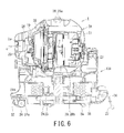
- Fig. 6 is a sectional view of another example illustrating the vacuum cleaner body of the electric vacuum cleaner according to the embodiment of the present invention.
- a vacuum cleaner body 2A of the electric vacuum cleaner 1 includes a base unit 17A, the elevation pivot support unit 18, and the main body 19.
- the base unit 17A includes a base unit main body 21A and the swivel base 22.
- the base unit main body 21A has a cord reel 35.
- the cord reel 35 is housed in the base unit main body 21A.
- the rotating shaft of the cord reel 35 is arranged to match the rotating shaft center of the swivel base 22.
- a power cord 36 is wound around the cord reel 35.
- the power cord 36 supplies power to the electric blower 27 of the main body 19.
- a power plug 37 is formed on a free end portion of the power cord 36.
- the vacuum cleaner body 2A prevents a pivot motion and a rotary motion of the main body 19 from causing the power cord 36 to twine or wind the vacuum cleaner body 2A regardless of the state of the base unit main body 21A in which the power cord 36 is provided.
- the electric vacuum cleaner 1 can suppress the curving of the dust collection hose 3 by causing the movement of the main body 19 to follow the movement of the dust collection hose 3 caused by the operation of the user of the electric vacuum cleaner 1 by means of the elevation pivot support unit 18, the swivel base 22, the casters 24.
- the electric vacuum cleaner 1 can suppress the reduction in suction performance caused by the curving of the dust collection hose 3.
- the electric vacuum cleaner 1 can avoid the curving of the dust collection hose 3.
- the electric vacuum cleaner 1 can orient the main body 19 in the direction on which the tensile force transmitted from the dust collection hose 3 acts by causing the movement of the main body 19 to follow the movement of the dust collection hose 3 caused by the operation of the user of the electric vacuum cleaner 1 by means of the elevation pivot support unit 18, the swivel base 22, the casters 24. Accordingly, the vacuum cleaner body 2 maintains its stable posture and receives the tensile force transmitted from the dust collection hose 3. Thus, the vacuum cleaner body 2 does not overturn or turn upside down and can perform smooth translational motion, rotary motion, and pivot motion. Thus, a sudden change in direction of the vacuum cleaner body 2 does not cause the casters 24 of the vacuum cleaner body 2 to hit the floor F, does not generate abnormal noise, and does not bring a feeling of discomfort to the user of the electric vacuum cleaner 1.
- the electric vacuum cleaner 1 performs the translational motion by the casters 24, the rotary motion by the casters 24 and the swivel base 22, and the pivot motion by the elevation pivot support unit 18 independently, and thus can ensure very light and smooth operation of the rotary motion and the pivot motion of the vacuum cleaner body 2 corresponding to the curving of the dust collection hose 3, and the translational motion of the vacuum cleaner body 2 caused by dragging of the dust collection hose 3.
- the electric vacuum cleaner 1 houses the secondary battery 23 in the base unit 17, and thus ensures a very light weight in the main body 19 and does not impair the handleability of the pivot motion.
- the electric vacuum cleaner 1 houses the power cord 36 and the cord reel 35 in the base unit main body 21A, thus preventing the power cord 36 from being wound or twined around the vacuum cleaner body 2 during the rotary motion of the swivel base 22 and the main body 19.
- the electric vacuum cleaner 1 provides the main body 19 with the main body hand grips 28a and 28b, thus ensuring enough portability of the main body 19.
- the electric vacuum cleaner 1 can provide the vacuum cleaner body 2 with excellent followability corresponding to the movement of the dust collection hose 3 and can suppress the reduction in dust suction force due to a curving of the dust collection hose 3.
Abstract
Description
- The present invention relates to an electric vacuum cleaner capable of suppressing reduction in dust suction force due to a curving of a dust collection hose.
- A conventional canister electric vacuum cleaner includes: a vacuum cleaner body having an electric blower which generates a negative pressure; a flexible dust collection hose connected to the vacuum cleaner body; and a hand operation pipe connected to the dust collection hose. When a user of the conventional electric vacuum cleaner pulls the hand operation pipe, the vacuum cleaner body runs.
- The vacuum cleaner body of the conventional electric vacuum cleaner includes a front wheel made of casters on the bottom surface thereof; and a pair of rear wheels provided on the side surface thereof. Further, the vacuum cleaner body has a connection port having a dust collection hose connected to a front surface in the advancing direction thereof.
- In addition, as another example, the vacuum cleaner body of a conventional electric vacuum cleaner includes a pair of wheels having an area larger than the projection thereof and a connection port having a dust collection hose connected to a front surface in the advancing direction thereof. (For example, see Patent Document 1).
Patent Document 1: Japanese Patent Laid-Open No.2003-190052 - The conventional electric vacuum cleaner has a connection port which is fixedly opened in front of the advancing direction of the vacuum cleaner body. Thus, handling of the dust collection hose without movement of the vacuum cleaner body may likely cause a curving of the dust collection hose. For example, on a substantially horizontal floor such as a floor surface, the dust collection hose moves up and down according to the back and forth movement of a floor suction fitting. In addition, on a substantially vertical floor such as a wall surface, the dust collection hose is oriented vertically upward. Such a movement of the dust collection hose is absorbed by the curving of the dust collection hose with respect to the connection port fixedly provided to the vacuum cleaner body. At this time, the curving of the dust collection hose reduces the suction performance of the electric vacuum cleaner. If the dust collection hose is blocked due to the curving, an excessive load is applied to the electric blower.
- Further, the direction of the vacuum cleaner body is variously changed with the cleaning operation of the user of the electric vacuum cleaner. However, the conventional electric vacuum cleaner has a problem in that the vacuum cleaner body overturns or turns upside down depending on the direction of dragging the dust collection hose.
- Further, a sudden change in direction of the vacuum cleaner body caused by dragging of the dust collection hose causes a momentary rise of a front portion of the vacuum cleaner body, which causes a caster provided on a bottom surface of the vacuum cleaner body to hit the floor, which generates abnormal noise, which brings a feeling of discomfort to the user of the electric vacuum cleaner.
- Meanwhile, the electric vacuum cleaner disclosed in
Patent Document 1 attempts to cause the vacuum cleaner body to follow the tensile force transmitted from the dust collection hose to the vacuum cleaner body. However, it is difficult for the electric vacuum cleaner disclosed inPatent Document 1 to achieve a balance between a translational motion of the vacuum cleaner body along the floor caused by dragging of the dust collection hose, a pivot motion of the vacuum cleaner body caused by a vertical movement of the dust collection hose, and a rotary motion of the vacuum cleaner body caused by a horizontal movement of the dust collection hose; and the suppression of the curving of the dust collection hose; by a pair of wheels provided on a side surface of the main body and a position of the center of gravity of the vacuum cleaner body. For example, an attempt to drag the dust collection hose to rotate the vacuum cleaner body causes the vacuum cleaner body to rotate about a rotational axis having a contact point in any one of the pair of wheels. Accordingly, the dust collection hose is excessively curved, thereby reducing the suction performance of the electric vacuum cleaner. - The present invention proposes an electric vacuum cleaner having a vacuum cleaner body with excellent followability corresponding to the movement of the dust collection hose and capable of suppressing reduction in dust suction force due to a curving of the dust collection hose.
- In order to solve the above problems, an electric vacuum cleaner according to the present invention comprises: a base unit; an elevation pivot support unit provided on the base unit; a main body pivotably supported by the elevation pivot support unit; a connection pipe having a central axis along a surface orthogonal to the pivot axis of the main body; a dust separation/collection unit housed in the main body and communicatively connected to the connection pipe; an electric blower housed in the main body and communicatively connected to the dust separation/collection unit; and a flexible dust collection hose connected to the connection pipe and communicatively connected to the dust separation/ collection unit.
- Thus, the present invention can propose an electric vacuum cleaner having a vacuum cleaner body with excellent followability corresponding to the movement of the dust collection hose and capable of suppressing reduction in dust suction force due to a curving of the dust collection hose.
-
-
Fig. 1 is an external perspective view illustrating an electric vacuum cleaner according to an embodiment of the present invention. -
Fig. 2 is a front view of a vacuum cleaner body of the electric vacuum cleaner according to the embodiment of the present invention. -
Fig. 3 is a plan view of the vacuum cleaner body of the electric vacuum cleaner according to the embodiment of the present invention. -
Fig. 4 is a side view of the vacuum cleaner body of the electric vacuum cleaner according to the embodiment of the present invention. -
Fig. 5 is a sectional view illustrating the vacuum cleaner body of the electric vacuum cleaner according to the embodiment of the present invention. -
Fig. 6 is a sectional view of another example illustrating the vacuum cleaner body of the electric vacuum cleaner according to the embodiment of the present invention. -
- 1
- electric vacuum cleaner
- 2, 2A
- vacuum cleaner body
- 2a
- connection port
- 3
- dust collection hose
- 4
- hand operation pipe
- 5
- gripping part
- 6
- operation unit
- 6a
- off switch
- 6b
- on switch
- 7
- extension tube
- 8
- floor suction fitting
- 17, 17A
- base unit
- 18
- elevation pivot support unit
- 19
- main body
- 21, 21A
- base unit main body
- 22
- swivel base
- 23
- secondary battery
- 24
- caster
- 24a
- axle
- 26
- dust separation/collection unit
- 27
- electric blower
- 28
- main body hand grip
- 30
- click mechanism
- 30a
- locking claw
- 30b
- locking recess
- 32
- caster shaft
- 33
- connection pipe
- 35
- cord reel
- 36
- power cord
- 37
- power plug
- An embodiment of an electric blower according to the present invention will be described by referring to the
Figs. 1 to 6 . -
Fig. 1 is an external perspective view illustrating an electric vacuum cleaner according to an embodiment of the present invention. -
Fig. 2 is a front view of a vacuum cleaner body of the electric vacuum cleaner according to the embodiment of the present invention. -
Fig. 3 is a plan view of the vacuum cleaner body of the electric vacuum cleaner according to the embodiment of the present invention. -
Fig. 4 is a side view of the vacuum cleaner body of the electric vacuum cleaner according to the embodiment of the present invention. - As illustrated in
Figs. 1 to 4 , theelectric vacuum cleaner 1 according to the present embodiment includes avacuum cleaner body 2, adust collection hose 3, a hand operation pipe 4, a gripping part 5, anoperation unit 6, anextension tube 7, and a floor suction fitting 8. - The
vacuum cleaner body 2 includes aconnection port 2a. One end of thedust collection hose 3 is connected to theconnection port 2a in an attachable and detachable manner. - The
vacuum cleaner body 2 includes: abase unit 17 placed on a floor F; an elevationpivot support unit 18 provided on thebase unit 17; and amain body 19 pivotably supported about a pivot axis x (in the direction indicated by a solid arrow Rx inFigs. 1 and4 ) of the elevationpivot support unit 18. - The
base unit 17 includes a base unitmain body 21 placed on the floor F; aswivel base 22 rotatably supported by the base unitmain body 21; and asecondary battery 23 supplying power to themain body 19. - At least three casters 24 (wheels) are attached to the bottom surface of the base unit
main body 21. When thevacuum cleaner body 2 is placed on the substantially horizontal floor F, thecasters 24 are arranged such that an orthographic projection position of the center of gravity of thevacuum cleaner body 2 to the floor F is inside a polygon with eachcaster 24 at an apex thereof, such as a triangle for threecasters 24. Specifically, thecasters 24 are arranged at substantially equal spacings near the outer circumference of the bottom surface of the base unitmain body 21. Thus, thevacuum cleaner body 2 can stably rotate and run on the floor F due to thecasters 24. - The
swivel base 22 is rotatably supported about a rotational axis z (in the direction indicated by a solid arrow Rz inFigs. 1 and3 ) of the base unitmain body 21. When thevacuum cleaner body 2 is placed on the floor F, the rotational axis z is positioned in a normal direction of the floor F. Specifically, when thevacuum cleaner body 2 is placed on the floor F such as a substantially horizontal floor, the rotational axis z is substantially vertical. Theswivel base 22 has the elevationpivot support unit 18. - The
secondary battery 23 is housed in thebase unit 17. Specifically, thesecondary battery 23 is positioned around themain body 19. Note that thesecondary battery 23 may be positioned so as to surround the entire circumference of themain body 19, or may be positioned so as to surround only the side circumference of themain body 19 near the elevationpivot support unit 18. Further, thesecondary battery 23 may be housed in any one of the base unitmain body 21 and theswivel base 22. - The elevation
pivot support unit 18 pivotably supports themain body 19 about the pivot axis x. When thevacuum cleaner body 2 is placed on the floor F such as a substantially horizontal floor, the pivot axis x is substantially parallel to the floor F. - The
main body 19 is pivotably supported by the elevationpivot support unit 18 from a substantially parallel state in one direction to a substantially parallel state in the other direction with respect to the floor F on which thebase unit 17 is placed; and is rotatably supported so as to be rotated 360° about the normal line of the floor by theswivel base 22. Themain body 19 and theswivel base 22 are integrally rotatably supported by the base unitmain body 21. Themain body 19 includes the dust separation/collection unit 26 and theelectric blower 27. Further, themain body 19 has a main body hand grip 28 (main body gripper unit) and a main body exhaust port (unillustrated) through which air is exhausted from theelectric blower 27. - The
main body 19 has theconnection port 2a to which thedust collection hose 3 is connected. When thedust collection hose 3 is dragged to pull thevacuum cleaner body 2, themain body 19 appropriately moves up and down with respect to the floor F on which thebase unit 17 is placed, thereby suppressing the curving of thedust collection hose 3. Specifically, as illustrated inFig. 4 , themain body 19 appropriately moves up and down following the dragging of thedust collection hose 3. For example, when thedust collection hose 3 is dragged in one direction substantially horizontal to the floor, themain body 19 makes theconnection port 2a follow in one substantially horizontal direction (solid arrow A inFig. 4 ). Further, when thedust collection hose 3 is dragged in a direction substantially vertical to the floor, themain body 19 makes theconnection port 2a follow in a substantially upward direction (solid arrow B inFig. 4 ). Furthermore, when thedust collection hose 3 is dragged in the other direction substantially horizontal to the floor, themain body 19 makes theconnection port 2a follow in the other substantially horizontal direction (solid arrow C inFig. 4 ).
Still further, themain body 19 appropriately changes the direction of theconnection port 2a following the dragging of thedust collection hose 3 in a pivotable range. Thus, theelectric vacuum cleaner 1 can suppress thedust collection hose 3 from being curved following the dragging of thevacuum cleaner body 2 and can suppress reduction in suction performance due to the curving of thedust collection hose 3. - The
vacuum cleaner body 2 has a click mechanism 30 (attachment/ detachment mechanism). Theclick mechanism 30 includes a locking claw 30a formed on the elevationpivot support unit 18; and a locking recess formed on themain body 19. Theclick mechanism 30 is configured such that themain body 19 can be temporarily fixed at a predetermined depression angle or elevation angle by the locking claw 30a and the locking recess 30b which are mutually attachable and detachable. When the locking claw 30a and the locking recess 30b are attached to each other, theclick mechanism 30 temporarily fixes the pivotablemain body 19 at an appropriate pivot position. Specifically, when thevacuum cleaner body 2 is placed on the floor F such as a substantially horizontal floor, theclick mechanism 30 can be configured such that theconnection port 2a temporarily fixes themain body 19 in a vertically upward state. - The
dust collection hose 3 is formed into a flexible, curvable, elongate, and substantially cylindrical shape. One end of thedust collection hose 3 is connected to theconnection port 2a in an attachable and detachable manner. Thedust collection hose 3 is communicatively connected to the inside of thevacuum cleaner body 2. - One end of the hand operation pipe 4 is provided in the other end of the
dust collection hose 3. The hand operation pipe 4 is communicatively connected to the inside of thevacuum cleaner body 2 through thedust collection hose 3. - The gripping part 5 is gripped by a user of the
electric vacuum cleaner 1 to operate theelectric vacuum cleaner 1. The gripping part 5 is projectingly provided in the other end portion of the hand operation pipe 4 and is formed to be curved toward one end portion of the hand operation pipe 4 where thedust collection hose 3 is provided. - The
operation unit 6 is provided on the gripping part 5. The user of theelectric vacuum cleaner 1 can set theelectric vacuum cleaner 1 to a plurality of drive modes by operating theoperation unit 6. Theoperation unit 6 includes anoff switch 6a for stopping the operation of theelectric vacuum cleaner 1 and an onswitch 6b for starting the operation of theelectric vacuum cleaner 1. - The
extension tube 7 is formed into a stretchable, elongate, and substantially cylindrical shape. Theextension tube 7 has a telescopic structure made by laminating a plurality of cylindrical bodies. On end of theextension tube 7 is connected to the other end of the hand operation pipe 4 in an attachable and detachable manner. Theextension tube 7 is communicatively connected to the inside of thevacuum cleaner body 2 through the hand operation pipe 4 and thedust collection hose 3. - The floor suction fitting 8 is connected to one end of the
extension tube 7 in an attachable and detachable manner. The floor suction fitting 8 is communicatively connected to the inside of thevacuum cleaner body 2 through theextension tube 7, the hand operation pipe 4, and thedust collection hose 3. The floor suction fitting 8 has a suction port (unillustrated). When the floor suction fitting 8 is placed on a floor F , the suction port faces the floor F. - When an on
switch 6b of theoperation unit 6 is pressed, theelectric vacuum cleaner 1 operates such that theelectric blower 27 starts operating and a negative pressure acts on the dust separation/collection unit 26. The negative pressure acts on the floor suction fitting 8 from theconnection port 2a, passing through thedust collection hose 3, the hand operation pipe 4, and theextension tube 7. Then, theelectric vacuum cleaner 1 sucks air together with dust accumulated on the floor F from the suction port of the floor suction fitting 8 to clean the floor F. The dust-containing air drawn in the floor suction fitting 8 is separated into air and dust by the dust separation/collection unit 26 housed in thevacuum cleaner body 2. The separated dust is collected in the dust separation/collection unit 26. Meanwhile, the separated air passes through theelectric blower 27 and is discharged from the main body exhaust port to outside thevacuum cleaner body 2. -
Fig. 5 is a sectional view illustrating the vacuum cleaner body of the electric vacuum cleaner according to the embodiment of the present invention. - As illustrated in
Fig. 5 , thevacuum cleaner body 2 of theelectric vacuum cleaner 1 includes thebase unit 17, the elevationpivot support unit 18, and themain body 19. - The
base unit 17 includes the base unitmain body 21 and theswivel base 22. - The
caster 24 of the base unitmain body 21 is rotatably supported by acaster shaft 32 provided on the bottom surface of the base unitmain body 21. The rotational axis Rc of eachcaster shaft 32 is configured to be substantially vertical to the floor F on which thebase unit 17 is placed and on which thecaster 24 contacts. Eachcaster shaft 32 is configured to be parallel to each other. The rotational axis Rc of thecaster shaft 32 does not cross theaxle 24a of thecaster 24 and is located in a mutually twisted position. - The
main body 19 includes aconnection pipe 33 having theconnection port 2a of thevacuum cleaner body 2; the dust separation/collection unit 26 communicatively connected to theconnection pipe 33; and theelectric blower 27 communicatively connected to the dust separation/collection unit 26. - The opening end of the
connection pipe 33 is theconnection port 2a of thevacuum cleaner body 2. The central axis c of theconnection pipe 33 is arranged in any one of the directions along a surface (for example, the cross section ofFig. 5 ) orthogonal to the pivot axis x. More specifically, theconnection pipe 33 is arranged in a position where the central axis c thereof is along the surface orthogonal to the pivot axis x, theconnection port 2a is opened in a direction farther away from the pivot axis x, and theconnection pipe 33 is farthest from the pivot axis x. - Further, the
main body 19 has main body hand grips 28a and 28b (a main body gripper unit and a second main body gripper unit) axisymmetrically arranged about pivot axis x. The main body hand grip 28a is grippably provided in a pivot position of themain body 19 in a substantially parallel state in one direction to the floor F on which thebase unit 17 is placed. The main body hand grip 28b is grippably provided in a pivot position of themain body 19 in a substantially parallel state in the other direction to the floor F on which thebase unit 17 is placed. Thevacuum cleaner body 2 can be carried in any state of themain body 19 oriented in any pivot direction by the main body hand grips 28a and 28b. The main body hand grips 28a and 28b improve the portability of thevacuum cleaner body 2. - Now, a cleaning operation of the
electric vacuum cleaner 1 according to the present embodiment will be described. - First, the user of the
electric vacuum cleaner 1 connects thedust collection hose 3 to theconnection port 2a of thevacuum cleaner body 2. Then, the user of theelectric vacuum cleaner 1 connects theextension tube 7 to the hand operation pipe 4. Then, the user of theelectric vacuum cleaner 1 connects the floor suction fitting 8 to theextension tube 7. - Next, the user of the
electric vacuum cleaner 1 places the floor suction fitting 8 on the floor F and operates the onswitch 6b with the gripping part 5 being gripped. Then, theelectric blower 27 operates according to the operation mode set by the onswitch 6b. - Next, the user of the
electric vacuum cleaner 1 moves the hand operation pipe 4 and theextension tube 7 with the gripping part 5 being gripped to run the floor suction fitting 8. - At this time, for example, when the user of the
electric vacuum cleaner 1 repeatedly moves the gripping part 5 back and forth to clean the floor F, the hand operation pipe 4, theextension tube 7, and the floor suction fitting 8 reciprocate back and forth. With this movement, themain body 19 of thevacuum cleaner body 2 moves up and down about the pivot axis x of the elevationpivot support unit 18 following the curving of thedust collection hose 3. This also applied to a case in which the user of theelectric vacuum cleaner 1 repeatedly moves the gripping part 5 up and down to clean a wall. - When the user of the
electric vacuum cleaner 1 suddenly changes the advancing direction to pull the gripping part 5, thevacuum cleaner body 2 rotates about the rotational axis z following the curving of thedust collection hose 3 by means of theswivel base 22 or thecasters 24. - Further, when the user of the
electric vacuum cleaner 1 pulls the gripping part 5 to leave the to-be-cleaned place, thevacuum cleaner body 2 moves up or down and turns following the curving of thedust collection hose 3 by means of the elevationpivot support unit 18, theswivel base 22, and thecasters 24 to run on the floor F. - Thus, the
vacuum cleaner body 2 suppresses the curving of thedust collection hose 3 by causing the movement of themain body 19 to follow the curving of thedust collection hose 3 caused by the operation of the user of theelectric vacuum cleaner 1 by means of the elevationpivot support unit 18, theswivel base 22, thecasters 24. Further, thevacuum cleaner body 2 can orient theconnection port 2a of themain body 19 in the direction on which the tensile force transmitted from thedust collection hose 3 acts. Suppression of the curving of thedust collection hose 3 suppresses the reduction in suction performance of theelectric vacuum cleaner 1 caused by the curving of thedust collection hose 3. - Meanwhile, the dust on the floor F is drawn together with air in the suction port of the floor suction fitting 8. The dust-containing air sucked into the floor suction fitting 8 passes through the
extension tube 7, the hand operation pipe 4, and thedust collection hose 3 in that order and passes through theconnection port 2a of thevacuum cleaner body 2 and is drawn inside thevacuum cleaner body 2. - The dust-containing air drawn inside the
vacuum cleaner body 2 is guided to the dust separation/collection unit 26. Here, the dust-containing air is separated into air and dust by the dust separation/collection unit 26. The separated dust is collected by the dust separation/collection unit 26. Meanwhile, the separated air is drawn in by theelectric blower 27, passes through theelectric blower 27 by cooling theelectric blower 27, and then is discharged from the main body exhaust port to outside thevacuum cleaner body 2. -
Fig. 6 is a sectional view of another example illustrating the vacuum cleaner body of the electric vacuum cleaner according to the embodiment of the present invention. - As illustrated in
Fig. 6 , avacuum cleaner body 2A of theelectric vacuum cleaner 1 includes abase unit 17A, the elevationpivot support unit 18, and themain body 19. - The
base unit 17A includes a base unitmain body 21A and theswivel base 22. - The base unit
main body 21A has acord reel 35. Thecord reel 35 is housed in the base unitmain body 21A. The rotating shaft of thecord reel 35 is arranged to match the rotating shaft center of theswivel base 22. Apower cord 36 is wound around thecord reel 35. Thepower cord 36 supplies power to theelectric blower 27 of themain body 19. Apower plug 37 is formed on a free end portion of thepower cord 36. - Thus configured the
vacuum cleaner body 2A prevents a pivot motion and a rotary motion of themain body 19 from causing thepower cord 36 to twine or wind thevacuum cleaner body 2A regardless of the state of the base unitmain body 21A in which thepower cord 36 is provided. - The
electric vacuum cleaner 1 according to the present embodiment can suppress the curving of thedust collection hose 3 by causing the movement of themain body 19 to follow the movement of thedust collection hose 3 caused by the operation of the user of theelectric vacuum cleaner 1 by means of the elevationpivot support unit 18, theswivel base 22, thecasters 24. Thus, theelectric vacuum cleaner 1 can suppress the reduction in suction performance caused by the curving of thedust collection hose 3. Further, theelectric vacuum cleaner 1 can avoid the curving of thedust collection hose 3. - Further, the
electric vacuum cleaner 1 according to the present embodiment can orient themain body 19 in the direction on which the tensile force transmitted from thedust collection hose 3 acts by causing the movement of themain body 19 to follow the movement of thedust collection hose 3 caused by the operation of the user of theelectric vacuum cleaner 1 by means of the elevationpivot support unit 18, theswivel base 22, thecasters 24. Accordingly, thevacuum cleaner body 2 maintains its stable posture and receives the tensile force transmitted from thedust collection hose 3. Thus, thevacuum cleaner body 2 does not overturn or turn upside down and can perform smooth translational motion, rotary motion, and pivot motion. Thus, a sudden change in direction of thevacuum cleaner body 2 does not cause thecasters 24 of thevacuum cleaner body 2 to hit the floor F, does not generate abnormal noise, and does not bring a feeling of discomfort to the user of theelectric vacuum cleaner 1. - Further, the
electric vacuum cleaner 1 according to the present embodiment performs the translational motion by thecasters 24, the rotary motion by thecasters 24 and theswivel base 22, and the pivot motion by the elevationpivot support unit 18 independently, and thus can ensure very light and smooth operation of the rotary motion and the pivot motion of thevacuum cleaner body 2 corresponding to the curving of thedust collection hose 3, and the translational motion of thevacuum cleaner body 2 caused by dragging of thedust collection hose 3. - Furthermore, the
electric vacuum cleaner 1 according to the present embodiment houses thesecondary battery 23 in thebase unit 17, and thus ensures a very light weight in themain body 19 and does not impair the handleability of the pivot motion. - Furthermore, the
electric vacuum cleaner 1 according to the present embodiment houses thepower cord 36 and thecord reel 35 in the base unitmain body 21A, thus preventing thepower cord 36 from being wound or twined around thevacuum cleaner body 2 during the rotary motion of theswivel base 22 and themain body 19. - Furthermore, the
electric vacuum cleaner 1 according to the present embodiment provides themain body 19 with the main body hand grips 28a and 28b, thus ensuring enough portability of themain body 19. - Thus, the
electric vacuum cleaner 1 according to the present embodiment can provide thevacuum cleaner body 2 with excellent followability corresponding to the movement of thedust collection hose 3 and can suppress the reduction in dust suction force due to a curving of thedust collection hose 3.
Claims (10)
- An electric vacuum cleaner comprising:a base unit;an elevation pivot support unit provided on the base unit;a main body pivotably supported by the elevation pivot support unit;a connection pipe having a central axis along a surface orthogonal to a pivot axis of the main body;a dust separation/collection unit housed in the main body and communicatively connected to the connection pipe;an electric blower housed in the main body and communicatively connected to the dust separation/collection unit; anda flexible dust collection hose connected to the connection pipe and communicatively connected to the dust separation/collection unit.
- The electric vacuum cleaner according to claim 1, wherein the base unit has at least three wheels.
- The electric vacuum cleaner according to claim 2, wherein the wheel is rotatably provided about a rotational axis vertical to a surface contacted by the wheel and an axle of the wheel and the rotational axis are in a skewed position.
- The electric vacuum cleaner according to any one of claims 1 to 3, wherein the base unit includes a base unit main body; and a swivel base rotatably supported by the base unit main body and having the elevation pivot support unit.
- The electric vacuum cleaner according to any one of claims 1 to 4, further comprising a secondary battery housed in the base unit and supplying power to the electric blower provided in a position surrounding the main body.
- The electric vacuum cleaner according to claim 4, further comprising a power cord provided in the base unit main body and supplying power to the electric blower.
- The electric vacuum cleaner according to any one of claims 1 to 6, wherein the main body is pivotably supported from a substantially parallel state in one direction to a substantially parallel state in another direction with respect to a surface on which the base unit is placed.
- The electric vacuum cleaner according to any one of claims 1 to 7, further comprising an attachment/detachment mechanism which can temporarily fix the main body by orienting the central axis of the connection pipe in a normal line direction of a surface on which the base unit is placed.
- The electric vacuum cleaner according to any one of claims 1 to 8, further comprising a main body gripper unit which can be gripped in a pivot position of the main body in a substantially parallel state in one direction to a surface on which the base unit is placed.
- The electric vacuum cleaner according to any one of claims 1 to 9, further comprising a second main body gripper unit which can be gripped in a pivot position of the main body in a substantially parallel state in another direction to a surface on which the base unit is placed.
Applications Claiming Priority (2)
| Application Number | Priority Date | Filing Date | Title |
|---|---|---|---|
| JP2008301583A JP5135182B2 (en) | 2008-11-26 | 2008-11-26 | Electric vacuum cleaner |
| PCT/JP2009/069922 WO2010061874A1 (en) | 2008-11-26 | 2009-11-26 | Electric cleaner |
Publications (3)
| Publication Number | Publication Date |
|---|---|
| EP2368472A1 true EP2368472A1 (en) | 2011-09-28 |
| EP2368472A4 EP2368472A4 (en) | 2014-04-16 |
| EP2368472B1 EP2368472B1 (en) | 2016-12-21 |
Family
ID=42225744
Family Applications (1)
| Application Number | Title | Priority Date | Filing Date |
|---|---|---|---|
| EP09829119.8A Not-in-force EP2368472B1 (en) | 2008-11-26 | 2009-11-26 | Electric cleaner |
Country Status (6)
| Country | Link |
|---|---|
| EP (1) | EP2368472B1 (en) |
| JP (1) | JP5135182B2 (en) |
| KR (1) | KR101284389B1 (en) |
| CN (1) | CN102227184B (en) |
| RU (1) | RU2472421C1 (en) |
| WO (1) | WO2010061874A1 (en) |
Cited By (3)
| Publication number | Priority date | Publication date | Assignee | Title |
|---|---|---|---|---|
| US20140359967A1 (en) * | 2013-06-11 | 2014-12-11 | Samsung Electronics Co., Ltd. | Vacuum cleaner |
| WO2014200239A1 (en) * | 2013-06-12 | 2014-12-18 | Samsung Electronics Co., Ltd. | Vacuum cleaner |
| EP2630903A3 (en) * | 2012-02-21 | 2017-03-29 | Lg Electronics Inc. | Autonomous mobile cleaner and method for moving the same |
Families Citing this family (2)
| Publication number | Priority date | Publication date | Assignee | Title |
|---|---|---|---|---|
| GB2542197B (en) * | 2015-09-14 | 2017-12-20 | Dyson Technology Ltd | Handle assembly for a vacuum cleaner |
| AU2017226605B2 (en) * | 2016-02-29 | 2019-06-13 | Lg Electronics Inc. | Vacuum cleaner |
Citations (4)
| Publication number | Priority date | Publication date | Assignee | Title |
|---|---|---|---|---|
| EP0362895A1 (en) * | 1988-10-07 | 1990-04-11 | Hitachi, Ltd. | Electric cleaner and method for producing the same |
| EP1129657A1 (en) * | 2000-03-01 | 2001-09-05 | Matsushita Electric Industrial Co., Ltd. | Electric cleaner |
| JP2002355199A (en) * | 2001-09-20 | 2002-12-10 | Hitachi Ltd | Vacuum cleaner |
| KR20060034851A (en) * | 2004-10-20 | 2006-04-26 | 삼성광주전자 주식회사 | Ac/dc compatible vacuum cleaner |
Family Cites Families (7)
| Publication number | Priority date | Publication date | Assignee | Title |
|---|---|---|---|---|
| JPH03111247U (en) * | 1990-03-02 | 1991-11-14 | ||
| JP2508006Y2 (en) * | 1990-03-02 | 1996-08-21 | 株式会社日立製作所 | Electric vacuum cleaner |
| JPH1147043A (en) * | 1997-07-30 | 1999-02-23 | Matsushita Electric Ind Co Ltd | Vacuum cleaner |
| JP2001017357A (en) * | 1999-07-08 | 2001-01-23 | Sharp Corp | Vacuum cleaner |
| JP2001314356A (en) * | 2000-03-01 | 2001-11-13 | Matsushita Electric Ind Co Ltd | Electric vacuum cleaner |
| JP3781676B2 (en) * | 2001-12-27 | 2006-05-31 | シャープ株式会社 | Vacuum cleaner |
| JP4172288B2 (en) * | 2003-02-20 | 2008-10-29 | 松下電器産業株式会社 | Vacuum cleaner |
-
2008
- 2008-11-26 JP JP2008301583A patent/JP5135182B2/en not_active Expired - Fee Related
-
2009
- 2009-11-26 CN CN200980147551.8A patent/CN102227184B/en not_active Expired - Fee Related
- 2009-11-26 RU RU2011126190/12A patent/RU2472421C1/en not_active IP Right Cessation
- 2009-11-26 WO PCT/JP2009/069922 patent/WO2010061874A1/en active Application Filing
- 2009-11-26 KR KR1020117011922A patent/KR101284389B1/en active IP Right Grant
- 2009-11-26 EP EP09829119.8A patent/EP2368472B1/en not_active Not-in-force
Patent Citations (4)
| Publication number | Priority date | Publication date | Assignee | Title |
|---|---|---|---|---|
| EP0362895A1 (en) * | 1988-10-07 | 1990-04-11 | Hitachi, Ltd. | Electric cleaner and method for producing the same |
| EP1129657A1 (en) * | 2000-03-01 | 2001-09-05 | Matsushita Electric Industrial Co., Ltd. | Electric cleaner |
| JP2002355199A (en) * | 2001-09-20 | 2002-12-10 | Hitachi Ltd | Vacuum cleaner |
| KR20060034851A (en) * | 2004-10-20 | 2006-04-26 | 삼성광주전자 주식회사 | Ac/dc compatible vacuum cleaner |
Non-Patent Citations (1)
| Title |
|---|
| See also references of WO2010061874A1 * |
Cited By (15)
| Publication number | Priority date | Publication date | Assignee | Title |
|---|---|---|---|---|
| EP2630903A3 (en) * | 2012-02-21 | 2017-03-29 | Lg Electronics Inc. | Autonomous mobile cleaner and method for moving the same |
| US9661966B2 (en) | 2013-06-11 | 2017-05-30 | Samsung Electronics Co., Ltd. | Vacuum cleaner |
| WO2014200229A1 (en) * | 2013-06-11 | 2014-12-18 | Samsung Electronics Co., Ltd. | Vacuum cleaner |
| US20140359967A1 (en) * | 2013-06-11 | 2014-12-11 | Samsung Electronics Co., Ltd. | Vacuum cleaner |
| AU2014278964A1 (en) * | 2013-06-11 | 2015-11-12 | Samsung Electronics Co., Ltd. | Vacuum cleaner |
| RU2617981C1 (en) * | 2013-06-11 | 2017-04-28 | Самсунг Электроникс Ко., Лтд. | Vacuum cleaner |
| US9247854B2 (en) * | 2013-06-11 | 2016-02-02 | Samsung Electronics Co., Ltd. | Vacuum cleaner |
| AU2014278964B2 (en) * | 2013-06-11 | 2016-06-30 | Samsung Electronics Co., Ltd. | Vacuum cleaner |
| KR20140144879A (en) * | 2013-06-12 | 2014-12-22 | 삼성전자주식회사 | Vacuum cleaner |
| US9420926B2 (en) | 2013-06-12 | 2016-08-23 | Samsung Electronics Co., Ltd. | Vacuum cleaner |
| EP2961304A4 (en) * | 2013-06-12 | 2016-11-02 | Samsung Electronics Co Ltd | Vacuum cleaner |
| AU2014278974B2 (en) * | 2013-06-12 | 2016-07-07 | Samsung Electronics Co., Ltd. | Vacuum cleaner |
| CN105142479A (en) * | 2013-06-12 | 2015-12-09 | 三星电子株式会社 | Vacuum cleaner |
| WO2014200239A1 (en) * | 2013-06-12 | 2014-12-18 | Samsung Electronics Co., Ltd. | Vacuum cleaner |
| RU2647255C2 (en) * | 2013-06-12 | 2018-03-14 | Самсунг Электроникс Ко., Лтд. | Vacuum cleaner |
Also Published As
| Publication number | Publication date |
|---|---|
| KR101284389B1 (en) | 2013-07-09 |
| RU2472421C1 (en) | 2013-01-20 |
| EP2368472B1 (en) | 2016-12-21 |
| JP5135182B2 (en) | 2013-01-30 |
| KR20110089296A (en) | 2011-08-05 |
| WO2010061874A1 (en) | 2010-06-03 |
| EP2368472A4 (en) | 2014-04-16 |
| JP2010125008A (en) | 2010-06-10 |
| CN102227184B (en) | 2014-06-18 |
| CN102227184A (en) | 2011-10-26 |
Similar Documents
| Publication | Publication Date | Title |
|---|---|---|
| EP2368472B1 (en) | Electric cleaner | |
| JP2001314356A (en) | Electric vacuum cleaner | |
| JP5864976B2 (en) | Electric vacuum cleaner | |
| JP4613774B2 (en) | Electric vacuum cleaner | |
| EP2368471A1 (en) | Electric cleaner | |
| JP6121656B2 (en) | Vacuum cleaner and its suction port | |
| KR101322574B1 (en) | Vacuum cleaner hose assembly and vacuum cleaner | |
| KR20100086956A (en) | Electrical vacuum cleaner | |
| JP5118013B2 (en) | Electric vacuum cleaner | |
| JP2007135651A5 (en) | ||
| JP4779537B2 (en) | Vacuum cleaner | |
| JP3066369B2 (en) | Vacuum cleaner and its suction body | |
| JP5104534B2 (en) | Electric vacuum cleaner | |
| JP5300415B2 (en) | Electric vacuum cleaner | |
| JP3066368B2 (en) | Vacuum cleaner and its suction body | |
| JP2019025146A (en) | Vacuum cleaner | |
| JP4434970B2 (en) | Vacuum cleaner | |
| JP6056377B2 (en) | Electric vacuum cleaner | |
| JP7104593B2 (en) | Vacuum cleaner | |
| JP5973751B2 (en) | Electric vacuum cleaner | |
| JP2010125039A (en) | Electric vacuum cleaner | |
| JP2005027829A (en) | Vacuum cleaner | |
| JP2020114281A (en) | Vacuum cleaner | |
| JP2024015201A (en) | Cleaning tools, vacuum cleaners, and cordless vacuum cleaners | |
| JP2003265381A (en) | Vacuum cleaner |
Legal Events
| Date | Code | Title | Description |
|---|---|---|---|
| PUAI | Public reference made under article 153(3) epc to a published international application that has entered the european phase |
Free format text: ORIGINAL CODE: 0009012 |
|
| 17P | Request for examination filed |
Effective date: 20110620 |
|
| AK | Designated contracting states |
Kind code of ref document: A1 Designated state(s): AT BE BG CH CY CZ DE DK EE ES FI FR GB GR HR HU IE IS IT LI LT LU LV MC MK MT NL NO PL PT RO SE SI SK SM TR |
|
| DAX | Request for extension of the european patent (deleted) | ||
| A4 | Supplementary search report drawn up and despatched |
Effective date: 20140317 |
|
| RIC1 | Information provided on ipc code assigned before grant |
Ipc: A47L 5/36 20060101ALI20140311BHEP Ipc: A47L 9/00 20060101AFI20140311BHEP Ipc: A47L 9/24 20060101ALI20140311BHEP Ipc: A47L 9/28 20060101ALI20140311BHEP |
|
| GRAP | Despatch of communication of intention to grant a patent |
Free format text: ORIGINAL CODE: EPIDOSNIGR1 |
|
| INTG | Intention to grant announced |
Effective date: 20160719 |
|
| RAP1 | Party data changed (applicant data changed or rights of an application transferred) |
Owner name: TOSHIBA LIFESTYLE PRODUCTS & SERVICES CORPORATION |
|
| GRAS | Grant fee paid |
Free format text: ORIGINAL CODE: EPIDOSNIGR3 |
|
| GRAA | (expected) grant |
Free format text: ORIGINAL CODE: 0009210 |
|
| AK | Designated contracting states |
Kind code of ref document: B1 Designated state(s): AT BE BG CH CY CZ DE DK EE ES FI FR GB GR HR HU IE IS IT LI LT LU LV MC MK MT NL NO PL PT RO SE SI SK SM TR |
|
| REG | Reference to a national code |
Ref country code: GB Ref legal event code: FG4D |
|
| REG | Reference to a national code |
Ref country code: CH Ref legal event code: EP |
|
| REG | Reference to a national code |
Ref country code: IE Ref legal event code: FG4D |
|
| REG | Reference to a national code |
Ref country code: AT Ref legal event code: REF Ref document number: 854710 Country of ref document: AT Kind code of ref document: T Effective date: 20170115 |
|
| REG | Reference to a national code |
Ref country code: DE Ref legal event code: R096 Ref document number: 602009043292 Country of ref document: DE |
|
| PG25 | Lapsed in a contracting state [announced via postgrant information from national office to epo] |
Ref country code: LV Free format text: LAPSE BECAUSE OF FAILURE TO SUBMIT A TRANSLATION OF THE DESCRIPTION OR TO PAY THE FEE WITHIN THE PRESCRIBED TIME-LIMIT Effective date: 20161221 |
|
| REG | Reference to a national code |
Ref country code: LT Ref legal event code: MG4D |
|
| REG | Reference to a national code |
Ref country code: NL Ref legal event code: MP Effective date: 20161221 |
|
| PG25 | Lapsed in a contracting state [announced via postgrant information from national office to epo] |
Ref country code: SE Free format text: LAPSE BECAUSE OF FAILURE TO SUBMIT A TRANSLATION OF THE DESCRIPTION OR TO PAY THE FEE WITHIN THE PRESCRIBED TIME-LIMIT Effective date: 20161221 Ref country code: GR Free format text: LAPSE BECAUSE OF FAILURE TO SUBMIT A TRANSLATION OF THE DESCRIPTION OR TO PAY THE FEE WITHIN THE PRESCRIBED TIME-LIMIT Effective date: 20170322 Ref country code: NO Free format text: LAPSE BECAUSE OF FAILURE TO SUBMIT A TRANSLATION OF THE DESCRIPTION OR TO PAY THE FEE WITHIN THE PRESCRIBED TIME-LIMIT Effective date: 20170321 Ref country code: LT Free format text: LAPSE BECAUSE OF FAILURE TO SUBMIT A TRANSLATION OF THE DESCRIPTION OR TO PAY THE FEE WITHIN THE PRESCRIBED TIME-LIMIT Effective date: 20161221 |
|
| REG | Reference to a national code |
Ref country code: AT Ref legal event code: MK05 Ref document number: 854710 Country of ref document: AT Kind code of ref document: T Effective date: 20161221 |
|
| PG25 | Lapsed in a contracting state [announced via postgrant information from national office to epo] |
Ref country code: FI Free format text: LAPSE BECAUSE OF FAILURE TO SUBMIT A TRANSLATION OF THE DESCRIPTION OR TO PAY THE FEE WITHIN THE PRESCRIBED TIME-LIMIT Effective date: 20161221 Ref country code: HR Free format text: LAPSE BECAUSE OF FAILURE TO SUBMIT A TRANSLATION OF THE DESCRIPTION OR TO PAY THE FEE WITHIN THE PRESCRIBED TIME-LIMIT Effective date: 20161221 |
|
| PG25 | Lapsed in a contracting state [announced via postgrant information from national office to epo] |
Ref country code: NL Free format text: LAPSE BECAUSE OF FAILURE TO SUBMIT A TRANSLATION OF THE DESCRIPTION OR TO PAY THE FEE WITHIN THE PRESCRIBED TIME-LIMIT Effective date: 20161221 |
|
| PG25 | Lapsed in a contracting state [announced via postgrant information from national office to epo] |
Ref country code: CZ Free format text: LAPSE BECAUSE OF FAILURE TO SUBMIT A TRANSLATION OF THE DESCRIPTION OR TO PAY THE FEE WITHIN THE PRESCRIBED TIME-LIMIT Effective date: 20161221 Ref country code: RO Free format text: LAPSE BECAUSE OF FAILURE TO SUBMIT A TRANSLATION OF THE DESCRIPTION OR TO PAY THE FEE WITHIN THE PRESCRIBED TIME-LIMIT Effective date: 20161221 Ref country code: EE Free format text: LAPSE BECAUSE OF FAILURE TO SUBMIT A TRANSLATION OF THE DESCRIPTION OR TO PAY THE FEE WITHIN THE PRESCRIBED TIME-LIMIT Effective date: 20161221 Ref country code: IS Free format text: LAPSE BECAUSE OF FAILURE TO SUBMIT A TRANSLATION OF THE DESCRIPTION OR TO PAY THE FEE WITHIN THE PRESCRIBED TIME-LIMIT Effective date: 20170421 Ref country code: SK Free format text: LAPSE BECAUSE OF FAILURE TO SUBMIT A TRANSLATION OF THE DESCRIPTION OR TO PAY THE FEE WITHIN THE PRESCRIBED TIME-LIMIT Effective date: 20161221 |
|
| PG25 | Lapsed in a contracting state [announced via postgrant information from national office to epo] |
Ref country code: BG Free format text: LAPSE BECAUSE OF FAILURE TO SUBMIT A TRANSLATION OF THE DESCRIPTION OR TO PAY THE FEE WITHIN THE PRESCRIBED TIME-LIMIT Effective date: 20170321 Ref country code: ES Free format text: LAPSE BECAUSE OF FAILURE TO SUBMIT A TRANSLATION OF THE DESCRIPTION OR TO PAY THE FEE WITHIN THE PRESCRIBED TIME-LIMIT Effective date: 20161221 Ref country code: IT Free format text: LAPSE BECAUSE OF FAILURE TO SUBMIT A TRANSLATION OF THE DESCRIPTION OR TO PAY THE FEE WITHIN THE PRESCRIBED TIME-LIMIT Effective date: 20161221 Ref country code: SM Free format text: LAPSE BECAUSE OF FAILURE TO SUBMIT A TRANSLATION OF THE DESCRIPTION OR TO PAY THE FEE WITHIN THE PRESCRIBED TIME-LIMIT Effective date: 20161221 Ref country code: PT Free format text: LAPSE BECAUSE OF FAILURE TO SUBMIT A TRANSLATION OF THE DESCRIPTION OR TO PAY THE FEE WITHIN THE PRESCRIBED TIME-LIMIT Effective date: 20170421 Ref country code: PL Free format text: LAPSE BECAUSE OF FAILURE TO SUBMIT A TRANSLATION OF THE DESCRIPTION OR TO PAY THE FEE WITHIN THE PRESCRIBED TIME-LIMIT Effective date: 20161221 Ref country code: AT Free format text: LAPSE BECAUSE OF FAILURE TO SUBMIT A TRANSLATION OF THE DESCRIPTION OR TO PAY THE FEE WITHIN THE PRESCRIBED TIME-LIMIT Effective date: 20161221 Ref country code: BE Free format text: LAPSE BECAUSE OF FAILURE TO SUBMIT A TRANSLATION OF THE DESCRIPTION OR TO PAY THE FEE WITHIN THE PRESCRIBED TIME-LIMIT Effective date: 20161221 |
|
| REG | Reference to a national code |
Ref country code: DE Ref legal event code: R097 Ref document number: 602009043292 Country of ref document: DE |
|
| PLBE | No opposition filed within time limit |
Free format text: ORIGINAL CODE: 0009261 |
|
| STAA | Information on the status of an ep patent application or granted ep patent |
Free format text: STATUS: NO OPPOSITION FILED WITHIN TIME LIMIT |
|
| 26N | No opposition filed |
Effective date: 20170922 |
|
| PG25 | Lapsed in a contracting state [announced via postgrant information from national office to epo] |
Ref country code: DK Free format text: LAPSE BECAUSE OF FAILURE TO SUBMIT A TRANSLATION OF THE DESCRIPTION OR TO PAY THE FEE WITHIN THE PRESCRIBED TIME-LIMIT Effective date: 20161221 |
|
| PG25 | Lapsed in a contracting state [announced via postgrant information from national office to epo] |
Ref country code: SI Free format text: LAPSE BECAUSE OF FAILURE TO SUBMIT A TRANSLATION OF THE DESCRIPTION OR TO PAY THE FEE WITHIN THE PRESCRIBED TIME-LIMIT Effective date: 20161221 |
|
| PG25 | Lapsed in a contracting state [announced via postgrant information from national office to epo] |
Ref country code: MC Free format text: LAPSE BECAUSE OF FAILURE TO SUBMIT A TRANSLATION OF THE DESCRIPTION OR TO PAY THE FEE WITHIN THE PRESCRIBED TIME-LIMIT Effective date: 20161221 |
|
| PG25 | Lapsed in a contracting state [announced via postgrant information from national office to epo] |
Ref country code: LI Free format text: LAPSE BECAUSE OF NON-PAYMENT OF DUE FEES Effective date: 20171130 Ref country code: CH Free format text: LAPSE BECAUSE OF NON-PAYMENT OF DUE FEES Effective date: 20171130 |
|
| PG25 | Lapsed in a contracting state [announced via postgrant information from national office to epo] |
Ref country code: LU Free format text: LAPSE BECAUSE OF NON-PAYMENT OF DUE FEES Effective date: 20171126 |
|
| REG | Reference to a national code |
Ref country code: FR Ref legal event code: ST Effective date: 20180731 |
|
| REG | Reference to a national code |
Ref country code: IE Ref legal event code: MM4A |
|
| PG25 | Lapsed in a contracting state [announced via postgrant information from national office to epo] |
Ref country code: MT Free format text: LAPSE BECAUSE OF NON-PAYMENT OF DUE FEES Effective date: 20171126 |
|
| PG25 | Lapsed in a contracting state [announced via postgrant information from national office to epo] |
Ref country code: IE Free format text: LAPSE BECAUSE OF NON-PAYMENT OF DUE FEES Effective date: 20171126 Ref country code: FR Free format text: LAPSE BECAUSE OF NON-PAYMENT OF DUE FEES Effective date: 20171130 |
|
| PGFP | Annual fee paid to national office [announced via postgrant information from national office to epo] |
Ref country code: DE Payment date: 20181113 Year of fee payment: 10 |
|
| PGFP | Annual fee paid to national office [announced via postgrant information from national office to epo] |
Ref country code: GB Payment date: 20181121 Year of fee payment: 10 |
|
| PG25 | Lapsed in a contracting state [announced via postgrant information from national office to epo] |
Ref country code: HU Free format text: LAPSE BECAUSE OF FAILURE TO SUBMIT A TRANSLATION OF THE DESCRIPTION OR TO PAY THE FEE WITHIN THE PRESCRIBED TIME-LIMIT; INVALID AB INITIO Effective date: 20091126 |
|
| PG25 | Lapsed in a contracting state [announced via postgrant information from national office to epo] |
Ref country code: CY Free format text: LAPSE BECAUSE OF NON-PAYMENT OF DUE FEES Effective date: 20161221 |
|
| PG25 | Lapsed in a contracting state [announced via postgrant information from national office to epo] |
Ref country code: MK Free format text: LAPSE BECAUSE OF FAILURE TO SUBMIT A TRANSLATION OF THE DESCRIPTION OR TO PAY THE FEE WITHIN THE PRESCRIBED TIME-LIMIT Effective date: 20161221 |
|
| PG25 | Lapsed in a contracting state [announced via postgrant information from national office to epo] |
Ref country code: TR Free format text: LAPSE BECAUSE OF FAILURE TO SUBMIT A TRANSLATION OF THE DESCRIPTION OR TO PAY THE FEE WITHIN THE PRESCRIBED TIME-LIMIT Effective date: 20161221 |
|
| REG | Reference to a national code |
Ref country code: DE Ref legal event code: R119 Ref document number: 602009043292 Country of ref document: DE |
|
| GBPC | Gb: european patent ceased through non-payment of renewal fee |
Effective date: 20191126 |
|
| PG25 | Lapsed in a contracting state [announced via postgrant information from national office to epo] |
Ref country code: GB Free format text: LAPSE BECAUSE OF NON-PAYMENT OF DUE FEES Effective date: 20191126 Ref country code: DE Free format text: LAPSE BECAUSE OF NON-PAYMENT OF DUE FEES Effective date: 20200603 |