EP2367264A1 - Rotierende elektrische Maschine mit Stator mit konzentrierten Wicklungen - Google Patents
Rotierende elektrische Maschine mit Stator mit konzentrierten Wicklungen Download PDFInfo
- Publication number
- EP2367264A1 EP2367264A1 EP11305296A EP11305296A EP2367264A1 EP 2367264 A1 EP2367264 A1 EP 2367264A1 EP 11305296 A EP11305296 A EP 11305296A EP 11305296 A EP11305296 A EP 11305296A EP 2367264 A1 EP2367264 A1 EP 2367264A1
- Authority
- EP
- European Patent Office
- Prior art keywords
- tooth
- stator
- carcass
- teeth
- ferrule
- Prior art date
- Legal status (The legal status is an assumption and is not a legal conclusion. Google has not performed a legal analysis and makes no representation as to the accuracy of the status listed.)
- Granted
Links
- 238000004804 winding Methods 0.000 title claims abstract description 59
- 230000002950 deficient Effects 0.000 claims abstract description 28
- 238000000034 method Methods 0.000 claims abstract description 7
- 238000000605 extraction Methods 0.000 claims description 7
- 239000004020 conductor Substances 0.000 description 5
- 241000422252 Cales Species 0.000 description 3
- 238000012423 maintenance Methods 0.000 description 3
- 230000001360 synchronised effect Effects 0.000 description 3
- RYGMFSIKBFXOCR-UHFFFAOYSA-N Copper Chemical compound [Cu] RYGMFSIKBFXOCR-UHFFFAOYSA-N 0.000 description 2
- 230000000295 complement effect Effects 0.000 description 2
- 229910052802 copper Inorganic materials 0.000 description 2
- 239000010949 copper Substances 0.000 description 2
- 230000004907 flux Effects 0.000 description 2
- 239000011248 coating agent Substances 0.000 description 1
- 238000000576 coating method Methods 0.000 description 1
- 238000001816 cooling Methods 0.000 description 1
- 238000004519 manufacturing process Methods 0.000 description 1
- 239000000463 material Substances 0.000 description 1
Images


Classifications
-
- H—ELECTRICITY
- H02—GENERATION; CONVERSION OR DISTRIBUTION OF ELECTRIC POWER
- H02K—DYNAMO-ELECTRIC MACHINES
- H02K1/00—Details of the magnetic circuit
- H02K1/06—Details of the magnetic circuit characterised by the shape, form or construction
- H02K1/12—Stationary parts of the magnetic circuit
- H02K1/14—Stator cores with salient poles
- H02K1/146—Stator cores with salient poles consisting of a generally annular yoke with salient poles
- H02K1/148—Sectional cores
-
- H—ELECTRICITY
- H02—GENERATION; CONVERSION OR DISTRIBUTION OF ELECTRIC POWER
- H02K—DYNAMO-ELECTRIC MACHINES
- H02K15/00—Methods or apparatus specially adapted for manufacturing, assembling, maintaining or repairing of dynamo-electric machines
- H02K15/0006—Disassembling, repairing or modifying dynamo-electric machines
-
- H—ELECTRICITY
- H02—GENERATION; CONVERSION OR DISTRIBUTION OF ELECTRIC POWER
- H02K—DYNAMO-ELECTRIC MACHINES
- H02K2213/00—Specific aspects, not otherwise provided for and not covered by codes H02K2201/00 - H02K2211/00
- H02K2213/06—Machines characterised by the presence of fail safe, back up, redundant or other similar emergency arrangements
-
- H—ELECTRICITY
- H02—GENERATION; CONVERSION OR DISTRIBUTION OF ELECTRIC POWER
- H02K—DYNAMO-ELECTRIC MACHINES
- H02K2213/00—Specific aspects, not otherwise provided for and not covered by codes H02K2201/00 - H02K2211/00
- H02K2213/12—Machines characterised by the modularity of some components
-
- H—ELECTRICITY
- H02—GENERATION; CONVERSION OR DISTRIBUTION OF ELECTRIC POWER
- H02K—DYNAMO-ELECTRIC MACHINES
- H02K7/00—Arrangements for handling mechanical energy structurally associated with dynamo-electric machines, e.g. structural association with mechanical driving motors or auxiliary dynamo-electric machines
- H02K7/18—Structural association of electric generators with mechanical driving motors, e.g. with turbines
- H02K7/1807—Rotary generators
- H02K7/1823—Rotary generators structurally associated with turbines or similar engines
- H02K7/183—Rotary generators structurally associated with turbines or similar engines wherein the turbine is a wind turbine
- H02K7/1838—Generators mounted in a nacelle or similar structure of a horizontal axis wind turbine
-
- Y—GENERAL TAGGING OF NEW TECHNOLOGICAL DEVELOPMENTS; GENERAL TAGGING OF CROSS-SECTIONAL TECHNOLOGIES SPANNING OVER SEVERAL SECTIONS OF THE IPC; TECHNICAL SUBJECTS COVERED BY FORMER USPC CROSS-REFERENCE ART COLLECTIONS [XRACs] AND DIGESTS
- Y02—TECHNOLOGIES OR APPLICATIONS FOR MITIGATION OR ADAPTATION AGAINST CLIMATE CHANGE
- Y02E—REDUCTION OF GREENHOUSE GAS [GHG] EMISSIONS, RELATED TO ENERGY GENERATION, TRANSMISSION OR DISTRIBUTION
- Y02E10/00—Energy generation through renewable energy sources
- Y02E10/70—Wind energy
- Y02E10/72—Wind turbines with rotation axis in wind direction
Definitions
- the invention generally relates to rotating electrical machines.
- the invention aims to provide a rotating electrical machine whose maintenance is facilitated
- the invention relates to a machine of the aforementioned type, characterized in that the stator comprises a removable fixing of each tooth to the carcass, the stator being arranged so that each tooth can be extracted out of the stator with the corresponding winding. in an axial movement, after releasing the attachment of said tooth to the carcass and disconnection of the corresponding winding vis-à-vis the other windings.
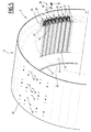
- the rotating electric machine 1 shown on the figure 1 comprises a rotor 3 and a stator 5 surrounding the rotor 3.
- the stator occupies the center of the machine, the rotor surrounding the stator.
- the rotating electrical machine may be synchronous or asynchronous type.
- the rotor 3 may be a package of magnetic sheets or comprise a plurality of copper bars, in the case of an asynchronous machine.
- the rotor 3 may comprise a plurality of wound poles, or a plurality of permanent magnets.
- the machine is a synchronous machine, the rotor 3 of which has a plurality of poles 7 each equipped with permanent magnets 9.
- the rotor 3 is rotatably mounted in the stator 5 around its central axis X.
- the stator 5 then has a generally cylindrical shape, of central axis X. It is delimited radially inwards by a cylindrical inner face 11.
- the rotor 3 is delimited radially outwards by a substantially cylindrical outer face 13 on which The diameter of the internal face 11 of the stator is very slightly greater than the diameter of the outer face 13 of the rotor, so that a thin air gap 15 separates the faces 11 and 13, one of the other.
- the stator 5 comprises a carcass 17, a plurality of axial teeth 19,20 distributed around the central axis X, and a plurality of concentric coils 21, each wound around a tooth 19,20 which is specific thereto.
- the carcass 17 comprises a cylindrical shell 23 of central axis X, and a first annular bottom 25 substantially perpendicular to the axis X (see Figures 5 to 7 ).
- the annular bottom 25 is integral with an axial end of the ferrule 23 and centered on the axis X. It delimits internally a circular opening 27.
- the teeth 19,20 each have an axially elongate shape.
- the teeth 19, 20 are distributed circumferentially about the central axis X, and define between them axial notches 28 for receiving the coils 21.
- the notches 28 are elongated parallel to the axis X and are also distributed around the X central axis. They are closed radially outwardly, that is to say towards the carcass 17, and are open radially inwards. They open into the gap 15.
- the teeth 19, 20 of the two types are placed radially towards the inside of the carcass 17.
- the stator teeth are placed radially towards the outside of the carcass.
- the stator 5 further comprises a removable attachment 29, 31 of each tooth 19, 20 to the carcass 17, and more precisely to the radially inner face 33 of the ferrule 23.
- the attachment 29 of the teeth 19 is different from the attachment 31 of the teeth 20, as explained below, the teeth 19 and 20 being therefore of two different types.
- the teeth 19 and 20 of the two types alternate circumferentially around the axis X.
- each tooth 19, 20 comprises a base 35 pressed against the inner face 33 of the ferrule, a central core 37 around which is wound the corresponding winding 21, and an end 39.
- the core 37 is oriented substantially radially.
- the base 35 is integral with a radially outer end of the core 37, the end 39 being formed on a radially inner side of the core 37.
- the end 39 projects circumferentially on either side of the core 37. 37 and partially closes the notches 28 flanking the tooth.
- Fixing 29 of each tooth 19 of the first type comprises a plurality of screws 41, and a plurality of pins 43, as visible on the figure 3 .
- the attachment 29 comprises for each tooth three screws 41 and four pins 43, distributed axially along the length of the tooth.
- said ferrule comprises orifices 44, 45 for the passage respectively of the screws 41 and the pins 43, the tooth having blind holes 47, 49 placed in correspondence with the orifices 44, 45.
- the screws 41 are engaged from the outside of the carcass, in a radial direction through the orifices 44 and are screwed into the threaded blind holes 47.
- the pins 43 are forced into the orifices 45 and in the blind holes 49, from the outside of the carcass and in a radial direction.
- each lateral surface 55 is slightly inclined with respect to the radial direction. Specifically, when following the surface 55 from the face 53 to the face 51, the surface 55 deviates from the radial direction outwardly of the tooth, that is to say towards the adjacent tooth.
- the surface 55 forms with the radial direction an angle of between 2 and 10 °, for example between 3 and 7 °, and is typically 5 °.
- a tooth 20 of the second type is partially illustrated on the figure 4 .
- each tooth 20 is surrounded by two teeth 19 and vice versa each tooth 19 is surrounded by two teeth 20.
- Each tooth 20 is in contact by the lateral surfaces 56 of its base 35 with the surfaces 55 of the bases 35 of the two 19 teeth that frame it.
- the lateral surfaces 56 of each tooth 20 have complementary orientations of the lateral surfaces 55 of the teeth 19. More precisely, as visible on the figure 4 , each of the two lateral surfaces 56 of the base of the tooth 20 is inclined relative to the radial direction, but this inclination is opposite to that of the surface 55 of the teeth 19.
- each tooth 20 to the carcass is constituted by the lateral surfaces 55 of the two teeth 19 which surround it.
- the teeth 19 are biased radially against the carcass 17 by the screws 41 and the pins 43. This bias is transmitted to the teeth 20 via the outgoing side faces 55 of the teeth 19 bearing against the reentrant side surfaces 56
- the outgoing lateral surfaces 55 of the teeth 19 thus constitute shims which urge the reentrant lateral surfaces 56 of the teeth 20 radially outwards against the carcass 17.
- the manufacturing and mounting tolerances of the various elements of the stator, the materials constituting these elements, the orientation of the surfaces 55, the tightening torque of the screws 47, are chosen so that the teeth 20 are firmly held in the screw position.
- the force applied by the outgoing lateral surfaces 55 is dimensioned so that the teeth 20 are fixed to the carcass and remain in place taking into account the forces experienced by the tooth 20.
- the stator 5 comprises an electrically insulating coating 57 on all the surfaces delimiting each notch 28.
- Each coil 21 is of concentric type, that is to say is wound around a single tooth.
- Each winding 21 typically comprises a conductor 59, wound around the core 37 of the corresponding tooth ( figure 4 ).
- the conductor 59 thus has a plurality of rectilinear portions 61 arranged in the two notches flanking the corresponding tooth, and several portions protruding axially on either side of the tooth.
- the rectilinear portions 61 are for example arranged in each of the notches in one or more layers, for example two layers as illustrated in FIG. figure 4 , three layers or more than three layers.
- the conductor 59 has a plurality of copper wires 64 housed inside a circumferential sheath 65, electrically insulating.
- the coil 21 is of the type without nesting with the other windings. This means that the conductor 59 at the bent portions protruding axially from the tooth, does not intersect or is nested with the conductor of another winding.
- Each winding 21 is electrically connected with other windings via connections, so as to form several phases. However, these connections are made outside the notches, in easily accessible locations to perform the maintenance of the stator.
- the number of stator teeth is close to the number of rotor poles, especially in the case of a three-phase machine. This promotes a more efficient concentration of the magnetic flux passing through the stator windings. Furthermore, the number of notches 28 per rotor pole and per stator phase is less than one, preferably less than 0.5.
- the step of disconnecting the winding of the defective tooth is typically done by isolating the winding of the defective tooth from the other windings. Connections are usually brazed, bolted, or any other suitable type.
- the step of releasing the fixation of the defective tooth is performed differently depending on the type of the defective tooth. If the tooth is fixed to the carcass by screws and pins, the screws are unscrewed from the outside of the carcass, and the pins are extracted from the blind housings 49 and the orifices 45, using a suitable tool .
- the fasteners of the adjacent teeth 19 are partially released so as to reduce the stress exerted by the outgoing side faces on the defective tooth 20.
- the screws 41 for fixing the neighboring teeth are partially unscrewed.
- the pins 43 for fixing the neighboring teeth are partially extracted from their blind housing 49.
- the defective tooth is extracted in an axial movement, in a direction opposite to the annular bottom. extract the tooth from the stator to completely clear the defective tooth from the interval delimited by the two teeth that surround it. By the same movement, the tooth is out of the internal volume of the carcass 17. The extraction of the tooth out of the gap is in an exclusively axial translation movement, without radial component and without rotation.
- the introduction of the new tooth provided with its winding 21 is performed in a movement exactly opposite to the extraction movement of the defective tooth.
- Fixing the new tooth to the carcass is performed by tightening the fixing screws 41 and forcibly engaging the studs 43 of the fastener associated with said tooth when the tooth is of the first type.
- the fixing is performed by tightening the screws 41 and fully engaging the studs 43 of the fasteners of the two adjacent teeth 19.
- the winding of the new tooth is then connected with another electric winding.
- the rotating electrical machine described above has many advantages.
- the stator comprises a detachable attachment of each tooth to the carcass, the stator being arranged so that each tooth can be extracted from the stator with the corresponding winding in an axial movement, after release of the attachment of said tooth to the carcass and disconnection of the corresponding winding vis-à-vis the other windings, maintenance of the stator is greatly facilitated.
- it is particularly simple to replace a faulty tooth. It is not necessary to completely disassemble other stator teeth in order to extract the defective tooth and replace it with another tooth.
- Fixing the teeth by means of screws and pins makes it possible to assemble and disassemble them quickly and easily.
- the attachment of certain teeth to the carcass comprises shims shaped to urge the tooth radially against the carcass makes it easy to fix these teeth, without having to drill holes or holes in the carcass and in the tooth to fix.
- these wedges may be surfaces of the teeth flanking the tooth to be fixed.
- stator teeth is close to the number of rotor poles promotes a more efficient concentration of the magnetic flux passing through the stator windings.
- the number of coils in the stator is less important than on other rotating electrical machines.
- the notches are open at both their axial ends and also radially towards the gap. As a result, the cooling of the coils is effective and the mass of the active part of the electrical machine can be reduced significantly.
- the rotating electrical machine of the invention is particularly suitable for uses at slow rotation speed, for example in a hydraulic electric generator, or a wind turbine in direct or semi-direct attack.
- the rotating electrical machine can have multiple variants.
- the teeth of both types do not necessarily alternate.
- Other arrangements are possible. For example, it is possible to have successively several teeth fixed with the aid of screws and pins, then a tooth fixed by pressure of the neighboring teeth and then again several teeth fixed by screws and pins, etc.
- the removable fasteners of the teeth to the carcass can be of any type.
- all the stator teeth can be fixed using screws and pins.
- the teeth can be fixed only with screws or only with pins.
- the number of screws and the number of pins can be variable and different from the number indicated above.
- Some teeth may be attached directly to the carcass by a connection of the dovetail type, one of the tooth and the carcass bearing a dovetail relief, and the other a groove of complementary shape.
- some teeth may be attached indirectly to the carcass, through other teeth.
- some teeth may be attached to neighboring teeth by dovetail devices, the neighboring teeth being fixed directly to the carcass, for example screws and / or studs.
Landscapes
- Engineering & Computer Science (AREA)
- Power Engineering (AREA)
- Manufacturing & Machinery (AREA)
- Iron Core Of Rotating Electric Machines (AREA)
- Manufacture Of Motors, Generators (AREA)
Applications Claiming Priority (1)
| Application Number | Priority Date | Filing Date | Title |
|---|---|---|---|
| FR1051884A FR2957730B1 (fr) | 2010-03-17 | 2010-03-17 | Machine electrique tournante avec stator a bobinages concentriques |
Publications (2)
| Publication Number | Publication Date |
|---|---|
| EP2367264A1 true EP2367264A1 (de) | 2011-09-21 |
| EP2367264B1 EP2367264B1 (de) | 2019-03-06 |
Family
ID=43413850
Family Applications (1)
| Application Number | Title | Priority Date | Filing Date |
|---|---|---|---|
| EP11305296.3A Active EP2367264B1 (de) | 2010-03-17 | 2011-03-17 | Rotierende elektrische Maschine mit Stator mit konzentrierten Wicklungen |
Country Status (3)
| Country | Link |
|---|---|
| EP (1) | EP2367264B1 (de) |
| ES (1) | ES2728475T3 (de) |
| FR (1) | FR2957730B1 (de) |
Cited By (3)
| Publication number | Priority date | Publication date | Assignee | Title |
|---|---|---|---|---|
| CN104505996A (zh) * | 2014-12-08 | 2015-04-08 | 大唐陕西发电有限公司石泉水力发电厂 | 一种水轮发电机转子检修工艺 |
| FR3024300A1 (fr) * | 2014-07-28 | 2016-01-29 | Lohr Electromecanique | Stator ameliore et machine electrique comportant un tel stator |
| CN109450121A (zh) * | 2018-11-10 | 2019-03-08 | 深圳华引动力科技有限公司 | 铁芯模块、定子铁芯及应用其的开关磁阻电机 |
Families Citing this family (1)
| Publication number | Priority date | Publication date | Assignee | Title |
|---|---|---|---|---|
| CN102916506B (zh) * | 2012-10-26 | 2016-02-10 | 重庆长安汽车股份有限公司 | 一种具有分块式定子的电机 |
Citations (6)
| Publication number | Priority date | Publication date | Assignee | Title |
|---|---|---|---|---|
| EP0627805A2 (de) * | 1993-06-03 | 1994-12-07 | Secretary Of State For Trade And Industry In Her Britannic Majesty's Gov. Of The U.K. Of Great Britain And Northern Ireland | Elektromagnetische Maschine |
| WO2003103114A1 (en) | 2002-05-31 | 2003-12-11 | Politecnico Di Milano | Synchronous electrical concentrated coil machine |
| US20060071574A1 (en) * | 2004-10-04 | 2006-04-06 | Stewart William P | End shields and stators and related methods of assembly |
| FR2883430A1 (fr) * | 2004-12-16 | 2006-09-22 | Gen Electric | Machines et ensembles electriques comprenant un stator sans culasse avec des empilements modulaires de toles. |
| EP2066005A2 (de) * | 2007-11-29 | 2009-06-03 | General Electric Company | Stator und Statorzahnmodule für elektrische Maschinen |
| US20100007236A1 (en) * | 2006-10-20 | 2010-01-14 | Toyota Jidosha Babushiki Kaisha | Stator core and rotating electric machine |
-
2010
- 2010-03-17 FR FR1051884A patent/FR2957730B1/fr active Active
-
2011
- 2011-03-17 EP EP11305296.3A patent/EP2367264B1/de active Active
- 2011-03-17 ES ES11305296T patent/ES2728475T3/es active Active
Patent Citations (6)
| Publication number | Priority date | Publication date | Assignee | Title |
|---|---|---|---|---|
| EP0627805A2 (de) * | 1993-06-03 | 1994-12-07 | Secretary Of State For Trade And Industry In Her Britannic Majesty's Gov. Of The U.K. Of Great Britain And Northern Ireland | Elektromagnetische Maschine |
| WO2003103114A1 (en) | 2002-05-31 | 2003-12-11 | Politecnico Di Milano | Synchronous electrical concentrated coil machine |
| US20060071574A1 (en) * | 2004-10-04 | 2006-04-06 | Stewart William P | End shields and stators and related methods of assembly |
| FR2883430A1 (fr) * | 2004-12-16 | 2006-09-22 | Gen Electric | Machines et ensembles electriques comprenant un stator sans culasse avec des empilements modulaires de toles. |
| US20100007236A1 (en) * | 2006-10-20 | 2010-01-14 | Toyota Jidosha Babushiki Kaisha | Stator core and rotating electric machine |
| EP2066005A2 (de) * | 2007-11-29 | 2009-06-03 | General Electric Company | Stator und Statorzahnmodule für elektrische Maschinen |
Cited By (9)
| Publication number | Priority date | Publication date | Assignee | Title |
|---|---|---|---|---|
| FR3024300A1 (fr) * | 2014-07-28 | 2016-01-29 | Lohr Electromecanique | Stator ameliore et machine electrique comportant un tel stator |
| WO2016016558A3 (fr) * | 2014-07-28 | 2016-06-02 | Lohr Electromecanique | Stator ameliore et machine électrique comportant un tel stator |
| CN106575889A (zh) * | 2014-07-28 | 2017-04-19 | 罗尔机电公司 | 改进的定子,以及包括这种定子的电机 |
| AU2015295145B2 (en) * | 2014-07-28 | 2018-10-25 | Lohr Electromecanique | Improved stator, and electrical machine comprising such a stator |
| CN106575889B (zh) * | 2014-07-28 | 2019-02-22 | 罗尔机电公司 | 改进的定子,以及包括这种定子的电机 |
| US10284031B2 (en) | 2014-07-28 | 2019-05-07 | Lohr Electromecanique | Stator, and electrical machine comprising such a stator |
| CN104505996A (zh) * | 2014-12-08 | 2015-04-08 | 大唐陕西发电有限公司石泉水力发电厂 | 一种水轮发电机转子检修工艺 |
| CN109450121A (zh) * | 2018-11-10 | 2019-03-08 | 深圳华引动力科技有限公司 | 铁芯模块、定子铁芯及应用其的开关磁阻电机 |
| CN109450121B (zh) * | 2018-11-10 | 2024-05-10 | 深圳华引动力科技有限公司 | 铁芯模块、定子铁芯及应用其的开关磁阻电机 |
Also Published As
| Publication number | Publication date |
|---|---|
| EP2367264B1 (de) | 2019-03-06 |
| FR2957730B1 (fr) | 2013-02-22 |
| FR2957730A1 (fr) | 2011-09-23 |
| ES2728475T3 (es) | 2019-10-24 |
Similar Documents
| Publication | Publication Date | Title |
|---|---|---|
| FR2967314A1 (fr) | Machine electrique rotative a entrefers magnetiques multiples | |
| FR3046888A1 (fr) | Stator pour machine electromagnetique a flux axial avec des portions unitaires formant une couronne du stator | |
| WO2013175117A1 (fr) | Rotor de machine electrique et dispositif de maintien d'aimants permanents associe | |
| EP1152516B1 (de) | Elektrische rotierende Maschine mit Flusskonzentrationsrotor und um Zähne gewickelter Stator | |
| EP2367264B1 (de) | Rotierende elektrische Maschine mit Stator mit konzentrierten Wicklungen | |
| WO2010026157A2 (fr) | Flasque connecteur pour machine électrique à enroulements statoriques | |
| FR2823614A1 (fr) | Machine tournante electrique comportant un stator forme de secteurs assembles | |
| EP2625770B1 (de) | Rotor mit zusätzlichen polschuhen für die magneten und elektrische drehmaschine | |
| WO2013136021A2 (fr) | Ensemble de flasques de rotor de machine electrique tournante comportant des pales axiales de ventilation favorisant un flux d'air axial a l'interieur du rotor et rotor de machine electrique associe | |
| FR2931317A1 (fr) | Rotor d'une machine electrique synchrone multipolaire a poles saillants | |
| EP3776814B1 (de) | Gewickelter rotor für eine elektrische synchronmaschine | |
| WO2021123539A1 (fr) | Rotor de machine électrique tournante | |
| FR3082373A1 (fr) | Stator de machine electrique tournante | |
| FR3071370B1 (fr) | Isthmes de ponts magnetiques d'un rotor de machine electrique | |
| FR2645685A1 (fr) | Enroulements bobines sur gabarit, a etages multiples pour moteur a reluctance commutee | |
| WO2020094574A1 (fr) | Rotor a cage d'ecureuil et machine electrique asynchrone comprotant un tel rotor | |
| EP0789442B1 (de) | Fahrzeuggetriebe versehen mit einem elektrischen Retarder | |
| WO2016009141A1 (fr) | Ensemble stator multi-secteurs pour moteur à rotor extérieur | |
| EP0789443A1 (de) | Fahrzeuggetriebe versehen mit einem elektrischen Retarder | |
| FR3057411A1 (fr) | Rotor segmente pour machine asynchrone et machine asynchrone comportant un tel rotor segmente | |
| EP3576258B1 (de) | Welle für elektrisch umlaufende maschine, rotor und herstellungsverfahren eines solchen rotors | |
| EP0789444B1 (de) | Kraftfahrzeuggetriebe, versehen mit einem elektrischen Retarder | |
| EP3304698B1 (de) | Rotierende elektrische maschine mit einem gekühlten genuteten stator, insbesondere einem elektromotor | |
| FR2535542A1 (fr) | Rotor perfectionne pour machine electrique tournante inversee (interne-externe), procede pour sa fabrication et machine electrique incorporant le rotor | |
| FR3074375A1 (fr) | Rotor cylindrique a champ radial, et machine electrique et/ou magnetique comprenant un tel rotor |
Legal Events
| Date | Code | Title | Description |
|---|---|---|---|
| PUAI | Public reference made under article 153(3) epc to a published international application that has entered the european phase |
Free format text: ORIGINAL CODE: 0009012 |
|
| AK | Designated contracting states |
Kind code of ref document: A1 Designated state(s): AL AT BE BG CH CY CZ DE DK EE ES FI FR GB GR HR HU IE IS IT LI LT LU LV MC MK MT NL NO PL PT RO RS SE SI SK SM TR |
|
| AX | Request for extension of the european patent |
Extension state: BA ME |
|
| 17P | Request for examination filed |
Effective date: 20120222 |
|
| RAP1 | Party data changed (applicant data changed or rights of an application transferred) |
Owner name: GE ENERGY POWER CONVERSION TECHNOLOGY LIMITED |
|
| STAA | Information on the status of an ep patent application or granted ep patent |
Free format text: STATUS: EXAMINATION IS IN PROGRESS |
|
| 17Q | First examination report despatched |
Effective date: 20170717 |
|
| GRAP | Despatch of communication of intention to grant a patent |
Free format text: ORIGINAL CODE: EPIDOSNIGR1 |
|
| STAA | Information on the status of an ep patent application or granted ep patent |
Free format text: STATUS: GRANT OF PATENT IS INTENDED |
|
| INTG | Intention to grant announced |
Effective date: 20180928 |
|
| GRAS | Grant fee paid |
Free format text: ORIGINAL CODE: EPIDOSNIGR3 |
|
| GRAA | (expected) grant |
Free format text: ORIGINAL CODE: 0009210 |
|
| STAA | Information on the status of an ep patent application or granted ep patent |
Free format text: STATUS: THE PATENT HAS BEEN GRANTED |
|
| AK | Designated contracting states |
Kind code of ref document: B1 Designated state(s): AL AT BE BG CH CY CZ DE DK EE ES FI FR GB GR HR HU IE IS IT LI LT LU LV MC MK MT NL NO PL PT RO RS SE SI SK SM TR |
|
| REG | Reference to a national code |
Ref country code: GB Ref legal event code: FG4D Free format text: NOT ENGLISH |
|
| REG | Reference to a national code |
Ref country code: CH Ref legal event code: EP Ref country code: AT Ref legal event code: REF Ref document number: 1105866 Country of ref document: AT Kind code of ref document: T Effective date: 20190315 |
|
| REG | Reference to a national code |
Ref country code: DE Ref legal event code: R096 Ref document number: 602011056831 Country of ref document: DE |
|
| REG | Reference to a national code |
Ref country code: IE Ref legal event code: FG4D Free format text: LANGUAGE OF EP DOCUMENT: FRENCH |
|
| REG | Reference to a national code |
Ref country code: NL Ref legal event code: MP Effective date: 20190306 |
|
| REG | Reference to a national code |
Ref country code: LT Ref legal event code: MG4D |
|
| PG25 | Lapsed in a contracting state [announced via postgrant information from national office to epo] |
Ref country code: FI Free format text: LAPSE BECAUSE OF FAILURE TO SUBMIT A TRANSLATION OF THE DESCRIPTION OR TO PAY THE FEE WITHIN THE PRESCRIBED TIME-LIMIT Effective date: 20190306 Ref country code: NO Free format text: LAPSE BECAUSE OF FAILURE TO SUBMIT A TRANSLATION OF THE DESCRIPTION OR TO PAY THE FEE WITHIN THE PRESCRIBED TIME-LIMIT Effective date: 20190606 Ref country code: LT Free format text: LAPSE BECAUSE OF FAILURE TO SUBMIT A TRANSLATION OF THE DESCRIPTION OR TO PAY THE FEE WITHIN THE PRESCRIBED TIME-LIMIT Effective date: 20190306 Ref country code: SE Free format text: LAPSE BECAUSE OF FAILURE TO SUBMIT A TRANSLATION OF THE DESCRIPTION OR TO PAY THE FEE WITHIN THE PRESCRIBED TIME-LIMIT Effective date: 20190306 |
|
| PG25 | Lapsed in a contracting state [announced via postgrant information from national office to epo] |
Ref country code: LV Free format text: LAPSE BECAUSE OF FAILURE TO SUBMIT A TRANSLATION OF THE DESCRIPTION OR TO PAY THE FEE WITHIN THE PRESCRIBED TIME-LIMIT Effective date: 20190306 Ref country code: NL Free format text: LAPSE BECAUSE OF FAILURE TO SUBMIT A TRANSLATION OF THE DESCRIPTION OR TO PAY THE FEE WITHIN THE PRESCRIBED TIME-LIMIT Effective date: 20190306 Ref country code: RS Free format text: LAPSE BECAUSE OF FAILURE TO SUBMIT A TRANSLATION OF THE DESCRIPTION OR TO PAY THE FEE WITHIN THE PRESCRIBED TIME-LIMIT Effective date: 20190306 Ref country code: BG Free format text: LAPSE BECAUSE OF FAILURE TO SUBMIT A TRANSLATION OF THE DESCRIPTION OR TO PAY THE FEE WITHIN THE PRESCRIBED TIME-LIMIT Effective date: 20190606 Ref country code: GR Free format text: LAPSE BECAUSE OF FAILURE TO SUBMIT A TRANSLATION OF THE DESCRIPTION OR TO PAY THE FEE WITHIN THE PRESCRIBED TIME-LIMIT Effective date: 20190607 Ref country code: HR Free format text: LAPSE BECAUSE OF FAILURE TO SUBMIT A TRANSLATION OF THE DESCRIPTION OR TO PAY THE FEE WITHIN THE PRESCRIBED TIME-LIMIT Effective date: 20190306 |
|
| REG | Reference to a national code |
Ref country code: AT Ref legal event code: MK05 Ref document number: 1105866 Country of ref document: AT Kind code of ref document: T Effective date: 20190306 |
|
| REG | Reference to a national code |
Ref country code: ES Ref legal event code: FG2A Ref document number: 2728475 Country of ref document: ES Kind code of ref document: T3 Effective date: 20191024 |
|
| PG25 | Lapsed in a contracting state [announced via postgrant information from national office to epo] |
Ref country code: EE Free format text: LAPSE BECAUSE OF FAILURE TO SUBMIT A TRANSLATION OF THE DESCRIPTION OR TO PAY THE FEE WITHIN THE PRESCRIBED TIME-LIMIT Effective date: 20190306 Ref country code: AL Free format text: LAPSE BECAUSE OF FAILURE TO SUBMIT A TRANSLATION OF THE DESCRIPTION OR TO PAY THE FEE WITHIN THE PRESCRIBED TIME-LIMIT Effective date: 20190306 Ref country code: SK Free format text: LAPSE BECAUSE OF FAILURE TO SUBMIT A TRANSLATION OF THE DESCRIPTION OR TO PAY THE FEE WITHIN THE PRESCRIBED TIME-LIMIT Effective date: 20190306 Ref country code: PT Free format text: LAPSE BECAUSE OF FAILURE TO SUBMIT A TRANSLATION OF THE DESCRIPTION OR TO PAY THE FEE WITHIN THE PRESCRIBED TIME-LIMIT Effective date: 20190706 Ref country code: CZ Free format text: LAPSE BECAUSE OF FAILURE TO SUBMIT A TRANSLATION OF THE DESCRIPTION OR TO PAY THE FEE WITHIN THE PRESCRIBED TIME-LIMIT Effective date: 20190306 Ref country code: IT Free format text: LAPSE BECAUSE OF FAILURE TO SUBMIT A TRANSLATION OF THE DESCRIPTION OR TO PAY THE FEE WITHIN THE PRESCRIBED TIME-LIMIT Effective date: 20190306 Ref country code: RO Free format text: LAPSE BECAUSE OF FAILURE TO SUBMIT A TRANSLATION OF THE DESCRIPTION OR TO PAY THE FEE WITHIN THE PRESCRIBED TIME-LIMIT Effective date: 20190306 |
|
| REG | Reference to a national code |
Ref country code: CH Ref legal event code: PL |
|
| PG25 | Lapsed in a contracting state [announced via postgrant information from national office to epo] |
Ref country code: SM Free format text: LAPSE BECAUSE OF FAILURE TO SUBMIT A TRANSLATION OF THE DESCRIPTION OR TO PAY THE FEE WITHIN THE PRESCRIBED TIME-LIMIT Effective date: 20190306 Ref country code: LU Free format text: LAPSE BECAUSE OF NON-PAYMENT OF DUE FEES Effective date: 20190317 Ref country code: PL Free format text: LAPSE BECAUSE OF FAILURE TO SUBMIT A TRANSLATION OF THE DESCRIPTION OR TO PAY THE FEE WITHIN THE PRESCRIBED TIME-LIMIT Effective date: 20190306 |
|
| REG | Reference to a national code |
Ref country code: BE Ref legal event code: MM Effective date: 20190331 |
|
| REG | Reference to a national code |
Ref country code: DE Ref legal event code: R097 Ref document number: 602011056831 Country of ref document: DE |
|
| PG25 | Lapsed in a contracting state [announced via postgrant information from national office to epo] |
Ref country code: IS Free format text: LAPSE BECAUSE OF FAILURE TO SUBMIT A TRANSLATION OF THE DESCRIPTION OR TO PAY THE FEE WITHIN THE PRESCRIBED TIME-LIMIT Effective date: 20190706 Ref country code: AT Free format text: LAPSE BECAUSE OF FAILURE TO SUBMIT A TRANSLATION OF THE DESCRIPTION OR TO PAY THE FEE WITHIN THE PRESCRIBED TIME-LIMIT Effective date: 20190306 |
|
| PLBE | No opposition filed within time limit |
Free format text: ORIGINAL CODE: 0009261 |
|
| STAA | Information on the status of an ep patent application or granted ep patent |
Free format text: STATUS: NO OPPOSITION FILED WITHIN TIME LIMIT |
|
| PG25 | Lapsed in a contracting state [announced via postgrant information from national office to epo] |
Ref country code: CH Free format text: LAPSE BECAUSE OF NON-PAYMENT OF DUE FEES Effective date: 20190331 Ref country code: LI Free format text: LAPSE BECAUSE OF NON-PAYMENT OF DUE FEES Effective date: 20190331 Ref country code: IE Free format text: LAPSE BECAUSE OF NON-PAYMENT OF DUE FEES Effective date: 20190317 Ref country code: DK Free format text: LAPSE BECAUSE OF FAILURE TO SUBMIT A TRANSLATION OF THE DESCRIPTION OR TO PAY THE FEE WITHIN THE PRESCRIBED TIME-LIMIT Effective date: 20190306 Ref country code: MC Free format text: LAPSE BECAUSE OF FAILURE TO SUBMIT A TRANSLATION OF THE DESCRIPTION OR TO PAY THE FEE WITHIN THE PRESCRIBED TIME-LIMIT Effective date: 20190306 |
|
| 26N | No opposition filed |
Effective date: 20191209 |
|
| PG25 | Lapsed in a contracting state [announced via postgrant information from national office to epo] |
Ref country code: BE Free format text: LAPSE BECAUSE OF NON-PAYMENT OF DUE FEES Effective date: 20190331 Ref country code: SI Free format text: LAPSE BECAUSE OF FAILURE TO SUBMIT A TRANSLATION OF THE DESCRIPTION OR TO PAY THE FEE WITHIN THE PRESCRIBED TIME-LIMIT Effective date: 20190306 |
|
| PG25 | Lapsed in a contracting state [announced via postgrant information from national office to epo] |
Ref country code: TR Free format text: LAPSE BECAUSE OF FAILURE TO SUBMIT A TRANSLATION OF THE DESCRIPTION OR TO PAY THE FEE WITHIN THE PRESCRIBED TIME-LIMIT Effective date: 20190306 |
|
| PG25 | Lapsed in a contracting state [announced via postgrant information from national office to epo] |
Ref country code: MT Free format text: LAPSE BECAUSE OF FAILURE TO SUBMIT A TRANSLATION OF THE DESCRIPTION OR TO PAY THE FEE WITHIN THE PRESCRIBED TIME-LIMIT Effective date: 20190306 Ref country code: FR Free format text: LAPSE BECAUSE OF NON-PAYMENT OF DUE FEES Effective date: 20190506 |
|
| PG25 | Lapsed in a contracting state [announced via postgrant information from national office to epo] |
Ref country code: CY Free format text: LAPSE BECAUSE OF FAILURE TO SUBMIT A TRANSLATION OF THE DESCRIPTION OR TO PAY THE FEE WITHIN THE PRESCRIBED TIME-LIMIT Effective date: 20190306 |
|
| PG25 | Lapsed in a contracting state [announced via postgrant information from national office to epo] |
Ref country code: HU Free format text: LAPSE BECAUSE OF FAILURE TO SUBMIT A TRANSLATION OF THE DESCRIPTION OR TO PAY THE FEE WITHIN THE PRESCRIBED TIME-LIMIT; INVALID AB INITIO Effective date: 20110317 |
|
| PG25 | Lapsed in a contracting state [announced via postgrant information from national office to epo] |
Ref country code: MK Free format text: LAPSE BECAUSE OF FAILURE TO SUBMIT A TRANSLATION OF THE DESCRIPTION OR TO PAY THE FEE WITHIN THE PRESCRIBED TIME-LIMIT Effective date: 20190306 |
|
| PGFP | Annual fee paid to national office [announced via postgrant information from national office to epo] |
Ref country code: DE Payment date: 20240220 Year of fee payment: 14 Ref country code: GB Payment date: 20240220 Year of fee payment: 14 |
|
| PGFP | Annual fee paid to national office [announced via postgrant information from national office to epo] |
Ref country code: ES Payment date: 20240402 Year of fee payment: 14 |