EP2366960B1 - Method and systems for integrating sound attenuation into a filter bank - Google Patents
Method and systems for integrating sound attenuation into a filter bank Download PDFInfo
- Publication number
- EP2366960B1 EP2366960B1 EP11250024.4A EP11250024A EP2366960B1 EP 2366960 B1 EP2366960 B1 EP 2366960B1 EP 11250024 A EP11250024 A EP 11250024A EP 2366960 B1 EP2366960 B1 EP 2366960B1
- Authority
- EP
- European Patent Office
- Prior art keywords
- layers
- attenuating
- air
- filtering layer
- attenuating layers
- Prior art date
- Legal status (The legal status is an assumption and is not a legal conclusion. Google has not performed a legal analysis and makes no representation as to the accuracy of the status listed.)
- Not-in-force
Links
- 238000000034 method Methods 0.000 title claims description 20
- 238000001914 filtration Methods 0.000 claims description 205
- 239000006260 foam Substances 0.000 claims description 42
- 230000008878 coupling Effects 0.000 claims description 27
- 238000010168 coupling process Methods 0.000 claims description 27
- 238000005859 coupling reaction Methods 0.000 claims description 27
- 239000011152 fibreglass Substances 0.000 claims description 22
- 238000011144 upstream manufacturing Methods 0.000 claims description 19
- 238000007599 discharging Methods 0.000 claims 2
- 230000001154 acute effect Effects 0.000 description 20
- 238000009413 insulation Methods 0.000 description 14
- 239000000463 material Substances 0.000 description 7
- 238000001816 cooling Methods 0.000 description 6
- 230000001419 dependent effect Effects 0.000 description 6
- 239000012774 insulation material Substances 0.000 description 6
- 230000008901 benefit Effects 0.000 description 4
- 239000006261 foam material Substances 0.000 description 4
- 238000010521 absorption reaction Methods 0.000 description 3
- 238000010438 heat treatment Methods 0.000 description 3
- 230000007246 mechanism Effects 0.000 description 3
- 238000009423 ventilation Methods 0.000 description 3
- 230000006870 function Effects 0.000 description 2
- 239000007787 solid Substances 0.000 description 2
- 238000010586 diagram Methods 0.000 description 1
- 239000003814 drug Substances 0.000 description 1
- 229940079593 drug Drugs 0.000 description 1
- 230000005484 gravity Effects 0.000 description 1
- 239000012535 impurity Substances 0.000 description 1
- 238000012423 maintenance Methods 0.000 description 1
- 238000005259 measurement Methods 0.000 description 1
- 239000012528 membrane Substances 0.000 description 1
- 230000015654 memory Effects 0.000 description 1
- 239000002184 metal Substances 0.000 description 1
- 239000011490 mineral wool Substances 0.000 description 1
- 230000007935 neutral effect Effects 0.000 description 1
- 230000008569 process Effects 0.000 description 1
- XLYOFNOQVPJJNP-UHFFFAOYSA-N water Substances O XLYOFNOQVPJJNP-UHFFFAOYSA-N 0.000 description 1
Images









Classifications
-
- F—MECHANICAL ENGINEERING; LIGHTING; HEATING; WEAPONS; BLASTING
- F24—HEATING; RANGES; VENTILATING
- F24F—AIR-CONDITIONING; AIR-HUMIDIFICATION; VENTILATION; USE OF AIR CURRENTS FOR SCREENING
- F24F13/00—Details common to, or for air-conditioning, air-humidification, ventilation or use of air currents for screening
- F24F13/24—Means for preventing or suppressing noise
-
- A—HUMAN NECESSITIES
- A47—FURNITURE; DOMESTIC ARTICLES OR APPLIANCES; COFFEE MILLS; SPICE MILLS; SUCTION CLEANERS IN GENERAL
- A47G—HOUSEHOLD OR TABLE EQUIPMENT
- A47G21/00—Table-ware
- A47G21/18—Drinking straws or the like
- A47G21/186—Details of bendable straws
-
- F—MECHANICAL ENGINEERING; LIGHTING; HEATING; WEAPONS; BLASTING
- F24—HEATING; RANGES; VENTILATING
- F24F—AIR-CONDITIONING; AIR-HUMIDIFICATION; VENTILATION; USE OF AIR CURRENTS FOR SCREENING
- F24F8/00—Treatment, e.g. purification, of air supplied to human living or working spaces otherwise than by heating, cooling, humidifying or drying
- F24F8/10—Treatment, e.g. purification, of air supplied to human living or working spaces otherwise than by heating, cooling, humidifying or drying by separation, e.g. by filtering
-
- F—MECHANICAL ENGINEERING; LIGHTING; HEATING; WEAPONS; BLASTING
- F24—HEATING; RANGES; VENTILATING
- F24F—AIR-CONDITIONING; AIR-HUMIDIFICATION; VENTILATION; USE OF AIR CURRENTS FOR SCREENING
- F24F8/00—Treatment, e.g. purification, of air supplied to human living or working spaces otherwise than by heating, cooling, humidifying or drying
- F24F8/10—Treatment, e.g. purification, of air supplied to human living or working spaces otherwise than by heating, cooling, humidifying or drying by separation, e.g. by filtering
- F24F8/108—Treatment, e.g. purification, of air supplied to human living or working spaces otherwise than by heating, cooling, humidifying or drying by separation, e.g. by filtering using dry filter elements
-
- A—HUMAN NECESSITIES
- A47—FURNITURE; DOMESTIC ARTICLES OR APPLIANCES; COFFEE MILLS; SPICE MILLS; SUCTION CLEANERS IN GENERAL
- A47G—HOUSEHOLD OR TABLE EQUIPMENT
- A47G2400/00—Details not otherwise provided for in A47G19/00-A47G23/16
- A47G2400/02—Hygiene
-
- F—MECHANICAL ENGINEERING; LIGHTING; HEATING; WEAPONS; BLASTING
- F24—HEATING; RANGES; VENTILATING
- F24F—AIR-CONDITIONING; AIR-HUMIDIFICATION; VENTILATION; USE OF AIR CURRENTS FOR SCREENING
- F24F13/00—Details common to, or for air-conditioning, air-humidification, ventilation or use of air currents for screening
- F24F13/24—Means for preventing or suppressing noise
- F24F2013/242—Sound-absorbing material
-
- Y—GENERAL TAGGING OF NEW TECHNOLOGICAL DEVELOPMENTS; GENERAL TAGGING OF CROSS-SECTIONAL TECHNOLOGIES SPANNING OVER SEVERAL SECTIONS OF THE IPC; TECHNICAL SUBJECTS COVERED BY FORMER USPC CROSS-REFERENCE ART COLLECTIONS [XRACs] AND DIGESTS
- Y02—TECHNOLOGIES OR APPLICATIONS FOR MITIGATION OR ADAPTATION AGAINST CLIMATE CHANGE
- Y02A—TECHNOLOGIES FOR ADAPTATION TO CLIMATE CHANGE
- Y02A50/00—TECHNOLOGIES FOR ADAPTATION TO CLIMATE CHANGE in human health protection, e.g. against extreme weather
- Y02A50/20—Air quality improvement or preservation, e.g. vehicle emission control or emission reduction by using catalytic converters
Definitions
- Embodiments relate to air handling units and, more particularly, to methods and systems for air filtering and sound attenuating in an air handling unit.
- Air-handling systems have traditionally been used to condition buildings or rooms (hereinafter referred to as "structures").
- the air-handling system may contain components such as cooling coils, heating coils, filters, humidifiers, fans, sound attenuators, controls, and other devices functioning to at least meet a specified air capacity which may represent all or only a portion of a total air handling requirement of the structure.
- the air-handling system may be manufactured in a factory and brought to the structure to be installed or it may be built on site using the appropriate devices to meet the specified air capacity.
- the air-handling compartment of the air-handling system includes one or more fan inlet cones, fan units and a discharge plenum.
- the fan units include an inlet cone, a fan, a motor, fan frame, and any appurtenance associated with the function of the fan (e.g. dampers, controls, settling means, and associated cabinetry).
- filter banks and sound attenuator banks are positioned upstream from the fan.
- the filter bank is generally spaced apart from the sound attenuator so that maintenance can be performed from within the air handler.
- the space between the filter bank and sound attenuator increases the size of the air handler and may cause an unwanted pressure drop therein.
- an air handler according to claim 13 is provided. Further dependent features are set out in the dependent claims.
- the functional blocks are not necessarily indicative of the division between hardware circuitry.
- one or more of the functional blocks e.g., processors or memories
- the programs may be stand alone programs, may be incorporated as subroutines in an operating system, may be functions in an installed software package, and the like. It should be understood that the various embodiments are not limited to the arrangements and instrumentality shown in the drawings.
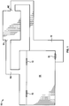
- FIG. 1 illustrates an air handling unit 100.
- the air handling unit 100 includes an air processing system 200 having an inlet 102 and an outlet 104.
- the air handling unit 100 is configured to condition air flowing through a room 106.
- the room 106 includes an inlet plenum 108 and an outlet plenum 110.
- the inlet plenum 108 extends between the room 106 and the outlet 104 of the air handling unit 100.
- the outlet plenum 110 extends from the room 106 to the inlet 102 of the air handling unit 100.
- Vents 112 are positioned at the junction of the inlet plenum 108 and the room 106.
- a return vent 114 is positioned at the junction of the outlet plenum 110 and the room 106.
- filters may be positioned at each junction.
- the inlet plenum 108 and the outlet plenum 110 may include dampers and/or filter banks positioned therein.
- the air is discharged from the vent 112 into the room 106 and circulates there through.
- at least some of the air is channeled through the return vent 114.
- the air flows through the outlet plenum 110 and returns to the air handling unit 100 through inlet 102.
- the air is reconditioned in the air handling unit 100 and re-circulated to the room 106 through inlet plenum 108.
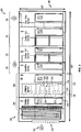
- FIG. 2 illustrates an air processing system 200 that utilizes a fan array air handling system in accordance with an embodiment.
- the system 200 includes an inlet 202 that receives air.
- a heating section 206 that heats the air is included and followed by an air handling section 208.
- a humidifier section 210 is located downstream of the air handling section 208.
- the humidifier section 210 adds and/or removes moisture from the air.
- Cooling coil sections 212 and 214 are located downstream of the humidifier section 210 to cool the air.
- a filter section 216 is located downstream of the cooling coil section 214 to filter the air. The sections may be reordered or removed. Addition sections may be included.
- the air handling section 208 includes an inlet plenum 218 and a discharge plenum 220 that are separated from one another by a bulkhead wall 225 which forms part of a frame 224.
- Fan inlet cones 222 are located proximate to the bulkhead 225 of the frame 224 of the air handling section 208.
- the fan inlet cones 222 may be mounted to the bulkhead wall 225.
- the frame 224 may support the fan inlet cones 222 in a suspended location proximate to, or separated from, the bulkhead wall 225.
- Fans 226 are mounted to drive shafts on individual corresponding motors 228. The motors are mounted on mounting blocks to the frame 224.
- Each fan 226 and the corresponding motor 228 form one of the individual fan units 232 that may be held in separate chambers 230.
- the chambers 230 are shown vertically stacked upon one another in a column.
- more or fewer chambers 230 may be provided in each column.
- One or more columns of chambers 230 may be provided adjacent one another in a single air handling section 208.
- FIG 3 illustrates a top view of the air handling section 208 shown in Figure 1 .
- the air handling section 208 includes an upstream end 234 and a downstream end 236.
- Fans 226 are positioned between the inlet plenum 218 and the discharge plenum 220.
- the inlet plenum 218 is upstream of the fans 226.
- the discharge plenum 220 is downstream of the fans 226.
- a filter bank 238 is positioned at the upstream end 234 of the air handling section 208.
- the filter bank 238 includes a plurality of filters 240 positioned adjacent one another in a row.
- the filters 240 extend within a filter bank housing 241.
- the filters are positioned to form an air tight interface between each filter 240.
- the filters 240 may be formed from foam, pleated paper, spun fiberglass, and/or any other suitable filtering medium.
- the filters 240 are configured to remove impurities from the air flowing through the air handling section 208.
- a plurality of sound attenuation panels 242 are positioned downstream from the filters 240.
- the sound attenuation panels 242 are positioned in a row with channels 244 extending therebetween.
- the sound attenuation panels 242 may have a shape that exhibits a low pressure drop thereacross. Additionally, the sound attenuation panels 242 may be perforated or solid. Additional details regarding the sound attenuation panels 242 are described in more detail below with respect to Figures 28-34 .
- the sound attenuation panels 242 are arranged parallel to the filters 240.
- the filters 240 and sound attenuation panels 242 may be arranged in non-linear and/or non-parallel configurations.
- FIGS 4-25 illustrate various embodiments of filter banks 238 that may be used with the air handling section 208 or in another application. It should be appreciated that the filter banks 238 of the various embodiments may also be utilized with a ceiling unit or any other suitable heating, cooling, or ventilation system.
- the filter banks 238 may be positioned upstream or downstream from the fans 226.
- the filter banks include at least one filtering layer and at least one attenuating layer positioned proximate or immediately adjacent to the filtering layer.
- the filter banks 238 occupy a small space within the air handling section 208 and exhibit a low pressure drop thereacross. It should be noted that the filter banks 238 are illustrated in the air handling section 208.
- the filter banks 238 may be positioned in the inlet plenum 108 and/or the outlet plenum 110 of the air handling unit 100.
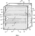
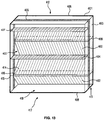
- FIG 4 is a perspective view of a filter/sound attenuation bank housing 301 having outer walls 303.
- the filter/sound attenuation bank housing 301 contains a filter/sound attenuation bank 300. Air flows in the direction 314 through the filter/sound attenuation bank 300.
- a coupling frame 305 extends along the outer walls 303.
- the filter/sound attenuation bank 300 is coupled to the housing 301.
- the filter/sound attenuation bank 300 is coupled to the coupling frame 305.
- the filter/sound attenuation bank 300 includes a plurality of filtering layers 302 and a plurality of attenuating layers 304.
- the filtering layers 302 and the attenuating layers 304 may be coupled to the coupling frame 305 and/or the housing 301.
- the filtering layers 302 extend between adjacent attenuating layers 304.
- the filter/sound attenuation bank 300 includes a top end 306 and a bottom end 308.
- the top end 306 and the bottom end 308 include a filtering layer 302 that extends between an attenuating layer 304 and the housing 301.
- an attenuating layer 304 may be coupled directly to the housing 301.
- the filter/sound attenuation bank 300 is coupled to the housing 301 and/or coupling frame 305 to form an air tight interface.
- the filtering layers 302 and the attenuating layers 304 are coupled together to form an air tight interface. Airflow is directed through the filtering layers 302 of the filter/sound attenuation bank 300.
- the attenuating layers 304 may represent interior walls that are semi-permeable and allow airflow therethrough.
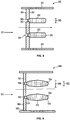
- FIG. 5 is a side view of an embodiment of the filter/sound attenuation bank 300.
- the housing 301 includes planar front and back faces 310 and 312.
- the front and back faces 310 and 312 are perforated to allow air to flow therethrough in the direction of arrows 314.
- the attenuation layers 304 are spaced apart from the outer walls 303.
- the attenuation layers 304 are oriented to extend between the front and back faces 310 and 312.
- the attenuation layers 304 may only extend partially from or to either or both of the front and back faces 310 and 312.
- the filtering layers 302 and the attenuating layers 304 are stacked in an interlaced manner transverse to the direction of air flow 314.
- the attenuating layers 304 may be arranged parallel to each other and substantially parallel to the direction of air flow 314.
- the attenuating layers 304 may be positioned at a common or different acute angles to one another and an acute angle to the air flow 314.
- Each attenuating layer 304 includes opposed ends 316, planar site faces 318 and a middle portion 320 extending therebetween.
- the ends 316 of each attenuating layer 304 may be rounded or convex.
- the ends 316 of the attenuating layers 304 may be flat, pointed, concave, and/or non-uniformly rounded.
- Air channels 322 are formed by adjacent attenuating layers toward the front and back faces 310 and 312.
- the filter layer 302 is oriented to traverse for air flow through the filter/sound attenuation bank 300.
- the air channels 322 are also located between the attenuation layers 304 and outer walls 303 of the housing 301.
- the attenuation layers 304 may represent interior walls that are semi-permeable and form an inner air channel 324 and outer air channels 322. Air flows through the air channels 322, 324 in the direction of 314.
- the air channels 322 and 324 have widths 326, 328 and 330, that may be equal to one another or differ in width.
- the air channels 322, 324 have a common length 332 between parallel planar front and back faces 310 and 312.
- the front and/or back faces 310 and 312 may be contoured to be non-planar such that the length 332 may be different within an individual channel 322, 324 or between different channels 322, 324.
- Each filter layer 302 extends toward the front and back faces 310 and 312.
- the filter layer 302 is oriented to traverse diagonally from an end 316 of a first attenuating layer 304 to an end 316 of an adjacent attenuating layer 304.
- the ends 334 of the filter layers 302 may extend to or from middle portions 320 of the attenuating layers 304.
- the ends 334 may engage and adjoin an end 316 of a first attenuating layer 304 and a middle portion 320 of an adjacent attenuating layer 304.
- the ends 334 of the filter layers 302 abut and form an air tight interface with the ends 316 or middle portions 320 of the attenuating layers 304.
- Figure 6 is a side view of a filter/sound attenuation bank 1000.
- the attenuation layers 1004 extend at least partially from or to either or both of the front and back faces 1010 and 1012.
- the filtering layers 1002 and the attenuating layers 1004 are stacked in an interlaced manner transverse to the direction of air flow 1014.
- the attenuating layers 1004 may be arranged in parallel or at a common or different angle to one another.
- Each attenuating layer 1004 includes opposed ends 1016, planar site faces 1018 and a middle portion 1020 extending therebetween.
- the ends 1016 of each attenuating layer 1004 may be rounded, flat, pointed, convex, concave, and/or non-uniformly rounded.
- the middle portion 1020 has a width 1030 that is greater than a width 1032 of the ends 1016.
- Air channels 1022 are formed by adjacent attenuating layers between the front and back faces 1010 and 1012.
- the air channels 1022 are also located between the attenuation layers 1004 and outer walls 1003 of the housing 1001.
- the attenuation layers 1004 may represent interior walls that are semi-permeable and form an inner air channel 1024 and outer air channels 1022.
- Each filter layer 1002 extends toward the front and back faces 1010 and 1012.
- the filter layer 1002 is oriented to traverse diagonally from an end 1016 of a first attenuating layer 1004 to an end 1016 of an adjacent attenuating layer 1004.
- the ends 1034 of the filter layers 1002 may extend to or from middle portions 1020 of the attenuating layers 1004.
- the ends 1034 engage a coupling mechanism 1035 that couples the filtering layers 1002 to the attenuating layers 1004.
- the coupling mechanism 1035 includes outer clamps 1037 and an inner clamp 1039. The ends 1034 of the filtering layers 1002 engage one of the outer clamps 1037 to form an airtight interface.
- the ends 1016 of the attenuating layer 1004 engage the inner clamp 1039 to form an airtight interface.
- the coupling mechanism 1035 may adjoin an end 1016 of a first attenuating layer 1004 and a middle portion 1020 of an adjacent attenuating layer 1004 to form an airtight interface.
- Figure 7 is a perspective view of a filter/sound attenuation bank housing 351 having outer walls 353, a top wall 356, and a bottom wall 358.
- the filter/sound attenuation bank housing 351 contains a filter/sound attenuation bank 350. Air flows in the direction 357 through the filter/sound attenuation bank 350.
- a coupling frame 355 extends along the outer walls 353.
- the filter/sound attenuation bank 350 is coupled to the housing 351.
- the filter/sound attenuation bank 350 is coupled to the coupling frame 355.
- the filter/sound attenuation bank 350 includes a plurality of filtering layers 352 and a plurality of attenuating layers 354.
- the filtering layers 352 extend between the top wall 356 and the bottom wall 358.
- the filtering layers 352 couple to the walls 356, 358 to form an airtight interface.
- the filtering layers 352 couple to the coupling frame 355.
- the filtering layers 352 are arranged in a row along the same plane.
- the filtering layers 352 are arranged in a non-planar row.
- the attenuating layers 354 extend between adjacent filtering layers 352.
- the attenuating layers 354 may be coupled to the coupling frame 355 and/or the housing 351 to form an airtight interface.
- the attenuating layers 354 may be coupled to the filtering layers 352 to form an airtight interface.
- the attenuating layers 354 extend substantially perpendicularly to the filtering layers 352.
- the attenuating layers 354 may be arranged at a common or different angle from the filtering layers 352. Airflow is directed through the filtering layers 352 of the filter/sound attenuation bank 350.
- the attenuating layers 354 may represent interior walls that are semi-permeable and allow airflow therethrough.
- Figure 8 illustrates a top view of the filter/sound attenuation bank 350.
- the filtering layers are 352 are arranged in the same plane.
- the filtering layers 352 are arranged at angles with respect to one another.
- the filtering layers 352 may be arranged in a concave, convex, and/or curved configuration.
- the filtering layers 352 are arranged so that the ends 362 are positioned adjacent and/or abut one another at the junction 366.
- Filter/sound attenuation bank 350 includes at least one row of filtering layers 352 arranged in parallel and/or at angles to one another.
- the attenuating layers 354 are positioned parallel to one another.
- the attenuating layers 354 may be positioned at angles to one another.
- the attenuating layers 354 extend substantially perpendicular and/or at an angle with respect to the filtering layers 352.
- Each attenuating layer 354 abuts the junction 366 of the filter layer ends 362 and/or the planar face 364 of a filter layer 352.
- the middle portion 372 of each attenuating layer 354 extends in a plane between the ends 370 so that the attenuating layer 354 has a uniform width 385.
- the ends 370 may be rounded, flat, pointed, convex, concave, and/or non-uniformly rounded.
- Airflow is directed through the filtering layers 352 and around the attenuating layers 354.
- the attenuating layers 354 may represent interior walls that are semi-permeable and allow airflow therethrough.
- FIG 9 illustrates a top view of a filter/sound attenuation bank 1150.
- Air flows in a direction 1157 through the filter/sound attenuation bank 1150.
- Each filtering layer 1152 has a pair of ends 1162 and planar faces 1164 extending therebetween.
- the filtering layers are 1152 are arranged in the same plane.
- the filtering layers 1152 are arranged at angles with respect to one another.
- the filtering layers 1152 may be arranged in a concave, convex, and/or curved configuration.
- the filtering layers 1152 are arranged so that the ends 1162 are positioned adjacent one another.
- the filtering layers 1152 are arranged so that the ends 1162 abut each other at a junction 1166 to form an airtight interface.
- Figure 9 illustrates a single row of filtering layers 1152.
- filter/sound attenuation bank 1150 may include multiple rows of filtering layers 1152 arranged in parallel and/or at angles to one another.
- the attenuating layers 1154 are positioned parallel to one another.
- the attenuating layers 1154 may be positioned at angles to one another.
- the attenuating layers 1154 extend substantially perpendicular to the filtering layers 1152.
- the attenuating layers 1154 may extend at angles with respect to the filtering layers 1152.
- Each attenuating layer 1154 abuts a junction 1166 of the filter layer ends 1162 to form an airtight interface.
- the attenuating layers 1154 may abut the planar face 1164 of a filter layer 1152.
- the attenuating layers 1154 may also be coupled to the junction 1166 and/or planar face 1164 utilizing a coupling device.
- Each attenuating layer 1154 includes a pair of ends 1170 and a middle portion 1172 extending therebetween.
- the middle portion 1172 has a width 1181 that is greater than the width 1183 of the ends 1170.
- the ends 1170 may be rounded, flat, pointed, convex, concave, and/or non-uniformly rounded.
- Airflow is directed through the filtering layers 1152 and around the attenuating layers 1154.
- the attenuating layers 1154 may represent interior walls that are semi-permeable and allow airflow therethrough.
- Figure 10 illustrates a top view of a filter/sound attenuation bank 1250.
- the filtering layers are 1252 are arranged in the same plane.
- the filtering layers 1252 are arranged at angles with respect to one another.
- the filtering layers 1252 may be arranged in a concave, convex, and/or curved configuration.
- the filtering layers 1252 are arranged so that the ends 1262 are positioned adjacent and/or abut one another at the junction 1266.
- Filter/sound attenuation bank 1250 includes at least one row of filtering layers 1252 arranged in parallel and/or at angles to one another.
- the attenuating layers 1254 extend at an angle from the filtering layers 1252.
- Each attenuating layer 1254 includes a first attenuating member 1274 and a second attenuating member 1276.
- the first attenuating member 1274 abuts the junction 1266 of the filter layer ends 1262 and/or the planar face 1264 of a filter layer 1252.
- the second attenuating member 1276 extends at an angle from the second attenuating member 1276.
- the attenuating members 1274, 1276 are angled so as to eliminate a line of sight between adjacent attenuating layers 1254. The angle between the attenuating members 1274, 1276 may be the same for each attenuating layer 1254.
- the angle of each attenuating layer 1254 may vary.
- the filter/sound attenuation bank 1250 may include at least one attenuating layer 1254 that extends perpendicular to the filtering layers 1252.
- the attenuating layers 1254 may have a uniform width and/or widths that vary along the length of the middle portion 1272.
- the ends 1270 may be rounded, flat, pointed, convex, concave, and/or non-uniformly rounded. Airflow is directed through the filtering layers 1252 and around the attenuating layers 1254.
- the attenuating layers 1254 may represent interior walls that are semi-permeable and allow airflow therethrough.
- FIG 11 is a top view of a filter/sound attenuation bank 1350.
- the attenuating member 1354 has a third attenuating member 1378 extending at angle from the second attenuating member 1376.
- the attenuating members 1374, 1376, and 1378 are angled so as to eliminate a line of sight between the attenuating layers 1354.
- Airflow 1357 is directed through the filtering layers 1352 and around the attenuating layers 1354.
- the attenuating layers 1354 may represent interior walls that are semi-permeable and allow airflow therethrough.
- FIG 12 is a top view of a filter/sound attenuation bank 1450.
- the attenuation layers 1454 include attenuating members 1474, 1476, and 1478.
- the attenuating members 1474, 1476, and 1478 are angled to eliminate a line of sight therebetween.
- the attenuating members 1454 may include ends 1470 that are rounded, flat, pointed, convex, concave, and/or non-uniformly rounded.
- the filtering layers 1452 extend between adjacent attenuating layers 1454.
- the filtering layers 1452 may extend at an angle between the attenuating layers 1454.
- the filtering layers 1452 extend perpendicular to each attenuating layer 1454.
- the attenuating layers 1454 and the filtering layers 1452 are coupled together to form an airtight interface.
- Figure 12 illustrates a single filtering layer 1452 extending between each adjacent attenuating layer 1454.
- multiple filtering layers 1452 may extend between each attenuating layer 1454.
- Airflow is directed through the filtering layers 1452 and around the attenuating layers 1454.
- the attenuating layers 1454 may represent interior walls that are semi-permeable and allow airflow therethrough.
- a filter bank may have any combination of the filtering layers and attenuating layers shown in Figures 8-12 .
- Figure 13 is a perspective view of a filter/sound attenuation bank housing 401 having outer walls 403 and planar front and back faces 410 and 412. The front and back faces 410 and 412 are perforated to allow air to flow therethrough in the direction of arrows 414.
- the filter/sound attenuation bank housing 401 contains a filter/sound attenuation bank 400. Air flows in the direction 414 through the filter/sound attenuation bank 400.
- a coupling frame 405 extends along the outer walls 403.
- the filter/sound attenuation bank 400 is coupled to the housing 401.
- the filter/sound attenuation bank 400 is coupled to the coupling frame 405.
- the filter/sound attenuation bank 400 includes a plurality of filtering layers 402 and a plurality of attenuating layers 304.
- the filtering layers 402 and the attenuating layers 404 may be coupled to the coupling frame 405 and/or the housing 401.
- the attenuating layers 404 include a front plurality of attenuating layers 407 and a back plurality of attenuating layers 409. Each attenuating layer 404 includes a front end 415, a back end 414, and a middle 416 extending between the ends 415, 414.
- the front plurality of attenuating layers 407 extend along the front face 410.
- the front plurality of attenuating layers 407 are positioned substantially parallel to one another.
- the front plurality of attenuating layers 407 are angled with respect to one another.
- the front plurality of attenuating layers 407 extend from the front face 410 to approximately a center 411 of the filter bank housing 401.
- the front plurality of attenuating layers 407 extend short of or beyond the center 411.
- the back plurality of attenuating layers 409 extend along the back face 412.
- the back plurality of attenuating layers 409 are positioned substantially parallel to one another.
- the back plurality of attenuating layers 409 are angled with respect to one another.
- the back plurality of attenuating layers 409 extend from the back face 412 to approximately the center 411 of the filter bank housing 401.
- the back plurality of attenuating layers 409 extend short of or beyond the center 411.
- the filtering layers 402 extend between the front plurality of attenuating layers 407 and the back plurality of attenuating layers 409. Each filtering layer 402 extends from a front end 415 of a back attenuating layer 409 and a back end 414 of a front attenuating layer 407.
- the filter/sound attenuation bank 400 includes a top end 406 and a bottom end 408.
- the top end 406 and the bottom end 408 include a filtering layer 402 that extends between an attenuating layer 404 and the housing 401.
- an attenuating layer 404 may be coupled directly to the housing 401.
- the filter/sound attenuation bank 400 is coupled to the housing 401 and/or coupling frame 405 to form an air tight interface.
- the filtering layers 402 and the attenuating layers 404 are coupled together to form an air tight interface. Airflow is directed through the filtering layers 402 of the filter/sound attenuation bank 400.
- the attenuating layers 404 may represent interior walls that are semi-permeable and allow airflow therethrough.
- FIG 14 is a side view of an embodiment of the filter/sound attenuation bank 400.
- the attenuation layers 404 extend between the outer walls 303.
- the attenuation layers 304 are oriented to extend from one of the front face 410 and the back face 412.
- the front plurality of attenuating layers 407 extend at least partially from the front face 410 to the back face 412.
- the back plurality of attenuating layers 409 extend at least partially from the back face 412 to the front face 410.
- the filtering layers 402 and the attenuating layers 404 are stacked in an interlaced manner transverse to the direction of air flow 417.
- the attenuating layers 404 may be arranged parallel to each other and substantially parallel to the direction of air flow 417.
- the attenuating layers 404 may be positioned at a common or different acute angles to one another and an acute angle to the air flow 417.
- the attenuating layer ends 415, 414 may be rounded, flat, pointed, concave, convex, and/or non-uniformly rounded.
- Air channels 422 are formed by adjacent attenuating layers toward the front and back faces 410 and 412.
- the filtering layer 402 is oriented traverse to air flow through the filter/sound attenuation bank 400.
- the air channels 422 are also located between the attenuation layers 404 and outer walls 403 of the housing 401.
- the attenuation layers 404 may represent interior walls that are semi-permeable and form an inner air channel 424 and outer air channels 422. Air flows through the air channels 422, 424 in the direction of 417.
- the air channels 422 and 424 have widths 426, 428 and 430, that may be equal to one another or differ in width.
- the air channels 422, 424 have a common length 432 between parallel planar front and back faces 410 and 412.
- the front and/or back faces 410 and 412 may be contoured to be non-planar such that the length 432 may be different within an individual channel 422, 424 or between different channels 422, 424.
- the filtering layers 402 extend between the front plurality of attenuating layers 407 and the back plurality of attenuating layers 409. Each filtering layer 402 extends from a front end 415 of a back attenuating layer 409 and a back end 414 of a front attenuating layer 407.
- the ends 434 of the filter layers 402 may extend to or from middle portions 420 of the attenuating layers 404.
- the ends 434 may engage and adjoin an end 415, 414 of an attenuating layer 404 and a middle portion 420 of an adjacent attenuating layer 404.
- the ends 434 of the filter layers 402 abut and form an air tight interface with the ends 416 or middle portions 420 of the attenuating layers 404.
- Figure 15 is a side view of a filter/sound attenuation bank 1400.
- the front plurality of attenuating layers 1407 extend at least partially from the front face 1410 to the back face 1412.
- the back plurality of attenuating layers 1409 extend at least partially from the back face 1412 to the front face 1410.
- the filtering layers 1402 and the attenuating layers 1404 are stacked in an interlaced manner.
- An additional plurality of attenuating layers 1405 are arranged between adjacent front attenuating layers 1407 and between adjacent back attenuating layers 1409.
- the attenuating layers 1404 and 1405 may be arranged parallel to each other and substantially parallel to the direction of air flow 1417.
- the attenuating layers 1404 and 1405 may be positioned at a common or different acute angles to one another and an acute angle to the air flow 1417.
- Air channels 1422 are formed by adjacent attenuating layers.
- the attenuation layers 1404 and 1405 may represent interior walls that are semi-permeable and form an inner air channel 1424 and outer air channels 1422. Air flows through the air channels 1422, 1424 in the direction of 1417.
- the filtering layers 1402 extend between the front plurality of attenuating layers 1407 and the back plurality of attenuating layers 1409.
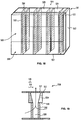
- Figure 16 illustrates a filter/sound attenuation bank housing 451 having a filter/sound attenuation bank 450.
- the housing 451 includes outer walls 453, a top 455, a bottom 457, a front face 459, and a back face 461.
- the front face 459 and at least a portion of the back face 461 are perforated to allow air to flow therethrough in the direction of arrows 456.
- a coupling frame 405 extends along the outer walls 453 and the top 455.
- the filter/sound attenuation bank 450 includes attenuating layers 454 and filtering layers 452.
- the attenuating layers 454 and filtering layers 452 are coupled to the housing 451 and/or the coupling frame 405 to form an airtight interface.
- Attenuating layers 454 extend between the front face 459 and the back face 461.
- the attenuating layers 454 are arranged perpendicular to each of the front face 459 and the back face 461.
- the attenuating layers 454 may extend at an acute angle with respect to the front and back faces 459, 461.
- the attenuating layers 454 are positioned in parallel.
- the attenuating layers 454 may be acutely angled with respect to each other.
- Airflow is directed around attenuating layers 454 and through the filtering layers 452 of the filter/sound attenuation bank 450.
- the attenuating layers 454 may represent interior walls that are semi-permeable and allow airflow therethrough.
- Filtering layers 452 extend at least partially from the back face 461.
- the filtering layers 452 extend substantially perpendicular to the front and back faces 459, 461.
- the filtering layers 452 may extend at an acute angle to front and back faces 459, 461.
- the filtering layers 452 are arranged parallel to one another.
- the filtering layers 452 may be arranged at an angle to one another.
- a pair of filtering layers 452 is positioned within a pair of adjacent attenuating layers 454.
- any number of filtering layers 452 may be positioned between adjacent attenuating layers 454.
- the filtering layers 452 form an inner channel 462 through a perforated portion 464 of the back face 461.
- Figure 17 illustrates a top view of the filter/sound attenuation bank 450.
- Adjacent attenuating layers 454 form an outer channel 466.
- the outer channel 466 has a width 468.
- the attenuating layers 454 form a plurality of outer channels 466 each having the same width 468.
- channels 466 may have varying widths 468.
- the outer channel 466 has a uniform width 468.
- the width 468 of the outer channel 466 may vary.
- the attenuating layers 454 are arranged perpendicular to each of the front face 459 and the back face 461.
- the attenuating layers 454 may extend at an acute angle with respect to the front and back faces 459, 461.
- the attenuating layers 454 are positioned in parallel.
- the attenuating layers 454 may be acutely angled with respect to each other.
- a pair of filtering layers 452 extends from the back face 461.
- the filtering layers 452 extend substantially perpendicular to the front and back faces 459, 461.
- the filtering layers 452 may extend at an acute angle to front and back faces 459, 461.
- the filtering layers 452 may be arranged at any angle with respect to one another.
- the filtering layers 452 extend between a pair of adjacent attenuating layers 454.
- the filtering layers 452 form an inner channel 462 to a perforated portion 464 of the back face 461.
- An attenuating cap 470 extends between the ends 472 of adjacent filtering layers 452.
- the attenuating cap 470 may represent interior wall or a semi-permeable membrane allowing air flow into the inner channel 462.
- the attenuating cap may be rounded, flat, pointed, concave, convex, and/or non-uniformly rounded.
- FIG 18 illustrates a filter/sound attenuation bank housing 501 having a filter/sound attenuation bank 500.
- the housing 501 includes outer walls 503, a top 505, a bottom 507, a front face 509, and a back face 511.
- the front face 509 and at least a portion of the back face 511 are perforated to allow air to flow therethrough in the direction of arrows 504.
- a coupling frame 513 extends along the outer walls 503 and the top 505.
- the filter/sound attenuation bank 500 includes attenuating layers 504 and filtering layers 502.
- the attenuating layers 504 and filtering layers 502 are coupled to the housing 501 and/or the coupling frame 513 to form an airtight interface.
- Attenuating layers 504 extend at least partially between the front face 509 and the back face 511. In the exemplary embodiment, the attenuating layers 504 extend from the back face 511. Optionally, the attenuating layers 504 may extend from the front face 509. The attenuating layers 504 are arranged perpendicular to each of the front face 509 and the back face 511. Optionally, the attenuating layers 504 may extend at an acute angle with respect to the front and back faces 509, 511. The attenuating layers 504 are positioned in parallel. Optionally, the attenuating layers 504 may be acutely angled with respect to each other. Airflow is directed through the filtering layers 502 and through a channel 506 extending through the attenuating layers 504. Optionally, the attenuating layers 504 may represent interior walls that are semi-permeable and allow airflow therethrough. Optionally, the airflow is directed through the channel 506 to the filtering layers 502.
- Filtering layers 502 extend at least partially from the front face 509. Optionally, the filtering layers extend at least partially from the back face 511.
- the filtering layers 502 extend substantially perpendicular to the front and back faces 509, 511.
- the filtering layers 502 may extend at an acute angle to front and back faces 509, 511.
- the filtering layers 502 are arranged parallel to one another.
- the filtering layers 502 may be arranged at an angle to one another.
- Each filtering layer 502 abuts an attenuating layer 504 to form an airtight interface.
- the filtering layers 502 direct airflow into the channel 506.
- Figure 19 illustrates a top view of the filter/sound attenuation bank 500.
- the filtering layers 502 abut the attenuating layers 504 to form the channel 506.
- the attenuating layers 504 and the filtering layers 502 are arranged perpendicular to each of the front face 509 and the back face 511.
- the attenuating layers 504 and filtering layers 502 may extend at an acute angle with respect to the front and back faces 509, 511.
- the attenuating layers 504 and the filtering layers 502 are positioned in parallel.
- the attenuating layers 504 and the filtering layers 502 may be acutely angled with respect to each other.
- the attenuating layers 504 have a front end 510 and a back end 512.
- the front end 510 has a width 514 that is greater than a width 516 of the back end 512.
- the channel 506 expands from the front face 509 to the back face 511.
- the attenuating layers 504 may have a uniform width.
- the attenuating layers may be rounded, flat, pointed, concave, convex, and/or non-uniformly rounded.
- the attenuating layers 504 and the filtering layers 502 form the channel 506.
- the channel 506 directs airflow to a perforated portion 517 of the back face 511.
- Figure 20 illustrates a filter/sound attenuation bank housing 551 having a filter/sound attenuation bank 550.
- the housing 551 includes outer walls 553, a top 555, a bottom 557, a front face 559, and a back face 561.
- the front face 559 and at least a portion of the back face 561 are perforated to allow air to flow therethrough in the direction of arrows 558.
- a coupling frame 563 extends along the outer walls 553 and the top 555.
- the filter/sound attenuation bank 550 includes attenuating layers 554 and filtering layers 552.
- the attenuating layers 554 and filtering layers 552 are coupled to the housing 551.
- the attenuating layers 554 and the filtering layers 552 may be coupled to coupling frame 563 to form an airtight interface.
- Filtering layers 552 extend at least partially between the front face 559 and the back face 561.
- the filtering layers 552 are arranged perpendicular to each of the front face 559 and the back face 561.
- the filtering layers 552 may extend at an acute angle with respect to the front and back faces 559, 561.
- the filtering layers 552 are positioned in parallel.
- the filtering layers 552 may be acutely angled with respect to each other. Airflow is directed through a channel 556 formed between the filtering layers 552 and through each filtering layer 552.
- Attenuating layer 554 extends at least partially from the back face 561.
- the attenuating layer 554 extends at least partially from the front face 559.
- the attenuating layer 554 extends substantially perpendicular to the front and back faces 559, 561.
- the attenuating layer 554 may extend at an acute angle to front and back faces 559, 561.
- the attenuating layer 554 is arranged parallel to the filtering layers 552.
- the attenuating layer 554 may be arranged at an angle with respect to the filtering layer 552.
- the attenuating layer 554 directs airflow through each of the filtering layers 552.
- the attenuating layers 554 may represent interior walls that are semi-permeable and allow airflow therethrough.
- Figure 21 illustrates a top view of the filter/sound attenuation bank 550.
- the filtering layers 552 form the channel 556.
- the attenuating layer 554 and the filtering layers 552 are arranged perpendicular to each of the front face 559 and the back face 561.
- the attenuating layer 554 and filtering layers 552 may extend at an acute angle with respect to the front and back faces 559, 561.
- the attenuating layer 554 and the filtering layers 552 are positioned in parallel.
- the attenuating layer 554 and the filtering layers 552 may be acutely angled with respect to each other.
- the attenuating layer 554 has a front end 560 and a back end 562.
- the back end 562 is coupled to the back face 561 to form an airtight interface.
- the front end 560 is rounded.
- the front end 560 may be flat, pointed, concave, convex, and/or non-uniformly rounded.
- the filtering layers 552 form the channel 556.
- the channel 556 directs airflow to an opening 564 of the back face 561.
- opening 564 may be a perforated portion of the back face 561.
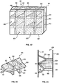
- Figure 22 illustrates a filter/sound attenuation bank housing 601 having a filter/sound attenuation bank 600.
- the housing 601 includes outer walls 603, a top 605, a bottom 607, a front face 609, and a back face 611.
- the front face 609 and at least a portion of the back face 611 are perforated to allow air to flow therethrough in the direction of arrows 606.
- a coupling frame 613 extends along the outer walls 603 and the top 605.
- the filter/sound attenuation bank 600 includes attenuating layers 604 and filtering layers 602.
- the attenuating layers 604 and filtering layers 602 are coupled to the housing 601.
- the attenuating layers 604 and the filtering layers 602 may be coupled to coupling frame 613 to form an airtight interface.
- FIG 23 illustrates a perspective view of the filter/sound attenuation bank 600.
- the filter/sound attenuation bank 600 includes a plurality of filtering layers 602 and a plurality of attenuating layers 604.
- the plurality of filtering layers 602 includes a plurality of upstream filtering layers 608, a plurality of first downstream filtering layers 610, and a plurality of second downstream filtering layers 612.
- Each filtering layer 602 includes an upstream end 614 and a downstream end 616.
- the ends 614 and 616 are flat.
- the ends 614 and 616 may be rounded, concave, convex, pointed, and/or non-uniformly rounded.
- the downstream end 616 of upstream filtering layer 608 is positioned adjacent the upstream end 614 of each of the first and second downstream filtering layers 610 and 612.
- these ends may be coupled and/or formed integrally to form an airtight interface.
- the first downstream filtering layer 610 extends from the upstream filtering layer 608 at an acute angle.
- the second downstream filtering layer 612 extends from the upstream filter layer 608 at an acute angle that is equal and opposite to the angle between the first downstream filtering layer 612 and the upstream filtering layer 608.
- the two angles are not equal.
- the attenuating layers 604 extend between the upstream filtering layer 608 and one of the first downstream filtering layer 610 and the second downstream filtering layer 612.
- the attenuating layers 604 may extend between the first and second downstream attenuating layers 610 and 612.
- the attenuating layers 604 extend substantially perpendicular to the filtering layers 602.
- the attenuating layers 604 may extend at an angle from the filtering layers 602.
- Adjacent attenuating layers 604 form air channels 618.
- the attenuating layers 554 may represent interior walls that are semi-permeable and allow airflow therethrough.
- Figure 24 illustrates a top view of the filter/sound attenuation bank 600.
- the attenuating layer 604 form the channel 618.
- the attenuating layers 604 are arranged parallel to each of the front face 609 and the back face 611.
- the attenuating layers 604 may extend at an acute angle with respect to the front and back faces 609, 611.
- the upstream filtering layer 608 is positioned perpendicular to the front and back face 609, 611.
- the upstream filtering layers are positioned at an acute angle with respect to the front and back faces 609, 611.
- the first downstream filtering layer 610 and the second downstream filtering layer 612 are each positioned at an angle with respect to the front and back face 609, 611.
- the first and second downstream filtering layers 610, 612 may extend parallel to the front and back faces 609, 611.
- the attenuating layer 604 has a front end 620 and a back end 622.
- the back end 622 is coupled to one of the filtering layers 602 to form an airtight interface.
- the front end 620 is rounded.
- the front end 620 may be rounded, flat, pointed, concave, convex, and/or non-uniformly rounded.
- the attenuating layers 604 form the channel 618.
- the channel 618 directs airflow through an opening and/or perforated portion of the back face 611.
- FIG 25 is a perspective view of a damper 700 formed in accordance with an embodiment.
- the back draft damper 700 comprises a shell 705 which defines a central opening 702 having an inlet 701 and an outlet 703 through which air passes.
- the shell 705 is constructed to fit into a duct or passageway through which air flows, or be placed immediately upstream or downstream of a fan unit.
- the size of the shell 705 depends upon the size of the duct, passageway or fan unit.
- the shell 705 is constructed of 16 gauge sheet metal and has a lip located at the outlet 703 which engages an optional egg crate flow straightener 706.
- the shell 705 has a top 708, bottom 709 and sides 710.
- the shell 705 can be rectangular, elliptical, or round.
- the shell 705 can be fabricated from many types of materials and have different dimensions based on a particular application.
- a plurality of vanes 712 extend between the top and bottom surfaces 708, 710 of the shell 705, The vanes 712 move between open positions, where air can flow substantially unimpeded through the central opening 702, and closed positions, dashed line, where air cannot flow through the central opening.
- the vanes 712 have top ends 713 and bottom ends 715, rounded leading edges 714 and sides 716 which converge to thinner trailing edges 718 resulting in a neutral aerodynamic shape which creates little drag due to air flowing over the vanes.
- the vanes 712 have a width which is less than or equal to the depth of the shell 705 and a length which is slightly less than the height of the shell 705.
- the vanes 712 may have any size suitable for use with the shell 705.
- the vanes 712 are configured as a solid attenuating layer.
- the vanes 712 may be semi-permeable and allow airflow there through.
- the vanes 712 may include filtering layers.
- the vanes 712 may be a combination of attenuating layers and filtering layers.
- a filter bank 720 is positioned at the outlet 703.
- the filter bank 720 may be positioned at the inlet 701. The filter bank 720 is coupled to the shell 705 to form an airtight interface.
- the vanes 712 are rotatably mounted in the shell 705 such that their axes of rotation 726 are slightly offset front to back from the vertical at an angle with the tops of the vanes 712 being closer to the inlet 701 than the bottoms of the vanes 712.
- the amount of offset depends on the size and weight of the vanes and the amount of airflow that will pass through the damper.
- the purpose of the offset is to cause gravity to rotate the vanes to their fully closed position when there is no positive airflow through the damper, much in the same manner that a refrigerator door closes.
- the offset should be as little as possible to obtain this result so that the vanes can rotate to their open positions quickly when there is any positive airflow through the shell.
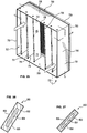
- FIG 26 illustrates an attenuating filter 800 that may be used with the example embodiments above.
- the attenuating filtering includes an attenuating layer 804 and a filtering layer 802.
- the attenuating layer 804 has a front face 806 and a back face 808.
- the attenuating layer 804 is semi-permeable and allows airflow therethrough.
- the filtering layer 802 extends along each side of the attenuating layer 804 to encase the attenuating layer 804 therein.
- the filtering layer 802 extends along only one of the front face 806 and/or the back face 808 of the attenuating layer 804.
- FIG 27 illustrates an attenuating filter 850 that may be used with the example embodiments illustrated above.
- the attenuating filtering includes an attenuating layer 854 and a filtering layer 852.
- the attenuating layer 854 is semi-permeable and allows airflow therethrough.
- the filtering layer 852 has a front face 856 and a back face 858.
- the attenuating layer 854 extends along each side of the filtering layer 852 to encase the filtering layer 852 therein.
- the attenuating layer 854 extends along only one of the front face 856 and/or the back face 858 of the filtering layer 852.
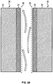
- Figure 28 shows airflow between the two panels 20 which represent acoustically insulted surfaces and sound attenuation layers.
- Figures 28-30 show a first embodiment in which a fiberglass core 22 has an open cell foam 24 layered with at least one side of the fiberglass core 22.
- Figures 28 and 30-33 show a second embodiment combining the use of open cell foam 24 with for use of perforated rigid facing 26.
- Figure 33 and 34 show a third embodiment in which the entire insulation board is replaced with an uncoated open cell foam pad 24.
- this layered embodiment includes a fiberglass core 22 (or other type of insulation) that has an open cell foam 24 layered with at least one side of the fiberglass core 22.
- a fiberglass core 22 or other type of insulation
- an open cell foam 24 layered with at least one side of the fiberglass core 22.
- One advantage to using both the fiberglass material and the open cell foam material is that it is less expensive than using open cell foam material alone because open cell foam more expensive than fiberglass.
- Another advantage to using both the fiberglass material and the open cell foam material is that it weighs less than using fiberglass material alone because fiberglass weighs more than open cell foam.
- Another advantage to using both the fiberglass material and the open cell foam material is that is that the two materials provide different types of acoustic insulation over a different range of frequencies. Together, the two materials provide sound absorption over greater range of frequencies.
- the graph below shown with a vertical axis as the absorption coefficient going from 0 to 1 and a horizontal axis showing the frequency going from 0 to 10,000 Hz at approximately the peak point
- the graph below is meant
- Alternative embodiments of the first layered embodiment include a fiberglass core 22 with one side layered with open cell foam 24 ( Figure 28 ), a fiberglass core 22 with both sides layered with open cell foam 24 ( Figure 29 ), and a fiberglass core 22 and layered with open cell foam 24 secured by perforated rigid facing 26 ( Figure 30 ).
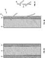
- the bottom section of Figure 33 shows the embodiment of Figure 30 in use in an exemplary air handler.
- an alternative embodiment could include more than two layers of different types of insulation.
- a four layer version could be open cell foam, fiberglass, rockwool, and open cell foam.
- the layered embodiment could actually be "tuned” using different types of insulations, different quantities of insulations, and different thicknesses of insulations to have the desired acoustic properties for the intended use.
- the embodiments described herein include a method for making an air handler using the panels and layers.
- the method includes the steps of providing an air handler system with at least one air handler surface, providing a core of first insulation material having at least one layering surface, and providing a facing of open cell foam second insulation material. Then, the facing is at least partially layered to the at least one layering surface to form a layered insulation board. Finally, the at least one air handler surface is at least partially covered with the layered insulation board so that the facing is exposed to airflow through the air handler.
- this perf-secured embodiment combines the use of open cell foam 24 with for use of perforated rigid facing 26.
- Combining the use of open cell foam and perforated rigid facing provides significant advantages for use in air handlers.
- the use of the perforated rigid facing 26 to secure the open cell foam 24 does not significantly reduce the sound absorption qualities of the open cell foam 24.
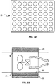
- the open cell structure of the open cell foam 24 allows portions of the open cell foam 24 to protrude from openings defined in the perforated rigid facing 26 (shown in front view in Figure 32 ).
- the exposed open cell foam 24 is able to absorb sound waves.
- protruding open cell foam 24 formed between the openings in the perforated rigid facing 26 absorbs sound waves. This can be compared to prior art embodiments in which sound waves are reflected by the substantially rigid diaphragms formed by the smooth facing being divided by the perforated rigid facing.
- Alternative embodiments of the second perf-secured embodiment include a fiberglass core 22 and layered with open cell foam 24 secured by perforated rigid facing 26 ( Figure 30 ) and non-layered open cell foam 24 secured by perforated rigid facing 26 (the bottom section of Figure 33 ). It should be noted that alternative embodiments may replace perforated rigid facing 26 shown in Figure 32 with alternative securing structure such as perforated rigid facing 26 with alternatively shaped openings, straps, netting, wire grids, or other securing structure suitable to prevent the open cell foam 24 from being drawn inward.
- the embodiments described herein include a method for making an air handler using the perf-secured embodiment.
- the method includes the steps of providing an air handler system with at least one air handler surface, providing open cell foam insulation material, and providing securing structure through which said facing may be exposed. Then, the at least one air handler surface is at least partially covered with the open cell foam insulation material. Finally, the open cell foam insulation material is secured to the at least one air handler surface so that the protruding open cell foam insulation material is exposed to sound waves and/or airflow through the air handler.
- this uncoated embodiment combines the entire insulation board is replaced with uncoated open cell foam 24.
- pharmaceutical companies involved in ingestible or injectable drugs would find it unacceptable to have any fiberglass in the air handler.
- Alternative embodiments of the second uncoated embodiment include uncoated open cell foam 24 secured by perforated rigid facing 26 ( Figure 33 ) uncoated open cell foam 24 secured in a frame 30 ( Figure 34 ).
- FIG 35 is a flowchart of a method 900 for forming an air handling unit 100.
- a fan array is positioned within the air handling unit.
- the fan array is configured to channel air through the air handling unit.
- a filter bank is positioned within the air handling unit to filter the air flowing therethrough.
- the filter bank may be positioned upstream and/or downstream from the fan array.
- Positioning the filter bank includes positioning at least one filtering layer, at 906.
- at least one attenuating layer is positioned adjacent the filtering layer.
- the attenuating layer may abut the filtering layer. Additionally, the attenuating layer may be coupled to the filtering layer.
- the filtering layers and attenuating layers are arranged using at least one of the configurations shown in Figures 4-25 .
- the embodiments described herein are described with respect to an air handling system. It should be noted that the embodiments described may be used within the air handling unit and/or in the inlet or discharge plenum of the air handling system. The embodiments may also be used upstream and/or downstream of the fan array within the air handling unit.
- the described embodiments may be used in a clean room environment. The embodiments may be positioned in the discharged plenum and/or the return chase of the clean room.
- the embodiments may be used in residential HVAC systems.
- the embodiments may be used in the ducts of an HVAC system.
- the embodiments may be used with precision air control systems, DX and chilled-water air handlers, data center cooling systems, process cooling systems, humidification systems, and factory engineered unit controls.
- the embodiments may be used with commercial and/or residential ventilation products.
- the embodiments may be used in the hood and/or inlet of the ventilation product.
- the embodiment may be positioned downstream of the inlet in a duct and/or at a discharge vent.
Landscapes
- Engineering & Computer Science (AREA)
- Chemical & Material Sciences (AREA)
- Combustion & Propulsion (AREA)
- Mechanical Engineering (AREA)
- General Engineering & Computer Science (AREA)
- Filtering Of Dispersed Particles In Gases (AREA)
- Exhaust Silencers (AREA)
- Soundproofing, Sound Blocking, And Sound Damping (AREA)
- Filtering Materials (AREA)
- Air Filters, Heat-Exchange Apparatuses, And Housings Of Air-Conditioning Units (AREA)
Description
- Embodiments relate to air handling units and, more particularly, to methods and systems for air filtering and sound attenuating in an air handling unit.
- Air-handling systems (also referred to as an "air handler") have traditionally been used to condition buildings or rooms (hereinafter referred to as "structures"). The air-handling system may contain components such as cooling coils, heating coils, filters, humidifiers, fans, sound attenuators, controls, and other devices functioning to at least meet a specified air capacity which may represent all or only a portion of a total air handling requirement of the structure. The air-handling system may be manufactured in a factory and brought to the structure to be installed or it may be built on site using the appropriate devices to meet the specified air capacity. The air-handling compartment of the air-handling system includes one or more fan inlet cones, fan units and a discharge plenum. The fan units include an inlet cone, a fan, a motor, fan frame, and any appurtenance associated with the function of the fan (e.g. dampers, controls, settling means, and associated cabinetry).
- In certain applications, filter banks and sound attenuator banks are positioned upstream from the fan. The filter bank is generally spaced apart from the sound attenuator so that maintenance can be performed from within the air handler. The space between the filter bank and sound attenuator increases the size of the air handler and may cause an unwanted pressure drop therein.
- There remains a need for a more compact filter bank and sound attenuator configuration that reduces the pressure drop within the air handler.
- In accordance with the present invention, there is provided a filter bank according to
claim 1.
Further dependent features are set out in the dependent claims. - In another aspect of the invention, an air handler according to claim 13 is provided. Further dependent features are set out in the dependent claims.
- In accordance with a third aspect of the present invention, there is provided a method of flitering and attenuating sound within an air handler according to claim 16. Further dependent features are set out in the dependent claims.
-
-
Figure 1 is a schematic view of an air handling unit in accordance with an embodiment. -
Figure 2 is an air processing system that may be used with the air handling unit shown inFigure 1 . -
Figure 3 is a top view of the fan wall section shown inFigure 2 . -
Figure 4 is a perspective view of an embodiment of a filter/sound attenuation bank formed in accordance with an embodiment. -
Figure 5 is a side view of a filter/sound attenuation bank formed in accordance with an embodiment. -
Figure 6 is a side view of a filter/sound attenuation bank formed in accordance with an embodiment. -
Figure 7 is a perspective view of a filter/sound attenuation bank housing formed in accordance with an embodiment. -
Figure 8 is a top view of a filter/sound attenuation bank formed in accordance with an embodiment. -
Figure 9 is a top view of a filter/sound attenuation bank formed in accordance with an embodiment. -
Figure 10 is a top view of a filter/sound attenuation bank formed in accordance with an embodiment. -
Figure 11 is a top view of a filter/sound attenuation bank formed in accordance with an embodiment. -
Figure 12 is a top view of a filter/sound attenuation bank formed in accordance with an embodiment. -
Figure 13 is a perspective view of a filter/sound attenuation bank housing formed in accordance with an embodiment. -
Figure 14 is a side view of a filter/sound attenuation bank formed in accordance with an embodiment. -
Figure 15 is a side view of a filter/sound attenuation bank formed in accordance with an embodiment. -
Figure 16 is a perspective view of a filter/sound attenuation bank housing formed in accordance with an embodiment. -
Figure 17 is a top view of a filter/sound attenuation bank formed in accordance with an embodiment. -
Figure 18 is a perspective view of a filter/sound attenuation bank formed in accordance with an embodiment. -
Figure 19 is a top view of a filter/sound attenuation bank formed in accordance with an embodiment. -
Figure 20 is a perspective view of a filter/sound attenuation bank formed in accordance with an embodiment. -
Figure 21 is a top view of a filter/sound attenuation bank formed in accordance with an embodiment. -
Figure 22 is a perspective view of a filter/sound attenuation bank housing formed in accordance with an embodiment. -
Figure 23 is a perspective view of a filter/sound attenuation bank formed in accordance with an embodiment. -
Figure 24 is a side view of the filter/sound attenuation bank shown inFigure 22 . -
Figure 25 is a perspective view of a damper formed in accordance with an embodiment. -
Figure 26 is a cross-sectional view of a combined attenuating and filtering layer formed in accordance with an embodiment. -
Figure 27 is a cross-sectional view of another combined attenuating and filtering layer formed in accordance with an embodiment. -
Figure 28 is a side view of air flowing between insulation boards with an open cell foam facing in accordance with an embodiment, the insulation boards and open cell foam facing secured by perforated rigid facing. -
Figure 29 is a side view of an insulation board with open cell foam facings in accordance with an embodiment, the fiberglass therein is enclosed in between the facings. -
Figure 30 is a side view of sound being absorbed within an insulation board with an open cell foam facing in accordance with an embodiment. -
Figure 31 is an enlarged side view of protruding open cell foam facing formed between the openings in the perforated rigid facing and sound waves being absorbed by the protruding open cell foam facing. -
Figure 32 is a front view of a perforated rigid facing having circular openings defined therein in accordance with an embodiment. -
Figure 33 is a side view of an exemplary air handler having a top section with open cell foam facing secured by perforated rigid facing and a bottom section with layered fiberglass and open cell foam facing secured by perforated rigid facing. -
Figure 34 is a front view of open cell foam facing secured by a frame. -
Figure 35 is a flowchart illustrating a method in accordance with an embodiment. - The foregoing summary, as well as the following detailed description of certain embodiments will be better understood when read in conjunction with the appended drawings. To the extent that the figures illustrate diagrams of the functional blocks of various embodiments, the functional blocks are not necessarily indicative of the division between hardware circuitry. Thus, for example, one or more of the functional blocks (e.g., processors or memories) may be implemented in a single piece of hardware (e.g., a general purpose signal processor or random access memory, hard disk, or the like) or multiple pieces of hardware. Similarly, the programs may be stand alone programs, may be incorporated as subroutines in an operating system, may be functions in an installed software package, and the like. It should be understood that the various embodiments are not limited to the arrangements and instrumentality shown in the drawings.
-
Figure 1 illustrates anair handling unit 100. Theair handling unit 100 includes anair processing system 200 having aninlet 102 and anoutlet 104. Theair handling unit 100 is configured to condition air flowing through aroom 106. Theroom 106 includes aninlet plenum 108 and anoutlet plenum 110. Theinlet plenum 108 extends between theroom 106 and theoutlet 104 of theair handling unit 100. Theoutlet plenum 110 extends from theroom 106 to theinlet 102 of theair handling unit 100.Vents 112 are positioned at the junction of theinlet plenum 108 and theroom 106. Areturn vent 114 is positioned at the junction of theoutlet plenum 110 and theroom 106. Optionally, filters may be positioned at each junction. Theinlet plenum 108 and theoutlet plenum 110 may include dampers and/or filter banks positioned therein. - During operation, air flows from the
air handling unit 100 through theinlet plenum 108. The air is discharged from thevent 112 into theroom 106 and circulates there through. During circulation throughout theroom 106, at least some of the air is channeled through thereturn vent 114. The air flows through theoutlet plenum 110 and returns to theair handling unit 100 throughinlet 102. The air is reconditioned in theair handling unit 100 and re-circulated to theroom 106 throughinlet plenum 108. -
Figure 2 illustrates anair processing system 200 that utilizes a fan array air handling system in accordance with an embodiment. Thesystem 200 includes aninlet 202 that receives air. Aheating section 206 that heats the air is included and followed by anair handling section 208. Ahumidifier section 210 is located downstream of theair handling section 208. Thehumidifier section 210 adds and/or removes moisture from the air.Cooling coil sections humidifier section 210 to cool the air. Afilter section 216 is located downstream of the coolingcoil section 214 to filter the air. The sections may be reordered or removed. Addition sections may be included. - The
air handling section 208 includes aninlet plenum 218 and adischarge plenum 220 that are separated from one another by abulkhead wall 225 which forms part of aframe 224.Fan inlet cones 222 are located proximate to thebulkhead 225 of theframe 224 of theair handling section 208. Thefan inlet cones 222 may be mounted to thebulkhead wall 225. Alternatively, theframe 224 may support thefan inlet cones 222 in a suspended location proximate to, or separated from, thebulkhead wall 225.Fans 226 are mounted to drive shafts on individualcorresponding motors 228. The motors are mounted on mounting blocks to theframe 224. Eachfan 226 and thecorresponding motor 228 form one of theindividual fan units 232 that may be held inseparate chambers 230. Thechambers 230 are shown vertically stacked upon one another in a column. Optionally, more orfewer chambers 230 may be provided in each column. One or more columns ofchambers 230 may be provided adjacent one another in a singleair handling section 208. -
Figure 3 illustrates a top view of theair handling section 208 shown inFigure 1 . Theair handling section 208 includes anupstream end 234 and adownstream end 236.Fans 226 are positioned between theinlet plenum 218 and thedischarge plenum 220. Theinlet plenum 218 is upstream of thefans 226. Thedischarge plenum 220 is downstream of thefans 226. Afilter bank 238 is positioned at theupstream end 234 of theair handling section 208. Thefilter bank 238 includes a plurality offilters 240 positioned adjacent one another in a row. Thefilters 240 extend within afilter bank housing 241. The filters are positioned to form an air tight interface between eachfilter 240. Thefilters 240 may be formed from foam, pleated paper, spun fiberglass, and/or any other suitable filtering medium. Thefilters 240 are configured to remove impurities from the air flowing through theair handling section 208. - A plurality of
sound attenuation panels 242 are positioned downstream from thefilters 240. Thesound attenuation panels 242 are positioned in a row withchannels 244 extending therebetween. Thesound attenuation panels 242 may have a shape that exhibits a low pressure drop thereacross. Additionally, thesound attenuation panels 242 may be perforated or solid. Additional details regarding thesound attenuation panels 242 are described in more detail below with respect toFigures 28-34 . In the exemplary embodiment, thesound attenuation panels 242 are arranged parallel to thefilters 240. Optionally, and as described with respect toFigures 4-25 , thefilters 240 andsound attenuation panels 242 may be arranged in non-linear and/or non-parallel configurations. -
Figures 4-25 illustrate various embodiments offilter banks 238 that may be used with theair handling section 208 or in another application. It should be appreciated that thefilter banks 238 of the various embodiments may also be utilized with a ceiling unit or any other suitable heating, cooling, or ventilation system. Thefilter banks 238 may be positioned upstream or downstream from thefans 226. The filter banks include at least one filtering layer and at least one attenuating layer positioned proximate or immediately adjacent to the filtering layer. Thefilter banks 238 occupy a small space within theair handling section 208 and exhibit a low pressure drop thereacross. It should be noted that thefilter banks 238 are illustrated in theair handling section 208. Optionally, thefilter banks 238 may be positioned in theinlet plenum 108 and/or theoutlet plenum 110 of theair handling unit 100. -
Figure 4 is a perspective view of a filter/soundattenuation bank housing 301 havingouter walls 303. The filter/soundattenuation bank housing 301 contains a filter/sound attenuation bank 300. Air flows in thedirection 314 through the filter/sound attenuation bank 300. Acoupling frame 305 extends along theouter walls 303. The filter/sound attenuation bank 300 is coupled to thehousing 301. Optionally, the filter/sound attenuation bank 300 is coupled to thecoupling frame 305. The filter/sound attenuation bank 300 includes a plurality of filteringlayers 302 and a plurality of attenuatinglayers 304. The filtering layers 302 and the attenuatinglayers 304 may be coupled to thecoupling frame 305 and/or thehousing 301. The filtering layers 302 extend between adjacent attenuating layers 304. The filter/sound attenuation bank 300 includes atop end 306 and abottom end 308. In the exemplary embodiment, thetop end 306 and thebottom end 308 include afiltering layer 302 that extends between an attenuatinglayer 304 and thehousing 301. Optionally, anattenuating layer 304 may be coupled directly to thehousing 301. The filter/sound attenuation bank 300 is coupled to thehousing 301 and/orcoupling frame 305 to form an air tight interface. The filtering layers 302 and the attenuatinglayers 304 are coupled together to form an air tight interface. Airflow is directed through the filtering layers 302 of the filter/sound attenuation bank 300. Optionally, the attenuatinglayers 304 may represent interior walls that are semi-permeable and allow airflow therethrough. -
Figure 5 is a side view of an embodiment of the filter/sound attenuation bank 300. Thehousing 301 includes planar front and back faces 310 and 312. The front and back faces 310 and 312 are perforated to allow air to flow therethrough in the direction ofarrows 314. The attenuation layers 304 are spaced apart from theouter walls 303. The attenuation layers 304 are oriented to extend between the front and back faces 310 and 312. Optionally, the attenuation layers 304 may only extend partially from or to either or both of the front and back faces 310 and 312. The filtering layers 302 and the attenuatinglayers 304 are stacked in an interlaced manner transverse to the direction ofair flow 314. The attenuating layers 304 may be arranged parallel to each other and substantially parallel to the direction ofair flow 314. Optionally, the attenuatinglayers 304 may be positioned at a common or different acute angles to one another and an acute angle to theair flow 314. - Each
attenuating layer 304 includes opposed ends 316, planar site faces 318 and amiddle portion 320 extending therebetween. The ends 316 of each attenuatinglayer 304 may be rounded or convex. Optionally, theends 316 of the attenuatinglayers 304 may be flat, pointed, concave, and/or non-uniformly rounded.Air channels 322 are formed by adjacent attenuating layers toward the front and back faces 310 and 312. Thefilter layer 302 is oriented to traverse for air flow through the filter/sound attenuation bank 300. Theair channels 322 are also located between the attenuation layers 304 andouter walls 303 of thehousing 301. The attenuation layers 304 may represent interior walls that are semi-permeable and form aninner air channel 324 andouter air channels 322. Air flows through theair channels air channels widths air channels common length 332 between parallel planar front and back faces 310 and 312. Optionally, the front and/or back faces 310 and 312 may be contoured to be non-planar such that thelength 332 may be different within anindividual channel different channels - Each
filter layer 302 extends toward the front and back faces 310 and 312. Thefilter layer 302 is oriented to traverse diagonally from anend 316 of afirst attenuating layer 304 to anend 316 of anadjacent attenuating layer 304. Optionally, theends 334 of the filter layers 302 may extend to or frommiddle portions 320 of the attenuating layers 304. The ends 334 may engage and adjoin anend 316 of afirst attenuating layer 304 and amiddle portion 320 of anadjacent attenuating layer 304. The ends 334 of the filter layers 302 abut and form an air tight interface with theends 316 ormiddle portions 320 of the attenuating layers 304. -
Figure 6 is a side view of a filter/sound attenuation bank 1000. The attenuation layers 1004 extend at least partially from or to either or both of the front and back faces 1010 and 1012. The filtering layers 1002 and the attenuatinglayers 1004 are stacked in an interlaced manner transverse to the direction ofair flow 1014. The attenuating layers 1004 may be arranged in parallel or at a common or different angle to one another. - Each
attenuating layer 1004 includes opposed ends 1016, planar site faces 1018 and amiddle portion 1020 extending therebetween. The ends 1016 of eachattenuating layer 1004 may be rounded, flat, pointed, convex, concave, and/or non-uniformly rounded. Themiddle portion 1020 has awidth 1030 that is greater than awidth 1032 of the ends 1016.Air channels 1022 are formed by adjacent attenuating layers between the front and back faces 1010 and 1012. Theair channels 1022 are also located between theattenuation layers 1004 and outer walls 1003 of thehousing 1001. Optionally, theattenuation layers 1004 may represent interior walls that are semi-permeable and form aninner air channel 1024 andouter air channels 1022. - Each
filter layer 1002 extends toward the front and back faces 1010 and 1012. Thefilter layer 1002 is oriented to traverse diagonally from anend 1016 of afirst attenuating layer 1004 to anend 1016 of anadjacent attenuating layer 1004. Optionally, theends 1034 of the filter layers 1002 may extend to or frommiddle portions 1020 of the attenuating layers 1004. The ends 1034 engage acoupling mechanism 1035 that couples thefiltering layers 1002 to the attenuating layers 1004. Thecoupling mechanism 1035 includesouter clamps 1037 and aninner clamp 1039. The ends 1034 of thefiltering layers 1002 engage one of theouter clamps 1037 to form an airtight interface. The ends 1016 of theattenuating layer 1004 engage theinner clamp 1039 to form an airtight interface. Optionally, thecoupling mechanism 1035 may adjoin anend 1016 of afirst attenuating layer 1004 and amiddle portion 1020 of anadjacent attenuating layer 1004 to form an airtight interface. -
Figure 7 is a perspective view of a filter/soundattenuation bank housing 351 havingouter walls 353, atop wall 356, and abottom wall 358. The filter/soundattenuation bank housing 351 contains a filter/sound attenuation bank 350. Air flows in thedirection 357 through the filter/sound attenuation bank 350. Acoupling frame 355 extends along theouter walls 353. The filter/sound attenuation bank 350 is coupled to thehousing 351. Optionally, the filter/sound attenuation bank 350 is coupled to thecoupling frame 355. The filter/sound attenuation bank 350 includes a plurality of filteringlayers 352 and a plurality of attenuatinglayers 354. The filtering layers 352 extend between thetop wall 356 and thebottom wall 358. The filtering layers 352 couple to thewalls coupling frame 355. The filtering layers 352 are arranged in a row along the same plane. Optionally, the filtering layers 352 are arranged in a non-planar row. - The attenuating layers 354 extend between adjacent filtering layers 352. The attenuating layers 354 may be coupled to the
coupling frame 355 and/or thehousing 351 to form an airtight interface. Optionally, the attenuatinglayers 354 may be coupled to the filtering layers 352 to form an airtight interface. The attenuating layers 354 extend substantially perpendicularly to the filtering layers 352. Optionally, the attenuatinglayers 354 may be arranged at a common or different angle from the filtering layers 352. Airflow is directed through the filtering layers 352 of the filter/sound attenuation bank 350. Optionally, the attenuatinglayers 354 may represent interior walls that are semi-permeable and allow airflow therethrough. -
Figure 8 illustrates a top view of the filter/sound attenuation bank 350. The filtering layers are 352 are arranged in the same plane. Optionally, the filtering layers 352 are arranged at angles with respect to one another. Additionally, the filtering layers 352 may be arranged in a concave, convex, and/or curved configuration. The filtering layers 352 are arranged so that the ends 362 are positioned adjacent and/or abut one another at thejunction 366. Filter/sound attenuation bank 350 includes at least one row of filteringlayers 352 arranged in parallel and/or at angles to one another. - The attenuating layers 354 are positioned parallel to one another. Optionally, the attenuating
layers 354 may be positioned at angles to one another. The attenuating layers 354 extend substantially perpendicular and/or at an angle with respect to the filtering layers 352. Eachattenuating layer 354 abuts thejunction 366 of the filter layer ends 362 and/or theplanar face 364 of afilter layer 352. The middle portion 372 of each attenuatinglayer 354 extends in a plane between theends 370 so that theattenuating layer 354 has auniform width 385. The ends 370 may be rounded, flat, pointed, convex, concave, and/or non-uniformly rounded. Airflow is directed through the filtering layers 352 and around the attenuating layers 354. Optionally, the attenuatinglayers 354 may represent interior walls that are semi-permeable and allow airflow therethrough. -
Figure 9 illustrates a top view of a filter/sound attenuation bank 1150. Air flows in adirection 1157 through the filter/sound attenuation bank 1150. Eachfiltering layer 1152 has a pair ofends 1162 andplanar faces 1164 extending therebetween. The filtering layers are 1152 are arranged in the same plane. Optionally, thefiltering layers 1152 are arranged at angles with respect to one another. Additionally, thefiltering layers 1152 may be arranged in a concave, convex, and/or curved configuration. The filtering layers 1152 are arranged so that theends 1162 are positioned adjacent one another. Optionally, thefiltering layers 1152 are arranged so that theends 1162 abut each other at ajunction 1166 to form an airtight interface.Figure 9 illustrates a single row of filtering layers 1152. Optionally, filter/sound attenuation bank 1150 may include multiple rows offiltering layers 1152 arranged in parallel and/or at angles to one another. - The attenuating layers 1154 are positioned parallel to one another. Optionally, the attenuating
layers 1154 may be positioned at angles to one another. The attenuating layers 1154 extend substantially perpendicular to the filtering layers 1152. Optionally, the attenuatinglayers 1154 may extend at angles with respect to the filtering layers 1152. Eachattenuating layer 1154 abuts ajunction 1166 of the filter layer ends 1162 to form an airtight interface. Optionally, the attenuatinglayers 1154 may abut theplanar face 1164 of afilter layer 1152. The attenuating layers 1154 may also be coupled to thejunction 1166 and/orplanar face 1164 utilizing a coupling device. - Each
attenuating layer 1154 includes a pair ofends 1170 and amiddle portion 1172 extending therebetween. In the exemplary embodiment, themiddle portion 1172 has a width 1181 that is greater than the width 1183 of the ends 1170. The ends 1170 may be rounded, flat, pointed, convex, concave, and/or non-uniformly rounded. Airflow is directed through thefiltering layers 1152 and around the attenuating layers 1154. Optionally, the attenuatinglayers 1154 may represent interior walls that are semi-permeable and allow airflow therethrough. -
Figure 10 illustrates a top view of a filter/sound attenuation bank 1250. The filtering layers are 1252 are arranged in the same plane. Optionally, thefiltering layers 1252 are arranged at angles with respect to one another. Additionally, thefiltering layers 1252 may be arranged in a concave, convex, and/or curved configuration. The filtering layers 1252 are arranged so that theends 1262 are positioned adjacent and/or abut one another at thejunction 1266. Filter/sound attenuation bank 1250 includes at least one row offiltering layers 1252 arranged in parallel and/or at angles to one another. - The attenuating layers 1254 extend at an angle from the filtering layers 1252. Each
attenuating layer 1254 includes afirst attenuating member 1274 and asecond attenuating member 1276. Thefirst attenuating member 1274 abuts thejunction 1266 of the filter layer ends 1262 and/or theplanar face 1264 of afilter layer 1252. Thesecond attenuating member 1276 extends at an angle from thesecond attenuating member 1276. The attenuatingmembers members attenuating layer 1254. Optionally, the angle of eachattenuating layer 1254 may vary. Optionally, the filter/sound attenuation bank 1250 may include at least oneattenuating layer 1254 that extends perpendicular to the filtering layers 1252. The attenuating layers 1254 may have a uniform width and/or widths that vary along the length of the middle portion 1272. The ends 1270 may be rounded, flat, pointed, convex, concave, and/or non-uniformly rounded. Airflow is directed through thefiltering layers 1252 and around the attenuating layers 1254. Optionally, the attenuatinglayers 1254 may represent interior walls that are semi-permeable and allow airflow therethrough. -
Figure 11 is a top view of a filter/sound attenuation bank 1350. The attenuatingmember 1354 has athird attenuating member 1378 extending at angle from thesecond attenuating member 1376. The attenuatingmembers Airflow 1357 is directed through thefiltering layers 1352 and around the attenuating layers 1354. Optionally, the attenuatinglayers 1354 may represent interior walls that are semi-permeable and allow airflow therethrough. -
Figure 12 is a top view of a filter/sound attenuation bank 1450. The attenuation layers 1454 include attenuatingmembers members members 1454 may include ends 1470 that are rounded, flat, pointed, convex, concave, and/or non-uniformly rounded. The filtering layers 1452 extend between adjacent attenuating layers 1454. The filtering layers 1452 may extend at an angle between the attenuating layers 1454. Optionally, thefiltering layers 1452 extend perpendicular to eachattenuating layer 1454. The attenuating layers 1454 and thefiltering layers 1452 are coupled together to form an airtight interface.Figure 12 illustrates asingle filtering layer 1452 extending between eachadjacent attenuating layer 1454. Optionally,multiple filtering layers 1452 may extend between each attenuatinglayer 1454. Airflow is directed through thefiltering layers 1452 and around the attenuating layers 1454. Optionally, the attenuatinglayers 1454 may represent interior walls that are semi-permeable and allow airflow therethrough. - In another embodiment, a filter bank may have any combination of the filtering layers and attenuating layers shown in
Figures 8-12 . -
Figure 13 is a perspective view of a filter/soundattenuation bank housing 401 havingouter walls 403 and planar front and back faces 410 and 412. The front and back faces 410 and 412 are perforated to allow air to flow therethrough in the direction ofarrows 414. The filter/soundattenuation bank housing 401 contains a filter/sound attenuation bank 400. Air flows in thedirection 414 through the filter/sound attenuation bank 400. Acoupling frame 405 extends along theouter walls 403. The filter/sound attenuation bank 400 is coupled to thehousing 401. Optionally, the filter/sound attenuation bank 400 is coupled to thecoupling frame 405. The filter/sound attenuation bank 400 includes a plurality of filteringlayers 402 and a plurality of attenuatinglayers 304. The filtering layers 402 and the attenuatinglayers 404 may be coupled to thecoupling frame 405 and/or thehousing 401. - The attenuating layers 404 include a front plurality of attenuating
layers 407 and a back plurality of attenuatinglayers 409. Eachattenuating layer 404 includes afront end 415, aback end 414, and a middle 416 extending between theends layers 407 extend along thefront face 410. The front plurality of attenuatinglayers 407 are positioned substantially parallel to one another. Optionally, the front plurality of attenuatinglayers 407 are angled with respect to one another. The front plurality of attenuatinglayers 407 extend from thefront face 410 to approximately acenter 411 of thefilter bank housing 401. Optionally, the front plurality of attenuatinglayers 407 extend short of or beyond thecenter 411. The back plurality of attenuatinglayers 409 extend along theback face 412. The back plurality of attenuatinglayers 409 are positioned substantially parallel to one another. Optionally, the back plurality of attenuatinglayers 409 are angled with respect to one another. The back plurality of attenuatinglayers 409 extend from theback face 412 to approximately thecenter 411 of thefilter bank housing 401. Optionally, the back plurality of attenuatinglayers 409 extend short of or beyond thecenter 411. - The filtering layers 402 extend between the front plurality of attenuating
layers 407 and the back plurality of attenuatinglayers 409. Eachfiltering layer 402 extends from afront end 415 of aback attenuating layer 409 and aback end 414 of afront attenuating layer 407. The filter/sound attenuation bank 400 includes atop end 406 and abottom end 408. In the exemplary embodiment, thetop end 406 and thebottom end 408 include afiltering layer 402 that extends between an attenuatinglayer 404 and thehousing 401. Optionally, anattenuating layer 404 may be coupled directly to thehousing 401. The filter/sound attenuation bank 400 is coupled to thehousing 401 and/orcoupling frame 405 to form an air tight interface. The filtering layers 402 and the attenuatinglayers 404 are coupled together to form an air tight interface. Airflow is directed through the filtering layers 402 of the filter/sound attenuation bank 400. Optionally, the attenuatinglayers 404 may represent interior walls that are semi-permeable and allow airflow therethrough. -
Figure 14 is a side view of an embodiment of the filter/sound attenuation bank 400. The attenuation layers 404 extend between theouter walls 303. The attenuation layers 304 are oriented to extend from one of thefront face 410 and theback face 412. The front plurality of attenuatinglayers 407 extend at least partially from thefront face 410 to theback face 412. The back plurality of attenuatinglayers 409 extend at least partially from theback face 412 to thefront face 410. The filtering layers 402 and the attenuatinglayers 404 are stacked in an interlaced manner transverse to the direction ofair flow 417. The attenuating layers 404 may be arranged parallel to each other and substantially parallel to the direction ofair flow 417. Optionally, the attenuatinglayers 404 may be positioned at a common or different acute angles to one another and an acute angle to theair flow 417. - The attenuating layer ends 415, 414 may be rounded, flat, pointed, concave, convex, and/or non-uniformly rounded.
Air channels 422 are formed by adjacent attenuating layers toward the front and back faces 410 and 412. Thefiltering layer 402 is oriented traverse to air flow through the filter/sound attenuation bank 400. Theair channels 422 are also located between the attenuation layers 404 andouter walls 403 of thehousing 401. The attenuation layers 404 may represent interior walls that are semi-permeable and form aninner air channel 424 andouter air channels 422. Air flows through theair channels air channels widths air channels common length 432 between parallel planar front and back faces 410 and 412. Optionally, the front and/or back faces 410 and 412 may be contoured to be non-planar such that thelength 432 may be different within anindividual channel different channels - The filtering layers 402 extend between the front plurality of attenuating
layers 407 and the back plurality of attenuatinglayers 409. Eachfiltering layer 402 extends from afront end 415 of aback attenuating layer 409 and aback end 414 of afront attenuating layer 407. Optionally, theends 434 of the filter layers 402 may extend to or frommiddle portions 420 of the attenuating layers 404. The ends 434 may engage and adjoin anend attenuating layer 404 and amiddle portion 420 of anadjacent attenuating layer 404. The ends 434 of the filter layers 402 abut and form an air tight interface with theends 416 ormiddle portions 420 of the attenuating layers 404. -
Figure 15 is a side view of a filter/sound attenuation bank 1400. The front plurality of attenuatinglayers 1407 extend at least partially from thefront face 1410 to theback face 1412. The back plurality of attenuatinglayers 1409 extend at least partially from theback face 1412 to thefront face 1410. The filtering layers 1402 and the attenuating layers 1404 are stacked in an interlaced manner. An additional plurality of attenuatinglayers 1405 are arranged between adjacentfront attenuating layers 1407 and between adjacent back attenuatinglayers 1409. The attenuating layers 1404 and 1405 may be arranged parallel to each other and substantially parallel to the direction ofair flow 1417. Optionally, the attenuatinglayers 1404 and 1405 may be positioned at a common or different acute angles to one another and an acute angle to theair flow 1417.Air channels 1422 are formed by adjacent attenuating layers. The attenuation layers 1404 and 1405 may represent interior walls that are semi-permeable and form aninner air channel 1424 andouter air channels 1422. Air flows through theair channels layers 1407 and the back plurality of attenuatinglayers 1409. -
Figure 16 illustrates a filter/soundattenuation bank housing 451 having a filter/sound attenuation bank 450. Thehousing 451 includesouter walls 453, a top 455, a bottom 457, afront face 459, and aback face 461. Thefront face 459 and at least a portion of theback face 461 are perforated to allow air to flow therethrough in the direction ofarrows 456. Optionally, acoupling frame 405 extends along theouter walls 453 and the top 455. The filter/sound attenuation bank 450 includes attenuatinglayers 454 and filtering layers 452. The attenuating layers 454 andfiltering layers 452 are coupled to thehousing 451 and/or thecoupling frame 405 to form an airtight interface. - Attenuating layers 454 extend between the
front face 459 and theback face 461. The attenuating layers 454 are arranged perpendicular to each of thefront face 459 and theback face 461. Optionally, the attenuatinglayers 454 may extend at an acute angle with respect to the front and back faces 459, 461. The attenuating layers 454 are positioned in parallel. Optionally, the attenuatinglayers 454 may be acutely angled with respect to each other. Airflow is directed around attenuatinglayers 454 and through the filtering layers 452 of the filter/sound attenuation bank 450. Optionally, the attenuatinglayers 454 may represent interior walls that are semi-permeable and allow airflow therethrough. - Filtering layers 452 extend at least partially from the
back face 461. The filtering layers 452 extend substantially perpendicular to the front and back faces 459, 461. Optionally, the filtering layers 452 may extend at an acute angle to front and back faces 459, 461. The filtering layers 452 are arranged parallel to one another. Optionally, the filtering layers 452 may be arranged at an angle to one another. A pair of filtering layers 452 is positioned within a pair of adjacent attenuating layers 454. Optionally, any number offiltering layers 452 may be positioned between adjacent attenuating layers 454. The filtering layers 452 form aninner channel 462 through aperforated portion 464 of theback face 461. -
Figure 17 illustrates a top view of the filter/sound attenuation bank 450. Adjacent attenuatinglayers 454 form anouter channel 466. Theouter channel 466 has awidth 468. In the exemplary embodiment, the attenuatinglayers 454 form a plurality ofouter channels 466 each having thesame width 468. Optionally,channels 466 may have varyingwidths 468. Theouter channel 466 has auniform width 468. Optionally, thewidth 468 of theouter channel 466 may vary. The attenuating layers 454 are arranged perpendicular to each of thefront face 459 and theback face 461. Optionally, the attenuatinglayers 454 may extend at an acute angle with respect to the front and back faces 459, 461. The attenuating layers 454 are positioned in parallel. Optionally, the attenuatinglayers 454 may be acutely angled with respect to each other. - A pair of filtering layers 452 extends from the
back face 461. The filtering layers 452 extend substantially perpendicular to the front and back faces 459, 461. Optionally, the filtering layers 452 may extend at an acute angle to front and back faces 459, 461. The filtering layers 452 may be arranged at any angle with respect to one another. The filtering layers 452 extend between a pair of adjacent attenuating layers 454. The filtering layers 452 form aninner channel 462 to aperforated portion 464 of theback face 461. An attenuatingcap 470 extends between theends 472 of adjacent filtering layers 452. The attenuatingcap 470 may represent interior wall or a semi-permeable membrane allowing air flow into theinner channel 462. The attenuating cap may be rounded, flat, pointed, concave, convex, and/or non-uniformly rounded. -
Figure 18 illustrates a filter/sound attenuation bank housing 501 having a filter/sound attenuation bank 500. The housing 501 includesouter walls 503, a top 505, a bottom 507, afront face 509, and aback face 511. Thefront face 509 and at least a portion of theback face 511 are perforated to allow air to flow therethrough in the direction ofarrows 504. Optionally, acoupling frame 513 extends along theouter walls 503 and the top 505. The filter/sound attenuation bank 500 includes attenuatinglayers 504 and filtering layers 502. The attenuating layers 504 andfiltering layers 502 are coupled to the housing 501 and/or thecoupling frame 513 to form an airtight interface. - Attenuating layers 504 extend at least partially between the
front face 509 and theback face 511. In the exemplary embodiment, the attenuatinglayers 504 extend from theback face 511. Optionally, the attenuatinglayers 504 may extend from thefront face 509. The attenuating layers 504 are arranged perpendicular to each of thefront face 509 and theback face 511. Optionally, the attenuatinglayers 504 may extend at an acute angle with respect to the front and back faces 509, 511. The attenuating layers 504 are positioned in parallel. Optionally, the attenuatinglayers 504 may be acutely angled with respect to each other. Airflow is directed through the filtering layers 502 and through achannel 506 extending through the attenuating layers 504. Optionally, the attenuatinglayers 504 may represent interior walls that are semi-permeable and allow airflow therethrough. Optionally, the airflow is directed through thechannel 506 to the filtering layers 502. - Filtering layers 502 extend at least partially from the
front face 509. Optionally, the filtering layers extend at least partially from theback face 511. The filtering layers 502 extend substantially perpendicular to the front and back faces 509, 511. Optionally, the filtering layers 502 may extend at an acute angle to front and back faces 509, 511. The filtering layers 502 are arranged parallel to one another. Optionally, the filtering layers 502 may be arranged at an angle to one another. Eachfiltering layer 502 abuts anattenuating layer 504 to form an airtight interface. The filtering layers 502 direct airflow into thechannel 506. -
Figure 19 illustrates a top view of the filter/sound attenuation bank 500. The filtering layers 502 abut the attenuatinglayers 504 to form thechannel 506. The attenuating layers 504 and the filtering layers 502 are arranged perpendicular to each of thefront face 509 and theback face 511. Optionally, the attenuatinglayers 504 andfiltering layers 502 may extend at an acute angle with respect to the front and back faces 509, 511. The attenuating layers 504 and the filtering layers 502 are positioned in parallel. Optionally, the attenuatinglayers 504 and the filtering layers 502 may be acutely angled with respect to each other. - In the exemplary embodiment, the attenuating
layers 504 have afront end 510 and aback end 512. Thefront end 510 has awidth 514 that is greater than awidth 516 of theback end 512. Thechannel 506 expands from thefront face 509 to theback face 511. Optionally, the attenuatinglayers 504 may have a uniform width. Optionally, the attenuating layers may be rounded, flat, pointed, concave, convex, and/or non-uniformly rounded. The attenuating layers 504 and the filtering layers 502 form thechannel 506. Thechannel 506 directs airflow to aperforated portion 517 of theback face 511. -
Figure 20 illustrates a filter/soundattenuation bank housing 551 having a filter/sound attenuation bank 550. Thehousing 551 includesouter walls 553, a top 555, a bottom 557, afront face 559, and aback face 561. Thefront face 559 and at least a portion of theback face 561 are perforated to allow air to flow therethrough in the direction ofarrows 558. Optionally, a coupling frame 563 extends along theouter walls 553 and the top 555. The filter/sound attenuation bank 550 includes attenuatinglayers 554 and filtering layers 552. The attenuating layers 554 andfiltering layers 552 are coupled to thehousing 551. Optionally, the attenuatinglayers 554 and the filtering layers 552 may be coupled to coupling frame 563 to form an airtight interface. - Filtering layers 552 extend at least partially between the
front face 559 and theback face 561. The filtering layers 552 are arranged perpendicular to each of thefront face 559 and theback face 561. Optionally, the filtering layers 552 may extend at an acute angle with respect to the front and back faces 559, 561. The filtering layers 552 are positioned in parallel. Optionally, the filtering layers 552 may be acutely angled with respect to each other. Airflow is directed through achannel 556 formed between the filtering layers 552 and through eachfiltering layer 552. -
Attenuating layer 554 extends at least partially from theback face 561. Optionally, theattenuating layer 554 extends at least partially from thefront face 559. Theattenuating layer 554 extends substantially perpendicular to the front and back faces 559, 561. Optionally, theattenuating layer 554 may extend at an acute angle to front and back faces 559, 561. Theattenuating layer 554 is arranged parallel to the filtering layers 552. Optionally, theattenuating layer 554 may be arranged at an angle with respect to thefiltering layer 552. Theattenuating layer 554 directs airflow through each of the filtering layers 552. Optionally, the attenuatinglayers 554 may represent interior walls that are semi-permeable and allow airflow therethrough. -
Figure 21 illustrates a top view of the filter/sound attenuation bank 550. The filtering layers 552 form thechannel 556. Theattenuating layer 554 and the filtering layers 552 are arranged perpendicular to each of thefront face 559 and theback face 561. Optionally, theattenuating layer 554 andfiltering layers 552 may extend at an acute angle with respect to the front and back faces 559, 561. Theattenuating layer 554 and the filtering layers 552 are positioned in parallel. Optionally, theattenuating layer 554 and the filtering layers 552 may be acutely angled with respect to each other. - In the exemplary embodiment, the
attenuating layer 554 has afront end 560 and a back end 562. The back end 562 is coupled to theback face 561 to form an airtight interface. Thefront end 560 is rounded. Optionally, thefront end 560 may be flat, pointed, concave, convex, and/or non-uniformly rounded. The filtering layers 552 form thechannel 556. Thechannel 556 directs airflow to anopening 564 of theback face 561. Optionally, opening 564 may be a perforated portion of theback face 561. -
Figure 22 illustrates a filter/soundattenuation bank housing 601 having a filter/sound attenuation bank 600. Thehousing 601 includesouter walls 603, a top 605, a bottom 607, afront face 609, and aback face 611. Thefront face 609 and at least a portion of theback face 611 are perforated to allow air to flow therethrough in the direction ofarrows 606. Optionally, acoupling frame 613 extends along theouter walls 603 and the top 605. The filter/sound attenuation bank 600 includes attenuatinglayers 604 and filtering layers 602. The attenuating layers 604 andfiltering layers 602 are coupled to thehousing 601. Optionally, the attenuatinglayers 604 and the filtering layers 602 may be coupled tocoupling frame 613 to form an airtight interface. -
Figure 23 illustrates a perspective view of the filter/sound attenuation bank 600. The filter/sound attenuation bank 600 includes a plurality of filteringlayers 602 and a plurality of attenuatinglayers 604. The plurality of filtering layers 602 includes a plurality of upstream filtering layers 608, a plurality of first downstream filtering layers 610, and a plurality of second downstream filtering layers 612. Eachfiltering layer 602 includes anupstream end 614 and adownstream end 616. In the exemplary embodiment, theends ends - The
downstream end 616 ofupstream filtering layer 608 is positioned adjacent theupstream end 614 of each of the first and second downstream filtering layers 610 and 612. Optionally, these ends may be coupled and/or formed integrally to form an airtight interface. The firstdownstream filtering layer 610 extends from theupstream filtering layer 608 at an acute angle. The seconddownstream filtering layer 612 extends from theupstream filter layer 608 at an acute angle that is equal and opposite to the angle between the firstdownstream filtering layer 612 and theupstream filtering layer 608. Optionally, the two angles are not equal. - The attenuating layers 604 extend between the
upstream filtering layer 608 and one of the firstdownstream filtering layer 610 and the seconddownstream filtering layer 612. Optionally, the attenuatinglayers 604 may extend between the first and second downstream attenuatinglayers layers 604 may extend at an angle from the filtering layers 602. Adjacent attenuatinglayers 604form air channels 618. Optionally, the attenuatinglayers 554 may represent interior walls that are semi-permeable and allow airflow therethrough. -
Figure 24 illustrates a top view of the filter/sound attenuation bank 600. Theattenuating layer 604 form thechannel 618. The attenuating layers 604 are arranged parallel to each of thefront face 609 and theback face 611. Optionally, the attenuatinglayers 604 may extend at an acute angle with respect to the front and back faces 609, 611. Theupstream filtering layer 608 is positioned perpendicular to the front andback face downstream filtering layer 610 and the seconddownstream filtering layer 612 are each positioned at an angle with respect to the front andback face - In the exemplary embodiment, the
attenuating layer 604 has afront end 620 and aback end 622. Theback end 622 is coupled to one of the filtering layers 602 to form an airtight interface. Thefront end 620 is rounded. Optionally, thefront end 620 may be rounded, flat, pointed, concave, convex, and/or non-uniformly rounded. The attenuating layers 604 form thechannel 618. Thechannel 618 directs airflow through an opening and/or perforated portion of theback face 611. -
Figure 25 is a perspective view of adamper 700 formed in accordance with an embodiment. Theback draft damper 700 comprises ashell 705 which defines acentral opening 702 having aninlet 701 and anoutlet 703 through which air passes. Theshell 705 is constructed to fit into a duct or passageway through which air flows, or be placed immediately upstream or downstream of a fan unit. The size of theshell 705 depends upon the size of the duct, passageway or fan unit. Theshell 705 is constructed of 16 gauge sheet metal and has a lip located at theoutlet 703 which engages an optional eggcrate flow straightener 706. Theshell 705 has a top 708, bottom 709 and sides 710. Theshell 705 can be rectangular, elliptical, or round. Theshell 705 can be fabricated from many types of materials and have different dimensions based on a particular application. - A plurality of
vanes 712 extend between the top andbottom surfaces shell 705, Thevanes 712 move between open positions, where air can flow substantially unimpeded through thecentral opening 702, and closed positions, dashed line, where air cannot flow through the central opening. Thevanes 712 have top ends 713 and bottom ends 715, rounded leadingedges 714 andsides 716 which converge tothinner trailing edges 718 resulting in a neutral aerodynamic shape which creates little drag due to air flowing over the vanes. Thevanes 712 have a width which is less than or equal to the depth of theshell 705 and a length which is slightly less than the height of theshell 705. Optionally, thevanes 712 may have any size suitable for use with theshell 705. In the exemplary embodiment, thevanes 712 are configured as a solid attenuating layer. Optionally, thevanes 712 may be semi-permeable and allow airflow there through. Optionally, thevanes 712 may include filtering layers. Alternatively, thevanes 712 may be a combination of attenuating layers and filtering layers. Afilter bank 720 is positioned at theoutlet 703. Optionally, thefilter bank 720 may be positioned at theinlet 701. Thefilter bank 720 is coupled to theshell 705 to form an airtight interface. - The
vanes 712 are rotatably mounted in theshell 705 such that their axes ofrotation 726 are slightly offset front to back from the vertical at an angle with the tops of thevanes 712 being closer to theinlet 701 than the bottoms of thevanes 712. The amount of offset depends on the size and weight of the vanes and the amount of airflow that will pass through the damper. The purpose of the offset is to cause gravity to rotate the vanes to their fully closed position when there is no positive airflow through the damper, much in the same manner that a refrigerator door closes. However, the offset should be as little as possible to obtain this result so that the vanes can rotate to their open positions quickly when there is any positive airflow through the shell. Moreover, it is desired to have the vanes become fully opened with as little airflow as possible. -
Figure 26 illustrates an attenuatingfilter 800 that may be used with the example embodiments above. The attenuating filtering includes anattenuating layer 804 and afiltering layer 802. Theattenuating layer 804 has afront face 806 and aback face 808. Theattenuating layer 804 is semi-permeable and allows airflow therethrough. In the exemplary embodiment, thefiltering layer 802 extends along each side of theattenuating layer 804 to encase theattenuating layer 804 therein. Optionally, thefiltering layer 802 extends along only one of thefront face 806 and/or theback face 808 of theattenuating layer 804. -
Figure 27 illustrates an attenuatingfilter 850 that may be used with the example embodiments illustrated above. The attenuating filtering includes anattenuating layer 854 and afiltering layer 852. Theattenuating layer 854 is semi-permeable and allows airflow therethrough. Thefiltering layer 852 has afront face 856 and aback face 858. In the exemplary embodiment, theattenuating layer 854 extends along each side of thefiltering layer 852 to encase thefiltering layer 852 therein. Optionally, theattenuating layer 854 extends along only one of thefront face 856 and/or theback face 858 of thefiltering layer 852. -
Figure 28 shows airflow between the twopanels 20 which represent acoustically insulted surfaces and sound attenuation layers.Figures 28-30 show a first embodiment in which afiberglass core 22 has anopen cell foam 24 layered with at least one side of thefiberglass core 22.Figures 28 and 30-33 show a second embodiment combining the use ofopen cell foam 24 with for use of perforatedrigid facing 26.Figure 33 and34 show a third embodiment in which the entire insulation board is replaced with an uncoated opencell foam pad 24. - Turning first to the first embodiment shown in
Figures 28-30 , this layered embodiment includes a fiberglass core 22 (or other type of insulation) that has anopen cell foam 24 layered with at least one side of thefiberglass core 22. One advantage to using both the fiberglass material and the open cell foam material is that it is less expensive than using open cell foam material alone because open cell foam more expensive than fiberglass. Another advantage to using both the fiberglass material and the open cell foam material is that it weighs less than using fiberglass material alone because fiberglass weighs more than open cell foam. Another advantage to using both the fiberglass material and the open cell foam material is that is that the two materials provide different types of acoustic insulation over a different range of frequencies. Together, the two materials provide sound absorption over greater range of frequencies. The graph below (shown with a vertical axis as the absorption coefficient going from 0 to 1 and a horizontal axis showing the frequency going from 0 to 10,000 Hz at approximately the peak point) is meant to be exemplary and does not necessarily reflect accurate measurements. - Alternative embodiments of the first layered embodiment include a
fiberglass core 22 with one side layered with open cell foam 24 (Figure 28 ), afiberglass core 22 with both sides layered with open cell foam 24 (Figure 29 ), and afiberglass core 22 and layered withopen cell foam 24 secured by perforated rigid facing 26 (Figure 30 ). The bottom section ofFigure 33 shows the embodiment ofFigure 30 in use in an exemplary air handler. It should also be noted that an alternative embodiment could include more than two layers of different types of insulation. For example, a four layer version could be open cell foam, fiberglass, rockwool, and open cell foam. The layered embodiment could actually be "tuned" using different types of insulations, different quantities of insulations, and different thicknesses of insulations to have the desired acoustic properties for the intended use. - The embodiments described herein include a method for making an air handler using the panels and layers. The method includes the steps of providing an air handler system with at least one air handler surface, providing a core of first insulation material having at least one layering surface, and providing a facing of open cell foam second insulation material. Then, the facing is at least partially layered to the at least one layering surface to form a layered insulation board. Finally, the at least one air handler surface is at least partially covered with the layered insulation board so that the facing is exposed to airflow through the air handler.
- Turning next to the second embodiment shown in
Figures 28 and 30-33 , this perf-secured embodiment combines the use ofopen cell foam 24 with for use of perforatedrigid facing 26. Combining the use of open cell foam and perforated rigid facing provides significant advantages for use in air handlers. For example, the use of the perforated rigid facing 26 to secure theopen cell foam 24 does not significantly reduce the sound absorption qualities of theopen cell foam 24. As shown inFigure 31 , the open cell structure of theopen cell foam 24 allows portions of theopen cell foam 24 to protrude from openings defined in the perforated rigid facing 26 (shown in front view inFigure 32 ). The exposedopen cell foam 24 is able to absorb sound waves. In one embodiment, protrudingopen cell foam 24 formed between the openings in the perforated rigid facing 26 absorbs sound waves. This can be compared to prior art embodiments in which sound waves are reflected by the substantially rigid diaphragms formed by the smooth facing being divided by the perforated rigid facing. - Alternative embodiments of the second perf-secured embodiment include a
fiberglass core 22 and layered withopen cell foam 24 secured by perforated rigid facing 26 (Figure 30 ) and non-layeredopen cell foam 24 secured by perforated rigid facing 26 (the bottom section ofFigure 33 ). It should be noted that alternative embodiments may replace perforated rigid facing 26 shown inFigure 32 with alternative securing structure such as perforated rigid facing 26 with alternatively shaped openings, straps, netting, wire grids, or other securing structure suitable to prevent theopen cell foam 24 from being drawn inward. - The embodiments described herein include a method for making an air handler using the perf-secured embodiment. The method includes the steps of providing an air handler system with at least one air handler surface, providing open cell foam insulation material, and providing securing structure through which said facing may be exposed. Then, the at least one air handler surface is at least partially covered with the open cell foam insulation material. Finally, the open cell foam insulation material is secured to the at least one air handler surface so that the protruding open cell foam insulation material is exposed to sound waves and/or airflow through the air handler.
- Turning next to the third preferred embodiment shown in
Figure 33 and34 , in this uncoated embodiment combines the entire insulation board is replaced with uncoatedopen cell foam 24. This would be particularly suitable for uses in which the presence of fiberglass would not be satisfactory for the intended use or would be unacceptable to the intended client. For example, pharmaceutical companies involved in ingestible or injectable drugs would find it unacceptable to have any fiberglass in the air handler. Alternative embodiments of the second uncoated embodiment include uncoatedopen cell foam 24 secured by perforated rigid facing 26 (Figure 33 ) uncoatedopen cell foam 24 secured in a frame 30 (Figure 34 ). -
Figure 35 is a flowchart of amethod 900 for forming anair handling unit 100. At 902, a fan array is positioned within the air handling unit. The fan array is configured to channel air through the air handling unit. At 904, a filter bank is positioned within the air handling unit to filter the air flowing therethrough. The filter bank may be positioned upstream and/or downstream from the fan array. Positioning the filter bank includes positioning at least one filtering layer, at 906. At 908, at least one attenuating layer is positioned adjacent the filtering layer. Optionally, the attenuating layer may abut the filtering layer. Additionally, the attenuating layer may be coupled to the filtering layer. At 910, the filtering layers and attenuating layers are arranged using at least one of the configurations shown inFigures 4-25 . - The embodiments described herein are described with respect to an air handling system. It should be noted that the embodiments described may be used within the air handling unit and/or in the inlet or discharge plenum of the air handling system. The embodiments may also be used upstream and/or downstream of the fan array within the air handling unit. Optionally, the described embodiments may be used in a clean room environment. The embodiments may be positioned in the discharged plenum and/or the return chase of the clean room. Optionally, the embodiments may be used in residential HVAC systems. The embodiments may be used in the ducts of an HVAC system. Optionally, the embodiments may be used with precision air control systems, DX and chilled-water air handlers, data center cooling systems, process cooling systems, humidification systems, and factory engineered unit controls. Optionally, the embodiments may be used with commercial and/or residential ventilation products. The embodiments may be used in the hood and/or inlet of the ventilation product. Optionally, the embodiment may be positioned downstream of the inlet in a duct and/or at a discharge vent.
- It is to be understood that the above description is intended to be illustrative, and not restrictive.
Claims (24)
- A filter bank (300, 400, 500, 600), comprising:a housing having walls (303, 403, 503, 603) extending between a front face (310, 410, 509, 609) and a back face (312, 412, 511, 611) and an air channel formed between the walls (303, 403, 503, 603), wherein air flows along an air flow path from the front face (310, 410, 509, 609) to the back face (312, 412, 511, 611);a filtering layer (302, 402, 502, 602) held in the housing, the filtering layer (302, 402, 502,602) oriented between the front (310, 410, 509, 609) and back faces (312, 412, 511, 611) such that air flows through the filtering layer (302, 402, 502, 602) before discharging from the back face (312, 412, 511, 611); anda pair of attenuating layers (304, 404, 504, 604) positioned within the housing and forming a channel therebetween, the attenuating layers (304, 404, 504, 604) configured to attenuate sound as the sound propagates between the front (310, 410, 509, 609) and back faces (312, 412, 511, 611), the attenuation layers (304, 404, 504, 604) oriented to extend along the air flow direction characterized by the filtering layer (302, 402, 502, 602) is positioned within the channel; andthe attenuating layers (304, 404, 504, 604) including opposed side faces (318), the attenuating layers (304, 404, 504, 604) positioned within the air channel and spaced apart from the walls (303, 403, 503, 603) of the housing such that air flows in a common direction along both sides of the opposed side faces (318) of the attenuating layers.
- The filter bank (300, 400, 500, 600) of claim 1, wherein at least one of the attenuating layers (304, 404, 504, 604) includes multiple attenuating layers arranged adjacent and spaced apart from one another to form an air channel therebetween, the air flow path traveling through the air channel.
- The filter bank (300, 400, 500, 600) of claim 1, wherein at least one of the attenuating layers (304, 404, 504, 604) at least in part defines an air channel between the front (310, 410, 509, 609) and back (312, 412, 511, 611) faces of the housing, the filtering layer traversing the air channel such that air flow through the air channel passes through the filtering layer (302, 402, 502, 602).
- The filter bank of claim 1, wherein at least one of the attenuating layers (304, 404, 504, 604) comprises a porous medium configured to absorb sound.
- The filter bank (300, 400, 500, 600) of claim 1, wherein the filtering layer (302, 402, 502, 602) comprises a filtration medium comprising at least one of foam, pleated paper, and spun fiberglass.
- The filter bank (300, 400, 500, 600) of Claim 1, wherein the filtering layer (302,402,502,602) is coupled to at least one of the attenuating layer (304, 404, 504, 604).
- The filter bank (300, 400, 500, 600) of Claim 1, wherein the filtering layer (302, 402, 502, 602) is positioned either in series or in parallel with at least one of the attenuating layers (304, 404, 504, 604).
- The filter bank (300, 400, 500, 600) of Claim 1 further comprising:a pair of first attenuating layers (304, 404, 504, 604), each coupled to the filtering layer (302, 402, 502, 602); anda second attenuating layer (304, 404, 504, 604) positioned between the pair of first attenuating layers (304, 404, 504, 604).
- The filter bank (300, 400, 500, 600) of Claim 1, wherein at least one of the attenuating layers (304, 404, 504, 604) extends at an angle from the filtering layer (302, 402, 502, 602).
- The filter bank (300, 400,500,600) of Claim 1 further comprising a pair of filtering layers (302, 402, 502,602) forming a channel therebetween, at least one of the attenuating layers (304, 404, 504, 604) positioned within the channel.
- The filter bank (300, 400, 500, 600) of Claim 1, wherein an end of the filtering layer (302, 402, 502, 602) is coupled to an end of at least one of the attenuating layers (304, 404, 504, 604).
- The filter bank (300, 400, 500, 600) of Claim 1, wherein the filtering layer (302, 402, 502, 602) and at least one of the attenuating layers (304, 404, 504, 604) are configured in a three-dimensional array.
- An air handler comprising:a fan for drawing an air flow path through the air handling unit; anda filter bank (300, 400, 500, 600) according to any one of claims 1 to 12.
- The air handler of Claim 13, wherein the filtering layer (302, 402, 502, 602) and at least one of the attenuating layers (304, 404, 504, 604) are positioned upstream from the fan.
- The air hander of Claim 13, wherein the filtering layer (302, 402, 502, 602) and at least one of the attenuating layers (304, 404, 504, 604) form at least one channel through which the stream of air flows.
- A method of filtering and attenuating sound within an air handling unit, said method comprising:positioning a housing having walls (303, 403, 503, 603) extending between a front face (310, 410, 509, 609) and a back face (312, 412, 511, 611) within the air handling unit, the walls (303, 403, 503, 603) defining an air channel through at least a portion of the air handling unit, wherein air flows along an air flow path from the front face (310, 410, 509, 609) to the back face (312, 412, 511, 611);coupling a filtering layer (302, 402, 502, 602) within the air channel of the housing, the filtering layer oriented between the front (310, 410, 509, 609) and back (312, 412, 511, 611) faces such that air flows through the filtering layer (302, 402, 502, 602) before discharging from the back face(312, 412, 511, 611); andpositioning a pair of attenuating layers (304, 404, 504, 604) within the housing and forming a channel therebetween, to attenuate sound as the sound propagates between the front (310, 410, 509, 609) and back (312, 412, 511, 611) faces, the attenuating layers oriented to extend along the air flow direction, characterized by:coupling the filtering layer (302, 402, 502, 602) within the channel between the pair of attenuating layers;the attenuating layers (304, 404, 504, 604) having opposed side faces (318); and whereinpositioning the attenuating layers (304, 404, 504, 604) within the housing comprises positioning said attenuation layers (304, 404, 504, 604) within the air channel and spaced apart from the walls (303, 403, 503, 603) of the housing such that air flows in a common direction along both sides of the opposed side faces (318) of the attenuating layers.
- The method of Claim 16 further comprising coupling the filtering layer (302, 402, 502, 602) to at least one of the attenuating layers (304, 404, 504, 604).
- The method of Claim 16 further comprising positioning the filtering layer (302, 402, 502,6 02) and at least one of the attenuating layers (304, 404, 504, 604) so that a channel is formed through which the stream of air flows.
- The method of Claim 16 further comprising positioning the filtering layer (302, 402, 502, 602) and at least one of the attenuating layers (304, 404, 504, 604) in a three-dimensional array.
- The method of Claim 16 further comprising either positioning the filtering layer (302, 402, 502, 602) and at least one of the attenuating layers (304, 404, 504, 604) in series, or positioning the filtering layer and at least one of the attenuating layers (304, 404, 504, 604) in parallel.
- The method of Claim 16 further comprising arranging multiple attenuating layers arranged adjacent and spaced apart from one another to form an air channel therebetween, the air flow path traveling through the air channel.
- The method of Claim 16 further comprising positioning at least one of the attenuating layers (304, 404, 504, 604) to at least in part define an air channel between the front (310, 410, 509, 609) and back (312, 412, 511, 611) faces of the housing, the filtering layer (302, 402, 502, 602) traversing the air channel such that air flow through the air channel passes through the filtering layer (302, 402, 502, 602).
- The method of Claim 16 further comprising forming at least one of the attenuating layers (304, 404, 504, 604) from a porous medium configured to absorb sound.
- The method of Claim 16 further comprising forming the filtering layer (302, 402, 502, 602) from a filtration medium comprising at least one of foam, pleated paper, and spun fiberglass.
Applications Claiming Priority (1)
| Application Number | Priority Date | Filing Date | Title |
|---|---|---|---|
| US12/719,607 US8087492B2 (en) | 2010-03-08 | 2010-03-08 | Methods and systems for integrating sound attenuation into a filter bank |
Publications (3)
| Publication Number | Publication Date |
|---|---|
| EP2366960A2 EP2366960A2 (en) | 2011-09-21 |
| EP2366960A3 EP2366960A3 (en) | 2011-11-30 |
| EP2366960B1 true EP2366960B1 (en) | 2017-04-19 |
Family
ID=44072612
Family Applications (1)
| Application Number | Title | Priority Date | Filing Date |
|---|---|---|---|
| EP11250024.4A Not-in-force EP2366960B1 (en) | 2010-03-08 | 2011-01-11 | Method and systems for integrating sound attenuation into a filter bank |
Country Status (14)
| Country | Link |
|---|---|
| US (1) | US8087492B2 (en) |
| EP (1) | EP2366960B1 (en) |
| JP (1) | JP2011206760A (en) |
| KR (1) | KR20110102146A (en) |
| CN (1) | CN102192584B (en) |
| CA (1) | CA2727193C (en) |
| EG (1) | EG26355A (en) |
| IL (1) | IL210583A (en) |
| MX (1) | MX2011002329A (en) |
| MY (1) | MY164074A (en) |
| NO (1) | NO20110042A1 (en) |
| PH (1) | PH12011000040A1 (en) |
| SG (1) | SG174665A1 (en) |
| WO (1) | WO2011112270A2 (en) |
Families Citing this family (15)
| Publication number | Priority date | Publication date | Assignee | Title |
|---|---|---|---|---|
| US8770340B2 (en) * | 2011-11-16 | 2014-07-08 | Huntair, Inc. | Sound-absorptive panel for an air handling system |
| CH708642A1 (en) * | 2013-09-23 | 2015-03-31 | Plaston Ag | Luftwasch- or air lighting device with a silencer module. |
| CN104623989A (en) * | 2013-11-13 | 2015-05-20 | 法雷奥汽车空调湖北有限公司 | Filtering device for automobile air conditioner |
| US10244662B2 (en) | 2015-12-11 | 2019-03-26 | International Business Machines Corporation | Method and apparatus for acoustical noise reduction and distributed airflow |
| US10309302B2 (en) | 2016-03-09 | 2019-06-04 | Kohler Co. | Noise suppression system |
| US10453436B2 (en) * | 2017-01-09 | 2019-10-22 | Quanta Computer Inc. | Anti-acoustics streamline apparatus |
| CN107204180B (en) * | 2017-06-15 | 2023-06-27 | 尚风科技股份有限公司 | A rotary ventilation and sound insulation device |
| SG11202000474SA (en) | 2017-07-18 | 2020-02-27 | Environmental Management Confederation Inc | Angled adsorbent filter media design in tangential flow applications |
| CN110360672B (en) * | 2018-03-26 | 2020-10-30 | 武汉一飞环保科技有限责任公司 | Vertical noise reduction type fresh air purification cabinet machine and fresh air purification method thereof |
| US11946667B2 (en) * | 2019-06-18 | 2024-04-02 | Forum Us, Inc. | Noise suppresion vertical curtain apparatus for heat exchanger units |
| JP7648386B2 (en) | 2021-01-08 | 2025-03-18 | 株式会社荏原製作所 | Silencer |
| CN113638909B (en) * | 2021-07-22 | 2023-03-21 | 联想(北京)有限公司 | Sound absorbing device, heat radiating device and case for server |
| CA3180388A1 (en) | 2021-11-01 | 2023-05-01 | Nailor Industries Of Texas, Inc. | Compact air plenum silencer |
| WO2023183815A1 (en) | 2022-03-22 | 2023-09-28 | Danvita Thermal LLC | Air purification system |
| US20230392824A1 (en) * | 2022-06-01 | 2023-12-07 | Price Industries, Inc. | Sound-reducing air purification unit |
Family Cites Families (72)
| Publication number | Priority date | Publication date | Assignee | Title |
|---|---|---|---|---|
| US1729027A (en) * | 1926-04-24 | 1929-09-24 | Joseph B Brennan | Intake muffler for air blowers |
| US1891170A (en) * | 1930-06-13 | 1932-12-13 | Nose Toichi | Aeroplane |
| US1967838A (en) * | 1931-10-14 | 1934-07-24 | Burgess Lab Inc C F | Ventilator |
| US2051613A (en) * | 1934-07-23 | 1936-08-18 | Truscon Steel Co | Ventilator |
| US2207770A (en) * | 1939-09-13 | 1940-07-16 | Elmer M Andersen | Combination air conditioner and ventilator |
| GB667055A (en) | 1948-11-22 | 1952-02-20 | Farr Co | Improvements in or relating to combined air filtering and sound damping apparatus |
| US3752226A (en) * | 1970-06-25 | 1973-08-14 | O Bullock | Environmental air control unit |
| BE792300A (en) * | 1971-12-06 | 1973-03-30 | Safety Vehicles Dev A B | EXHAUST NOISE MITIGATION EQUIPMENT |
| US3842932A (en) * | 1972-11-01 | 1974-10-22 | S Gibel | Sound-trap muffler |
| GB1551362A (en) * | 1975-04-28 | 1979-08-30 | Komatsu Mfg Co Ltd | Radiator assembly |
| US4124091A (en) * | 1975-12-24 | 1978-11-07 | Toyota Jidosha Kogyo Kabushiki Kaisha | Silencer for an internal combustion engine |
| JPS6021086B2 (en) * | 1979-04-27 | 1985-05-25 | キヤタピラ−三菱株式会社 | earthmoving vehicle |
| US4316522A (en) * | 1979-11-07 | 1982-02-23 | Industrial Acoustics Company, Inc. | Acoustic filter silencer |
| US4432434A (en) * | 1982-01-07 | 1984-02-21 | Tempmaster Corporation | Sound absorbing arrangement for air handling units |
| JPS60104220U (en) * | 1983-12-21 | 1985-07-16 | 日立プラント建設株式会社 | Silencer for air filter |
| JPS61171520A (en) * | 1984-09-18 | 1986-08-02 | Hitachi Plant Eng & Constr Co Ltd | filter unit |
| US4693337A (en) * | 1985-05-09 | 1987-09-15 | Tri-D-Automotive Industries, Ltd. | Compact catalytic converter |
| US4660676A (en) * | 1986-03-12 | 1987-04-28 | The United States Of America As Represented By The Secretary Of The Air Force | Ductless acoustical noise attenuator |
| US4712643A (en) * | 1987-02-17 | 1987-12-15 | Nelson Industries, Inc. | Particulate trap exhaust muffler |
| JPH0733922B2 (en) * | 1987-05-13 | 1995-04-12 | 株式会社日立製作所 | Blower |
| US4810269A (en) * | 1988-04-27 | 1989-03-07 | Stackhouse Associates, Inc. | Point one micron filtering system |
| FR2637549B1 (en) * | 1988-10-07 | 1993-05-21 | Kubota Ltd | COOLING SYSTEM FOR A VEHICLE MOUNTED ENGINE |
| DE8902949U1 (en) * | 1989-03-10 | 1990-07-05 | Weiss Klimatechnik GmbH, 6301 Reiskirchen | Built-in air supply ceiling |
| DE4037287C2 (en) * | 1989-12-29 | 1997-10-02 | Schako Metallwarenfabrik | Outlet |
| AT396510B (en) * | 1990-04-30 | 1993-10-25 | Beidl Christian | SUCTION MUFFLER WITH AIR FILTER, ESPECIALLY FOR TWO-STROKE COMBUSTION ENGINES |
| EP0497296B1 (en) * | 1991-02-01 | 1996-04-03 | Meissner & Wurst GmbH & Co. Lufttechnische Anlagen Gebäude- und Verfahrenstechnik | Filter-ventilator-arrangement for application in clean rooms |
| US5248859A (en) * | 1991-03-25 | 1993-09-28 | Alexander Borla | Collector/muffler/catalytic converter exhaust systems for evacuating internal combustion engine cylinders |
| DE4122582C2 (en) * | 1991-07-08 | 1994-12-15 | Babcock Bsh Ag | Module for building a clean room ceiling |
| DE59206100D1 (en) * | 1991-09-14 | 1996-05-30 | Humanair Patentverwertung Gmbh | Air conditioning system for the human area |
| SE505194C2 (en) * | 1992-11-03 | 1997-07-14 | Electrolux Ab | Kitchen ventilation device |
| FR2700203A1 (en) * | 1993-01-04 | 1994-07-08 | Cherrier Gerard | Laminar flow air diffusor |
| CA2093534C (en) * | 1993-04-05 | 1998-08-18 | Muammer Yazici | Air handling structure for fan inlet and outlet |
| RU2130521C1 (en) * | 1993-08-17 | 1999-05-20 | Миннесота Майнинг Энд Мэнюфекчуринг Компани | Method of electrization of nonwoven cloth, electret filter medium, flexible filtering mask and breathing mask assembly |
| CA2104991C (en) * | 1993-08-27 | 1996-09-10 | Nestor Ewanek | Sound reduction unit for compressors |
| DE4328995C2 (en) * | 1993-08-28 | 1997-01-23 | Meissner & Wurst | Clean room system |
| US5468923A (en) * | 1994-02-07 | 1995-11-21 | Kleyn Die Engravers, Inc. | Molded muffler |
| JPH0861695A (en) * | 1994-06-15 | 1996-03-08 | Daikin Ind Ltd | Muffler structure of air conditioner |
| DE19524677A1 (en) | 1994-07-07 | 1996-01-11 | Nippon Denso Co | Air-conditioning filter insert of simple construction having strengthened end-section |
| JPH08100726A (en) * | 1994-09-30 | 1996-04-16 | Tsuchiya Mfg Co Ltd | Filter element with silence function |
| JPH08159509A (en) * | 1994-12-07 | 1996-06-21 | Toshiba Corp | Air conditioner |
| US5625172A (en) | 1995-04-18 | 1997-04-29 | Caterpillar Inc. | Engine enclosure air inlet/discharge sound attenuator |
| DE19623708C1 (en) | 1996-06-14 | 1997-12-11 | Maico Elektroapparate | Ventilation apparatus for living rooms and offices |
| US5979595A (en) * | 1996-10-18 | 1999-11-09 | New Philadelphia Fan Company | Fan inlet flow controller |
| US6174342B1 (en) * | 1999-07-02 | 2001-01-16 | Hepa Corporation | High filter efficiency, low energy consumption, and low noise fan filter unit |
| US6402612B2 (en) * | 2000-01-27 | 2002-06-11 | Air Handling Engineering Ltd. | Column fan unit |
| GB2361050A (en) | 2000-04-05 | 2001-10-10 | Peter John Bayram | Ventilation duct having non-parallel sound absorber splitter plates |
| JP2002018216A (en) * | 2000-04-10 | 2002-01-22 | Toray Ind Inc | filter |
| CN2434591Y (en) * | 2000-06-13 | 2001-06-13 | 梁启平 | Sound-proofing filtering air inlet fan |
| JP2002048019A (en) * | 2000-08-07 | 2002-02-15 | Honda Motor Co Ltd | Air cleaner |
| DE10047068A1 (en) | 2000-09-22 | 2002-04-18 | Behr Gmbh & Co | Filter for heater/air conditioning system for motor vehicles has two filter layers enclosing intermediate space filled with sound-absorbent material |
| JP3858587B2 (en) * | 2000-10-23 | 2006-12-13 | 松下電工株式会社 | Air filter |
| US6524064B2 (en) * | 2001-05-23 | 2003-02-25 | Industrial Technology Research Institute | Fan filter unit with sound-absorbing wedges |
| US6668970B1 (en) * | 2001-06-06 | 2003-12-30 | Acoustic Horizons, Inc. | Acoustic attenuator |
| JP2003251126A (en) * | 2002-02-27 | 2003-09-09 | Nippon Muki Co Ltd | Filter unit with fan |
| US6702880B2 (en) * | 2002-05-17 | 2004-03-09 | Porous Media Corporation | Inlet silencer/filter for an oxygen concentrator |
| US6789646B2 (en) * | 2002-10-11 | 2004-09-14 | Lear Corporation | Tunable sound absorbing and air filtering attenuating device |
| US7597534B2 (en) * | 2003-03-20 | 2009-10-06 | Huntair, Inc. | Fan array fan section in air-handling systems |
| JP4419586B2 (en) * | 2004-02-04 | 2010-02-24 | パナソニック株式会社 | Electric blower unit and vacuum cleaner incorporating the same |
| US7183500B2 (en) * | 2004-06-30 | 2007-02-27 | Intel Corporation | Electromagnetic interference (EMI) filter with passive noise cancellation |
| US7431127B2 (en) | 2004-09-21 | 2008-10-07 | Durr Systems, Inc. | Compact noise silencer for an air blower |
| JP2007203252A (en) * | 2006-02-03 | 2007-08-16 | Nippon Muki Co Ltd | Filter for ventilation opening |
| JP4871714B2 (en) * | 2006-12-07 | 2012-02-08 | エムケー精工株式会社 | Ventilation equipment |
| JP4807885B2 (en) * | 2007-02-07 | 2011-11-02 | 陳 妙生 | Ventilation filtration device |
| US9791166B2 (en) * | 2007-02-09 | 2017-10-17 | Johnson Controls Technology Company | Air handler panels |
| JP2008228762A (en) * | 2007-03-16 | 2008-10-02 | Matsushita Electric Ind Co Ltd | Sound absorbing dust removing filter and vacuum cleaner using the same |
| WO2008136236A1 (en) * | 2007-04-26 | 2008-11-13 | Mitsui Mining & Smelting Co., Ltd. | Clad filter material, and method for production of clad filter |
| US7581619B1 (en) * | 2007-06-28 | 2009-09-01 | Energy Labs, Inc. | Movable baffle columns for use with air handling units |
| WO2009041937A1 (en) | 2007-09-25 | 2009-04-02 | Carrier Corporation | Sound attenuator for a fan coil |
| CN201187858Y (en) * | 2008-04-07 | 2009-01-28 | 龙四海 | Air duct air filter and air duct noise-reducing and dust-separating ventilating apparatus |
| CN201237313Y (en) * | 2008-06-13 | 2009-05-13 | 北京华油金达环保工程有限公司 | Air purifier used for air vent |
| US20100029195A1 (en) * | 2008-07-30 | 2010-02-04 | Wais Jalali | Air handling unit using multiple fans |
| JP5308381B2 (en) * | 2009-06-08 | 2013-10-09 | 株式会社日立製作所 | Sound absorber for electronic equipment |
-
2010
- 2010-03-08 US US12/719,607 patent/US8087492B2/en active Active
-
2011
- 2011-01-06 WO PCT/US2011/020348 patent/WO2011112270A2/en not_active Ceased
- 2011-01-07 JP JP2011002528A patent/JP2011206760A/en not_active Ceased
- 2011-01-07 CA CA2727193A patent/CA2727193C/en active Active
- 2011-01-10 MY MYPI2011000113A patent/MY164074A/en unknown
- 2011-01-10 EG EG2011010070A patent/EG26355A/en active
- 2011-01-10 SG SG2011001351A patent/SG174665A1/en unknown
- 2011-01-11 EP EP11250024.4A patent/EP2366960B1/en not_active Not-in-force
- 2011-01-12 NO NO20110042A patent/NO20110042A1/en not_active Application Discontinuation
- 2011-01-12 IL IL210583A patent/IL210583A/en not_active IP Right Cessation
- 2011-01-20 KR KR1020110005830A patent/KR20110102146A/en not_active Withdrawn
- 2011-02-14 PH PH1/2011/000040A patent/PH12011000040A1/en unknown
- 2011-03-01 CN CN201110052947.3A patent/CN102192584B/en not_active Expired - Fee Related
- 2011-03-02 MX MX2011002329A patent/MX2011002329A/en active IP Right Grant
Non-Patent Citations (1)
| Title |
|---|
| None * |
Also Published As
| Publication number | Publication date |
|---|---|
| US8087492B2 (en) | 2012-01-03 |
| WO2011112270A2 (en) | 2011-09-15 |
| EP2366960A3 (en) | 2011-11-30 |
| NO20110042A1 (en) | 2011-09-09 |
| EP2366960A2 (en) | 2011-09-21 |
| EG26355A (en) | 2013-08-26 |
| KR20110102146A (en) | 2011-09-16 |
| HK1160205A1 (en) | 2012-08-10 |
| IL210583A0 (en) | 2011-06-30 |
| PH12011000040A1 (en) | 2013-03-04 |
| SG174665A1 (en) | 2011-10-28 |
| MX2011002329A (en) | 2011-09-15 |
| CA2727193C (en) | 2013-08-20 |
| CN102192584B (en) | 2014-05-14 |
| MY164074A (en) | 2017-11-30 |
| WO2011112270A3 (en) | 2012-02-23 |
| US20110214935A1 (en) | 2011-09-08 |
| CA2727193A1 (en) | 2011-09-08 |
| CN102192584A (en) | 2011-09-21 |
| JP2011206760A (en) | 2011-10-20 |
| IL210583A (en) | 2015-05-31 |
Similar Documents
| Publication | Publication Date | Title |
|---|---|---|
| CA2727193C (en) | Methods and systems for integrating sound attenuation into a filter bank | |
| US8770340B2 (en) | Sound-absorptive panel for an air handling system | |
| US10775074B2 (en) | Sound attenuating air handler panel apparatus and method | |
| CA2735754C (en) | Methods and systems for active sound attenuation in an air handling unit | |
| US10928096B2 (en) | Environmental control unit including noise reduction features | |
| US5313803A (en) | Air conditioning system for human-occupied spaces | |
| US9305539B2 (en) | Acoustic dispersing airflow passage | |
| CA2901492A1 (en) | Energy exchange assembly with microporous membrane | |
| CN108458467A (en) | Separator and silencer including the separator | |
| WO2012061492A1 (en) | Heating, ventilating, air conditioning, and refrigeration noise reduction system | |
| JP6616616B2 (en) | Humidity control system | |
| EP2198205B1 (en) | Sound attenuator for a fan coil | |
| KR101979378B1 (en) | Splitter and sound attenuator including the same | |
| HK1160205B (en) | Methods and systems for integration sound attenuation into a filter bank | |
| JP5426979B2 (en) | Humidity control panel | |
| JP2001054717A (en) | Humidity control air conditioner, bay window and building equipped with it | |
| WO2014051883A1 (en) | Methods and systems for active sound attenuation in a fan unit | |
| JP3541173B2 (en) | Partition ventilation panel | |
| HK1160280A (en) | Methods and systems for active sound attenuation in an air handling unit | |
| WO2016002103A1 (en) | Humidification element and humidification device provided therewith |
Legal Events
| Date | Code | Title | Description |
|---|---|---|---|
| PUAI | Public reference made under article 153(3) epc to a published international application that has entered the european phase |
Free format text: ORIGINAL CODE: 0009012 |
|
| AK | Designated contracting states |
Kind code of ref document: A2 Designated state(s): AL AT BE BG CH CY CZ DE DK EE ES FI FR GB GR HR HU IE IS IT LI LT LU LV MC MK MT NL NO PL PT RO RS SE SI SK SM TR |
|
| AX | Request for extension of the european patent |
Extension state: BA ME |
|
| PUAL | Search report despatched |
Free format text: ORIGINAL CODE: 0009013 |
|
| AK | Designated contracting states |
Kind code of ref document: A3 Designated state(s): AL AT BE BG CH CY CZ DE DK EE ES FI FR GB GR HR HU IE IS IT LI LT LU LV MC MK MT NL NO PL PT RO RS SE SI SK SM TR |
|
| AX | Request for extension of the european patent |
Extension state: BA ME |
|
| RIC1 | Information provided on ipc code assigned before grant |
Ipc: F24F 3/16 20060101AFI20111026BHEP Ipc: F24F 13/24 20060101ALI20111026BHEP |
|
| 17P | Request for examination filed |
Effective date: 20111214 |
|
| 17Q | First examination report despatched |
Effective date: 20130412 |
|
| RAP1 | Party data changed (applicant data changed or rights of an application transferred) |
Owner name: NORTEK AIR SOLUTIONS, LLC |
|
| GRAP | Despatch of communication of intention to grant a patent |
Free format text: ORIGINAL CODE: EPIDOSNIGR1 |
|
| INTG | Intention to grant announced |
Effective date: 20161114 |
|
| GRAS | Grant fee paid |
Free format text: ORIGINAL CODE: EPIDOSNIGR3 |
|
| GRAA | (expected) grant |
Free format text: ORIGINAL CODE: 0009210 |
|
| AK | Designated contracting states |
Kind code of ref document: B1 Designated state(s): AL AT BE BG CH CY CZ DE DK EE ES FI FR GB GR HR HU IE IS IT LI LT LU LV MC MK MT NL NO PL PT RO RS SE SI SK SM TR |
|
| REG | Reference to a national code |
Ref country code: GB Ref legal event code: FG4D |
|
| REG | Reference to a national code |
Ref country code: CH Ref legal event code: EP |
|
| REG | Reference to a national code |
Ref country code: AT Ref legal event code: REF Ref document number: 886368 Country of ref document: AT Kind code of ref document: T Effective date: 20170515 |
|
| REG | Reference to a national code |
Ref country code: IE Ref legal event code: FG4D |
|
| REG | Reference to a national code |
Ref country code: DE Ref legal event code: R096 Ref document number: 602011037077 Country of ref document: DE |
|
| REG | Reference to a national code |
Ref country code: NL Ref legal event code: MP Effective date: 20170419 |
|
| REG | Reference to a national code |
Ref country code: LT Ref legal event code: MG4D |
|
| REG | Reference to a national code |
Ref country code: AT Ref legal event code: MK05 Ref document number: 886368 Country of ref document: AT Kind code of ref document: T Effective date: 20170419 |
|
| PG25 | Lapsed in a contracting state [announced via postgrant information from national office to epo] |
Ref country code: NL Free format text: LAPSE BECAUSE OF FAILURE TO SUBMIT A TRANSLATION OF THE DESCRIPTION OR TO PAY THE FEE WITHIN THE PRESCRIBED TIME-LIMIT Effective date: 20170419 |
|
| PG25 | Lapsed in a contracting state [announced via postgrant information from national office to epo] |
Ref country code: ES Free format text: LAPSE BECAUSE OF FAILURE TO SUBMIT A TRANSLATION OF THE DESCRIPTION OR TO PAY THE FEE WITHIN THE PRESCRIBED TIME-LIMIT Effective date: 20170419 Ref country code: NO Free format text: LAPSE BECAUSE OF FAILURE TO SUBMIT A TRANSLATION OF THE DESCRIPTION OR TO PAY THE FEE WITHIN THE PRESCRIBED TIME-LIMIT Effective date: 20170719 Ref country code: AT Free format text: LAPSE BECAUSE OF FAILURE TO SUBMIT A TRANSLATION OF THE DESCRIPTION OR TO PAY THE FEE WITHIN THE PRESCRIBED TIME-LIMIT Effective date: 20170419 Ref country code: LT Free format text: LAPSE BECAUSE OF FAILURE TO SUBMIT A TRANSLATION OF THE DESCRIPTION OR TO PAY THE FEE WITHIN THE PRESCRIBED TIME-LIMIT Effective date: 20170419 Ref country code: FI Free format text: LAPSE BECAUSE OF FAILURE TO SUBMIT A TRANSLATION OF THE DESCRIPTION OR TO PAY THE FEE WITHIN THE PRESCRIBED TIME-LIMIT Effective date: 20170419 Ref country code: GR Free format text: LAPSE BECAUSE OF FAILURE TO SUBMIT A TRANSLATION OF THE DESCRIPTION OR TO PAY THE FEE WITHIN THE PRESCRIBED TIME-LIMIT Effective date: 20170720 Ref country code: HR Free format text: LAPSE BECAUSE OF FAILURE TO SUBMIT A TRANSLATION OF THE DESCRIPTION OR TO PAY THE FEE WITHIN THE PRESCRIBED TIME-LIMIT Effective date: 20170419 |
|
| PG25 | Lapsed in a contracting state [announced via postgrant information from national office to epo] |
Ref country code: BG Free format text: LAPSE BECAUSE OF FAILURE TO SUBMIT A TRANSLATION OF THE DESCRIPTION OR TO PAY THE FEE WITHIN THE PRESCRIBED TIME-LIMIT Effective date: 20170719 Ref country code: RS Free format text: LAPSE BECAUSE OF FAILURE TO SUBMIT A TRANSLATION OF THE DESCRIPTION OR TO PAY THE FEE WITHIN THE PRESCRIBED TIME-LIMIT Effective date: 20170419 Ref country code: PL Free format text: LAPSE BECAUSE OF FAILURE TO SUBMIT A TRANSLATION OF THE DESCRIPTION OR TO PAY THE FEE WITHIN THE PRESCRIBED TIME-LIMIT Effective date: 20170419 Ref country code: IS Free format text: LAPSE BECAUSE OF FAILURE TO SUBMIT A TRANSLATION OF THE DESCRIPTION OR TO PAY THE FEE WITHIN THE PRESCRIBED TIME-LIMIT Effective date: 20170819 Ref country code: LV Free format text: LAPSE BECAUSE OF FAILURE TO SUBMIT A TRANSLATION OF THE DESCRIPTION OR TO PAY THE FEE WITHIN THE PRESCRIBED TIME-LIMIT Effective date: 20170419 Ref country code: SE Free format text: LAPSE BECAUSE OF FAILURE TO SUBMIT A TRANSLATION OF THE DESCRIPTION OR TO PAY THE FEE WITHIN THE PRESCRIBED TIME-LIMIT Effective date: 20170419 |
|
| REG | Reference to a national code |
Ref country code: DE Ref legal event code: R097 Ref document number: 602011037077 Country of ref document: DE |
|
| PG25 | Lapsed in a contracting state [announced via postgrant information from national office to epo] |
Ref country code: SK Free format text: LAPSE BECAUSE OF FAILURE TO SUBMIT A TRANSLATION OF THE DESCRIPTION OR TO PAY THE FEE WITHIN THE PRESCRIBED TIME-LIMIT Effective date: 20170419 Ref country code: DK Free format text: LAPSE BECAUSE OF FAILURE TO SUBMIT A TRANSLATION OF THE DESCRIPTION OR TO PAY THE FEE WITHIN THE PRESCRIBED TIME-LIMIT Effective date: 20170419 Ref country code: EE Free format text: LAPSE BECAUSE OF FAILURE TO SUBMIT A TRANSLATION OF THE DESCRIPTION OR TO PAY THE FEE WITHIN THE PRESCRIBED TIME-LIMIT Effective date: 20170419 Ref country code: RO Free format text: LAPSE BECAUSE OF FAILURE TO SUBMIT A TRANSLATION OF THE DESCRIPTION OR TO PAY THE FEE WITHIN THE PRESCRIBED TIME-LIMIT Effective date: 20170419 Ref country code: CZ Free format text: LAPSE BECAUSE OF FAILURE TO SUBMIT A TRANSLATION OF THE DESCRIPTION OR TO PAY THE FEE WITHIN THE PRESCRIBED TIME-LIMIT Effective date: 20170419 |
|
| PLBE | No opposition filed within time limit |
Free format text: ORIGINAL CODE: 0009261 |
|
| STAA | Information on the status of an ep patent application or granted ep patent |
Free format text: STATUS: NO OPPOSITION FILED WITHIN TIME LIMIT |
|
| PG25 | Lapsed in a contracting state [announced via postgrant information from national office to epo] |
Ref country code: SM Free format text: LAPSE BECAUSE OF FAILURE TO SUBMIT A TRANSLATION OF THE DESCRIPTION OR TO PAY THE FEE WITHIN THE PRESCRIBED TIME-LIMIT Effective date: 20170419 Ref country code: IT Free format text: LAPSE BECAUSE OF FAILURE TO SUBMIT A TRANSLATION OF THE DESCRIPTION OR TO PAY THE FEE WITHIN THE PRESCRIBED TIME-LIMIT Effective date: 20170419 |
|
| 26N | No opposition filed |
Effective date: 20180122 |
|
| PG25 | Lapsed in a contracting state [announced via postgrant information from national office to epo] |
Ref country code: SI Free format text: LAPSE BECAUSE OF FAILURE TO SUBMIT A TRANSLATION OF THE DESCRIPTION OR TO PAY THE FEE WITHIN THE PRESCRIBED TIME-LIMIT Effective date: 20170419 |
|
| REG | Reference to a national code |
Ref country code: DE Ref legal event code: R119 Ref document number: 602011037077 Country of ref document: DE |
|
| REG | Reference to a national code |
Ref country code: CH Ref legal event code: PL |
|
| PG25 | Lapsed in a contracting state [announced via postgrant information from national office to epo] |
Ref country code: FR Free format text: LAPSE BECAUSE OF NON-PAYMENT OF DUE FEES Effective date: 20180131 Ref country code: DE Free format text: LAPSE BECAUSE OF NON-PAYMENT OF DUE FEES Effective date: 20180801 Ref country code: LU Free format text: LAPSE BECAUSE OF NON-PAYMENT OF DUE FEES Effective date: 20180111 |
|
| REG | Reference to a national code |
Ref country code: FR Ref legal event code: ST Effective date: 20180928 |
|
| REG | Reference to a national code |
Ref country code: BE Ref legal event code: MM Effective date: 20180131 |
|
| PG25 | Lapsed in a contracting state [announced via postgrant information from national office to epo] |
Ref country code: BE Free format text: LAPSE BECAUSE OF NON-PAYMENT OF DUE FEES Effective date: 20180131 Ref country code: CH Free format text: LAPSE BECAUSE OF NON-PAYMENT OF DUE FEES Effective date: 20180131 Ref country code: LI Free format text: LAPSE BECAUSE OF NON-PAYMENT OF DUE FEES Effective date: 20180131 |
|
| PG25 | Lapsed in a contracting state [announced via postgrant information from national office to epo] |
Ref country code: MC Free format text: LAPSE BECAUSE OF FAILURE TO SUBMIT A TRANSLATION OF THE DESCRIPTION OR TO PAY THE FEE WITHIN THE PRESCRIBED TIME-LIMIT Effective date: 20170419 |
|
| PG25 | Lapsed in a contracting state [announced via postgrant information from national office to epo] |
Ref country code: MT Free format text: LAPSE BECAUSE OF NON-PAYMENT OF DUE FEES Effective date: 20180111 |
|
| PG25 | Lapsed in a contracting state [announced via postgrant information from national office to epo] |
Ref country code: TR Free format text: LAPSE BECAUSE OF FAILURE TO SUBMIT A TRANSLATION OF THE DESCRIPTION OR TO PAY THE FEE WITHIN THE PRESCRIBED TIME-LIMIT Effective date: 20170419 |
|
| PG25 | Lapsed in a contracting state [announced via postgrant information from national office to epo] |
Ref country code: PT Free format text: LAPSE BECAUSE OF FAILURE TO SUBMIT A TRANSLATION OF THE DESCRIPTION OR TO PAY THE FEE WITHIN THE PRESCRIBED TIME-LIMIT Effective date: 20170419 Ref country code: HU Free format text: LAPSE BECAUSE OF FAILURE TO SUBMIT A TRANSLATION OF THE DESCRIPTION OR TO PAY THE FEE WITHIN THE PRESCRIBED TIME-LIMIT; INVALID AB INITIO Effective date: 20110111 |
|
| PG25 | Lapsed in a contracting state [announced via postgrant information from national office to epo] |
Ref country code: CY Free format text: LAPSE BECAUSE OF FAILURE TO SUBMIT A TRANSLATION OF THE DESCRIPTION OR TO PAY THE FEE WITHIN THE PRESCRIBED TIME-LIMIT Effective date: 20170419 Ref country code: MK Free format text: LAPSE BECAUSE OF NON-PAYMENT OF DUE FEES Effective date: 20170419 |
|
| PG25 | Lapsed in a contracting state [announced via postgrant information from national office to epo] |
Ref country code: AL Free format text: LAPSE BECAUSE OF FAILURE TO SUBMIT A TRANSLATION OF THE DESCRIPTION OR TO PAY THE FEE WITHIN THE PRESCRIBED TIME-LIMIT Effective date: 20170419 |
|
| PGFP | Annual fee paid to national office [announced via postgrant information from national office to epo] |
Ref country code: IE Payment date: 20211207 Year of fee payment: 12 Ref country code: GB Payment date: 20211207 Year of fee payment: 12 |
|
| GBPC | Gb: european patent ceased through non-payment of renewal fee |
Effective date: 20230111 |
|
| PG25 | Lapsed in a contracting state [announced via postgrant information from national office to epo] |
Ref country code: GB Free format text: LAPSE BECAUSE OF NON-PAYMENT OF DUE FEES Effective date: 20230111 |
|
| PG25 | Lapsed in a contracting state [announced via postgrant information from national office to epo] |
Ref country code: IE Free format text: LAPSE BECAUSE OF NON-PAYMENT OF DUE FEES Effective date: 20230111 |