EP2366925A1 - Thermally operated valve - Google Patents
Thermally operated valve Download PDFInfo
- Publication number
- EP2366925A1 EP2366925A1 EP20110250236 EP11250236A EP2366925A1 EP 2366925 A1 EP2366925 A1 EP 2366925A1 EP 20110250236 EP20110250236 EP 20110250236 EP 11250236 A EP11250236 A EP 11250236A EP 2366925 A1 EP2366925 A1 EP 2366925A1
- Authority
- EP
- European Patent Office
- Prior art keywords
- valve
- support shell
- valve pin
- pin
- set forth
- Prior art date
- Legal status (The legal status is an assumption and is not a legal conclusion. Google has not performed a legal analysis and makes no representation as to the accuracy of the status listed.)
- Granted
Links
Images
Classifications
-
- F—MECHANICAL ENGINEERING; LIGHTING; HEATING; WEAPONS; BLASTING
- F16—ENGINEERING ELEMENTS AND UNITS; GENERAL MEASURES FOR PRODUCING AND MAINTAINING EFFECTIVE FUNCTIONING OF MACHINES OR INSTALLATIONS; THERMAL INSULATION IN GENERAL
- F16K—VALVES; TAPS; COCKS; ACTUATING-FLOATS; DEVICES FOR VENTING OR AERATING
- F16K31/00—Actuating devices; Operating means; Releasing devices
- F16K31/002—Actuating devices; Operating means; Releasing devices actuated by temperature variation
-
- F—MECHANICAL ENGINEERING; LIGHTING; HEATING; WEAPONS; BLASTING
- F03—MACHINES OR ENGINES FOR LIQUIDS; WIND, SPRING, OR WEIGHT MOTORS; PRODUCING MECHANICAL POWER OR A REACTIVE PROPULSIVE THRUST, NOT OTHERWISE PROVIDED FOR
- F03G—SPRING, WEIGHT, INERTIA OR LIKE MOTORS; MECHANICAL-POWER PRODUCING DEVICES OR MECHANISMS, NOT OTHERWISE PROVIDED FOR OR USING ENERGY SOURCES NOT OTHERWISE PROVIDED FOR
- F03G7/00—Mechanical-power-producing mechanisms, not otherwise provided for or using energy sources not otherwise provided for
- F03G7/06—Mechanical-power-producing mechanisms, not otherwise provided for or using energy sources not otherwise provided for using expansion or contraction of bodies due to heating, cooling, moistening, drying or the like
- F03G7/061—Mechanical-power-producing mechanisms, not otherwise provided for or using energy sources not otherwise provided for using expansion or contraction of bodies due to heating, cooling, moistening, drying or the like characterised by the actuating element
- F03G7/06114—Mechanical-power-producing mechanisms, not otherwise provided for or using energy sources not otherwise provided for using expansion or contraction of bodies due to heating, cooling, moistening, drying or the like characterised by the actuating element using the thermal expansion or contraction of solid materials
-
- F—MECHANICAL ENGINEERING; LIGHTING; HEATING; WEAPONS; BLASTING
- F03—MACHINES OR ENGINES FOR LIQUIDS; WIND, SPRING, OR WEIGHT MOTORS; PRODUCING MECHANICAL POWER OR A REACTIVE PROPULSIVE THRUST, NOT OTHERWISE PROVIDED FOR
- F03G—SPRING, WEIGHT, INERTIA OR LIKE MOTORS; MECHANICAL-POWER PRODUCING DEVICES OR MECHANISMS, NOT OTHERWISE PROVIDED FOR OR USING ENERGY SOURCES NOT OTHERWISE PROVIDED FOR
- F03G7/00—Mechanical-power-producing mechanisms, not otherwise provided for or using energy sources not otherwise provided for
- F03G7/06—Mechanical-power-producing mechanisms, not otherwise provided for or using energy sources not otherwise provided for using expansion or contraction of bodies due to heating, cooling, moistening, drying or the like
- F03G7/061—Mechanical-power-producing mechanisms, not otherwise provided for or using energy sources not otherwise provided for using expansion or contraction of bodies due to heating, cooling, moistening, drying or the like characterised by the actuating element
- F03G7/0613—Mechanical-power-producing mechanisms, not otherwise provided for or using energy sources not otherwise provided for using expansion or contraction of bodies due to heating, cooling, moistening, drying or the like characterised by the actuating element using layers of different materials joined together, e.g. bimetals
-
- F—MECHANICAL ENGINEERING; LIGHTING; HEATING; WEAPONS; BLASTING
- F03—MACHINES OR ENGINES FOR LIQUIDS; WIND, SPRING, OR WEIGHT MOTORS; PRODUCING MECHANICAL POWER OR A REACTIVE PROPULSIVE THRUST, NOT OTHERWISE PROVIDED FOR
- F03G—SPRING, WEIGHT, INERTIA OR LIKE MOTORS; MECHANICAL-POWER PRODUCING DEVICES OR MECHANISMS, NOT OTHERWISE PROVIDED FOR OR USING ENERGY SOURCES NOT OTHERWISE PROVIDED FOR
- F03G7/00—Mechanical-power-producing mechanisms, not otherwise provided for or using energy sources not otherwise provided for
- F03G7/06—Mechanical-power-producing mechanisms, not otherwise provided for or using energy sources not otherwise provided for using expansion or contraction of bodies due to heating, cooling, moistening, drying or the like
- F03G7/061—Mechanical-power-producing mechanisms, not otherwise provided for or using energy sources not otherwise provided for using expansion or contraction of bodies due to heating, cooling, moistening, drying or the like characterised by the actuating element
- F03G7/0616—Mechanical-power-producing mechanisms, not otherwise provided for or using energy sources not otherwise provided for using expansion or contraction of bodies due to heating, cooling, moistening, drying or the like characterised by the actuating element characterised by the material or the manufacturing process, e.g. the assembly
-
- F—MECHANICAL ENGINEERING; LIGHTING; HEATING; WEAPONS; BLASTING
- F03—MACHINES OR ENGINES FOR LIQUIDS; WIND, SPRING, OR WEIGHT MOTORS; PRODUCING MECHANICAL POWER OR A REACTIVE PROPULSIVE THRUST, NOT OTHERWISE PROVIDED FOR
- F03G—SPRING, WEIGHT, INERTIA OR LIKE MOTORS; MECHANICAL-POWER PRODUCING DEVICES OR MECHANISMS, NOT OTHERWISE PROVIDED FOR OR USING ENERGY SOURCES NOT OTHERWISE PROVIDED FOR
- F03G7/00—Mechanical-power-producing mechanisms, not otherwise provided for or using energy sources not otherwise provided for
- F03G7/06—Mechanical-power-producing mechanisms, not otherwise provided for or using energy sources not otherwise provided for using expansion or contraction of bodies due to heating, cooling, moistening, drying or the like
- F03G7/066—Actuator control or monitoring
-
- Y—GENERAL TAGGING OF NEW TECHNOLOGICAL DEVELOPMENTS; GENERAL TAGGING OF CROSS-SECTIONAL TECHNOLOGIES SPANNING OVER SEVERAL SECTIONS OF THE IPC; TECHNICAL SUBJECTS COVERED BY FORMER USPC CROSS-REFERENCE ART COLLECTIONS [XRACs] AND DIGESTS
- Y10—TECHNICAL SUBJECTS COVERED BY FORMER USPC
- Y10T—TECHNICAL SUBJECTS COVERED BY FORMER US CLASSIFICATION
- Y10T137/00—Fluid handling
- Y10T137/0318—Processes
- Y10T137/0324—With control of flow by a condition or characteristic of a fluid
-
- Y—GENERAL TAGGING OF NEW TECHNOLOGICAL DEVELOPMENTS; GENERAL TAGGING OF CROSS-SECTIONAL TECHNOLOGIES SPANNING OVER SEVERAL SECTIONS OF THE IPC; TECHNICAL SUBJECTS COVERED BY FORMER USPC CROSS-REFERENCE ART COLLECTIONS [XRACs] AND DIGESTS
- Y10—TECHNICAL SUBJECTS COVERED BY FORMER USPC
- Y10T—TECHNICAL SUBJECTS COVERED BY FORMER US CLASSIFICATION
- Y10T137/00—Fluid handling
- Y10T137/7722—Line condition change responsive valves
- Y10T137/7737—Thermal responsive
Definitions
- This application relates to a valve that provides precise movement of a valve pin relative to a valve seat through the use of materials having distinct coefficients of thermal expansion.
- Valves are utilized in any number of applications to control the flow of fluids from one location to another.
- a valve seat receives a valve pin, and when the valve pin is seated in the seat, fluid flow is blocked from an upstream location to a downstream location. The valve pin is moved relative to the valve seat to allow fluid flow.
- actuator is provided to move the valve pin.
- the use of an actuator requires additional components, and is somewhat expensive.
- the actuator may not provide precise movement, or adequate sealing.
- valve pin moves when heated to allow flow of fluid.
- a valve has a housing including a valve seat.
- a valve pin is supported by a support shell.
- the support shell and the valve pin have distinct coefficients of thermal expansion such that when exposed to a temperature change, the support shell moves differently than the valve pin. In this way, the valve pin can be caused to move toward and away from the valve seat to allow operation of the valve.
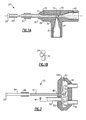
- valve 20 is shown in Figure 1A having a valve pin 22.
- Valve pin 22 has a head 24 that selectively seats in a valve seat 26 to control the flow of a fluid from an upstream location 35, to a port 36, through the valve seat 26, and to a downstream port 38 in a downstream connection 40.
- the valve pin 22 is coupled at 28 to a support shell 30.
- the support shell 30 is received within a bore 31, and coupled at 32 to the housing 34.
- the coupling at 28 and 32 may be performed by welding or other techniques known in the art.
- the support shell 30 is formed of a material having a different coefficient of thermal expansion than the valve pin 22. The difference in the coefficient of thermal expansion may be selected such that the coefficient of one of the materials will be at least twice the coefficient of the other. This will provide significant movement that can be achieved in a relatively short period of time to provide better control over the amount of a sample fluid, as an example.
- the support shell 30 and the housing 34 are formed of a stainless steel, and in particular stainless steel 304.
- the valve pin 22 may be formed of a tungsten. With such materials, the stainless steel will expand with a coefficient of thermal expansion that is three or four times the coefficient of the tungsten.
- support shell 30 is shown in Figure 1A as a cylindrical element surrounding a cylindrical valve pin, other embodiments of the support shell 30 which support the valve pin 22 for movement relative to the valve seat 26 can be utilized. As an example, spaced legs, or even a single support leg may support the valve pin 22 and cause movement of the valve pin 22 relative to the valve seat 26.
- the support shell 30 When exposed to heat, the support shell 30 will expand more than the valve pin 22. Since the two are connected together, this will cause the valve pin 22 to move to the left as shown in Figure 1A , and such that the head 24 moves from the position shown in Figure 1B at which it seals the connection, to the position shown at Figure 1A , wherein it allows fluid flow.
- a heater 42 may be provided to drive the expansion.
- the valve 20 may be responsive to environmental heat to provide this movement.
- the present invention is capable of providing very precise movement of the valve pin 22, such that extremely small amounts of fluid can be metered between port 36 to port 38.
- the valve 20 is particularly well suited for applications in which it is desirable to gather a small metered quantity of a gas.
- valve pin 22 is described as having the lower coefficient of thermal expansion relative to the support shell 30 or housing 34, the opposite could be utilized.
- heating is disclosed as actuating the valve 20
- cooling can be used to actuate the valve 20 in other embodiments.
- the valve 20 can be configured to passively open or close responsive to an increase or decrease temperature.
- FIG. 2 shows another embodiment of a valve 51 wherein a valve pin 43 is received within a support shell 44, and a heater coil 46 is provided.
- the valve pin 43 has a head 48 selectively received in an opening 54 in a diaphragm 50, where the diaphragm 50 at opening 54 serves as a valve seat for valve pin 43.
- Diaphragm 50 is secured within a housing 52.
- An inlet 56 extends into a chamber 57, and an outlet 58 extends outwardly of the chamber.
- a vacuum connection 62 is applied to an opposed side of the diaphragm.
- the materials and basic mounting of the support shell 44 and valve pin 43 may be as shown for the support shell 30 and valve pin 22 of the Figure 1A embodiment.
- the support shell 44 is supported within the housing 52.
- a weld joint 100 secures the diaphragm 50 within the housing 52.
- a frit 70 which may be formed of a powdered sintered metal, allows a controlled amount of leakage across its surface area in a pre-determined period of time.
- a very precise amount of gas may be sampled by simply actuating the valve 51 to pull the valve pin head 48 away from the opening 54, and while a vacuum is applied. This will sample a very precise amount of the fluid flowing between inlet 56 to outlet 58. The sample is drawn across the frit 70 and into connection 62.
- valve pins 22 and 43 may be held against the valve seat 26 and opening 54 in diaphragm 50 to provide a very tight fit, and a very secure seal to prevent leakage.
- the diaphragm 50 also allows the embodiment to be utilized in extremely cold environments. In such a cold environment, thermal expansion will operate to cause the sleeve and pin to be drawn toward the diaphragm to provide a very tight fit.
- the flexible diaphragm allows this movement, without damage to the overall valve. In prior art valves having moving valve parts, to provide a solid or high force holding the valve pin against the seat requires that same high force to be overcome.
- an embodiment of the valve 20 of Figure 1A was made to close off a fused silica capillary with an internal dimension of 100 micrometers (.0039 inches). With a two inch (50.8 mm) tungsten pin and 200 degree F (93.33 degrees C) rise in temperature, the gap between the valve pin 22 and the valve seat 26 is 0.0029 inches (73.66 mm). This gap is well suited for this 100 micrometers capillary application.
- the diameter of valve pin 22 and the wall thickness of the support shell 30 may be selected such that the valve seat 26 can be operated within the elastic limits of the material and hold helium leak rate of less than 10**-10 standard cubic centimeter per second (SCCS).
- SCCS standard cubic centimeter per second
- both the valve pin and the valve seat are polished after formation. However, it is preferred in this embodiment that only the valve pin is polished, with the valve seat left unpolished. Then, during initial run-in, the valve will form the actual contour of the valve seat such that a very tight and precise seat will be provided that will block almost all leakage.
- valves 20 and 51 of Figures 1A and 2 have no moving parts, making the valves 20 and 51 very reliable and simple to manufacture.
- Dead volume is very small, which is well suited for applications requiring low leak rate, low dead volume and reliable applications such as gas chromatography, flow switching devices, and vacuum systems. Of course, any other size and material may be used.
Landscapes
- Engineering & Computer Science (AREA)
- Chemical & Material Sciences (AREA)
- Combustion & Propulsion (AREA)
- General Engineering & Computer Science (AREA)
- Mechanical Engineering (AREA)
- Manufacturing & Machinery (AREA)
- Lift Valve (AREA)
- Temperature-Responsive Valves (AREA)
- Details Of Valves (AREA)
Abstract
Description
- This application relates to a valve that provides precise movement of a valve pin relative to a valve seat through the use of materials having distinct coefficients of thermal expansion.
- Valves are utilized in any number of applications to control the flow of fluids from one location to another. In a typical valve, a valve seat receives a valve pin, and when the valve pin is seated in the seat, fluid flow is blocked from an upstream location to a downstream location. The valve pin is moved relative to the valve seat to allow fluid flow.
- Typically, some actuator is provided to move the valve pin. The use of an actuator requires additional components, and is somewhat expensive. Moreover, the actuator may not provide precise movement, or adequate sealing.
- It has been proposed to utilize a material which expands or contracts with heating and cooling to form the valve pin. In such valves, the valve pin moves when heated to allow flow of fluid.
- A valve has a housing including a valve seat. A valve pin is supported by a support shell. The support shell and the valve pin have distinct coefficients of thermal expansion such that when exposed to a temperature change, the support shell moves differently than the valve pin. In this way, the valve pin can be caused to move toward and away from the valve seat to allow operation of the valve.
- These and other features of the present invention can be best understood from the following specification and drawings, the following of which is a brief description.
-
-
Figure 1A shows first embodiment. -
Figure 1B shows the first embodiment valve seated. -
Figure 2 shows a second embodiment. - A
valve 20 is shown inFigure 1A having avalve pin 22. Valvepin 22 has ahead 24 that selectively seats in avalve seat 26 to control the flow of a fluid from anupstream location 35, to aport 36, through thevalve seat 26, and to adownstream port 38 in adownstream connection 40. - The
valve pin 22 is coupled at 28 to asupport shell 30. Thesupport shell 30 is received within abore 31, and coupled at 32 to thehousing 34. The coupling at 28 and 32 may be performed by welding or other techniques known in the art. Thesupport shell 30 is formed of a material having a different coefficient of thermal expansion than thevalve pin 22. The difference in the coefficient of thermal expansion may be selected such that the coefficient of one of the materials will be at least twice the coefficient of the other. This will provide significant movement that can be achieved in a relatively short period of time to provide better control over the amount of a sample fluid, as an example. - In one embodiment, the
support shell 30 and thehousing 34 are formed of a stainless steel, and in particular stainless steel 304. In that same embodiment, thevalve pin 22 may be formed of a tungsten. With such materials, the stainless steel will expand with a coefficient of thermal expansion that is three or four times the coefficient of the tungsten. - While the
support shell 30 is shown inFigure 1A as a cylindrical element surrounding a cylindrical valve pin, other embodiments of thesupport shell 30 which support thevalve pin 22 for movement relative to thevalve seat 26 can be utilized. As an example, spaced legs, or even a single support leg may support thevalve pin 22 and cause movement of thevalve pin 22 relative to thevalve seat 26. - When exposed to heat, the
support shell 30 will expand more than thevalve pin 22. Since the two are connected together, this will cause thevalve pin 22 to move to the left as shown inFigure 1A , and such that thehead 24 moves from the position shown inFigure 1B at which it seals the connection, to the position shown atFigure 1A , wherein it allows fluid flow. Aheater 42 may be provided to drive the expansion. Alternatively, thevalve 20 may be responsive to environmental heat to provide this movement. - The present invention is capable of providing very precise movement of the
valve pin 22, such that extremely small amounts of fluid can be metered betweenport 36 toport 38. Thevalve 20 is particularly well suited for applications in which it is desirable to gather a small metered quantity of a gas. - While the
valve pin 22 is described as having the lower coefficient of thermal expansion relative to thesupport shell 30 orhousing 34, the opposite could be utilized. In addition, while heating is disclosed as actuating thevalve 20, in fact cooling can be used to actuate thevalve 20 in other embodiments. For example, depending upon the materials selected for thevalve pin 22 and thesupport shell 30, thevalve 20 can be configured to passively open or close responsive to an increase or decrease temperature. -
Figure 2 shows another embodiment of avalve 51 wherein avalve pin 43 is received within asupport shell 44, and aheater coil 46 is provided. Thevalve pin 43 has ahead 48 selectively received in anopening 54 in adiaphragm 50, where thediaphragm 50 at opening 54 serves as a valve seat forvalve pin 43.Diaphragm 50 is secured within ahousing 52. Aninlet 56 extends into achamber 57, and anoutlet 58 extends outwardly of the chamber. Avacuum connection 62 is applied to an opposed side of the diaphragm. - In the embodiment shown in
Figure 2 , the materials and basic mounting of thesupport shell 44 andvalve pin 43 may be as shown for thesupport shell 30 andvalve pin 22 of theFigure 1A embodiment. As shown inFigure 2 , thesupport shell 44 is supported within thehousing 52. Aweld joint 100 secures thediaphragm 50 within thehousing 52. - A frit 70, which may be formed of a powdered sintered metal, allows a controlled amount of leakage across its surface area in a pre-determined period of time. In this embodiment, a very precise amount of gas may be sampled by simply actuating the
valve 51 to pull thevalve pin head 48 away from theopening 54, and while a vacuum is applied. This will sample a very precise amount of the fluid flowing betweeninlet 56 tooutlet 58. The sample is drawn across the frit 70 and intoconnection 62. - In the embodiments as depicted in
Figures 1A and 2 , thevalve pins valve seat 26 and opening 54 indiaphragm 50 to provide a very tight fit, and a very secure seal to prevent leakage. Thediaphragm 50 also allows the embodiment to be utilized in extremely cold environments. In such a cold environment, thermal expansion will operate to cause the sleeve and pin to be drawn toward the diaphragm to provide a very tight fit. The flexible diaphragm allows this movement, without damage to the overall valve. In prior art valves having moving valve parts, to provide a solid or high force holding the valve pin against the seat requires that same high force to be overcome. However, since the expansion of the materials in the disclosed embodiments is what causes the movement here, that concern does not apply as much as in the prior art. Also, very precise movement of a valve element relative to its housing is provided by the disclosed embodiments, and precise metering can be achieved. - In one application, an embodiment of the
valve 20 ofFigure 1A was made to close off a fused silica capillary with an internal dimension of 100 micrometers (.0039 inches). With a two inch (50.8 mm) tungsten pin and 200 degree F (93.33 degrees C) rise in temperature, the gap between thevalve pin 22 and thevalve seat 26 is 0.0029 inches (73.66 mm). This gap is well suited for this 100 micrometers capillary application. The diameter ofvalve pin 22 and the wall thickness of thesupport shell 30 may be selected such that thevalve seat 26 can be operated within the elastic limits of the material and hold helium leak rate of less than 10**-10 standard cubic centimeter per second (SCCS). A worker of ordinary skill in the art, armed with the coefficients of expansion, and the particular sizes of the components, would be able to calculate the relative movement of thevalve pin 22, and thesupport shell 30 to achieve this tight control. - In many valve applications, both the valve pin and the valve seat are polished after formation. However, it is preferred in this embodiment that only the valve pin is polished, with the valve seat left unpolished. Then, during initial run-in, the valve will form the actual contour of the valve seat such that a very tight and precise seat will be provided that will block almost all leakage.
- The
valves Figures 1A and 2 have no moving parts, making thevalves - Although embodiments of this invention have been disclosed, a worker of ordinary skill in this art would recognize that certain modifications would come within the scope of this invention. For that reason, the following claims should be studied to determine the true scope and content of this invention.
Claims (13)
- A valve comprising:a housing including a valve seat;a valve pin, said valve pin being supported by a support shell; andsaid support shell and said valve pin having different coefficients of thermal expansion such that when exposed to a temperature change, movement of said support shell and said valve pin are different, and said valve pin can be caused to move toward and away from said valve seat to allow operation of said valve.
- The valve as set forth in claim 1, wherein said valve pin has a lower coefficient of thermal expansion than said support shell.
- The valve as set forth in claim 1 or 2, wherein the coefficient of thermal expansion of one of said support shell and said valve pin is at least twice as high as the coefficient of thermal expansion of the other.
- The valve as set forth in claim 1, 2 or 3, wherein an end of said valve pin and an end of said support shell remote from said seat, are secured together such that the said movement of said support shell causes said valve pin to move relative to said valve seat.
- The valve as set forth in claim 1, 2, 3 or 4, wherein a heater is provided to cause said movement of said valve pin relative to said valve seat.
- The valve as set forth in claim 5, wherein said heater heats said support shell to cause said shell to expand, and cause movement of said valve pin.
- The valve as set forth in any preceding claim, wherein said support shell is secured in said valve seat housing, and such that expansion of said support shell at a greater rate than expansion of said valve pin causes movement of said valve pin.
- The valve as set forth in any preceding claim, wherein said valve seat is formed in a diaphragm member.
- The valve as set forth in claim 8, wherein said valve seat is formed as an opening in said diaphragm, and a material allows leakage of a very precise amount of fluid across the material and to said opening, and said valve pin being pulled away from said valve seat, such that a very precise amount of fluid can leak across the material, and to a sampling outlet.
- The valve as set forth in any preceding claim, wherein said valve pin is formed of tungsten, and said support shell is formed of a stainless steel.
- The valve as set forth in any preceding claim, wherein said support shell is a cylindrical element surrounding said valve pin.
- A method of operating a valve including the steps of:(a) providing a housing including a valve seat;(b) connecting a valve pin to a support shell, said support shell and said valve pin having distinct coefficients of thermal expansion; and(c) said valve pin and said support shell moving in response to a temperature change with movement of said support shell and said valve pin being different, and said valve pin moving toward or away from said valve seat to allow operation of said valve.
- The method as set forth in claim 12, wherein heat is applied to said support shell and to said valve pin to cause said movement of said valve pin.
Applications Claiming Priority (1)
| Application Number | Priority Date | Filing Date | Title |
|---|---|---|---|
| US12/714,662 US20110209769A1 (en) | 2010-03-01 | 2010-03-01 | Thermally operated valve |
Publications (2)
| Publication Number | Publication Date |
|---|---|
| EP2366925A1 true EP2366925A1 (en) | 2011-09-21 |
| EP2366925B1 EP2366925B1 (en) | 2012-12-19 |
Family
ID=43977928
Family Applications (1)
| Application Number | Title | Priority Date | Filing Date |
|---|---|---|---|
| EP20110250236 Not-in-force EP2366925B1 (en) | 2010-03-01 | 2011-03-01 | Thermally operated valve |
Country Status (5)
| Country | Link |
|---|---|
| US (1) | US20110209769A1 (en) |
| EP (1) | EP2366925B1 (en) |
| JP (1) | JP2011179685A (en) |
| CN (1) | CN102192365A (en) |
| IL (1) | IL211488A0 (en) |
Families Citing this family (4)
| Publication number | Priority date | Publication date | Assignee | Title |
|---|---|---|---|---|
| DE202013002281U1 (en) * | 2013-03-11 | 2014-06-12 | Neoperl Gmbh | Sanitary installation part and shower arrangement |
| US20160298783A1 (en) | 2015-04-09 | 2016-10-13 | Hamilton Sundstrand Corporation | Thermally actuated flow control valve |
| US10877498B2 (en) | 2017-10-27 | 2020-12-29 | Brasscraft Manufacturing Company | Excess flow and thermal valve |
| US11946460B1 (en) * | 2022-12-23 | 2024-04-02 | Raytheon Company | Thermal-mechanical linear actuator |
Citations (7)
| Publication number | Priority date | Publication date | Assignee | Title |
|---|---|---|---|---|
| US3340893A (en) * | 1964-11-20 | 1967-09-12 | Heald Machine Co | Throttle |
| US3696997A (en) * | 1971-04-09 | 1972-10-10 | Vernay Laboratories | Valve repsonsive to temperature changes over a limited range |
| FR2136023A5 (en) * | 1971-04-08 | 1972-12-22 | Vernay Laboratories | |
| US3833171A (en) * | 1973-07-18 | 1974-09-03 | Vernay Laboratories | Temperature responsive valve assembly |
| DE3733740A1 (en) * | 1987-10-06 | 1989-04-20 | Danfoss As | DAMPING ARRANGEMENT FOR THE VIBRATION DAMPING OF VALVES CONTROLLED BY PRESSURE FLUID |
| US5879594A (en) * | 1997-07-10 | 1999-03-09 | Holtzman; Barry L. | Temperature responsive pressure splitter |
| GB2390663A (en) * | 2002-07-12 | 2004-01-14 | Rolls Royce Plc | Temperature responsive valve |
Family Cites Families (20)
| Publication number | Priority date | Publication date | Assignee | Title |
|---|---|---|---|---|
| US2830621A (en) * | 1955-06-10 | 1958-04-15 | Cleveland Pneumatic Tool Co | Thermal compensating needle valve |
| US3322345A (en) * | 1965-02-15 | 1967-05-30 | Sparton Corp | Temperature regulated flow control valve |
| US3836074A (en) * | 1972-08-30 | 1974-09-17 | Pneumo Dynamics Corp | Bi-thermal bleed valve |
| JPS5197689U (en) * | 1975-02-05 | 1976-08-05 | ||
| US3967781A (en) * | 1975-02-12 | 1976-07-06 | Emerson Electric Co. | Electrically operated expansion valve for refrigeration control |
| US3977600A (en) * | 1975-11-06 | 1976-08-31 | J. I. Case Company | Temperature responsive fluid flow regulator |
| US4402337A (en) * | 1980-10-10 | 1983-09-06 | Shell Oil Company | Valve provided with a thermally-actuated mechanism for pressing valve seats against a valve gate body |
| US5058856A (en) * | 1991-05-08 | 1991-10-22 | Hewlett-Packard Company | Thermally-actuated microminiature valve |
| US5316437A (en) * | 1993-02-19 | 1994-05-31 | General Electric Company | Gas turbine engine structural frame assembly having a thermally actuated valve for modulating a flow of hot gases through the frame hub |
| US5899218A (en) * | 1995-06-28 | 1999-05-04 | Basf Corporation | Plate-type valve and method of use |
| US5655892A (en) * | 1996-08-21 | 1997-08-12 | Walbro Corporation | Thermally actuated fuel pump vapor vent valve |
| JP4059973B2 (en) * | 1998-03-30 | 2008-03-12 | パロマ工業株式会社 | Gas water tap |
| JP4596640B2 (en) * | 2000-10-05 | 2010-12-08 | 株式会社不二工機 | Variable orifice device |
| US6886665B2 (en) * | 2002-12-06 | 2005-05-03 | Hamilton Sundstrand | Lubrication system valve |
| US7159614B2 (en) * | 2002-12-31 | 2007-01-09 | Hamilton Sundstrand | Assembly for in-line valve actuation and indication |
| JP4482654B2 (en) * | 2004-08-06 | 2010-06-16 | 株式会社アライドマテリアル | Heat resistant material for high energy density equipment |
| US7080591B2 (en) * | 2004-09-14 | 2006-07-25 | Hamilton Sundstrand | Non-symmetrical seal plate and valve housing |
| EP1951430A2 (en) * | 2005-09-20 | 2008-08-06 | Koninklijke Philips Electronics N.V. | A microfluidic regulating device |
| US7314198B2 (en) * | 2006-02-10 | 2008-01-01 | Goodrich Corporation | Aircraft evacuation slide with thermally actuated gas relief valve |
| US7584782B1 (en) * | 2006-08-28 | 2009-09-08 | Hamilton Sundstrand Corporation | Valve defining modulated and unmodulated flow paths |
-
2010
- 2010-03-01 US US12/714,662 patent/US20110209769A1/en not_active Abandoned
-
2011
- 2011-02-10 JP JP2011026772A patent/JP2011179685A/en not_active Ceased
- 2011-02-28 IL IL211488A patent/IL211488A0/en unknown
- 2011-03-01 EP EP20110250236 patent/EP2366925B1/en not_active Not-in-force
- 2011-03-01 CN CN2011100485719A patent/CN102192365A/en active Pending
Patent Citations (7)
| Publication number | Priority date | Publication date | Assignee | Title |
|---|---|---|---|---|
| US3340893A (en) * | 1964-11-20 | 1967-09-12 | Heald Machine Co | Throttle |
| FR2136023A5 (en) * | 1971-04-08 | 1972-12-22 | Vernay Laboratories | |
| US3696997A (en) * | 1971-04-09 | 1972-10-10 | Vernay Laboratories | Valve repsonsive to temperature changes over a limited range |
| US3833171A (en) * | 1973-07-18 | 1974-09-03 | Vernay Laboratories | Temperature responsive valve assembly |
| DE3733740A1 (en) * | 1987-10-06 | 1989-04-20 | Danfoss As | DAMPING ARRANGEMENT FOR THE VIBRATION DAMPING OF VALVES CONTROLLED BY PRESSURE FLUID |
| US5879594A (en) * | 1997-07-10 | 1999-03-09 | Holtzman; Barry L. | Temperature responsive pressure splitter |
| GB2390663A (en) * | 2002-07-12 | 2004-01-14 | Rolls Royce Plc | Temperature responsive valve |
Also Published As
| Publication number | Publication date |
|---|---|
| US20110209769A1 (en) | 2011-09-01 |
| JP2011179685A (en) | 2011-09-15 |
| EP2366925B1 (en) | 2012-12-19 |
| IL211488A0 (en) | 2011-06-30 |
| CN102192365A (en) | 2011-09-21 |
Similar Documents
| Publication | Publication Date | Title |
|---|---|---|
| US8443830B2 (en) | Heater built-in valve | |
| CN100334515C (en) | Flow controller | |
| EP2366925B1 (en) | Thermally operated valve | |
| KR102456760B1 (en) | Piezo actuator type valve | |
| Henning et al. | A thermopneumatically actuated microvalve for liquid expansion and proportional control | |
| EP2359037B1 (en) | Valve | |
| US10125988B2 (en) | Two-stage fluid control valve having a first stage mechanical valve and a second stage microvalve | |
| JP2018096473A (en) | Control valve | |
| CN103314242B (en) | For the device of the flow velocity of controlled cooling model agent | |
| US11168805B2 (en) | Thermally actuated flow control valve | |
| US3669408A (en) | Metal to metal sea for extreme temperature applications | |
| US20160097463A1 (en) | Valve | |
| RU2562713C2 (en) | Control valve for fluid system and pressure control valve | |
| CN102619998A (en) | Thermal expansion valve | |
| CN114198534B (en) | Mixing unit and mixing tap comprising such a mixing unit | |
| Dighe et al. | Single-use MEMS sealing valve with integrated actuation for ultra low-leak vacuum applications | |
| JP4596830B2 (en) | Four-way valve | |
| US20250283536A1 (en) | Valve For A Cooling System | |
| CN108431473B (en) | Pipe distribution system and functional unit for a pipe distribution system | |
| RU134273U1 (en) | THERMOSTATIC VALVE | |
| JP2006349142A (en) | Low leakage poppet solenoid valve | |
| JP2008089087A (en) | Flow adjustment valve | |
| WO2015002855A1 (en) | Heated fluid delivery with thermal management | |
| JPH0674362A (en) | Utilizing valve shape memory alloy | |
| DYSART et al. | 7.8 Regulators—Temperature |
Legal Events
| Date | Code | Title | Description |
|---|---|---|---|
| PUAI | Public reference made under article 153(3) epc to a published international application that has entered the european phase |
Free format text: ORIGINAL CODE: 0009012 |
|
| AK | Designated contracting states |
Kind code of ref document: A1 Designated state(s): AL AT BE BG CH CY CZ DE DK EE ES FI FR GB GR HR HU IE IS IT LI LT LU LV MC MK MT NL NO PL PT RO RS SE SI SK SM TR |
|
| AX | Request for extension of the european patent |
Extension state: BA ME |
|
| 17P | Request for examination filed |
Effective date: 20120320 |
|
| RIC1 | Information provided on ipc code assigned before grant |
Ipc: G05D 23/02 20060101ALI20120516BHEP Ipc: F16K 31/00 20060101AFI20120516BHEP |
|
| GRAP | Despatch of communication of intention to grant a patent |
Free format text: ORIGINAL CODE: EPIDOSNIGR1 |
|
| GRAS | Grant fee paid |
Free format text: ORIGINAL CODE: EPIDOSNIGR3 |
|
| GRAA | (expected) grant |
Free format text: ORIGINAL CODE: 0009210 |
|
| AK | Designated contracting states |
Kind code of ref document: B1 Designated state(s): AL AT BE BG CH CY CZ DE DK EE ES FI FR GB GR HR HU IE IS IT LI LT LU LV MC MK MT NL NO PL PT RO RS SE SI SK SM TR |
|
| REG | Reference to a national code |
Ref country code: GB Ref legal event code: FG4D |
|
| REG | Reference to a national code |
Ref country code: CH Ref legal event code: EP |
|
| RAP2 | Party data changed (patent owner data changed or rights of a patent transferred) |
Owner name: HAMILTON SUNDSTRAND SPACE SYSTEMS INTERNATIONAL, I |
|
| REG | Reference to a national code |
Ref country code: AT Ref legal event code: REF Ref document number: 589598 Country of ref document: AT Kind code of ref document: T Effective date: 20130115 |
|
| REG | Reference to a national code |
Ref country code: DE Ref legal event code: R096 Ref document number: 602011000627 Country of ref document: DE Effective date: 20130214 |
|
| PG25 | Lapsed in a contracting state [announced via postgrant information from national office to epo] |
Ref country code: HR Free format text: LAPSE BECAUSE OF FAILURE TO SUBMIT A TRANSLATION OF THE DESCRIPTION OR TO PAY THE FEE WITHIN THE PRESCRIBED TIME-LIMIT Effective date: 20121219 Ref country code: LT Free format text: LAPSE BECAUSE OF FAILURE TO SUBMIT A TRANSLATION OF THE DESCRIPTION OR TO PAY THE FEE WITHIN THE PRESCRIBED TIME-LIMIT Effective date: 20121219 Ref country code: SE Free format text: LAPSE BECAUSE OF FAILURE TO SUBMIT A TRANSLATION OF THE DESCRIPTION OR TO PAY THE FEE WITHIN THE PRESCRIBED TIME-LIMIT Effective date: 20121219 Ref country code: FI Free format text: LAPSE BECAUSE OF FAILURE TO SUBMIT A TRANSLATION OF THE DESCRIPTION OR TO PAY THE FEE WITHIN THE PRESCRIBED TIME-LIMIT Effective date: 20121219 Ref country code: ES Free format text: LAPSE BECAUSE OF FAILURE TO SUBMIT A TRANSLATION OF THE DESCRIPTION OR TO PAY THE FEE WITHIN THE PRESCRIBED TIME-LIMIT Effective date: 20130330 Ref country code: NO Free format text: LAPSE BECAUSE OF FAILURE TO SUBMIT A TRANSLATION OF THE DESCRIPTION OR TO PAY THE FEE WITHIN THE PRESCRIBED TIME-LIMIT Effective date: 20130319 |
|
| PGFP | Annual fee paid to national office [announced via postgrant information from national office to epo] |
Ref country code: FR Payment date: 20130325 Year of fee payment: 3 |
|
| REG | Reference to a national code |
Ref country code: NL Ref legal event code: VDEP Effective date: 20121219 Ref country code: AT Ref legal event code: MK05 Ref document number: 589598 Country of ref document: AT Kind code of ref document: T Effective date: 20121219 |
|
| REG | Reference to a national code |
Ref country code: LT Ref legal event code: MG4D |
|
| PG25 | Lapsed in a contracting state [announced via postgrant information from national office to epo] |
Ref country code: GR Free format text: LAPSE BECAUSE OF FAILURE TO SUBMIT A TRANSLATION OF THE DESCRIPTION OR TO PAY THE FEE WITHIN THE PRESCRIBED TIME-LIMIT Effective date: 20130320 Ref country code: LV Free format text: LAPSE BECAUSE OF FAILURE TO SUBMIT A TRANSLATION OF THE DESCRIPTION OR TO PAY THE FEE WITHIN THE PRESCRIBED TIME-LIMIT Effective date: 20121219 Ref country code: SI Free format text: LAPSE BECAUSE OF FAILURE TO SUBMIT A TRANSLATION OF THE DESCRIPTION OR TO PAY THE FEE WITHIN THE PRESCRIBED TIME-LIMIT Effective date: 20121219 |
|
| PG25 | Lapsed in a contracting state [announced via postgrant information from national office to epo] |
Ref country code: BG Free format text: LAPSE BECAUSE OF FAILURE TO SUBMIT A TRANSLATION OF THE DESCRIPTION OR TO PAY THE FEE WITHIN THE PRESCRIBED TIME-LIMIT Effective date: 20130319 Ref country code: EE Free format text: LAPSE BECAUSE OF FAILURE TO SUBMIT A TRANSLATION OF THE DESCRIPTION OR TO PAY THE FEE WITHIN THE PRESCRIBED TIME-LIMIT Effective date: 20121219 Ref country code: IS Free format text: LAPSE BECAUSE OF FAILURE TO SUBMIT A TRANSLATION OF THE DESCRIPTION OR TO PAY THE FEE WITHIN THE PRESCRIBED TIME-LIMIT Effective date: 20130419 Ref country code: BE Free format text: LAPSE BECAUSE OF FAILURE TO SUBMIT A TRANSLATION OF THE DESCRIPTION OR TO PAY THE FEE WITHIN THE PRESCRIBED TIME-LIMIT Effective date: 20121219 Ref country code: CZ Free format text: LAPSE BECAUSE OF FAILURE TO SUBMIT A TRANSLATION OF THE DESCRIPTION OR TO PAY THE FEE WITHIN THE PRESCRIBED TIME-LIMIT Effective date: 20121219 Ref country code: AT Free format text: LAPSE BECAUSE OF FAILURE TO SUBMIT A TRANSLATION OF THE DESCRIPTION OR TO PAY THE FEE WITHIN THE PRESCRIBED TIME-LIMIT Effective date: 20121219 Ref country code: SK Free format text: LAPSE BECAUSE OF FAILURE TO SUBMIT A TRANSLATION OF THE DESCRIPTION OR TO PAY THE FEE WITHIN THE PRESCRIBED TIME-LIMIT Effective date: 20121219 Ref country code: RS Free format text: LAPSE BECAUSE OF FAILURE TO SUBMIT A TRANSLATION OF THE DESCRIPTION OR TO PAY THE FEE WITHIN THE PRESCRIBED TIME-LIMIT Effective date: 20121219 |
|
| PG25 | Lapsed in a contracting state [announced via postgrant information from national office to epo] |
Ref country code: RO Free format text: LAPSE BECAUSE OF FAILURE TO SUBMIT A TRANSLATION OF THE DESCRIPTION OR TO PAY THE FEE WITHIN THE PRESCRIBED TIME-LIMIT Effective date: 20121219 Ref country code: PT Free format text: LAPSE BECAUSE OF FAILURE TO SUBMIT A TRANSLATION OF THE DESCRIPTION OR TO PAY THE FEE WITHIN THE PRESCRIBED TIME-LIMIT Effective date: 20130419 Ref country code: PL Free format text: LAPSE BECAUSE OF FAILURE TO SUBMIT A TRANSLATION OF THE DESCRIPTION OR TO PAY THE FEE WITHIN THE PRESCRIBED TIME-LIMIT Effective date: 20121219 Ref country code: NL Free format text: LAPSE BECAUSE OF FAILURE TO SUBMIT A TRANSLATION OF THE DESCRIPTION OR TO PAY THE FEE WITHIN THE PRESCRIBED TIME-LIMIT Effective date: 20121219 |
|
| PLBE | No opposition filed within time limit |
Free format text: ORIGINAL CODE: 0009261 |
|
| STAA | Information on the status of an ep patent application or granted ep patent |
Free format text: STATUS: NO OPPOSITION FILED WITHIN TIME LIMIT |
|
| PG25 | Lapsed in a contracting state [announced via postgrant information from national office to epo] |
Ref country code: MC Free format text: LAPSE BECAUSE OF NON-PAYMENT OF DUE FEES Effective date: 20130331 Ref country code: DK Free format text: LAPSE BECAUSE OF FAILURE TO SUBMIT A TRANSLATION OF THE DESCRIPTION OR TO PAY THE FEE WITHIN THE PRESCRIBED TIME-LIMIT Effective date: 20121219 |
|
| 26N | No opposition filed |
Effective date: 20130920 |
|
| PG25 | Lapsed in a contracting state [announced via postgrant information from national office to epo] |
Ref country code: CY Free format text: LAPSE BECAUSE OF FAILURE TO SUBMIT A TRANSLATION OF THE DESCRIPTION OR TO PAY THE FEE WITHIN THE PRESCRIBED TIME-LIMIT Effective date: 20121219 |
|
| PG25 | Lapsed in a contracting state [announced via postgrant information from national office to epo] |
Ref country code: IT Free format text: LAPSE BECAUSE OF FAILURE TO SUBMIT A TRANSLATION OF THE DESCRIPTION OR TO PAY THE FEE WITHIN THE PRESCRIBED TIME-LIMIT Effective date: 20121219 |
|
| REG | Reference to a national code |
Ref country code: IE Ref legal event code: MM4A |
|
| REG | Reference to a national code |
Ref country code: DE Ref legal event code: R097 Ref document number: 602011000627 Country of ref document: DE Effective date: 20130920 |
|
| PG25 | Lapsed in a contracting state [announced via postgrant information from national office to epo] |
Ref country code: AL Free format text: LAPSE BECAUSE OF FAILURE TO SUBMIT A TRANSLATION OF THE DESCRIPTION OR TO PAY THE FEE WITHIN THE PRESCRIBED TIME-LIMIT Effective date: 20121219 Ref country code: IE Free format text: LAPSE BECAUSE OF NON-PAYMENT OF DUE FEES Effective date: 20130301 |
|
| PG25 | Lapsed in a contracting state [announced via postgrant information from national office to epo] |
Ref country code: MT Free format text: LAPSE BECAUSE OF FAILURE TO SUBMIT A TRANSLATION OF THE DESCRIPTION OR TO PAY THE FEE WITHIN THE PRESCRIBED TIME-LIMIT Effective date: 20121219 |
|
| PGFP | Annual fee paid to national office [announced via postgrant information from national office to epo] |
Ref country code: DE Payment date: 20130227 Year of fee payment: 3 |
|
| REG | Reference to a national code |
Ref country code: DE Ref legal event code: R119 Ref document number: 602011000627 Country of ref document: DE |
|
| REG | Reference to a national code |
Ref country code: CH Ref legal event code: PL |
|
| REG | Reference to a national code |
Ref country code: FR Ref legal event code: ST Effective date: 20141128 |
|
| REG | Reference to a national code |
Ref country code: DE Ref legal event code: R119 Ref document number: 602011000627 Country of ref document: DE Effective date: 20141001 |
|
| PG25 | Lapsed in a contracting state [announced via postgrant information from national office to epo] |
Ref country code: DE Free format text: LAPSE BECAUSE OF NON-PAYMENT OF DUE FEES Effective date: 20141001 Ref country code: LI Free format text: LAPSE BECAUSE OF NON-PAYMENT OF DUE FEES Effective date: 20140331 Ref country code: CH Free format text: LAPSE BECAUSE OF NON-PAYMENT OF DUE FEES Effective date: 20140331 Ref country code: FR Free format text: LAPSE BECAUSE OF NON-PAYMENT OF DUE FEES Effective date: 20140331 |
|
| PG25 | Lapsed in a contracting state [announced via postgrant information from national office to epo] |
Ref country code: SM Free format text: LAPSE BECAUSE OF FAILURE TO SUBMIT A TRANSLATION OF THE DESCRIPTION OR TO PAY THE FEE WITHIN THE PRESCRIBED TIME-LIMIT Effective date: 20121219 |
|
| PG25 | Lapsed in a contracting state [announced via postgrant information from national office to epo] |
Ref country code: TR Free format text: LAPSE BECAUSE OF FAILURE TO SUBMIT A TRANSLATION OF THE DESCRIPTION OR TO PAY THE FEE WITHIN THE PRESCRIBED TIME-LIMIT Effective date: 20121219 |
|
| PG25 | Lapsed in a contracting state [announced via postgrant information from national office to epo] |
Ref country code: MK Free format text: LAPSE BECAUSE OF FAILURE TO SUBMIT A TRANSLATION OF THE DESCRIPTION OR TO PAY THE FEE WITHIN THE PRESCRIBED TIME-LIMIT Effective date: 20121219 Ref country code: HU Free format text: LAPSE BECAUSE OF FAILURE TO SUBMIT A TRANSLATION OF THE DESCRIPTION OR TO PAY THE FEE WITHIN THE PRESCRIBED TIME-LIMIT; INVALID AB INITIO Effective date: 20110301 Ref country code: LU Free format text: LAPSE BECAUSE OF NON-PAYMENT OF DUE FEES Effective date: 20130301 |
|
| PGFP | Annual fee paid to national office [announced via postgrant information from national office to epo] |
Ref country code: GB Payment date: 20230222 Year of fee payment: 13 |
|
| GBPC | Gb: european patent ceased through non-payment of renewal fee |
Effective date: 20240301 |
|
| PG25 | Lapsed in a contracting state [announced via postgrant information from national office to epo] |
Ref country code: GB Free format text: LAPSE BECAUSE OF NON-PAYMENT OF DUE FEES Effective date: 20240301 |
|
| PG25 | Lapsed in a contracting state [announced via postgrant information from national office to epo] |
Ref country code: GB Free format text: LAPSE BECAUSE OF NON-PAYMENT OF DUE FEES Effective date: 20240301 |