EP2365893B1 - Method for determining the position of a tool - Google Patents
Method for determining the position of a tool Download PDFInfo
- Publication number
- EP2365893B1 EP2365893B1 EP11701387.0A EP11701387A EP2365893B1 EP 2365893 B1 EP2365893 B1 EP 2365893B1 EP 11701387 A EP11701387 A EP 11701387A EP 2365893 B1 EP2365893 B1 EP 2365893B1
- Authority
- EP
- European Patent Office
- Prior art keywords
- tool
- measuring point
- machine
- workpiece
- carrier
- Prior art date
- Legal status (The legal status is an assumption and is not a legal conclusion. Google has not performed a legal analysis and makes no representation as to the accuracy of the status listed.)
- Active
Links
- 238000000034 method Methods 0.000 title claims description 40
- 238000005259 measurement Methods 0.000 claims abstract description 31
- 238000003754 machining Methods 0.000 claims abstract description 20
- 238000006073 displacement reaction Methods 0.000 claims description 15
- 230000008859 change Effects 0.000 claims description 8
- 238000012545 processing Methods 0.000 claims description 7
- 238000010276 construction Methods 0.000 description 9
- 238000013461 design Methods 0.000 description 5
- 238000004519 manufacturing process Methods 0.000 description 4
- 230000008569 process Effects 0.000 description 4
- 230000004888 barrier function Effects 0.000 description 3
- 230000008901 benefit Effects 0.000 description 3
- 238000012937 correction Methods 0.000 description 3
- 238000013178 mathematical model Methods 0.000 description 3
- 229910001374 Invar Inorganic materials 0.000 description 2
- 229920000271 Kevlar® Polymers 0.000 description 2
- 238000004364 calculation method Methods 0.000 description 2
- 239000005068 cooling lubricant Substances 0.000 description 2
- 230000008878 coupling Effects 0.000 description 2
- 238000010168 coupling process Methods 0.000 description 2
- 238000005859 coupling reaction Methods 0.000 description 2
- 239000011521 glass Substances 0.000 description 2
- 238000010438 heat treatment Methods 0.000 description 2
- 239000004761 kevlar Substances 0.000 description 2
- 230000003287 optical effect Effects 0.000 description 2
- 238000002849 thermal shift Methods 0.000 description 2
- 229910000831 Steel Inorganic materials 0.000 description 1
- 230000005540 biological transmission Effects 0.000 description 1
- 238000011109 contamination Methods 0.000 description 1
- 238000005520 cutting process Methods 0.000 description 1
- 238000001514 detection method Methods 0.000 description 1
- 238000005553 drilling Methods 0.000 description 1
- 230000000694 effects Effects 0.000 description 1
- 238000005516 engineering process Methods 0.000 description 1
- 230000001939 inductive effect Effects 0.000 description 1
- 238000002955 isolation Methods 0.000 description 1
- 239000000463 material Substances 0.000 description 1
- 230000007246 mechanism Effects 0.000 description 1
- 239000002184 metal Substances 0.000 description 1
- 239000002986 polymer concrete Substances 0.000 description 1
- 230000009467 reduction Effects 0.000 description 1
- 239000010959 steel Substances 0.000 description 1
- 239000013589 supplement Substances 0.000 description 1
- 238000012546 transfer Methods 0.000 description 1
Images


Classifications
-
- B—PERFORMING OPERATIONS; TRANSPORTING
- B23—MACHINE TOOLS; METAL-WORKING NOT OTHERWISE PROVIDED FOR
- B23Q—DETAILS, COMPONENTS, OR ACCESSORIES FOR MACHINE TOOLS, e.g. ARRANGEMENTS FOR COPYING OR CONTROLLING; MACHINE TOOLS IN GENERAL CHARACTERISED BY THE CONSTRUCTION OF PARTICULAR DETAILS OR COMPONENTS; COMBINATIONS OR ASSOCIATIONS OF METAL-WORKING MACHINES, NOT DIRECTED TO A PARTICULAR RESULT
- B23Q17/00—Arrangements for observing, indicating or measuring on machine tools
- B23Q17/22—Arrangements for observing, indicating or measuring on machine tools for indicating or measuring existing or desired position of tool or work
-
- B—PERFORMING OPERATIONS; TRANSPORTING
- B23—MACHINE TOOLS; METAL-WORKING NOT OTHERWISE PROVIDED FOR
- B23Q—DETAILS, COMPONENTS, OR ACCESSORIES FOR MACHINE TOOLS, e.g. ARRANGEMENTS FOR COPYING OR CONTROLLING; MACHINE TOOLS IN GENERAL CHARACTERISED BY THE CONSTRUCTION OF PARTICULAR DETAILS OR COMPONENTS; COMBINATIONS OR ASSOCIATIONS OF METAL-WORKING MACHINES, NOT DIRECTED TO A PARTICULAR RESULT
- B23Q11/00—Accessories fitted to machine tools for keeping tools or parts of the machine in good working condition or for cooling work; Safety devices specially combined with or arranged in, or specially adapted for use in connection with, machine tools
- B23Q11/0003—Arrangements for preventing undesired thermal effects on tools or parts of the machine
- B23Q11/0007—Arrangements for preventing undesired thermal effects on tools or parts of the machine by compensating occurring thermal dilations
Definitions
- the present invention relates to a method for determining the position of a tool in a machine tool, which has a workpiece carrier as well as a construction element movable relative to the workpiece carrier and a machine part tool carrier, in which the tool for machining a workpiece carried by the workpiece carrier workpiece is clamped, wherein a tool-near measuring point and on the machine part at least two further measuring points are provided on the tool carrier, the relative position of the other measuring points to a coordinate origin point is known, and the position of the tool-near measuring point is determined to the coordinate origin.
- the present invention further relates to a machine tool, which has a workpiece carrier as well as a tool carrier which can be moved relative to the workpiece carrier and a machine part via construction elements, into which a tool for processing a workpiece carried by the workpiece carrier is clamped.
- Such methods and machine tools are for example from the DE 198 53 757 C2 as well as the DE 197 43 149 A1 known.
- the respective measuring system is arranged in both known machine tools directly in the working space of the machine tool and exposed to the prevailing soiling there.
- a robot system is known in which length measuring systems are integrated into the telescopic arms that move the arms of the robot.
- a positioning method is known in which the position of a positionable in space part is determined by optical methods.
- the WO 97/46925 A1 describes the closest prior art according to the preamble of claims 1 and 8 with a system in which two laser interferometers are used to determine the position of a machining head in space.
- the WO 2005/019769 A1 describes a method for the determination of geometric deviations of technical multi-body systems, in which successively measuring points are approached, which may not all lie in one plane.
- A1 known method is provided in the working space of a machine tool, a separate measuring system in the form of a laser light barrier, which is arranged obliquely to the linear axes of the spindle head. At certain times a measuring tool is clamped in the spindle head, with which the photocell is then approached parallel to the axes of travel and the position of the spindle head is determined when the light barrier is interrupted. The actual values measured in this way are compared with desired values predefined by the control, and correction values are calculated therefrom which the control takes into account when new target values are assigned.
- This method is also carried out on a machine tool, in which the measuring system is arranged directly in the working space.
- the measuring system is arranged in the working space, where it is exposed to the soiling through the machining and the cooling lubricant.
- the machine tool from the DE 103 30 915 A1 is additionally disadvantageous that the position determination can not be done in parallel to the main time, ie not simultaneously with the machining of workpieces, but that the processing must be interrupted for this purpose.
- the accuracy of the machining is influenced, in particular, by thermal displacements which occur, above all, on the main spindle and on the measuring system itself.
- thermal displacements are, on the one hand, expansions of motors, ball screws, linear guides and the main spindle bearing.
- the internal heat sources are essentially the heat-generating machine components whose self-heating can have different effects until the operating temperature is reached. These include spindle rotation, internal friction and, above all, the cutting process itself, as well as the resulting hot metal chips and the supplied cooling lubricant.
- the actual that is to say the actual position of the main spindle is measured by means of a separate measuring system and compared with the target position which is currently preset by the controller. The determined deviation is used in the controller to correct the path control commands.
- Such a method is for example from the above-mentioned DE 103 30 915 A1 known.
- the thermally induced deviations in the position of the main spindle to the workpiece by means of a mathematical model of measured auxiliary quantities such as the temperature at different Calculated points in the machine tool and used in the controller for compensation.
- This method is for example from the DE 103 44 903 U known.
- the present invention has the object, the above-mentioned method and the aforementioned machine tool in such a way that with low design effort reliable, rapid position determination for the tool carrier is possible, which are performed parallel to the main time and can be retrofitted into existing machine tools ,
- this object is achieved in that by means of at least two length measuring systems, the linear distance between the tool-near measuring point and each of the other measuring points measured and from these distances and the known relative position of the other measuring points, the position of the tool-near measuring point to the coordinate origin point is determined, and at least one length measuring system is associated with a thread element, the the tool-near measuring point is determined and extends to the respective further measuring point, wherein each resulting length of the thread element between the tool-near measuring point and the respective other measuring point is measured, preferably at the other measuring point, the thread element is deflected and guided to the length measuring system.
- this object is achieved in that at least two length measuring systems are provided which directly detect the linear distance between a tool-near measuring point on the tool carrier and a further measuring point on the machine part, and at least one length measuring system is assigned a thread element which is determined at the tool-near measuring point and extends to the respective further measuring point, wherein each resulting length of the thread element between the tool-near measuring point and the respective other measuring point is measured, preferably at the other measuring point, the thread element is deflected and guided to the length measuring system ,
- a thread or wire preferably a low-expansion wire of Invar or Kevlar
- the scale can be outside the working space, so that far away from the stress can be measured.
- the wire is held by tension, for example by a spring.
- the inventors of the present application have recognized that the main problem in the prior art is that the length measurement systems there determine the correction values with which the controller also works otherwise. Another problem, according to the inventors, is that the measurement is not made on a tool-near point but either on the guides or at various points on the spindle head, which is not possible with sufficient accuracy.
- the position of the tool relative to a machine part is determined by measuring the distance between a point close to the tool and two separate points on the machine part with a separate measuring system. This measurement is carried out by means of length measuring systems, which are different from the construction elements, resulting in a decoupling of the measurement on the one hand and the control of the travel paths of the tool on the other.
- a “length measuring system” is understood as meaning a measuring system which has the shortest distance between two Measures points in space, so to speak, the length of the straight line between these two points.
- a “measuring point close to the tooling” is understood to mean a measuring point which is geometrically so close to the tool and exposed to minimal, preferably no thermal displacements with respect to the tool or the tool carrier, so that a fixed relationship exists between the tool Position of the measuring point and the position of the tool exists.
- This measuring point can be provided on the main spindle or directly where the main spindle exits from the structural element carrying it.
- the position of the two further measuring points relative to the origin of coordinates is known, the position of the measuring point in space can be determined and from this the displacement of the tool relative to the workpiece or the workpiece carrier carrying the workpiece can be determined.
- a particular advantage of the new method is that it determines the distance between the other two measurement points and a point close to the tool where the travel is different than directly to the guides where systems in the prior art measure.
- Another advantage is the fact that present in the workspace soiling does not cause the problems that are encountered in laser light barriers.
- the two measuring points can be arranged on the machine part so that they do not share the possible Verlageungsschicksal this machine part.
- the two measuring points can be arranged for example on a rigid plate, which is thermally decoupled and tension-free, for example, attached to the x-slide or to the base itself.
- the new method is thus carried out independently of the control, it does not replace the control, but serves only to compensate for displacements, and it can also be used to determine displacements after a crash.
- the new method and the new machine tool make it possible for the first time, continuously or sporadically or at certain times during the machining of a workpiece via a separate measuring system, to determine the actual position of the tool independently of the construction elements over which the tool carrier is moved relative to the workpiece carrier ,
- the method can be used as an additional control for the position of the tool carrier and carried out continuously, and it can also be used to run the machine tool, so to supplement or monitor the usual machine control.
- the method can also be carried out only at certain points in time, if, for example, a particularly precise machining step has to be carried out at a specific position during machining. This increases the accuracy, e.g. The position of a hole, and can also be used to determine or optimize the repeatability at certain points of the workpiece.
- the length measuring systems used in this case are also not in the power flow of the machine tool, so are detached from the power transmission system of the machine tool, which increases the accuracy of measurement.
- the new method is used particularly advantageously in order to detect and compensate for thermal displacements. This is a direct compensation method because the actual position is measured directly, resulting in high accuracy.
- the process is carried out independently of the usual traversing mechanism and takes place parallel to the main time due to the separate length measuring systems.
- the present invention also relates to a method for determining displacements, for example due to thermal expansion or load changes, in a machine tool having a workpiece carrier and a relative to the workpiece carrier and a machine part movable tool carrier via construction elements, in which a tool for Machining a workpiece carried by the workpiece carrier is clamped, in which determines the position of the tool carrier according to the new method at certain times during machining of the workpiece and the thus determined actual position is compared with a desired position, preferably performed at the specific times a tool change or a machining operation, eg Drilling, is started.
- a tool change or a machining operation eg Drilling
- the tool carrier is movable in a plane spanned by the measuring points relative to the machine part, wherein preferably the tool carrier is movable together with the machine part perpendicular to the plane defined by the measuring points plane relative to the workpiece carrier and two length measuring systems are provided.
- the actual position can be described using simple mathematical formulas and therefore can be calculated quickly.
- the two further measuring points are then sent e.g. in a traveling column machine arranged on the x-slide, by there the machine part, e.g. thermally decoupled attached. This determines the actual position in the y / z plane, which is sufficient for most applications.
- the machine part is arranged immovably relative to the workpiece carrier on the machine tool and three length measuring systems are provided.
- the machine part can be arranged on the underframe in the case of a traveling column machine.
- the tool carrier is in each case linearly displaceable relative to the workpiece carrier in three orthogonal axes.
- the length measuring systems are arranged at least partially on the machine part.
- This measure is structurally advantageous, because there is no need to provide separate mounting points for the length measuring systems. This could also be converted or retrofitted existing machine tool according to the invention.
- At least one length measuring system comprises a cable pull sensor.
- the machine part is thermally decoupled from the machine tool.
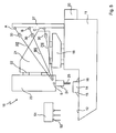
- Fig. 1 is a schematic side view of a machine tool 10 is shown, which is designed as a vertical traveling column machine.
- the new machine tool can also be present as a horizontal traveling column machine, in gantry design or in one of the other conventional designs, the vertical traveling column machine is used here only to illustrate the invention.
- the machine tool 10 comprises a subframe 11, which may be made of a stiffened framework or polymer concrete.
- a schematically indicated workpiece table 12 is formed as a workpiece carrier, on which in Fig. 1 a workpiece 14 can be seen, which is clamped over clamping means 15 and 16 on the workpiece table 12.
- an x-slide 18 is arranged via linear guides 17, which can zoom in or out of the drawing plane of the figure, which corresponds to the x-axis of the machine tool 10.
- stator 21 can be moved transversely to the x-direction, ie in the y-direction, relative to the base 11.
- the stand 21 carries at its front guides 22, on which a headstock 23 can be moved transversely to the x-direction and transversely to the y-direction, ie in the z-direction relative to the base 11.
- the headstock 23 carries in known manner a rotary-driven main spindle 24, which serves as a tool carrier and in which a tool 25 for machining the workpiece 14 is clamped.
- Linear guides 17, x-carriages 18, guide shoes 19, stator 21, guides 22 and headstock 23 are design elements that are provided with their own drives and linear scales or other measuring systems to specifically with the aid of an indicated at 20 machine control the tool carrier relative to the workpiece carrier method and to be able to control the position of the respective structural element.
- the tool 25 can be moved relative to the workpiece 14 in three mutually orthogonal axes, as shown by an indicated at 26 coordinate system.
- the coordinate system 26 defines a coordinate origin K, relative to which the position of the workpiece 14 is known and the position of the tool 25 is under the control of the machine control 20 respectively via the construction elements 18, 21, 23 currently approached.
- thermal displacements now occur, as already mentioned at the beginning. These thermal displacements cause the target position of the tool 25 to deviate from the actual coordinate position to the coordinate origin K, so that the machining of the workpiece 14 can not be done with the required accuracy and repeatability.
- the machine tool 10 has, in addition to the construction elements 18, 21, 23, a further, separate measuring system with two length measuring systems with which the distances between a tool-close measuring point S and two further measuring points A and B can be determined ,
- the tool-near measuring point S on the headstock 23 is located directly where the main spindle 24 exits from the headstock 23 down.
- the measuring point S is located as close as possible to the tool 25, so that the current position of the measuring point S corresponds to the position of the tool 25 or from which the position of the tool 25 can be derived.
- the measuring points A and B are provided on a machine plate formed as a rigid plate 27, which is rigidly but thermally decoupled by an angle 28 on the x-carriage 18 is attached. In this way, the measuring points A and B travel along with the x-slide 18, but do not share its thermal "shifting fate".
- Fig. 1 at 30 only indicated length measuring systems is now the distance AS between the measuring point S and the measuring point A and the distance BS determined between the measuring point S and the measuring point B.
- the two length measuring systems 30 are attached to the plate 27 so that they are outside the working range of the tool 25.
- the distance between the measuring point A and the measuring point B is known, it can be determined from the measured lengths AS and BS the relative position of the measuring point S to the measuring point A can be determined. Since the relative position of the measuring point A to the coordinate origin K is also known, the relative position of the measuring point S to the coordinate origin K can be determined in this way, as it is now based on Fig. 2 briefly to be discussed.
- Fig. 2 The geometric relationship between the measuring point S, the two measuring points A and B and the coordinate origin K is shown schematically above.
- the measuring point S and the measuring points A and B span, together with an imaginary point R, two right-angled triangles, whose adjoining y is the same for both triangles, while the counter-catheter z is at the known distance FROM different.
- Fig. 2 the relative position of the measuring point A as well as of the measuring point S to the coordinate origin K is also shown.
- This relative position corresponds to the actual actual position of the measuring point S, which can now be compared with the setpoint position specified by the control and used to determine correction values, which the control then takes into account in the further process.
- the length measuring system 30 uses a thread or wire 29 which is attached to the measuring point S and is deflected over the measuring point A, so that it comes to a spring 31, which tightens the thread 29 taut.
- the spring 31 expands or contracts accordingly.
- the thread or wire 29 is made of a length-invariant material such as Invar or Kevlar, so that it does not change in terms of its length neither in tension nor in temperature changes.
- a measuring pointer 32 which cooperates with a scale 33, is arranged on the thread or wire 29.
- the linear distance between the measuring points S and A can now be determined with the help of the linear scale 33, although the entire length of the thread or wire 29 between the measuring point S and the measuring pointer 32 is known.
- Measuring pointer 32 and length scale 33 together form a linear measuring system.
- linear measuring systems are optical measuring systems in question, using a steel or glass scale, linear potentiometers, which are operated as a voltage divider, inductive displacement transducer, in which a metallic plunger runs in a coil package, magnetic tape sensors in which a magnetic tape scanned with high-resolution magnetic structuring and, for example, laser distance meters.
- the linear measuring system 34 is arranged outside the working space.
- the measuring point and deflection point A and the length of the thread or wire 29 between the deflection point A and the measuring pointer 32 allows any positioning of the linear measuring system 34.
- FIG. 4 Another length measuring system is in Fig. 4 shown.
- This length measuring system uses a so-called pull-wire sensor 46, which measures the length of the already Fig. 3 known thread or wire 29 determined.
- the cable pull sensor 46 is also commercially available, it comprises a drum 47, on which the thread or wire 29 is wound, and a torsion spring 48, over which the thread or wire 29 is tensioned. With the drum 47, a rotary encoder 49 is connected, which detects the rotation of the drum 47 when the measuring point S is moved.
- the linear distance between the measuring points S and A can thus be determined at any time.
- the position of the measuring point S is determined in the y / z plane, since the other measuring points A and B with the x-slide 18 ride. It has been found that these measurements are sufficient for the compensation of thermal displacements, because the machine tool is constructed symmetrically to the y / z plane. In other words, there are no tilting moments in the x-direction, wherein the travel accuracy in the x-direction is also more accurate than in the y- and z-direction, because the x-slide 18 is moved by a ball screw, which is compensated by a glass scale ,
- the in Fig. 1 shown measuring system can be extended by the fact that the plate 27 is not attached to the x-carriage 18 but on the base frame 11. Now, if the headstock 23 is moved relative to the lower frame 11, the distance between the measuring point S on the one hand and the measuring points A and B on the other hand changes in all three dimensions, so that a further unknown must be determined. This can be achieved by providing a third measuring point C, wherein the distance between the measuring point C and the measuring point S is determined via a third length measuring system 30 arranged on the plate 27.
- the measuring point C is thereby arranged on the plate 27 so that it does not lie in the plane spanned by the points A, B and S.
- the plate 27 with the measuring points A and B also - as in Fig. 1 - remain on the x-carriage 18, while the measuring point C is provided on a separate plate which is fixed to the base frame 11.
- the required geometric relationship is similar to that in Fig. 2 represented relationship, here the location of the distances AS . BS and CS in the room now for the calculation according to Fig. 2 be projected into the levels x / y, x / z and y / z.
- the machine tool 10 off Fig. 5 is equipped with a schematically indicated at 51 tool magazine, which also in the machine tool 10 off Fig. 1 can be provided.
- 51 replacement tools 52 are stored, which are replaced in a conventional manner, for example in the pick-up method or tool change arms, during operation against the tool 25.
- the position determination for each substitute tool 25, 52, or for the measuring point S can now be done on the one hand continuously, ie parallel and simultaneously to control the machine tool 10 via the machine control 20. But it is also a sporadic determination of the actual position possible , ie only at certain times during the machining of a workpiece.
- the position determination via the length measuring systems 30 can also take place at certain positions during processing, if, for example, a particularly precise machining step has to be carried out. This increases the accuracy, e.g. in the position of a hole, and can also be used to determine the repeatability at certain points of the workpiece
Landscapes
- Engineering & Computer Science (AREA)
- Mechanical Engineering (AREA)
- Automatic Control Of Machine Tools (AREA)
Abstract
Description
Die vorliegende Erfindung betrifft ein Verfahren zur Bestimmung der Position eines Werkzeuges in einer Werkzeugmaschine, die einen Werkstückträger sowie einen über Konstruktionselemente relativ zu dem Werkstückträger und zu einem Maschinenteil verfahrbaren Werkzeugträger aufweist, in den das Werkzeug zur Bearbeitung eines von dem Werkstückträger getragenen Werkstückes eingespannt ist, wobei an dem Werkzeugträger ein werkzeugnaher Messpunkt und an dem Maschinenteil zumindest zwei weitere Messpunkte vorgesehen sind, die relative Position der weiteren Messpunkte zu einem Koordinatenursprungspunkt bekannt ist, und die Position des werkzeugnahen Messpunktes zu dem Koordinatenursprungspunkt bestimmt wird.The present invention relates to a method for determining the position of a tool in a machine tool, which has a workpiece carrier as well as a construction element movable relative to the workpiece carrier and a machine part tool carrier, in which the tool for machining a workpiece carried by the workpiece carrier workpiece is clamped, wherein a tool-near measuring point and on the machine part at least two further measuring points are provided on the tool carrier, the relative position of the other measuring points to a coordinate origin point is known, and the position of the tool-near measuring point is determined to the coordinate origin.
Die vorliegende Erfindung betrifft ferner eine Werkzeugmaschine, die einen Werkstückträger sowie einen über Konstruktionselemente relativ zu dem Werkstückträger und einem Maschinenteil verfahrbaren Werkzeugträger aufweist, in den ein Werkzeug zur Bearbeitung eines von dem Werkstückträger getragenen Werkstückes eingespannt ist.The present invention further relates to a machine tool, which has a workpiece carrier as well as a tool carrier which can be moved relative to the workpiece carrier and a machine part via construction elements, into which a tool for processing a workpiece carried by the workpiece carrier is clamped.
Derartige Verfahren und Werkzeugmaschinen sind beispielsweise aus der
Beide Druckschriften beschreiben Werkzeugmaschinen, bei denen ein auch Spindelstock genannter Spindelkopf über Konstruktionselemente in Form von Koppelgetrieben in einer Ebene relativ zu einem Werkstückträger verfahren wird. Die Koppelgetriebe sind mit einem Längenmaßstab verbunden, über den die Lage des jeweiligen Konstruktionselementes gemessen wird, um die Spindelköpfe während der Bearbeitung positionieren zu können.Both documents describe machine tools in which a spindle head also called spindle head is moved over construction elements in the form of coupling gears in a plane relative to a workpiece carrier. The coupling gears are connected to a linear scale, via which the position of the respective structural element is measured in order to position the spindle heads during processing can.
Das jeweilige Messsystem ist bei beiden bekannten Werkzeugmaschinen unmittelbar im Arbeitsraum der Werkzeugmaschine angeordnet und den dort vorherrschenden Verschmutzungen ausgesetzt.
Aus der
Aus der
Die
Die
From the
From the
The
The
Bei einem aus der
Auch dieses Verfahren wird auf einer Werkzeugmaschine durchgeführt, bei der das Messsystem unmittelbar im Arbeitsraum angeordnet ist.This method is also carried out on a machine tool, in which the measuring system is arranged directly in the working space.
Bei allen insoweit beschriebenen Verfahren und Werkzeugmaschinen ist von Nachteil, dass das Messsystem im Arbeitsraum angeordnet ist, wo es den Verschmutzungen durch die spanabhebende Bearbeitung sowie das Kühlschmiermittel ausgesetzt ist. Bei der Werkzeugmaschine aus der
Bei den bekannten Werkzeugmaschinen wird die Genauigkeit der Bearbeitung insbesondere durch thermische Verlagerungen beeinflusst, die vor allem an der Hauptspindel und an dem Messsystem selbst auftreten. Hauptursache für diese thermischen Verlagerungen sind zum einen Ausdehnungen an Motoren, Kugelrollspindeln, Linearführungen sowie dem Hauptspindellager.In the case of the known machine tools, the accuracy of the machining is influenced, in particular, by thermal displacements which occur, above all, on the main spindle and on the measuring system itself. The main reasons for these thermal displacements are, on the one hand, expansions of motors, ball screws, linear guides and the main spindle bearing.
Zum anderen beeinflussen auch Verformungen durch ungleichmäßige Erwärmung unterschiedlicher Maschinenkomponenten die Bearbeitungsgenauigkeit.On the other hand, deformations due to uneven heating of different machine components also influence the machining accuracy.
Ursache für diese thermischen Verlagerungen sind interne und externe Wärmequellen, wobei den externen Wärmequellen durch temperierte Räume und Anordnung der Werkzeugmaschine so, dass sie nicht direkt der Sonne ausgesetzt sind, begegnet werden kann.Cause of these thermal shifts are internal and external heat sources, the external heat sources through temperate spaces and arrangement of the machine tool so that they are not directly exposed to the sun, can be met.
Die internen Wärmequellen sind im Wesentlichen die wärmeerzeugenden Maschinenkomponenten, deren Eigenerwärmung sich bis zum Erreichen der Betriebstemperatur unterschiedlich auswirken kann. Hierzu zählen die Spindelrotation, interne Reibungen und vor allem auch der Zerspanungsprozess selbst sowie die dabei entstehenden heißen Metallspäne und das zugeführte Kühlschmiermittel.The internal heat sources are essentially the heat-generating machine components whose self-heating can have different effects until the operating temperature is reached. These include spindle rotation, internal friction and, above all, the cutting process itself, as well as the resulting hot metal chips and the supplied cooling lubricant.
All diese Faktoren beeinflussen das thermische Verhalten der Werkzeugmaschine und müssen reduziert werden, um entsprechende Bearbeitungsgenauigkeiten zu erzielen.All these factors influence the thermal behavior of the machine tool and must be reduced in order to achieve appropriate machining accuracies.
Diese Faktoren können dabei entweder konstruktiv reduziert oder steuerungstechnisch kompensiert werden, wozu direkte und indirekte Verfahren verwendet werden.These factors can either be reduced in terms of design or compensated by control technology, for which purpose direct and indirect methods are used.
Ein Beispiel für die konstruktive Reduzierung der durch das thermische Verhalten bedingten Genauigkeitsprobleme ist in der
Bei der direkten Kompensation wird die tatsächliche, also die Ist-Position der Hauptspindel über ein gesondertes Messsystem gemessen und mit der durch die Steuerung jeweils aktuell vorgegebenen Soll-Position verglichen. Die ermittelte Abweichung wird in der Steuerung verwendet, um die Wegsteuerbefehle zu korrigieren.In the case of direct compensation, the actual, that is to say the actual position of the main spindle is measured by means of a separate measuring system and compared with the target position which is currently preset by the controller. The determined deviation is used in the controller to correct the path control commands.
Ein derartiges Verfahren ist beispielsweise aus der eingangs erwähnten
Dieses Verfahren ist zwar sehr genau, für den Messvorgang muss jedoch der Fertigungsprozess unterbrochen werden, die Messung erfolgt also nicht hauptzeitparallel. Als weiteres Problem ist anzusehen, dass eine Unterbrechung des Fertigungsprozesses bei bestimmten Fertigungsschritten nicht möglich ist. Sofern diese Fertigungsschritte lange andauern, kann während dieser Zeitspanne keine Kompensation erfolgen.Although this method is very accurate, the measuring process must be interrupted for the production process, so the measurement does not take place parallel to the peak time. Another problem is that an interruption of the manufacturing process in certain manufacturing steps is not possible. If these manufacturing steps take a long time, no compensation can be made during this period.
Bei der indirekten Konzentration werden die thermisch bedingten Abweichungen in der Position der Hauptspindel zu dem Werkstück mit Hilfe eines mathematischen Modells aus gemessenen Hilfsgrößen wie der Temperatur an verschiedenen Punkten in der Werkzeugmaschine berechnet und in der Steuerung zur Kompensation verwendet.In the indirect concentration, the thermally induced deviations in the position of the main spindle to the workpiece by means of a mathematical model of measured auxiliary quantities such as the temperature at different Calculated points in the machine tool and used in the controller for compensation.
Dieses Verfahren ist beispielsweise aus der
Diese Messungen sind zwar hauptzeitparallel möglich, erfordern aber umfangreiche Messungen zur Ermittlung der Parameter, die in das mathematische Modell eingehen. Zudem bildet das mathematische Modell den tatsächlichen Betriebszustand häufig nur unvollständig ab, so dass diese Verfahren nicht so genau sind wie die oben erwähnte direkte Kompensation.Although these measurements are possible parallel to the main time, they require extensive measurements to determine the parameters that are included in the mathematical model. In addition, the mathematical model often incompletely maps the actual operating state, so that these methods are not as accurate as the above-mentioned direct compensation.
Die wesentlichen Nachteile des insoweit beschriebenen Standes der Technik liegen also darin, dass zum einen die Messsysteme den Verschmutzungen und sonstigen Belastungen des Arbeitsraumes ausgesetzt sind, wobei die Messungen häufig auch nicht hauptzeitparallel erfolgen können.The main disadvantages of the state of the art described so far are therefore that on the one hand, the measuring systems are exposed to contamination and other stresses of the working space, the measurements often can not be done parallel to the main time.
All dies führt dazu, dass nach wie vor ein Bedarf an neuen Werkzeugmaschinen und neuen Verfahren besteht, um die Position des Werkzeuges relativ zu dem Werkstück genau bestimmen zu können, ohne dass thermische Verlagerungen diese Genauigkeit beeinflussen.All this means that there is still a need for new machine tools and new methods to accurately determine the position of the tool relative to the workpiece without thermal shifts affecting this accuracy.
Vor diesem Hintergrund liegt der vorliegenden Erfindung die Aufgabe zugrunde, die eingangs genannten Verfahren sowie die eingangs genannte Werkzeugmaschine derart weiterzubilden, dass bei geringem konstruktivem Aufwand eine zuverlässige, schnelle Positionsbestimmung für den Werkzeugträger möglich wird, die hauptzeitparallel durchgeführt werden und in bestehende Werkzeugmaschinen nachgerüstet werden kann.Against this background, the present invention has the object, the above-mentioned method and the aforementioned machine tool in such a way that with low design effort reliable, rapid position determination for the tool carrier is possible, which are performed parallel to the main time and can be retrofitted into existing machine tools ,
Bei dem eingangs genannten Verfahren zur Bestimmung der Position eines Werkzeuges wird diese Aufgabe dadurch gelöst, dass mit Hilfe von zumindest zwei Längenmesssystemen, der lineare Abstand zwischen dem werkzeugnahen Messpunkt und jedem der weiteren Messpunkte gemessen und aus diesen Abständen sowie der bekannten relativen Position der weiteren Messpunkte die Position des werkzeugnahen Messpunktes zu dem Koordinatenursprungspunkt bestimmt wird, und zumindest einem Längenmesssystem ein Fadenelement zugeordnet ist, das an dem werkzeugnahen Messpunkt festgelegt ist und sich zu dem jeweiligen weiteren Messpunkt erstreckt, wobei die sich jeweils ergebende Länge des Fadenelementes zwischen dem werkzeugnahen Messpunkt und dem jeweiligen weiteren Messpunkt gemessen wird, wobei vorzugsweise an dem weiteren Messpunkt das Fadenelement umgelenkt und zu dem Längenmesssystem geführt wird.In the aforementioned method for determining the position of a tool, this object is achieved in that by means of at least two length measuring systems, the linear distance between the tool-near measuring point and each of the other measuring points measured and from these distances and the known relative position of the other measuring points, the position of the tool-near measuring point to the coordinate origin point is determined, and at least one length measuring system is associated with a thread element, the the tool-near measuring point is determined and extends to the respective further measuring point, wherein each resulting length of the thread element between the tool-near measuring point and the respective other measuring point is measured, preferably at the other measuring point, the thread element is deflected and guided to the length measuring system.
Bei der eingangs genannten Werkzeugmaschine wird diese Aufgabe dadurch gelöst, dass zumindest zwei Längenmesssysteme vorgesehen sind, die unmittelbar den linearen Abstand zwischen einem werkzeugnahen Messpunkt an dem Werkzeugträger und je einem weiteren Messpunkt an dem Maschinenteil erfassen, und zumindest einem Längenmesssystem ein Fadenelement zugeordnet ist, das an dem werkzeugnahen Messpunkt festgelegt ist und sich zu dem jeweiligen weiteren Messpunkt erstreckt, wobei die sich jeweils ergebende Länge des Fadenelementes zwischen dem werkzeugnahen Messpunkt und dem jeweiligen weiteren Messpunkt gemessen wird, wobei vorzugsweise an dem weiteren Messpunkt das Fadenelement umgelenkt und zu dem Längenmesssystem geführt wird.
Durch die Verwendung eines Fadens oder Drahtes, vorzugsweise eines dehnungsarmen Drahtes aus Invar oder Kevlar, kann der Maßstab außerhalb des Arbeitsraumes liegen, so dass weit weg vom Spanungsgeschehen gemessen werden kann. Der Draht wird dabei beispielsweise durch eine Feder auf Spannung gehalten.In the case of the machine tool mentioned at the outset, this object is achieved in that at least two length measuring systems are provided which directly detect the linear distance between a tool-near measuring point on the tool carrier and a further measuring point on the machine part, and at least one length measuring system is assigned a thread element which is determined at the tool-near measuring point and extends to the respective further measuring point, wherein each resulting length of the thread element between the tool-near measuring point and the respective other measuring point is measured, preferably at the other measuring point, the thread element is deflected and guided to the length measuring system ,
By using a thread or wire, preferably a low-expansion wire of Invar or Kevlar, the scale can be outside the working space, so that far away from the stress can be measured. The wire is held by tension, for example by a spring.
Die Erfinder der vorliegenden Anmeldung haben nämlich erkannt, dass das Hauptproblem im Stand der Technik darin besteht, dass dort mit den Längenmesssystemen die Korrekturwerte ermittelt werden, mit denen die Steuerung auch ansonsten arbeitet. Ein weiteres Problem besteht nach Erkenntnis der Erfinder darin, dass die Messung nicht an einem werkzeugnahen Punkt sondern entweder an den Führungen oder an verschiedenen Punkten am Spindelkopf erfolgt, was nicht mit hinreichender Genauigkeit möglich ist.Namely, the inventors of the present application have recognized that the main problem in the prior art is that the length measurement systems there determine the correction values with which the controller also works otherwise. Another problem, according to the inventors, is that that the measurement is not made on a tool-near point but either on the guides or at various points on the spindle head, which is not possible with sufficient accuracy.
Erfindungsgemäß wird nun die Position des Werkzeuges relativ zu einem Maschinenteil, das beispielsweise der x-Schlitten sein kann, dadurch bestimmt, dass mit einem gesonderten Messsystem der Abstand zwischen einem Punkt nahe am Werkzeug und zwei voneinander getrennten Punkten an dem Maschinenteil gemessen wird. Diese Messung erfolgt mit Hilfe von Längenmesssystemen, die von den Konstruktionselementen verschieden sind, was zu einer Entkopplung der Messung einerseits und der Steuerung der Verfahrwege des Werkzeuges andererseits führt.According to the invention, the position of the tool relative to a machine part, which can be, for example, the x-slide, is determined by measuring the distance between a point close to the tool and two separate points on the machine part with a separate measuring system. This measurement is carried out by means of length measuring systems, which are different from the construction elements, resulting in a decoupling of the measurement on the one hand and the control of the travel paths of the tool on the other.
Unter einem "Längenmesssystem wird im Rahmen der vorliegenden Erfindung ein Messsystem verstanden, das den kürzesten Abstand zwischen zwei Punkten im Raum misst, also sozusagen die Länge der Luftlinie zwischen diesen beiden Punkten.In the context of the present invention, a "length measuring system" is understood as meaning a measuring system which has the shortest distance between two Measures points in space, so to speak, the length of the straight line between these two points.
Unter einem "werkzeugnahen Messpunkt" wird im Rahmen der vorliegenden Anmeldung ein Messpunkt verstanden, der geometrisch so nahe bei dem Werkzeug liegt, und nur minimalen, vorzugsweise keinen thermischen Verlagerungen gegenüber dem Werkzeug bzw. dem Werkzeugträger ausgesetzt ist, so dass eine feste Beziehung zwischen der Position der Messpunktes und der Position des Werkzeuges besteht. Dieser Messpunkt kann an der Hauptspindel oder unmittelbar dort vorgesehen sein, wo die Hauptspindel aus dem sie tragenden Konstruktionselement austritt.In the context of the present application, a "measuring point close to the tooling" is understood to mean a measuring point which is geometrically so close to the tool and exposed to minimal, preferably no thermal displacements with respect to the tool or the tool carrier, so that a fixed relationship exists between the tool Position of the measuring point and the position of the tool exists. This measuring point can be provided on the main spindle or directly where the main spindle exits from the structural element carrying it.
Wenn die Position der beiden weiteren Messpunkte relativ zu dem Koordinatenursprung bekannt ist, kann die Lage des Messpunktes im Raum bestimmt und daraus die Verlagerung des Werkzeuges gegenüber dem Werkstück bzw. dem das Werkstück tragenden Werkstückträger bestimmt werden.If the position of the two further measuring points relative to the origin of coordinates is known, the position of the measuring point in space can be determined and from this the displacement of the tool relative to the workpiece or the workpiece carrier carrying the workpiece can be determined.
Ein besonderer Vorteil bei dem neuen Verfahren liegt darin, dass der Abstand zwischen den beiden weiteren Messpunkten sowie einem Punkt bestimmt wird, der nahe am Werkzeug liegt, wo der Verfahrweg ein anderer ist als unmittelbar an den Führungen, wo Systeme im Stand der Technik messen.A particular advantage of the new method is that it determines the distance between the other two measurement points and a point close to the tool where the travel is different than directly to the guides where systems in the prior art measure.
Ein weiterer Vorteil ist darin zu sehen, dass im Arbeitsraum vorhandene Verschmutzungen nicht die Probleme bereiten, wie sie bei Laserlichtschranken anzutreffen sind.Another advantage is the fact that present in the workspace soiling does not cause the problems that are encountered in laser light barriers.
Die beiden Messpunkte können dabei so an dem Maschinenteil angeordnet werden, dass sie das mögliche Verlagerungsschicksal dieses Maschinenteiles nicht teilen. Die beiden Messpunkte können z.B. auf einer steifen Platte angeordnet sein, die thermisch entkoppelt und spannungsfrei beispielsweise an dem x-Schlitten oder auch an dem Untergestell selbst befestigt ist.The two measuring points can be arranged on the machine part so that they do not share the possible Verlageungsschicksal this machine part. The two measuring points can be arranged for example on a rigid plate, which is thermally decoupled and tension-free, for example, attached to the x-slide or to the base itself.
Wichtig ist hier vor allem, dass der Abstand der beiden Messpunkte zueinander und die absolute Position zumindest eines dieser Messpunkte bekannt ist und durch das thermische Verhalten der Werkzeugmaschine selbst nicht verändert wird.It is important above all that the distance of the two measuring points from each other and the absolute position of at least one of these measuring points is known and is not changed by the thermal behavior of the machine tool itself.
Das neue Verfahren wird somit unabhängig von der Steuerung durchgeführt, es ersetzt die Steuerung nicht, sondern dient nur zur Kompensation von Verlagerungen, wobei es auch eingesetzt werden kann, um Verlagerungen nach einem Crash zu bestimmen.The new method is thus carried out independently of the control, it does not replace the control, but serves only to compensate for displacements, and it can also be used to determine displacements after a crash.
Das neue Verfahren und die neue Werkzeugmaschine ermöglichen es erstmals, kontinuierlich oder sporadisch oder zu bestimmten Zeitpunkten während der Bearbeitung eines Werkstückes über ein gesondertes Messsystem die Ist-Position des Werkzeuges unabhängig von den Konstruktionselementen zu bestimmen, über die der Werkzeugträger relativ zu dem Werkstückträger verfahren wird.The new method and the new machine tool make it possible for the first time, continuously or sporadically or at certain times during the machining of a workpiece via a separate measuring system, to determine the actual position of the tool independently of the construction elements over which the tool carrier is moved relative to the workpiece carrier ,
Das Verfahren kann als zusätzliche Kontrolle für die Position des Werkzeugträgers verwendet und kontinuierlich durchgeführt werden, wobei es auch dazu verwendet werden kann, die Werkzeugmaschine zu führen, also die übliche Maschinensteuerung zu ergänzen oder zu überwachen.The method can be used as an additional control for the position of the tool carrier and carried out continuously, and it can also be used to run the machine tool, so to supplement or monitor the usual machine control.
Das Verfahren kann aber auch nur zu bestimmten Zeitpunkten durchgeführt werden, wenn beispielsweise an einer bestimmten Positionen während der Bearbeitung ein besonders genauer Bearbeitungsschritt durchgeführt werden muss. Das erhöht die Genauigkeit, z.B. der Position einer Bohrung, und kann auch verwendet werden, um die Wiederholgenauigkeit an bestimmten Punkten des Werkstückes zu bestimmen oder zu optimieren.However, the method can also be carried out only at certain points in time, if, for example, a particularly precise machining step has to be carried out at a specific position during machining. This increases the accuracy, e.g. The position of a hole, and can also be used to determine or optimize the repeatability at certain points of the workpiece.
Es kann aber auch während eines automatischen Werkzeugwechsels durchgeführt werden, um immer zu diesen Zeitpunkten die Werkzeugmaschine auf Verlagerungen hin zu überprüfen, die sich durch thermische Ausdehnungen oder Lastveränderungen ergeben, und die Folgen derartiger Verlagerungen zu kompensieren.However, it can also be carried out during an automatic tool change in order to always check the machine tool for displacements at those times, which are due to thermal expansions or Load changes and to compensate for the consequences of such relocations.
Die dabei verwendeten Längenmesssysteme liegen ferner nicht im Kraftfluss der Werkzeugmaschine, sind also losgelöst vom Kraftübertragungssystem der Werkzeugmaschine, was die Messgenauigkeit erhöht.The length measuring systems used in this case are also not in the power flow of the machine tool, so are detached from the power transmission system of the machine tool, which increases the accuracy of measurement.
Die der Erfindung zugrunde liegende Aufgabe wird auf diese Weise daher vollständig gelöst.The object underlying the invention is therefore completely solved in this way.
Wenn nur zu bestimmten Zeitpunkten die Position des werkzeugnahen Messpunktes bestimmt wird, beispielsweise auch beim Werkzeugwechsel, müssen lediglich kleine Abweichungen vom Soll-Wert erfasst werden, was eine einfache Messung und Mathematik und damit eine schnelle Erfassung der Abweichungen zwischen Soll-Wert und Ist-Wert ermöglicht.If only at certain times the position of the tool-near measuring point is determined, for example, during the tool change, only small deviations from the target value must be detected, which is a simple measurement and mathematics and thus a quick detection of deviations between target value and actual value allows.
Das neue Verfahren wird besonders vorteilhaft eingesetzt, um thermische Verlagerungen erkennen und kompensieren zu können. Dabei handelt es sich um ein direktes Kompensationsverfahren, da die Ist-Position direkt gemessen wird, was zu einer hohen Genauigkeit führt.The new method is used particularly advantageously in order to detect and compensate for thermal displacements. This is a direct compensation method because the actual position is measured directly, resulting in high accuracy.
Das Verfahren wird dabei unabhängig von der üblichen Verfahrmechanik durchgeführt und erfolgt wegen der gesonderten Längenmesssysteme hauptzeitparallel.The process is carried out independently of the usual traversing mechanism and takes place parallel to the main time due to the separate length measuring systems.
Vor diesem Hintergrund betrifft die vorliegende Erfindung auch ein Verfahren zur Bestimmung von Verlagerungen, bspw. infolge thermischer Ausdehnungen oder Lastveränderungen, bei einer Werkzeugmaschine, die einen Werkstückträger sowie einen über Konstruktionselemente relativ zu dem Werkstückträger und einem Maschinenteil verfahrbaren Werkzeugträger aufweist, in den ein Werkzeug zur Bearbeitung eines von dem Werkstückträger getragenen Werkstückes eingespannt ist, bei dem zu bestimmten Zeitpunkten während der Bearbeitung des Werkstückes die Position des Werkzeugträgers gemäß dem neuen Verfahren bestimmt und die so bestimmte Ist-Position mit einer Soll-Position verglichen wird, wobei vorzugsweise zu den bestimmten Zeitpunkten ein Werkzeugwechsel durchgeführt oder ein Bearbeitungsvorgang, bspw. eine Bohrung, begonnen wird.Against this background, the present invention also relates to a method for determining displacements, for example due to thermal expansion or load changes, in a machine tool having a workpiece carrier and a relative to the workpiece carrier and a machine part movable tool carrier via construction elements, in which a tool for Machining a workpiece carried by the workpiece carrier is clamped, in which determines the position of the tool carrier according to the new method at certain times during machining of the workpiece and the thus determined actual position is compared with a desired position, preferably performed at the specific times a tool change or a machining operation, eg Drilling, is started.
Die der Erfindung zugrunde liegende Aufgabe wird auch auf diese Weise vollständig gelöst.The object underlying the invention is also completely solved in this way.
Dabei ist es bevorzugt. wenn der Werkzeugträger in einer durch die Messpunkte aufgespannten Ebene relativ zu dem Maschinenteil verfahrbar ist, wobei vorzugsweise der Werkzeugträger zusammen mit dem Maschinenteil senkrecht zu der durch die Messpunkte aufgespannten Ebene relativ zu dem Werkstückträger verfahrbar ist und zwei Längenmesssysteme vorgesehen sind.It is preferred. when the tool carrier is movable in a plane spanned by the measuring points relative to the machine part, wherein preferably the tool carrier is movable together with the machine part perpendicular to the plane defined by the measuring points plane relative to the workpiece carrier and two length measuring systems are provided.
Bei dieser Maßnahme ist von Vorteil, dass sich die Ist-Position mit einfachen mathematischen Formeln beschreiben und folglich schnell berechnen lässt. Die beiden weiteren Messpunkte werden dann z.B. bei einer Fahrständermaschine am x-Schlitten angeordnet, indem dort das Maschinenteil z.B. thermisch entkoppelt befestigt wird. Damit wird die Ist-Position in der y/z-Ebene bestimmt, was für die meisten Anwendungsfälle ausreicht.In this measure, it is advantageous that the actual position can be described using simple mathematical formulas and therefore can be calculated quickly. The two further measuring points are then sent e.g. in a traveling column machine arranged on the x-slide, by there the machine part, e.g. thermally decoupled attached. This determines the actual position in the y / z plane, which is sufficient for most applications.
Alternativ ist es bevorzugt, wenn das Maschinenteil gegenüber dem Werkstückträger unverschieblich an der Werkzeugmaschine angeordnet ist und drei Längenmesssysteme vorgesehen sind.Alternatively, it is preferred if the machine part is arranged immovably relative to the workpiece carrier on the machine tool and three length measuring systems are provided.
Wenn die Längenmesssysteme nicht mitfahren, wird ein dritter Abstand benötigt, wozu das Maschineteil im Falle einer Fahrständermaschine am Untergestell angeordnet werden kann.If the length measuring systems do not ride along, a third distance is required, for which purpose the machine part can be arranged on the underframe in the case of a traveling column machine.
Insgesamt ist es bevorzugt, wenn der Werkzeugträger relativ zu dem Werkstückträger in drei orthogonalen Achsen jeweils linear verfahrbar ist.Overall, it is preferred if the tool carrier is in each case linearly displaceable relative to the workpiece carrier in three orthogonal axes.
Dies führt für das Verfahren des Werkzeuges zu einer seriellen Kinematik, beispielsweise einer Fahrständermaschine, bei der die Achsen aufeinander aufbauen. Getrennt davon gibt es die Längenmesssysteme für die parallelkinematische Positionsmessung, die voneinander entkoppelt sind.This leads to the process of the tool to a serial kinematics, such as a traveling column machine, in which the axes build on each other. Separately, there are the length measuring systems for the parallel kinematic position measurement, which are decoupled from each other.
Dabei ist es bevorzugt, wenn die Längenmesssysteme zumindest teilweise an dem Maschinenteil angeordnet sind.It is preferred if the length measuring systems are arranged at least partially on the machine part.
Diese Maßnahme ist konstruktiv von Vorteil, denn es müssen keine gesonderten Montagestellen für die Längenmesssysteme bereitgestellt werden. Damit könne auch bestehende Werkzeugmaschine erfindungsgemäß umgerüstet oder nachgerüstet werden.This measure is structurally advantageous, because there is no need to provide separate mounting points for the length measuring systems. This could also be converted or retrofitted existing machine tool according to the invention.
Schließlich ist es bevorzugt, wenn zumindest ein Längenmesssystem einen Seilzugsensor umfasst.Finally, it is preferred if at least one length measuring system comprises a cable pull sensor.
Dies ist eine konstruktiv vorteilhafte Ausgestaltung der Längenmesssysteme, die kommerziell im Handel verfügbar sind.This is a structurally advantageous embodiment of the length measuring systems, which are commercially available commercially.
Dann ist es bevorzugt, wenn das Maschinenteil thermisch von der Werkzeugmaschine entkoppelt ist.Then it is preferred if the machine part is thermally decoupled from the machine tool.
Hier ist von Vorteil, dass der für die Messgenauigkeit entscheidende Abstand zwischen den weiteren Messpunkten (A, B, C) nicht das thermische Schicksal der Werkzeugmaschine teilt.Here, it is advantageous that the decisive difference in measurement accuracy between the other measuring points (A, B, C) does not share the thermal fate of the machine tool.
Weitere Vorteile ergeben sich aus der Beschreibung und der beigefügten Zeichnung.Further advantages will become apparent from the description and the accompanying drawings.
Es versteht sich, dass die vorstehend genannten und die nachstehend noch zu erläuternden Merkmale nicht nur in der jeweils angegebenen Kombination, sondern auch in anderen Kombinationen oder in Alleinstellung verwendbar sind, ohne den Rahmen der vorliegenden Erfindung zu verlassen.It is understood that the features mentioned above and those yet to be explained below can be used not only in the particular combination given, but also in other combinations or in isolation, without departing from the scope of the present invention.
Ein Ausführungsbeispiel der Erfindung ist in der Zeichnung dargestellt und wird in der nachfolgenden Beschreibung näher erläutert. Es zeigen:
- Fig. 1
- die neue Werkzeugmaschine in schematischer Seitenansicht, wobei ein Messpunkt nahe an dem Werkzeugträger und zwei weitere Messpunkte über ein Maschinenteil an dem x-Schlitten angeordnet sind;
- Fig. 2
- eine schematische Darstellung, wie bei der Werkzeugmaschine aus
Fig. 1 aus den gemessenen Abständen zwischen dem Messpunkt nahe an dem Werkzeugträger und den beiden weiteren Messpunkten die relative Lage des Messpunktes S zu dem Koordinatenursprung bestimmt wird; - Fig. 3
- ein erstes Ausführungsbeispiel für ein Längenmesssystem, mit dem der Abstand zwischen dem Messpunkt S und dem Messpunkt A bestimmt wird;
- Fig. 4
- ein weiteres Ausführungsbeispiel für das Längenmesssystem; und
- Fig. 5
- eine Darstellung wie
Fig. 1 , wobei jedoch drei weitere Messpunkte an dem Maschinenteil angeordnet sind, das jetzt an dem Untergestellt befestigt ist.
- Fig. 1
- the new machine tool in a schematic side view, wherein a measuring point close to the tool carrier and two other measuring points are arranged on a machine part of the x-carriage;
- Fig. 2
- a schematic representation, as in the machine tool
Fig. 1 from the measured distances between the measuring point close to the tool carrier and the other two measuring points, the relative position of the measuring point S to the coordinate origin is determined; - Fig. 3
- a first embodiment of a length measuring system, with which the distance between the measuring point S and the measuring point A is determined;
- Fig. 4
- a further embodiment of the length measuring system; and
- Fig. 5
- a representation like
Fig. 1 However, with three other measuring points are arranged on the machine part, which is now attached to the lower part.
In
Die Werkzeugmaschine 10 umfasst ein Untergestell 11, das aus einem versteiften Stabwerk oder Polymerbeton gefertigt sein kann. An dem Untergestell 11 ist als Werkstückträger ein schematisch angedeuteter Werkstücktisch 12 ausgebildet, auf dem in
An dem Untergestell 11 ist über Linearführungen 17 ein x-Schlitten 18 angeordnet, der in die Zeichenebene der Figur hinein- bzw. aus ihr herausfahren kann, was der x-Achse der Werkzeugmaschine 10 entspricht.On the
Auf dem x-Schlitten 18 sind Führungsschuhe 19 angeordnet, in denen ein Ständer 21 quer zu der x-Richtung, also in y-Richtung, gegenüber dem Untergestell 11 verfahren werden kann.On the x-slide 18
Der Ständer 21 trägt an seiner Vorderseite Führungen 22, an denen ein Spindelstock 23 quer zur x-Richtung sowie quer zur y-Richtung, also in z-Richtung relativ zu dem Untergestell 11 verfahren werden kann.The
Der Spindelstock 23 trägt in an sich bekannter Weise eine drehangetriebene Hauptspindel 24, die als Werkzeugträger dient und in die ein Werkzeug 25 zur Bearbeitung des Werkstückes 14 eingespannt ist.The
Linearführungen 17, x-Schlitten 18, Führungsschuhe 19, Ständer 21, Führungen 22 und Spindelstock 23 sind Konstruktionselemente, die mit eigenen Antrieben und Linearmaßstäben oder sonstigen Messsystemen versehen sind, um mit Hilfe einer bei 20 angedeuteten Maschinensteuerung den Werkzeugträger gegenüber dem Werkstückträger gezielt verfahren und die Position des jeweiligen Konstruktionselementes regeln zu können.Linear guides 17, x-carriages 18, guide shoes 19,
Auf die insoweit beschriebene Art und Weise kann also das Werkzeug 25 relativ zu dem Werkstück 14 in drei zueinander orthogonalen Achsen verfahren werden, wie es durch ein bei 26 angedeutetes Koordinatenkreuz gezeigt ist. Das Koordinatenkreuz 26 definiert einen Koordinatenursprungspunkt K, relativ zu dem die Position des Werkstückes 14 bekannt ist und die Position des Werkzeuges 25 unter der Kontrolle der Maschinensteuerung 20 jeweils über die Konstruktionselemente 18, 21, 23 aktuell angefahren wird.In the manner described so far, therefore, the
Im Betrieb der Werkzeugmaschine 10 kommt es nun zu thermischen Verlagerungen, wie sie eingangs bereits erwähnt wurden. Diese thermischen Verlagerungen führen dazu, dass die Soll-Position des Werkzeuges 25 zu dem Koordinatenursprungspunkt K von der tatsächlichen Ist-Position abweicht, so dass die Bearbeitung des Werkstückes 14 nicht mit der erforderlichen Genauigkeit und Wiederholbarkeit erfolgen kann.During operation of the
Um diese thermischen Verlagerungen kompensieren zu können, weist die Werkzeugmaschine 10 zusätzlich zu den Konstruktionselementen 18, 21, 23 ein weiteres, gesondertes Messsystem mit zwei Längenmesssystemen auf, mit denen die Abstände zwischen einem werkzeugnahen Messpunkt S und zwei weiteren Messpunkten A und B bestimmt werden können. Wie in
Die Messpunkte A und B sind an einem als steife Platte 27 ausgebildetem Maschinenteil vorgesehen, das über einen Winkel 28 steif aber thermisch entkoppelt an dem x-Schlitten 18 befestigt ist. Auf diese Weise fahren die Messpunkte A und B mit dem x-Schlitten 18 mit, teilen aber nicht sein thermisches "Verlagerungsschicksal".The measuring points A and B are provided on a machine plate formed as a
Über zwei, in
Da der Abstand zwischen dem Messpunkt A und dem Messpunkt B bekannt ist, kann anhand der gemessenen Längen
In
Der Messpunkt S und die Messpunkte A und B spannen zusammen mit einem imaginären Punkt R zwei rechtwinklige Dreiecke auf, deren Ankathete y für beide Dreiecke gleich ist, während die Gegenkathete z sich um den bekannten Abstand
Unten in
Damit handelt es sich um ein eindeutig bestimmtes geometrisches System, so dass die Strecken y und z berechnet werden können.This is a clearly defined geometric system so that the distances y and z can be calculated.
In
Da die relative Position des Messpunktes A zu dem Koordinatenursprungspunkt K bekannt ist, lässt sich nunmehr die relative Position des Messpunktes S zu dem Koordinatenursprungspunkt K durch die beiden unteren Gleichungen in
Diese relative Position entspricht der tatsächlichen Ist-Position des Messpunktes S, die nun mit der durch die Steuerung vorgegebenen Soll-Position verglichen und zur Bestimmung von Korrekturwerten verwendet werden kann, die die Steuerung dann beim weiteren Prozess berücksichtigt.This relative position corresponds to the actual actual position of the measuring point S, which can now be compared with the setpoint position specified by the control and used to determine correction values, which the control then takes into account in the further process.
Für die Bestimmung der Abstände
In
Der Faden oder Draht 29 ist aus einem längeninvarianten Material wie Invar oder Kevlar gefertigt, so dass er sich weder bei Zugbelastung noch bei Temperaturänderungen hinsichtlich seiner Länge verändert.The thread or
Zwischen dem Umlenkpunkt A und der Feder 31 ist an dem Faden oder Draht 29 ein Messzeiger 32 angeordnet, der mit einem Maßstab 33 zusammenwirkt. Bei Bewegung des Messpunktes S verfährt somit der Messzeiger 32 gegenüber dem Längenmaßstab 33. Wenn der Abstand des Maßstabes 33 von dem Messpunkt A bekannt ist, kann nun mit Hilfe des Längenmaßstabes 33 der lineare Abstand zwischen den Messpunkten S und A bestimmt werden, wenn auch die gesamte Länge des Fadens oder Drahtes 29 zwischen dem Messpunkt S und dem Messzeiger 32 bekannt ist.Between the deflection point A and the
Messzeiger 32 und Längenmaßstab 33 bilden zusammen ein lineares Messsystem. Für derartige lineare Messsysteme kommen optische Messsysteme in Frage, die einen Stahl- oder Glasmaßstab verwenden, Linearpotentiometer, die als Spannungsteiler betrieben werden, induktive Wegaufnehmer, bei denen ein metallischer Stößel in einem Spulenpaket läuft, Magnetbandsensoren, bei denen ein Magnetband mit hochauflösender magnetischer Strukturierung abgetastet wird, sowie beispielsweise Laserabstandsmesser.Measuring
Wichtig bei dem Linearmesssystem 34 ist dabei, dass es außerhalb des Arbeitsraumes angeordnet wird. Der Messpunkt und Umlenkpunkt A sowie die Länge des Fadens oder Drahtes 29 zwischen dem Umlenkpunkt A und dem Messzeiger 32 lässt eine beliebige Positionierung des Linearmesssystems 34 zu.Important in the case of the
Ein weiteres Längenmesssystem ist in
Der Seilzugsensor 46 ist auch kommerziell erhältlich, er umfasst eine Trommel 47, auf die der Faden oder Draht 29 aufgewickelt wird, sowie eine Torsionsfeder 48, über die der Faden oder Draht 29 gespannt wird. Mit der Trommel 47 ist ein Drehgeber 49 verbunden, der die Drehung der Trommel 47 erfasst, wenn der Messpunkt S bewegt wird.The
Wenn der Abstand zwischen dem Umlenkpunkt A und dem Seilzugsensor 46 sowie die Länge des Fadens oder Drahtes 29 bekannt sind, lässt sich somit jederzeit der lineare Abstand zwischen den Messpunkten S und A bestimmen.If the distance between the deflection point A and the
Bei der in
Sollte dennoch auch eine Kompensation in x-Richtung erforderlich sein, kann das in
Der Messpunkt C wird dabei so an der Platte 27 angeordnet, dass er nicht in der durch die Punkte A, B und S aufgespannten Ebene liegt. Alternativ kann die Platte 27 mit den Messpunkten A und B auch - wie in
Die dazu erforderliche geometrische Beziehung ähnelt der in
Aus Genauigkeitsgründen kann es erforderlich sein, die weiteren Messpunkte A, B und C nicht untereinander, also längs der x-Achse, anzuordnen, wie dies in Fig. 7 gezeigt ist, sondern beispielsweise zwei Messpunkte in z-Richtung zueinander auszurichten, wie es in
Die Werkzeugmaschine 10 aus
Die Positionsbestimmung für das jeweils eingewechselte Werkzeug 25, 52, bzw. für den Messpunkt S, kann nun einerseits kontinuierlich erfolgen, also parallel und zeitgleich zur Ansteuerung der Werkzugmaschine 10 über die Maschinensteuerung 20. Es ist aber auch eine sporadische Bestimmung der Ist-Position möglich, also nur zu bestimmten Zeitpunkten während der Bearbeitung eines Werkstückes.The position determination for each
Dies kann als zusätzliche Kontrolle für die Position des Werkzeugträgers verwendet werden, oder aber zu bestimmten Zeitpunkten durchgeführt werden, wenn beispielsweise ein Werkzeugwechsel erfolgt. Dann befindet sich die Hauptspindel i.d.R. in einer festgelegten Werkzeugübergabeposition, so dass die Messung schnell und einfach erfolgt und die Berechnung der Ist-Position mathematisch unproblematisch ist. Für viele Anwendungsfälle ist dies hinreichend.This can be used as additional control for the position of the tool carrier, or be performed at certain times, for example, when a tool change occurs. Then the main spindle i.d.R. in a fixed tool transfer position, so that the measurement is quick and easy and the calculation of the actual position is mathematically unproblematic. This is sufficient for many applications.
Die Positionsbestimmung über die Längenmesssysteme 30 kann aber auch an bestimmten Positionen während der Bearbeitung erfolgen, wenn bspw. ein besonders genauer Bearbeitungsschritt durchgeführt werden muss. Das erhöht die Genauigkeit, z.B. in der Position einer Bohrung, und kann auch verwendet werden, um die Wiederholgenauigkeit an bestimmten Punkten des Werkstückes zu bestimmen However, the position determination via the
Claims (14)
- A method for determining the position of a tool (25) in a machine tool (10) comprising a workpiece carrier (12) and a tool holder (24) movable relative to the workpiece carrier (12) and a machine part (27) via constructional elements (18, 21, 23), in which tool holder the tool (25) is clamped in for processing a workpiece (14) supported by the workpiece support (12), wherein
on the tool carrier (24) a near-to-tool measuring point (S) and on the machine part (27) at least two further measuring points (A, B, C) are provided,
the position of the further measurement points (A, B, C) relative to a coordinate origin (K) is known,
and the position of the near-to-tool measuring point (S) relative to the coordinate origin (K) is determined,
wherein by means of at least two length measurement systems (30) the linear distance
(AS BS CS ) between the near-to-tool measuring point (S) and each of the further measuring points (A, B, C) is measured, and wherein from these distances (AS BS CS ) and the known relative position of the further measurement points (A, B, C) the position of the near-to-tool measuring point (S) relative to the coordinate origin (K) is determined,
characterized in that at least one length measurement system (30) is associated with a thread element (29) which is attached to the near-to-tool measuring point (S) and extends to the respective further measuring point (A, B, C), the respectively resulting length of the thread element (29) between the near-to-tool measuring point (S) and the respective further measuring point (A, B, C) being measured. - Method according to claim 1, characterized in that the tool carrier (24) is movable relative to the machine part (27) in a plane (y, z) set up by the measuring points (S, A, B).
- Method according to claim 2, characterized in that together with the machine part (27) the tool carrier (24) is movable relative to the workpiece carrier (12) perpendicular (x) to the plane (y, z) set up by the measuring points (S, A, B), and that two length measurement systems (30) are provided.
- Method according to claim 1, characterized in that the machine part (27) is arranged on the machine tool (10) such as to be not displaceable relative to the workpiece carrier (12), and that three length measurement systems (30) are provided.
- Method according to any one of claims 1 to 4, characterized in that the tool carrier (24) is linearly movable in each of three orthogonal axes (x, y, z) relative to the workpiece carrier (12).
- A method for determining displacement, for example due to thermal expansion or change of load, in a machine tool (10) comprising a workpiece carrier (12) and a tool holder (24) movable relative to the workpiece carrier (12) and a machine part (27) via constructional elements (18, 21, 23), in which tool holder a tool (25) is clamped in for processing a workpiece (14) supported by the workpiece support (12),
wherein during the machining of the workpiece (14), the position of the tool carrier (24) is determined according to the method of any one of claims 1 to 5, and the real position thus determined is compared with a nominal position. - Method according to claim 6, characterized in that the position of the tool carrier is determined at certain points in time when for example a tool change is performed or a machining operation, for example a boring, is started.
- A machine tool comprising a workpiece carrier (12) and a tool holder (24) movable relative to the workpiece carrier (12) and a machine part (27) via constructional elements (18, 21, 23), in which tool holder a tool (25) is clamped in for processing a workpiece (14) supported by the workpiece support (12),
wherein at least two length measurement systems (30) are provided which directly measure the linear distance between a near-to-tool measuring point (S) on the tool carrier and each one further measuring point (A, B , C) on the machine part, characterized in that at least one length measurement system (30) is associated with a thread element (29) which is attached to the near-to-tool measuring point (S) and extends to the respective further measuring point (A, B, C), the respectively resulting length of the thread element (29) between the near-to-tool measuring point (S) and the respective further measuring point (A, B, C) being measured. - Machine tool according to claim 8, characterized in that together with the machine part (27) the tool carrier (24) is movable relative to the workpiece carrier (12) perpendicular (x) to the plane (y, z) set up by the measuring points (S, A, B), and that two length measurement systems (30) are provided.
- Machine tool according to claim 8, characterized in that the machine part (27) is arranged on the machine tool (10) such as to be not displaceable relative to the workpiece carrier (12), and that three length measurement systems (30) are provided.
- Machine tool according to any one of claims 8 to 10, characterized in that the length measurement systems (30) are at least partially arranged on the machine part (27).
- Machine tool according to any one of claims 8 to 11, characterized in that at least one length measurement system (30) comprises a cable sensor (45).
- Machine tool according to any one of claims 8 to 12, characterized in that at the further measuring point (A, B, C) the thread element (29) is deflected and guided to the length measurement system (34, 41, 45).
- Machine tool according to any one of claims 8 to 13, characterized in that the machine part (27) is thermally uncoupled from the machine tool (10).
Priority Applications (1)
| Application Number | Priority Date | Filing Date | Title |
|---|---|---|---|
| PL11701387T PL2365893T3 (en) | 2010-01-28 | 2011-01-20 | Method for determining the position of a tool |
Applications Claiming Priority (2)
| Application Number | Priority Date | Filing Date | Title |
|---|---|---|---|
| DE102010006504A DE102010006504B4 (en) | 2010-01-28 | 2010-01-28 | Method for determining the position of a tool |
| PCT/EP2011/050742 WO2011092104A1 (en) | 2010-01-28 | 2011-01-20 | Method for determining the position of a tool |
Publications (2)
| Publication Number | Publication Date |
|---|---|
| EP2365893A1 EP2365893A1 (en) | 2011-09-21 |
| EP2365893B1 true EP2365893B1 (en) | 2013-12-25 |
Family
ID=43821784
Family Applications (1)
| Application Number | Title | Priority Date | Filing Date |
|---|---|---|---|
| EP11701387.0A Active EP2365893B1 (en) | 2010-01-28 | 2011-01-20 | Method for determining the position of a tool |
Country Status (5)
| Country | Link |
|---|---|
| EP (1) | EP2365893B1 (en) |
| DE (1) | DE102010006504B4 (en) |
| ES (1) | ES2443877T3 (en) |
| PL (1) | PL2365893T3 (en) |
| WO (1) | WO2011092104A1 (en) |
Families Citing this family (6)
| Publication number | Priority date | Publication date | Assignee | Title |
|---|---|---|---|---|
| JP5719625B2 (en) * | 2010-07-26 | 2015-05-20 | Dmg森精機株式会社 | Machine Tools |
| DE102011013155A1 (en) * | 2011-02-28 | 2012-08-30 | Chiron-Werke Gmbh & Co Kg | machine tool |
| DE102013107791B4 (en) | 2013-07-22 | 2017-05-04 | Chiron-Werke Gmbh & Co. Kg | machine tool |
| DE102016213663A1 (en) * | 2016-07-26 | 2018-02-01 | Siemens Aktiengesellschaft | Method for controlling an end element of a machine tool and a machine tool |
| CN113432530A (en) * | 2021-05-27 | 2021-09-24 | 北京精雕科技集团有限公司 | Method and device for measuring positioning accuracy of tool magazine |
| CN113681637B (en) * | 2021-08-26 | 2022-10-25 | 广州弘高科技股份有限公司 | Punching equipment and method for circuit board testing needle bed |
Citations (2)
| Publication number | Priority date | Publication date | Assignee | Title |
|---|---|---|---|---|
| WO1997046925A1 (en) * | 1996-06-06 | 1997-12-11 | The Boeing Company | Method for improving the accuracy of machines |
| WO2005019769A1 (en) * | 2003-08-22 | 2005-03-03 | Bundesrepublik Deutschland Vertr. Durch Das Bundesminissterium Für Wirtschaft Und Arbeit Dieses Vertr. Durch Den Präsidenten Der Physikalisch-Technischen Bundesanstalt | Method for the determination of systematic geometric deviations in technical multi-body systems |
Family Cites Families (11)
| Publication number | Priority date | Publication date | Assignee | Title |
|---|---|---|---|---|
| DE3504464C1 (en) * | 1985-02-09 | 1986-04-17 | Fraunhofer-Gesellschaft zur Förderung der angewandten Forschung e.V., 8000 München | Transportable measuring instrument for testing the positional accuracy of a program-controlled appliance arm |
| JP3327655B2 (en) * | 1993-12-27 | 2002-09-24 | ブラザー工業株式会社 | NC machine tool displacement compensator |
| SE509505C2 (en) * | 1996-02-20 | 1999-02-01 | Neos Robotics Ab | Positioning method and positioning device for a production system |
| DE19743149A1 (en) * | 1997-09-30 | 1999-04-08 | Chiron Werke Gmbh | Machine tool |
| SE512338C2 (en) * | 1998-06-25 | 2000-02-28 | Neos Robotics Ab | System and method for controlling a robot |
| DE19853757C2 (en) * | 1998-11-21 | 2001-02-15 | Rolf Wissner | Measuring device for determining the position of a machine part |
| DE19947374B4 (en) * | 1999-10-01 | 2005-11-03 | Bundesrepublik Deutschland, vertr. d. d. Bundesministerium für Wirtschaft und Arbeit, dieses vertr. d. d. Präsidenten der Physikalisch-Technischen Bundesanstalt | Method for determining geometric deviations of coordinate measuring machines or machine tools |
| DE10330915B4 (en) * | 2003-07-04 | 2008-01-03 | Chiron-Werke Gmbh & Co Kg | Method for compensation of displacements |
| DE10343320A1 (en) * | 2003-09-10 | 2005-04-14 | Chiron-Werke Gmbh & Co Kg | Machine tool with two spindle housings and adjusting device for the position of the spindle housing to each other |
| DE102005000732A1 (en) * | 2005-01-04 | 2006-07-13 | Siemens Ag | Radio-based location system with synthetic aperture |
| DE102007041827B4 (en) * | 2007-09-03 | 2018-06-21 | Siemens Aktiengesellschaft | machine tool |
-
2010
- 2010-01-28 DE DE102010006504A patent/DE102010006504B4/en not_active Expired - Fee Related
-
2011
- 2011-01-20 WO PCT/EP2011/050742 patent/WO2011092104A1/en active Application Filing
- 2011-01-20 EP EP11701387.0A patent/EP2365893B1/en active Active
- 2011-01-20 PL PL11701387T patent/PL2365893T3/en unknown
- 2011-01-20 ES ES11701387.0T patent/ES2443877T3/en active Active
Patent Citations (2)
| Publication number | Priority date | Publication date | Assignee | Title |
|---|---|---|---|---|
| WO1997046925A1 (en) * | 1996-06-06 | 1997-12-11 | The Boeing Company | Method for improving the accuracy of machines |
| WO2005019769A1 (en) * | 2003-08-22 | 2005-03-03 | Bundesrepublik Deutschland Vertr. Durch Das Bundesminissterium Für Wirtschaft Und Arbeit Dieses Vertr. Durch Den Präsidenten Der Physikalisch-Technischen Bundesanstalt | Method for the determination of systematic geometric deviations in technical multi-body systems |
Also Published As
| Publication number | Publication date |
|---|---|
| DE102010006504A1 (en) | 2011-08-18 |
| WO2011092104A1 (en) | 2011-08-04 |
| PL2365893T3 (en) | 2014-05-30 |
| EP2365893A1 (en) | 2011-09-21 |
| DE102010006504B4 (en) | 2013-11-21 |
| ES2443877T3 (en) | 2014-02-20 |
Similar Documents
| Publication | Publication Date | Title |
|---|---|---|
| EP2365893B1 (en) | Method for determining the position of a tool | |
| EP1789860B1 (en) | Method for compensating thermal shifts | |
| EP1839010B9 (en) | Method for determining a space coordinate of a measuring point on a test object and corresponding coordinate measuring device | |
| DE102010054393A1 (en) | Method for determining the position of a tool | |
| EP2807447B1 (en) | Method for determining a correction value for the monitoring of a fluid bearing and machine having at least one fluid bearing | |
| DE3836263C1 (en) | ||
| EP3274776B1 (en) | Method for operating a gear cutting machine | |
| DE10312025A1 (en) | Position control error compensation method for machine, involves compensation mechanism for deformations of processing machines with continuously measuring circuit utilized on basis of finite element method computation | |
| DE10250326A1 (en) | Machine tool for alignment of the spindle position, with a correction device being used to determine the actual position of the spindle relative to reference points so that corrections can be applied | |
| WO2009037165A1 (en) | Method for determining a thermally induced change in position of a machine tool section of a machine tool | |
| EP1839011A1 (en) | Method for determining a space coordinate of a measuring point on a test object and corresponding coordinate measuring device | |
| WO2008132140A1 (en) | Coordinate measuring device comprising two carriages on a common guide | |
| DE10343320A1 (en) | Machine tool with two spindle housings and adjusting device for the position of the spindle housing to each other | |
| DE102014218483B4 (en) | Position measuring device for use on a machine tool | |
| DE102007060606B4 (en) | Coordinate measuring machine with compensation of thermally induced changes in length for the determination of coordinates | |
| DE102015117497A1 (en) | Device and method for laser machining a workpiece designed as a switch cabinet component | |
| DE19711500C2 (en) | Measuring system for the automatic detection and correction of position deviations of components of machines and / or devices | |
| WO2010044067A1 (en) | Thermal beam processing machine with length compensation and method therefor | |
| WO2015090652A1 (en) | Positioning device | |
| EP2560787B1 (en) | Machine tool | |
| DE10330915A1 (en) | Machine tool displacement compensation procedure uses light barrier with axis at 45 degrees to machine axes to calculate correction when intercepted by tool | |
| DE102011085369B4 (en) | Method for processing at least one frame wall of a printing machine | |
| EP3628439B1 (en) | Machine tool | |
| DE102007006070A1 (en) | Precise machining method for workpiece, involves measuring sensor connected with spindle during machining of workpiece with test body, which is mounted on machining table | |
| DE102012012197A1 (en) | Coordinate measuring apparatus for recording spatial coordinate of measurement point on surface of object, has position-sensitive sensor to detect position of incidence region parallel to specific axis direction of light beam |
Legal Events
| Date | Code | Title | Description |
|---|---|---|---|
| PUAI | Public reference made under article 153(3) epc to a published international application that has entered the european phase |
Free format text: ORIGINAL CODE: 0009012 |
|
| 17P | Request for examination filed |
Effective date: 20110618 |
|
| AK | Designated contracting states |
Kind code of ref document: A1 Designated state(s): AL AT BE BG CH CY CZ DE DK EE ES FI FR GB GR HR HU IE IS IT LI LT LU LV MC MK MT NL NO PL PT RO RS SE SI SK SM TR |
|
| 17Q | First examination report despatched |
Effective date: 20121019 |
|
| DAX | Request for extension of the european patent (deleted) | ||
| GRAP | Despatch of communication of intention to grant a patent |
Free format text: ORIGINAL CODE: EPIDOSNIGR1 |
|
| INTG | Intention to grant announced |
Effective date: 20130724 |
|
| GRAS | Grant fee paid |
Free format text: ORIGINAL CODE: EPIDOSNIGR3 |
|
| GRAA | (expected) grant |
Free format text: ORIGINAL CODE: 0009210 |
|
| AK | Designated contracting states |
Kind code of ref document: B1 Designated state(s): AL AT BE BG CH CY CZ DE DK EE ES FI FR GB GR HR HU IE IS IT LI LT LU LV MC MK MT NL NO PL PT RO RS SE SI SK SM TR |
|
| REG | Reference to a national code |
Ref country code: GB Ref legal event code: FG4D Free format text: NOT ENGLISH |
|
| REG | Reference to a national code |
Ref country code: CH Ref legal event code: EP |
|
| REG | Reference to a national code |
Ref country code: AT Ref legal event code: REF Ref document number: 646334 Country of ref document: AT Kind code of ref document: T Effective date: 20140115 |
|
| REG | Reference to a national code |
Ref country code: IE Ref legal event code: FG4D Free format text: LANGUAGE OF EP DOCUMENT: GERMAN |
|
| REG | Reference to a national code |
Ref country code: CH Ref legal event code: NV Representative=s name: RENTSCH PARTNER AG, CH |
|
| REG | Reference to a national code |
Ref country code: DE Ref legal event code: R096 Ref document number: 502011001879 Country of ref document: DE Effective date: 20140213 |
|
| REG | Reference to a national code |
Ref country code: ES Ref legal event code: FG2A Ref document number: 2443877 Country of ref document: ES Kind code of ref document: T3 Effective date: 20140220 |
|
| PG25 | Lapsed in a contracting state [announced via postgrant information from national office to epo] |
Ref country code: HR Free format text: LAPSE BECAUSE OF FAILURE TO SUBMIT A TRANSLATION OF THE DESCRIPTION OR TO PAY THE FEE WITHIN THE PRESCRIBED TIME-LIMIT Effective date: 20131225 Ref country code: LT Free format text: LAPSE BECAUSE OF FAILURE TO SUBMIT A TRANSLATION OF THE DESCRIPTION OR TO PAY THE FEE WITHIN THE PRESCRIBED TIME-LIMIT Effective date: 20131225 Ref country code: NO Free format text: LAPSE BECAUSE OF FAILURE TO SUBMIT A TRANSLATION OF THE DESCRIPTION OR TO PAY THE FEE WITHIN THE PRESCRIBED TIME-LIMIT Effective date: 20140325 Ref country code: SE Free format text: LAPSE BECAUSE OF FAILURE TO SUBMIT A TRANSLATION OF THE DESCRIPTION OR TO PAY THE FEE WITHIN THE PRESCRIBED TIME-LIMIT Effective date: 20131225 Ref country code: FI Free format text: LAPSE BECAUSE OF FAILURE TO SUBMIT A TRANSLATION OF THE DESCRIPTION OR TO PAY THE FEE WITHIN THE PRESCRIBED TIME-LIMIT Effective date: 20131225 |
|
| REG | Reference to a national code |
Ref country code: NL Ref legal event code: VDEP Effective date: 20131225 |
|
| REG | Reference to a national code |
Ref country code: LT Ref legal event code: MG4D |
|
| PG25 | Lapsed in a contracting state [announced via postgrant information from national office to epo] |
Ref country code: RS Free format text: LAPSE BECAUSE OF FAILURE TO SUBMIT A TRANSLATION OF THE DESCRIPTION OR TO PAY THE FEE WITHIN THE PRESCRIBED TIME-LIMIT Effective date: 20131225 Ref country code: LV Free format text: LAPSE BECAUSE OF FAILURE TO SUBMIT A TRANSLATION OF THE DESCRIPTION OR TO PAY THE FEE WITHIN THE PRESCRIBED TIME-LIMIT Effective date: 20131225 |
|
| REG | Reference to a national code |
Ref country code: PL Ref legal event code: T3 |
|
| BERE | Be: lapsed |
Owner name: CHIRON-WERKE G.M.B.H. & CO. KG Effective date: 20140131 |
|
| PG25 | Lapsed in a contracting state [announced via postgrant information from national office to epo] |
Ref country code: EE Free format text: LAPSE BECAUSE OF FAILURE TO SUBMIT A TRANSLATION OF THE DESCRIPTION OR TO PAY THE FEE WITHIN THE PRESCRIBED TIME-LIMIT Effective date: 20131225 Ref country code: IS Free format text: LAPSE BECAUSE OF FAILURE TO SUBMIT A TRANSLATION OF THE DESCRIPTION OR TO PAY THE FEE WITHIN THE PRESCRIBED TIME-LIMIT Effective date: 20140425 |
|
| PG25 | Lapsed in a contracting state [announced via postgrant information from national office to epo] |
Ref country code: NL Free format text: LAPSE BECAUSE OF FAILURE TO SUBMIT A TRANSLATION OF THE DESCRIPTION OR TO PAY THE FEE WITHIN THE PRESCRIBED TIME-LIMIT Effective date: 20131225 Ref country code: LU Free format text: LAPSE BECAUSE OF FAILURE TO SUBMIT A TRANSLATION OF THE DESCRIPTION OR TO PAY THE FEE WITHIN THE PRESCRIBED TIME-LIMIT Effective date: 20140120 Ref country code: CZ Free format text: LAPSE BECAUSE OF FAILURE TO SUBMIT A TRANSLATION OF THE DESCRIPTION OR TO PAY THE FEE WITHIN THE PRESCRIBED TIME-LIMIT Effective date: 20131225 Ref country code: PT Free format text: LAPSE BECAUSE OF FAILURE TO SUBMIT A TRANSLATION OF THE DESCRIPTION OR TO PAY THE FEE WITHIN THE PRESCRIBED TIME-LIMIT Effective date: 20140428 Ref country code: RO Free format text: LAPSE BECAUSE OF FAILURE TO SUBMIT A TRANSLATION OF THE DESCRIPTION OR TO PAY THE FEE WITHIN THE PRESCRIBED TIME-LIMIT Effective date: 20131225 Ref country code: CY Free format text: LAPSE BECAUSE OF FAILURE TO SUBMIT A TRANSLATION OF THE DESCRIPTION OR TO PAY THE FEE WITHIN THE PRESCRIBED TIME-LIMIT Effective date: 20131225 Ref country code: SK Free format text: LAPSE BECAUSE OF FAILURE TO SUBMIT A TRANSLATION OF THE DESCRIPTION OR TO PAY THE FEE WITHIN THE PRESCRIBED TIME-LIMIT Effective date: 20131225 |
|
| REG | Reference to a national code |
Ref country code: DE Ref legal event code: R097 Ref document number: 502011001879 Country of ref document: DE |
|
| PG25 | Lapsed in a contracting state [announced via postgrant information from national office to epo] |
Ref country code: MC Free format text: LAPSE BECAUSE OF FAILURE TO SUBMIT A TRANSLATION OF THE DESCRIPTION OR TO PAY THE FEE WITHIN THE PRESCRIBED TIME-LIMIT Effective date: 20131225 |
|
| PG25 | Lapsed in a contracting state [announced via postgrant information from national office to epo] |
Ref country code: DK Free format text: LAPSE BECAUSE OF FAILURE TO SUBMIT A TRANSLATION OF THE DESCRIPTION OR TO PAY THE FEE WITHIN THE PRESCRIBED TIME-LIMIT Effective date: 20131225 |
|
| PLBE | No opposition filed within time limit |
Free format text: ORIGINAL CODE: 0009261 |
|
| REG | Reference to a national code |
Ref country code: FR Ref legal event code: ST Effective date: 20140930 |
|
| STAA | Information on the status of an ep patent application or granted ep patent |
Free format text: STATUS: NO OPPOSITION FILED WITHIN TIME LIMIT |
|
| REG | Reference to a national code |
Ref country code: IE Ref legal event code: MM4A |
|
| PG25 | Lapsed in a contracting state [announced via postgrant information from national office to epo] |
Ref country code: FR Free format text: LAPSE BECAUSE OF NON-PAYMENT OF DUE FEES Effective date: 20140225 |
|
| 26N | No opposition filed |
Effective date: 20140926 |
|
| REG | Reference to a national code |
Ref country code: DE Ref legal event code: R097 Ref document number: 502011001879 Country of ref document: DE Effective date: 20140926 |
|
| PG25 | Lapsed in a contracting state [announced via postgrant information from national office to epo] |
Ref country code: BE Free format text: LAPSE BECAUSE OF NON-PAYMENT OF DUE FEES Effective date: 20140131 Ref country code: IE Free format text: LAPSE BECAUSE OF NON-PAYMENT OF DUE FEES Effective date: 20140120 |
|
| PG25 | Lapsed in a contracting state [announced via postgrant information from national office to epo] |
Ref country code: SI Free format text: LAPSE BECAUSE OF FAILURE TO SUBMIT A TRANSLATION OF THE DESCRIPTION OR TO PAY THE FEE WITHIN THE PRESCRIBED TIME-LIMIT Effective date: 20131225 |
|
| GBPC | Gb: european patent ceased through non-payment of renewal fee |
Effective date: 20150120 |
|
| PG25 | Lapsed in a contracting state [announced via postgrant information from national office to epo] |
Ref country code: GB Free format text: LAPSE BECAUSE OF NON-PAYMENT OF DUE FEES Effective date: 20150120 |
|
| PG25 | Lapsed in a contracting state [announced via postgrant information from national office to epo] |
Ref country code: MT Free format text: LAPSE BECAUSE OF FAILURE TO SUBMIT A TRANSLATION OF THE DESCRIPTION OR TO PAY THE FEE WITHIN THE PRESCRIBED TIME-LIMIT Effective date: 20131225 |
|
| PG25 | Lapsed in a contracting state [announced via postgrant information from national office to epo] |
Ref country code: SM Free format text: LAPSE BECAUSE OF FAILURE TO SUBMIT A TRANSLATION OF THE DESCRIPTION OR TO PAY THE FEE WITHIN THE PRESCRIBED TIME-LIMIT Effective date: 20131225 |
|
| PG25 | Lapsed in a contracting state [announced via postgrant information from national office to epo] |
Ref country code: GR Free format text: LAPSE BECAUSE OF FAILURE TO SUBMIT A TRANSLATION OF THE DESCRIPTION OR TO PAY THE FEE WITHIN THE PRESCRIBED TIME-LIMIT Effective date: 20140326 Ref country code: BG Free format text: LAPSE BECAUSE OF FAILURE TO SUBMIT A TRANSLATION OF THE DESCRIPTION OR TO PAY THE FEE WITHIN THE PRESCRIBED TIME-LIMIT Effective date: 20131225 |
|
| PG25 | Lapsed in a contracting state [announced via postgrant information from national office to epo] |
Ref country code: HU Free format text: LAPSE BECAUSE OF FAILURE TO SUBMIT A TRANSLATION OF THE DESCRIPTION OR TO PAY THE FEE WITHIN THE PRESCRIBED TIME-LIMIT; INVALID AB INITIO Effective date: 20110120 Ref country code: TR Free format text: LAPSE BECAUSE OF FAILURE TO SUBMIT A TRANSLATION OF THE DESCRIPTION OR TO PAY THE FEE WITHIN THE PRESCRIBED TIME-LIMIT Effective date: 20131225 |
|
| REG | Reference to a national code |
Ref country code: AT Ref legal event code: MM01 Ref document number: 646334 Country of ref document: AT Kind code of ref document: T Effective date: 20160120 |
|
| PG25 | Lapsed in a contracting state [announced via postgrant information from national office to epo] |
Ref country code: AT Free format text: LAPSE BECAUSE OF NON-PAYMENT OF DUE FEES Effective date: 20160120 |
|
| REG | Reference to a national code |
Ref country code: CH Ref legal event code: PCAR Free format text: NEW ADDRESS: BELLERIVESTRASSE 203 POSTFACH, 8034 ZUERICH (CH) |
|
| PG25 | Lapsed in a contracting state [announced via postgrant information from national office to epo] |
Ref country code: MK Free format text: LAPSE BECAUSE OF FAILURE TO SUBMIT A TRANSLATION OF THE DESCRIPTION OR TO PAY THE FEE WITHIN THE PRESCRIBED TIME-LIMIT Effective date: 20131225 |
|
| PG25 | Lapsed in a contracting state [announced via postgrant information from national office to epo] |
Ref country code: AL Free format text: LAPSE BECAUSE OF FAILURE TO SUBMIT A TRANSLATION OF THE DESCRIPTION OR TO PAY THE FEE WITHIN THE PRESCRIBED TIME-LIMIT Effective date: 20131225 |
|
| PGFP | Annual fee paid to national office [announced via postgrant information from national office to epo] |
Ref country code: PL Payment date: 20200117 Year of fee payment: 10 Ref country code: ES Payment date: 20200221 Year of fee payment: 10 Ref country code: IT Payment date: 20200131 Year of fee payment: 10 |
|
| PGFP | Annual fee paid to national office [announced via postgrant information from national office to epo] |
Ref country code: CH Payment date: 20200121 Year of fee payment: 10 |
|
| REG | Reference to a national code |
Ref country code: CH Ref legal event code: PL |
|
| PG25 | Lapsed in a contracting state [announced via postgrant information from national office to epo] |
Ref country code: CH Free format text: LAPSE BECAUSE OF NON-PAYMENT OF DUE FEES Effective date: 20210131 Ref country code: LI Free format text: LAPSE BECAUSE OF NON-PAYMENT OF DUE FEES Effective date: 20210131 |
|
| REG | Reference to a national code |
Ref country code: ES Ref legal event code: FD2A Effective date: 20220427 |
|
| PG25 | Lapsed in a contracting state [announced via postgrant information from national office to epo] |
Ref country code: IT Free format text: LAPSE BECAUSE OF NON-PAYMENT OF DUE FEES Effective date: 20210120 |
|
| PG25 | Lapsed in a contracting state [announced via postgrant information from national office to epo] |
Ref country code: ES Free format text: LAPSE BECAUSE OF NON-PAYMENT OF DUE FEES Effective date: 20210121 |
|
| PG25 | Lapsed in a contracting state [announced via postgrant information from national office to epo] |
Ref country code: PL Free format text: LAPSE BECAUSE OF NON-PAYMENT OF DUE FEES Effective date: 20210120 |
|
| PGFP | Annual fee paid to national office [announced via postgrant information from national office to epo] |
Ref country code: DE Payment date: 20240221 Year of fee payment: 14 |