EP2365769B1 - Cutlery utensil dispenser - Google Patents
Cutlery utensil dispenser Download PDFInfo
- Publication number
- EP2365769B1 EP2365769B1 EP09741089.8A EP09741089A EP2365769B1 EP 2365769 B1 EP2365769 B1 EP 2365769B1 EP 09741089 A EP09741089 A EP 09741089A EP 2365769 B1 EP2365769 B1 EP 2365769B1
- Authority
- EP
- European Patent Office
- Prior art keywords
- dispensing
- utensil
- dispensed
- dispenser
- tray
- Prior art date
- Legal status (The legal status is an assumption and is not a legal conclusion. Google has not performed a legal analysis and makes no representation as to the accuracy of the status listed.)
- Not-in-force
Links
- 230000005484 gravity Effects 0.000 claims description 23
- 230000007246 mechanism Effects 0.000 claims description 16
- 238000004891 communication Methods 0.000 claims description 11
- 230000009471 action Effects 0.000 claims description 7
- 230000004044 response Effects 0.000 claims description 6
- 238000000034 method Methods 0.000 description 40
- 239000004033 plastic Substances 0.000 description 3
- 238000012545 processing Methods 0.000 description 3
- 230000007812 deficiency Effects 0.000 description 2
- 238000013461 design Methods 0.000 description 2
- 235000013305 food Nutrition 0.000 description 2
- 238000012423 maintenance Methods 0.000 description 2
- 230000003287 optical effect Effects 0.000 description 2
- 230000000284 resting effect Effects 0.000 description 2
- 241000894006 Bacteria Species 0.000 description 1
- 230000001133 acceleration Effects 0.000 description 1
- 230000008859 change Effects 0.000 description 1
- 235000013409 condiments Nutrition 0.000 description 1
- 230000000779 depleting effect Effects 0.000 description 1
- 230000000994 depressogenic effect Effects 0.000 description 1
- 238000006073 displacement reaction Methods 0.000 description 1
- 230000003993 interaction Effects 0.000 description 1
- 230000001788 irregular Effects 0.000 description 1
- 239000000463 material Substances 0.000 description 1
- 239000002184 metal Substances 0.000 description 1
- 230000000737 periodic effect Effects 0.000 description 1
- 230000008569 process Effects 0.000 description 1
- 230000007704 transition Effects 0.000 description 1
- 239000002023 wood Substances 0.000 description 1
Images











Classifications
-
- A—HUMAN NECESSITIES
- A47—FURNITURE; DOMESTIC ARTICLES OR APPLIANCES; COFFEE MILLS; SPICE MILLS; SUCTION CLEANERS IN GENERAL
- A47F—SPECIAL FURNITURE, FITTINGS, OR ACCESSORIES FOR SHOPS, STOREHOUSES, BARS, RESTAURANTS OR THE LIKE; PAYING COUNTERS
- A47F1/00—Racks for dispensing merchandise; Containers for dispensing merchandise
- A47F1/04—Racks or containers with arrangements for dispensing articles, e.g. by means of gravity or springs
- A47F1/08—Racks or containers with arrangements for dispensing articles, e.g. by means of gravity or springs dispensing from bottom
- A47F1/10—Racks or containers with arrangements for dispensing articles, e.g. by means of gravity or springs dispensing from bottom having mechanical dispensing means, e.g. with buttons or handles
-
- A—HUMAN NECESSITIES
- A47—FURNITURE; DOMESTIC ARTICLES OR APPLIANCES; COFFEE MILLS; SPICE MILLS; SUCTION CLEANERS IN GENERAL
- A47F—SPECIAL FURNITURE, FITTINGS, OR ACCESSORIES FOR SHOPS, STOREHOUSES, BARS, RESTAURANTS OR THE LIKE; PAYING COUNTERS
- A47F1/00—Racks for dispensing merchandise; Containers for dispensing merchandise
- A47F1/04—Racks or containers with arrangements for dispensing articles, e.g. by means of gravity or springs
- A47F1/08—Racks or containers with arrangements for dispensing articles, e.g. by means of gravity or springs dispensing from bottom
- A47F1/10—Racks or containers with arrangements for dispensing articles, e.g. by means of gravity or springs dispensing from bottom having mechanical dispensing means, e.g. with buttons or handles
- A47F2001/103—Racks or containers with arrangements for dispensing articles, e.g. by means of gravity or springs dispensing from bottom having mechanical dispensing means, e.g. with buttons or handles for cutlery
Definitions
- the present disclosure relates generally to a cutlery utensil dispenser, and particularly to a multi-stack cutlery utensil dispenser.
- Eating facilities often provide cutlery utensils in dispensing bins, where all customers place their hands into the bins in order to retrieve a knife, fork, spoon or spork. While such arrangements provide for economical dispensing of cutlery utensils, as opposed to sets of utensils being separately wrapped in plastic sleeves, the open air bins are not very hygienic, and can spread hand-carried bacteria and the like to other utensils in the bin or potentially to another customer.
- Document US 2007/0193968 A1 discloses a cutlery utensil dispenser comprising a utensil compartment, dimensioned and configured to house a stack of utensils having a dispensing opening through which a dispensed utensil passes, a dispensing mechanism comprising a drive member in operable communication with a driven member being associated with the compartment having a dispensing arm that facilitates the dispensing of a utensil from the compartment, wherein actuation of the drive member causes a utensil to be dispensed from the compartment in repeatable succession one at a time.
- An embodiment of the invention includes a cutlery utensil dispenser having a plurality of N utensil compartments and a dispensing mechanism.
- Each of the utensil compartments are so dimensioned and configured to house a stack of utensils, each compartment having a dispensing opening through which a dispensed utensil passes.
- the dispensing mechanism includes a drive member in operable communication with a plurality of N driven members, each driven member being associated with a respective one of the compartments, each driven member having a dispensing arm that facilitates the dispensing of a utensil from the associated compartment. Actuation of the drive member causes simultaneous actuation of each driven member that causes a utensil to be dispensed from each of the plurality of compartments in repeatable succession one at a time.
- An embodiment of the invention provides a cutlery utensil dispenser configured for dispensing utensils one at a time in succession from a plurality of utensil compartments each housing a stack of utensils, and a dispensing method applicable thereto. While the embodiments described herein depict a fork as an example utensil, it will be appreciated that the disclosed invention is also applicable to other cutlery utensils, such as knives, spoons and sporks, for example.
- the stack of utensils may be made from any type of material, such as plastic, metal, wood, or plastic-coated compressed paper, for example.
- Figures 1 and 2 depict an embodiment of a cutlery utensil dispenser 100 with and without, respectively, side walls 105, a housing cover 110, and a tray cover 115.
- the dispenser 100 includes a plurality of N utensil compartments 120, 122 having suitable dimensions and configuration to house a stack of utensils 125 in each.
- the value of "N" is "2".
- the value of "N” may be any integer suitable for the intended purpose disclosed herein, such as 2, 3, 4 or 5 for example.
- utensil 125 While only one utensil 125 (fork illustrated) is depicted in Figure 2 , it will be appreciated that a stack of utensils 125 would result by placing and/or nesting one on top of another, with one stack being placed within each rectangular shaped compartment 120, 122.
- each compartment 120, 122 has a top frame 130, a bottom frame 135, and side supports 140 for retaining the stack of utensils 125.
- the bottom frame 135 has a dispensing opening 145 (best seen by referring to Figure 3 ) through which a dispensed utensil 125 passes.
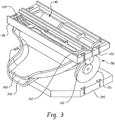
- an embodiment of dispenser 100 includes a dispensing mechanism 150 having a drive member 155 in operable communication with a plurality of N driven members 160, 162 by way of an idler 165, each driven member 160, 162 being associated with a respective one of the compartments 120, 122.
- Each driven member 160, 162 includes a dispensing arm 170 formed on a cam surface 175 of associated cams 180, 182 that facilitates the dispensing of a utensil 125 from the associated compartment 120, 122.
- Cams 180, 182 of associated driven members 160, 162 are coupled by a respective shaft 185, 186. As illustrated, there are two cams 180, 182 for each driven member 160, 162, however, the number of cams can be any number suitable for the purposes disclosed herein.
- the dispensing arms 170 associated with each of the plurality of cams 182 on driven member 162 may be staggered one relative to the other in order to accommodate the profile of the associated utensil 125 and to maintain utensil alignment during dispensing.
- the cam surface 175 of each cam 180, 182 has a spiral-like profile with a step (also depicted by reference numeral 170) that defines the associated dispensing arm 170.
- the dispensing arms 170 associated with each driven member 160, 162 engage with a next-to-be-dispensed utensil 126 (depicted in Figure 5 and also depicted generally by the utensil 125 illustrated in Figure 3 ) located proximate the associated dispensing opening 145.
- a next-to-be-dispensed utensil 126 (depicted in Figure 5 and also depicted generally by the utensil 125 illustrated in Figure 3 ) located proximate the associated dispensing opening 145.
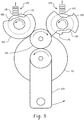
- Figure 5 which depicts a cutaway side view of drive member 155, driven members 160, 162, idler 165, and cams 180, 182
- the spiral-like profile of cam surface 175 is configured to retain the next-in-line utensil 127, while dispensing the next-to-be-dispensed utensil 126, to prevent out-of-sequence dispensing of the utensils.
- drive member 155, driven members 160, 162 and idler 165 are configured as gears (while not specifically illustrated, gear teeth would be disposed on the outer periphery of the various gear members 155, 160, 162, 165, and would mesh with each other according to standard practices), such that driven members 160, 162 are gear-driven by actuation of drive member 155.
- actuation of the drive member 155 in the counterclockwise (CCW) direction causes simultaneous actuation of each driven member 160, 162 in the CCW direction through idler 165 rotating in the clockwise (CW) direction, which causes a next-to-be-dispensed utensil 126 and then a next-in-line utensil 127 to be dispensed from each of the plurality of utensil compartments 120, 122 in repeatable succession one at a time.
- the gear ratios of drive member 155, driven members 160, 162 and idler 165 are such that one rotation of drive member 155 results in a half rotation of driven members 160, 162 and cams 180, 182.
- the dispensing arms 170 associated with driven member 160 need to be 180-degrees out of phase with the dispensing arms 170 associated with driven member 162, as illustrated in Figures 4 and 5 .
- one revolution of the drive member 155 will result in a half revolution of each driven member 160, 162, causing dispensing arms 170 to increment one-half revolution for each one revolution of drive member 155, thereby resulting in alternating dispensing of utensils from the two stacks 125 for uniform depletion of utensil compartments 120, 122.
- a more general relation, however, between the fractional revolution of driven members 160, 162 and drive member 155 may be represented by the ratio (1/N) x , where N is the number of utensil compartments 120, 122 (also the number of driven members 160, 162) and x is a positive integer greater than zero.
- an embodiment of dispenser 100 has the plurality of N utensil compartments 120, 122 so dimensioned and configured to house the same type of utensil, and are disposed one adjacent another such that the utensils 125 within each stack of utensils (generally referred to by reference numerals 126 and 126 in Figure 5 ) are oriented longitudinally parallel with each other. That is, the utensils 125 are lengthwise aligned with the longitudinal axes of top and bottom frames 130, 135.
- each of the plurality of utensil compartments 120, 122 provide access to the interior of each of the compartments, thereby facilitating loading of each compartment with a stack of utensils, which typically have some form of bonding strip that needs to be removed once loaded.
- one CCW rotation of drive member 155 causes one-half CCW rotation of driven members 160, 162 and one-half CCW rotation of associated cams 180, 182, which in turn causes utensil 126 to be pushed off of cam 182 on the first full rotation of drive member 155, and utensil 127 to be pushed off of the cam 180 on the second full rotation of drive member 155.
- a dislodged utensil 125 falls into a respective one of a plurality of dispensing trays 200, 202, with each tray being associated with a respective one of the compartments 120, 122.
- Each tray 200, 202 has a receiving end 205 disposed to receive a dispensed utensil 125 from only the associated compartment (compartment 120 dispensing into tray 200, and compartment 122 dispensing into tray 202), and a dispensing end 210 ( Figure 6 ).
- each tray 200, 202 has an angled dispensing surface 215 having angle ⁇ such that a dispensed utensil slides under the influence of gravity from the receiving end 205 to the dispensing end 210.
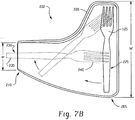
- each tray has a width "W" that is wider than the width " ⁇ " of the respective dispensing end 210, with side walls 220 that engage a dispensed utensil 125 to cause the dispensed utensil to rotate from a first orientation 225 to a second orientation 230 as the dispensed utensil slides under the influence of gravity down dispensing surface 215 (see transition stages of utensil 125 shown in phantom in Figure 7B ).
- the second orientation 230 of utensil 125 presents the holding portion 235 of the utensil to an end user, as opposed to presenting the utility portion 240 of the utensil.
- the degree of rotation of dispensed utensil 125 from the first orientation 225 to the second orientation 230 is 90-degrees.
- each dispensing tray in the plurality N of dispensing trays may have a slightly different profile in order to accommodate the position of the associated receiving end 205 relative to the associated dispensing opening 145 ( Figure 3 ) of the associated utensil compartment 120, 122.
- each dispensing tray will include a side wall 220 that facilitates rotation of the dispensed utensil 125 is it moves under the influence of gravity down dispensing surface 215 ( Figure 6 ). All such tray profiles are considered within the scope of the invention disclosed herein.
- each tray may further include a second dispensing surface 245 proximate the dispensing end 210, the second dispensing surface 245 having a flatter surface, represented by angle y, than the angled dispensing surface 215, represented by angle ⁇ , such that a dispensed utensil decelerates to a stop as it slides under the influence of gravity from the angled dispensing surface 215 to the flatter surface 245.
- each tray may further include a ridge 250 (exaggerated in size for illustration purposes) proximate the dispensing end 210 such that a dispensed utensil stops sliding under the influence of gravity in response to impinging the ridge 250.
- an embodiment of dispenser 100 includes a manually actuatable lever 255 fixedly coupled to the drive member 155, wherein repeated rotation of the lever 255 causes repeated rotation of the drive member 155, which in turn causes a utensil 125 to be dispensed from each of the plurality of compartments 120, 122 in succession one at a time.
- an embodiment of the dispenser 100 may include more than two utensil compartments and two driven members, such as the three utensil compartments 120, 122, 123 and three driven members 160, 162, 163 depicted in Figure 10 .
- two idlers 165, 167 are employed.
- An embodiment also includes a motor 260 in place of the manually actuatable lever 255. The motor 260 is in operable communication with the drive member 155 via a spindle gear 265.
- a dispenser 100 employing a manually actuatable lever 255 may have the gear structure of the drive member, driven members and idler configured such that one revolution of the lever 255 causes one increment of revolution (1/N revolution) of the driven members, which is a convenient and natural mode of manual operation for an end user.
- a dispenser 100 employing a motor 260 may have the gear structure of the drive member, driven members and idler configured such that any defined degree of rotation of the motor causes one increment of revolution (1/N revolution) of the driven members, where the defined degree of rotation of the motor 260 is a matter of design choice.
- a power supply 270 such as a battery pack or a power converter for a wall outlet for example, provides power to the motor 260
- a microprocessor-based controller 275 provides logic to turn on and off the motor 260 on command
- a sensor 281 (best seen by referring to Figure 1 ), such as a proximity sensor or infrared sensor for example, is in signal communication with and provides logical signals to the controller 275 when the presence of a user's hand is detected indicating a request for the dispensing of a utensil 125, for example.
- Other logical signals provided to the controller 275 may be based on the absence of a utensil being available for a user, or removal of the same by a user from a dispensing tray, which will be described in more detail below.
- an embodiment of the dispenser 100 employs a plurality of dispensing trays 200, 202 ( Figures 3 and 4 ) equal in number to the plurality of utensil compartments 120, 122, with one tray being associated with one compartment.
- Such an arrangement permits side wall 220 ( Figures 7A and 7B ) of each tray to be strategically placed relative to the drop point of a utensil in the associated tray such that the distance from the drop point to the side wall 220 is equidistant in each tray, thereby resulting in a sliding utensil, experiencing a constant acceleration under the influence of gravity, to have a defined impact velocity at the respective side wall 220, which will be substantially the same for each tray, and provide for predicable sliding action.
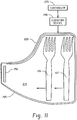
- a deceleration feature such as a flatter second dispensing surface 245 ( Figure 8 ) or a ridge 250 as discussed above, for example, will enable a single dispensing tray to be employed, as depicted in Figure 11 , where a single tray 285 is in dispensing communication with all of the plurality of dispensing compartments (120 and 122 for example), as illustrated by utensils 126 and 127 associated with compartments 122 and 120, respectively (see Figures 2 and 5 for similar reference numerals).
- a first operation of dispensing mechanism 150 would cause the next-to-be-dispensed utensil 126 to drop into tray 285, and a second operation of dispensing mechanism 150 ( Figure 3 ) would cause the next-in-line utensil 127 to drop into tray 285, with each utensil respectively sliding down the angled dispensing surface 215, impinging side wall 220, and rotating in the manner discussed above to present the holding portion of the utensil to an end user.
- a vibratory action may be imparted to any of the aforementioned trays, 200, 202 and 285, by way of any suitable vibratory device 290, such as an electromagnetic or piezoelectric vibrator/buzzer/shaker for example.
- the vibratory device 290 is controlled by controller 275 so that the respective tray vibrates in a timed manner in response to a dispense command.
- dispensing arm 170 has a specific shape depending on whether dispensing compartments 120, 122 are configured to dispense a knife, fork or spoon.
- an embodiment includes cam 182' (interchangeable with cam 182) having a dispensing arm 170' shaped with an undercut for dispensing a spoon or a knife.
- cam 182" (interchangeable with cam 182) having a dispensing arm 170" shaped with a step oppositely angled to an undercut for dispensing a fork. It will be appreciated that cams 182' and 182" are also interchangeable with cam 180 when rotated 180-degrees so that the respective dispensing arms 170' and 170" are oriented as shown in Figure 5 .
- utensil 125 may be configured with a stacking lug 295 disposed at the end of holding portion 235 to assist in more uniform stacking of irregular shaped cutlery designs. That is, stacking lug 295 forms a thicker section at the end of holding portion 235 to separate the holding portions associated with adjacently stacked utensils, one utensil stacked on top of another. While Figures 14 and 15 depict a spoon as an exemplary utensil 125 having a stacking lug 295, such a stacking lug can also be present on a knife, fork or spork.
- an embodiment of the invention may also be configured with a single dispensing tray 300.
- the single dispensing tray 300 is disposed to receive a dispensed utensil 125 from each one of the plurality of N utensil compartments 120, 122 (see Figure 2 ), and, similar to the trays 200, 202 discussed above, includes a receiving end 305 disposed to receive a dispensed utensil and a dispensing end 310 disposed to present the dispensed utensil to a user.
- the dispensing tray 300 includes a first region 315 disposed to cooperate with a holding portion 235 of the dispensed utensil, and a second region 320 disposed to cooperate with a utility portion 240 of the dispensed utensil.
- the first region 315 has a first dispensing surface 325
- the second region 320 has a second dispensing surface 330
- the first dispensing surface 320 being disposed so as to urge the holding portion 235 of the dispensed utensil 125 to slide under the influence of gravity toward the dispensing end 310, while the second dispensing surface 330 retards such sliding action, that is, the second dispensing surface 330 does not promote the same degree of sliding action as does the first dispensing surface 325, thereby causing the dispensed utensil 125 to rotate from a first orientation to a second orientation as the dispensed utensil slides under the influence of gravity, the second orientation being such that holding portion is presented to the user (see Figure 7B for an illustration of the first and second orientations of a dispensed utensil).
- the first dispensing surface 325 comprises a slope that promotes sliding of the holding portion 235 of the dispensed utensil 125 from the receiving end 305 toward the dispensing end 310
- the second dispensing surface 330 comprises a slope that retards such sliding of the utility portion 240 of the dispensed utensil 125 from the receiving end 305 toward the dispensing end 310.
- an embodiment includes an arrangement where the slope of the second dispensing surface 330 is opposite in direction (downward slope being inward versus outward) to the slope of the first dispensing surface 325.
- the scope of the invention is not so limited and also encompasses an arrangement where the slope of the second dispensing surface 330 is substantially flat, that is, the slope of the second dispensing surface 330 is near or close to zero degrees.
- first and second regions 315, 320 are configured with sliding surfaces that promote differing degrees of slippage, as long as the differing degrees of slippage cause the dispensed utensil 125 to rotate during dispensing to present the holding portion 235 of the dispensed utensil to the end user.
- the second region 320 also includes a partial wall 335 disposed at the dispensing end 310 of the second region 320 to capture the utility portion 240 of the dispensed utensil 125 as the holding portion 235 of the dispensed utensil 125 slides under the influence of gravity toward the dispensing end 310.
- An opening 340 at the second region 320 is disposed between the partial wall 335 and the first region 315, which is so dimensioned as to permit the user to withdraw the dispensed utensil 125 from the dispenser 100 through the opening 340 by interfacing with the holding portion 235 of the dispensed utensil 125.
- the combination of sloped ramps 325, 330 will reliably turn a dispensed cutlery utensil 125 independent of variations in frictional forces at the sliding surfaces.
- the center of gravity 345 of a given utensil 125 relative to the left edge 350 of the first dispensing surface 325 is such that the center of gravity 345 is disposed over the second dispensing surface 330 and not over the first dispensing surface 325. That is, as a dispensed utensil 125 drops under the influence of gravity toward the single dispensing tray 300, the center of gravity 345 of the dispensed utensil is positioned over and falls in line with and towards the second dispensing surface 330.
- a dispenser 100 employed for dispensing one type of utensil may have first and second dispensing surfaces 325, 330 with different widths than another dispenser 100 employed for dispensing a different type of utensil. All such dispensers employing first and second dispensing surfaces 325, 330 of different widths are considered within the scope of the invention disclosed herein.
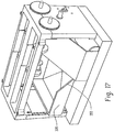
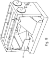
- the partial wall 335 may be configured with sloped surface 355 ( Figure 17 ) or 360 ( Figure 18 ) to form a V-type notch for the holding portion 235 of a dispensed utensil 125 to fall into.
- Such accurate positioning enables dispenser 100 to be equipped with an automated dispensing mechanism that uses a sensor to determine when a utensil has been dispensed.
- V-type notch means any shaped notch that urges the holding portion 235 of a dispensed utensil 125 toward a defined position (that is, any shaped notch suitable for the purposes disclosed herein), which would include without limitation a flattened V-shaped notch, a U-shaped notch, a flattened U-shaped notch, or a narrow square-shaped notch, for example.
- the V-type notch may have a symmetrical or asymmetrical geometry.
- an alternative embodiment of the invention includes a controller 275 having a processing circuit (generally depicted by reference numeral 275) responsive to computer executable instructions which when executed on the processing circuit facilitate dispensing of a utensil 125 from a respective one of the utensil compartments 120, 122 by operation of the motor 260 on command.
- a processing circuit generally depicted by reference numeral 275
- the controller 275 is responsive to computer executable instructions (method 400) when in a powered up state (method block 405). Following a check by a sensor 370 (best seen by referring to Figure 16 ) for the availability of a utensil at opening 340(method block 410), the controller facilitates dispensing of a single piece of cutlery 125 from a respective one of the utensil compartments 120, 122 (method block 415) to the dispensing tray 300.
- sensor 370 may be an optical sensor, a capacitive sensor, an infrared sensor, or a mechanical switch, for example, disposed and configured to sense a utensil at the dispensing end 310 of the dispensing tray 300 and to generate a dispense command (via signal path 375 depicted in Figure 16 ) to the controller 275 to dispense the next-to-be-dispensed utensil 126 upon removal of a utensil 125 from the dispensing tray 300 (method block 420).
- an embodiment of the invention employs the sensor 370 to sense the presence of a utensil 125 at the dispensing tray 300 (method block 420), and in the absence of such a utensil 125 at the dispensing tray 300 generates a dispense command to the controller 275 to dispense a next-to-be-dispensed utensil 126 (method blocks 425 and 415).
- an embodiment of the invention works to always have available a utensil 125 to a user without the user having to actively request such a utensil 125. That is, the next-available utensil is ready and waiting for the user to take.
- controller 275 is responsive to executable instructions to iteratively repeat (method block 425) the sensing of a utensil at the dispensing tray (method block 420) and the dispensing of a next-to-be-dispensed utensil (method block 415) upon removal of a utensil from the dispensing tray 300.
- the "repeat loop" (now referred to by method blocks 425, 427 and 428) is performed up to X-times, and if X is greater than or equal to a defined maximum value (Max), such as but not limited to a value of two for example, then the dispensing mechanism 150 is disabled from dispensing or attempting to dispense a utensil until re-enabled (method block 428).
- a defined maximum value such as but not limited to a value of two for example
- Re-enabling the dispensing mechanism 150 for subsequent dispensing of a utensil is achieved in an embodiment by opening and closing the housing cover 110 (method block 428), which is discussed below in connection with Figure 22 . If a utensil 125 is present at the utensil tray 300 (decision point at method blocks 410 and 420), then controller 275 responds in kind, via recognition of such a condition by sensor 370, to enter into a "hold loop" pattern (method block 430) until the available utensil 125 is removed from the dispensing tray 300.
- Logic flow from the hold loop passes back to method block 420 for subsequent action, and in doing so may pass through an optional timed cycle process (dashed method block 435) where the checking for the availability of a utensil occurs ten-times per second, for example.
- Alternative timed cycles may be utilized in accordance with embodiments and purposes disclosed herein.
- the senor 370 is disposed to sense a utensil 125 at the opening 330 disposed between the partial wall 335 and the first region 315, and in a further embodiment is disposed to sense a utensil resting at a bottom of the V-type notch formed by sloped surface 355 or 360.
- the sensor 370 may be placed at any practical location to sense the presence or absence of a utensil 125.
- the senor 370 is an optical sensor disposed to direct a sensor signal 380 in a direction substantially more toward a utensil 125 at the dispensing tray 300 (directed upwards for example) than toward a user requesting a utensil from the dispenser (directed forwards for example), as illustrated in Figure 16 .
- the sensor 370 is a mechanical switch, such as a microswitch for example, disposed so as to cause a change of state of the switch in response removal of a utensil 125 from the dispensing tray 300.
- the microswitch is disposed proximate the bottom of opening 340 (or bottom of V-type notch formed by sloped surface 355 or 360) such that its actuation lever is actuated by the presence (and subsequent removal thereof) of a utensil 125 resting thereat.
- the senor 281 (depicted in Figure 1 ) is disposed and configured to sense a request from a user for a utensil (method block 505) and to send a command to the controller for dispensing of a utensil in response to such a request (method block 510), the processing circuit of the controller 275 being responsive to the command to facilitate dispensing of a utensil from the utensil compartment.
- an embodiment of the invention awaits a command from a user for a piece of cutlery, and responds in kind.
- the sensor 281 is any of the foregoing sensors discussed above, and more particularly is a capacitive sensor or an infrared sensor, both of which are well known in the art.
- an embodiment includes a check (method block 610) via sensor 370 for the availability of a utensil at the dispensing tray 300 prior to dispensing another utensil when a demand signal from sensor 281 is received at controller 275, thereby avoiding a constant false positive reading if a user continues to request a utensil but does not take the one that is present and available at the dispensing tray 300.
- sensor 281 senses a demand for a utensil (method block 605)
- sensor 370 senses the availability of a utensil ready-and-waiting for a user (method block 610)
- the controller 275 facilitates dispensing of a utensil (method block 615) if a utensil is not ready-and-waiting, otherwise controller 275 enters into a hold loop (method block 620) similar to that previously discussed.
- the disable function discussed above in connection with method block 427 in Figure 19 may also be achieved by the controller 275 switching off power to the motor 260 until a reset command is recognized by the controller 275.
- the disable function and the reset command are achieved by a switch 385 (best seen by referring to Figure 10 ) that is toggled on/off or off/on (depending on whether a normally open or a normally closed switch is used) by removal and replacement of housing cover 110 with respect to base 280, the switch 385 being disposed in an embodiment for direct interaction with the housing cover 110.
- the switch 385 is toggled to a change-of-state condition, which causes a signal to be send via signal path 390 to the controller 275.
- the controller 275 in turn, and in response to computer executable instructions, disables power to the motor 260, which in turn disables actuation of the dispensing mechanism (method block 710), thereby preventing repeated attempts to dispense a utensil when the cover is removed.
- switch 385 When the housing cover 110 is replaced ("close door" designation in method block 715), the switch 385 is again toggled to a change-of-state condition to cause a reset command to be registered by the controller 275, which places the controller 275 in a powered up state (method block 720), ready for implementation of the method 400 depicted in Figure 19 . While switch 385 is depicted disposed in a certain location on base 280, it will be appreciated that this is for illustration purposes only, and that switch 385 may be disposed in any location in dispenser 100 suitable for the purposes disclosed herein.
- switch 385 is disposed in a location accessible by maintenance personnel such that a reset command can be registered by the controller 275 and the dispensing mechanism 150 re-enabled without the need to remove/replace the housing cover 110.
- switch 385 or the controller 275 is responsive to a wireless signal, such as a radio frequency (RF) or infrared (IR) signal for example, that causes a reset command to be registered with the controller 275, thereby allowing maintenance personnel to negate an erroneous disable condition or to reset the system.
- RF radio frequency
- IR infrared
- some embodiments of the invention may include some of the following advantages: a cutlery utensil dispenser capable of dispensing cutlery utensils from a plurality of utensil compartments; and, a cutlery utensil dispenser capable of uniformly depleting a plurality of utensil compartments from which the utensils are dispensed. Additionally, some embodiments provide an effective means of hygienically metering cutlery. For example, cutlery that is available via an open container can be contaminated by food, condiments, human contact, and the like, which leads to the cutlery being thrown-away. Embodiments disclosed herein can offer a significant cost savings to the establishment dispensing the cutlery, which can ultimately be shared with the end-user of the cutlery (e.g., a customer in a food service establishment).
Landscapes
- Containers And Packaging Bodies Having A Special Means To Remove Contents (AREA)
- Table Devices Or Equipment (AREA)
- Washing And Drying Of Tableware (AREA)
Description
- The present disclosure relates generally to a cutlery utensil dispenser, and particularly to a multi-stack cutlery utensil dispenser.
- Eating facilities often provide cutlery utensils in dispensing bins, where all customers place their hands into the bins in order to retrieve a knife, fork, spoon or spork. While such arrangements provide for economical dispensing of cutlery utensils, as opposed to sets of utensils being separately wrapped in plastic sleeves, the open air bins are not very hygienic, and can spread hand-carried bacteria and the like to other utensils in the bin or potentially to another customer.
- In an attempt to address concerns relating to the dispensing of hygienic cutlery utensils, enclosed dispensers have been employed where a stack of cutlery utensils are placed in a utensil compartment and dispensed one at a time on command by operation of a dispensing lever. Such arrangements may be suitable for their intended purpose, but are also limited by the capacity of utensils they are capable of holding. One remedy to such a deficiency may be to simply make the utensil compartment taller, thereby enabling multiple stacks of pre-measured and preassembled cutlery utensils to be placed one on top of the other. However, such a dispenser would be quite tall, would require refilling from a relatively high level, and would require each of the separate stacks to be properly aligned one on top of the other during refilling so that the cutlery utensils are properly aligned for dispensing. In view of these and other deficiencies, there is a need in the art for an improved cutlery utensil dispenser.
- Document
US 2007/0193968 A1 discloses a cutlery utensil dispenser comprising a utensil compartment, dimensioned and configured to house a stack of utensils having a dispensing opening through which a dispensed utensil passes, a dispensing mechanism comprising a drive member in operable communication with a driven member being associated with the compartment having a dispensing arm that facilitates the dispensing of a utensil from the compartment, wherein actuation of the drive member causes a utensil to be dispensed from the compartment in repeatable succession one at a time. - An embodiment of the invention includes a cutlery utensil dispenser having a plurality of N utensil compartments and a dispensing mechanism. Each of the utensil compartments are so dimensioned and configured to house a stack of utensils, each compartment having a dispensing opening through which a dispensed utensil passes. The dispensing mechanism includes a drive member in operable communication with a plurality of N driven members, each driven member being associated with a respective one of the compartments, each driven member having a dispensing arm that facilitates the dispensing of a utensil from the associated compartment. Actuation of the drive member causes simultaneous actuation of each driven member that causes a utensil to be dispensed from each of the plurality of compartments in repeatable succession one at a time.
- Referring to the exemplary drawings wherein like elements are numbered alike in the accompanying Figures:
-
Figure 1 depicts in isometric view a cutlery utensil dispenser having a dispensing mechanism in accordance with an embodiment of the invention; -
Figure 2 depicts in isometric view the dispenser ofFigure 1 with cover removed to show internal components of the dispenser; -
Figure 3 depicts in isometric view portions of the internal components ofFigure 2 in greater detail; -
Figure 4 depicts in isometric view portions of the internal components ofFigure 3 in greater detail; -
Figure 5 depicts in side view portions of the dispensing mechanism in accordance with an embodiment of the invention; -
Figure 6 depicts in cross section side view a dispensing tray in accordance with an embodiment of the invention; -
Figures 7A and7B depict plan views of dispensing trays in accordance with an embodiment of the invention, withFigure 7B depicting a dispensed cutlery utensil in various stages of dispensing; -
Figures 8 and 9 depict in cross section side view alternative dispensing trays to that ofFigure 6 ; -
Figure 10 depicts in isometric view an alternative dispensing mechanism to that ofFigures 2-5 and in accordance with an embodiment of the invention; -
Figure 11 depicts in plan view a single dispensing tray in accordance with an alternative embodiment; -
Figures 12 and 13 depict in side view dispensing arms of the dispensing mechanism in accordance with alternative embodiments; -
Figures 14 and 15 depict in isometric view a cutlery utensil and portion thereof, respectively, for use in accordance with an embodiment of the invention; -
Figure 16 depicts in isometric view an alternative dispensing tray in accordance with an embodiment of the invention; -
Figures 17 and18 depict in isometric view alternative dispensing trays to that ofFigure 16 ; and -
Figures 19-22 depict flowcharts of alternative methods. - An embodiment of the invention, as shown and described by the various figures and accompanying text, provides a cutlery utensil dispenser configured for dispensing utensils one at a time in succession from a plurality of utensil compartments each housing a stack of utensils, and a dispensing method applicable thereto. While the embodiments described herein depict a fork as an example utensil, it will be appreciated that the disclosed invention is also applicable to other cutlery utensils, such as knives, spoons and sporks, for example. The stack of utensils may be made from any type of material, such as plastic, metal, wood, or plastic-coated compressed paper, for example.
-
Figures 1 and2 depict an embodiment of acutlery utensil dispenser 100 with and without, respectively,side walls 105, ahousing cover 110, and atray cover 115. Referring more specifically toFigure 2 , thedispenser 100 includes a plurality ofN utensil compartments utensils 125 in each. As depicted inFigure 2 , the value of "N" is "2". However, as will be appreciated by the discussion herein, the value of "N" may be any integer suitable for the intended purpose disclosed herein, such as 2, 3, 4 or 5 for example. While only one utensil 125 (fork illustrated) is depicted inFigure 2 , it will be appreciated that a stack ofutensils 125 would result by placing and/or nesting one on top of another, with one stack being placed within each rectangular shapedcompartment - In an embodiment, each
compartment top frame 130, abottom frame 135, and side supports 140 for retaining the stack ofutensils 125. Thebottom frame 135 has a dispensing opening 145 (best seen by referring toFigure 3 ) through which a dispensedutensil 125 passes. - Reference is now made to
Figures 3 and4 , whereFigure 3 depicts the elements ofFigure 2 withcompartments Figure 4 depicts the elements ofFigure 3 with eachbottom frame 135 andutensil 125 removed. As depicted, an embodiment of dispenser 100 (Figure 1 ) includes adispensing mechanism 150 having adrive member 155 in operable communication with a plurality of N drivenmembers idler 165, each drivenmember compartments member arm 170 formed on acam surface 175 of associatedcams utensil 125 from the associatedcompartment Cams members respective shaft cams member arms 170 associated with each of the plurality ofcams 182 on driven member 162 (and similarly for dispensingarms 170 associated with each of the plurality ofcams 180 on driven member 160) may be staggered one relative to the other in order to accommodate the profile of theassociated utensil 125 and to maintain utensil alignment during dispensing. Thecam surface 175 of eachcam dispensing arm 170. The dispensingarms 170 associated with each drivenmember Figure 5 and also depicted generally by theutensil 125 illustrated inFigure 3 ) located proximate the associateddispensing opening 145. Referring now toFigure 5 , which depicts a cutaway side view ofdrive member 155, drivenmembers idler 165, andcams cam surface 175 is configured to retain the next-in-line utensil 127, while dispensing the next-to-be-dispensed utensil 126, to prevent out-of-sequence dispensing of the utensils. - In an embodiment,
drive member 155, drivenmembers idler 165 are configured as gears (while not specifically illustrated, gear teeth would be disposed on the outer periphery of thevarious gear members members drive member 155. As such, actuation of thedrive member 155 in the counterclockwise (CCW) direction, with respect to the view ofFigure 5 , causes simultaneous actuation of each drivenmember idler 165 rotating in the clockwise (CW) direction, which causes a next-to-be-dispensedutensil 126 and then a next-in-line utensil 127 to be dispensed from each of the plurality ofutensil compartments drive member 155, drivenmembers idler 165, are such that one rotation ofdrive member 155 results in a half rotation of drivenmembers cams dispenser 100 having twoutensil compartments arms 170 associated with drivenmember 160 need to be 180-degrees out of phase with the dispensingarms 170 associated with drivenmember 162, as illustrated inFigures 4 and5 . - As discussed above and illustrated in
Figures 4 and5 , one revolution of thedrive member 155 will result in a half revolution of each drivenmember arms 170 to increment one-half revolution for each one revolution ofdrive member 155, thereby resulting in alternating dispensing of utensils from the twostacks 125 for uniform depletion ofutensil compartments members drive member 155 may be represented by the ratio (1/N)x, where N is the number ofutensil compartments 120, 122 (also the number of drivenmembers 160, 162) and x is a positive integer greater than zero. For a configuration where N=2 and x=2 (in comparison,Figure 5 depicts a configuration where N=2 and x=1), one revolution ofdrive member 155 would result in ¼ revolution of each drivenmember arms 170 spaced 180-degrees apart, percam arms 170 oncam 182 being 90-degrees out of phase with the set of dispensingarms 170 oncam 180. More generally, the dispensingarms 170 of each driven member are displaced (1/N)x intervals of revolution with respect to each other. As can be seen from the foregoing discussion, a variety of gear ratios and numbers of dispensing arms per cam may be employed without departing from the scope of the disclosed invention, all of which are contemplated herein. - With reference back to
Figure 2 , an embodiment ofdispenser 100 has the plurality ofN utensil compartments utensils 125 within each stack of utensils (generally referred to byreference numerals Figure 5 ) are oriented longitudinally parallel with each other. That is, theutensils 125 are lengthwise aligned with the longitudinal axes of top andbottom frames Side openings 190 in each of the plurality ofutensil compartments - As discussed above and with reference now to
Figures 3-5 , one CCW rotation ofdrive member 155 causes one-half CCW rotation of drivenmembers cams utensil 126 to be pushed off ofcam 182 on the first full rotation ofdrive member 155, andutensil 127 to be pushed off of thecam 180 on the second full rotation ofdrive member 155. Under the influence of gravity, a dislodgedutensil 125 falls into a respective one of a plurality of dispensingtrays compartments tray end 205 disposed to receive a dispensedutensil 125 from only the associated compartment (compartment 120 dispensing intotray 200, andcompartment 122 dispensing into tray 202), and a dispensing end 210 (Figure 6 ). - Referring now to
Figure 6 , which depicts a section cut side view of tray 200 (also applicable totray 202 for discussion purposes) in an orientation representative of an in-use dispenser (see orientation with respect to base 280), eachtray surface 215 having angle θ such that a dispensed utensil slides under the influence of gravity from the receivingend 205 to the dispensingend 210. - As illustrated in
Figures 7A and7B , which depict plan views oftrays end 205 of each tray has a width "W" that is wider than the width "ω" of therespective dispensing end 210, withside walls 220 that engage a dispensedutensil 125 to cause the dispensed utensil to rotate from afirst orientation 225 to asecond orientation 230 as the dispensed utensil slides under the influence of gravity down dispensing surface 215 (see transition stages ofutensil 125 shown in phantom inFigure 7B ). As illustrated inFigure 7B , thesecond orientation 230 ofutensil 125 presents the holdingportion 235 of the utensil to an end user, as opposed to presenting theutility portion 240 of the utensil. In an embodiment, the degree of rotation of dispensedutensil 125 from thefirst orientation 225 to thesecond orientation 230 is 90-degrees. - As indicated by the illustrations of
trays Figures 7A and7B , each dispensing tray in the plurality N of dispensing trays may have a slightly different profile in order to accommodate the position of the associated receivingend 205 relative to the associated dispensing opening 145 (Figure 3 ) of the associatedutensil compartment side wall 220 that facilitates rotation of the dispensedutensil 125 is it moves under the influence of gravity down dispensing surface 215 (Figure 6 ). All such tray profiles are considered within the scope of the invention disclosed herein. - In an alternative embodiment, and with reference now to
Figure 8 , which depicts a section cut side view of an alternative tray 200' of tray 200 (also applicable to an alternative of tray 202), each tray may further include asecond dispensing surface 245 proximate the dispensingend 210, thesecond dispensing surface 245 having a flatter surface, represented by angle y, than the angled dispensingsurface 215, represented by angle θ, such that a dispensed utensil decelerates to a stop as it slides under the influence of gravity from the angled dispensingsurface 215 to theflatter surface 245. - In a further alternative embodiment, and with reference now to
Figure 9 , which depicts a section cut side view of analternative tray 200" of tray 200 (also applicable to an alternative of tray 202), each tray may further include a ridge 250 (exaggerated in size for illustration purposes) proximate the dispensingend 210 such that a dispensed utensil stops sliding under the influence of gravity in response to impinging theridge 250. - Referring back to
Figures 1 ,2 and5 , an embodiment ofdispenser 100 includes a manuallyactuatable lever 255 fixedly coupled to thedrive member 155, wherein repeated rotation of thelever 255 causes repeated rotation of thedrive member 155, which in turn causes autensil 125 to be dispensed from each of the plurality ofcompartments - With reference to
Figure 10 (and with periodic reference toFigures 1 and2 ), and as discussed above, an embodiment of thedispenser 100 may include more than two utensil compartments and two driven members, such as the threeutensil compartments members Figure 10 . To drive the three drivenmembers idlers motor 260 in place of the manuallyactuatable lever 255. Themotor 260 is in operable communication with thedrive member 155 via aspindle gear 265. As with the actuation of thelever 255, repeated actuation of themotor 260 causes autensil 125 to be dispensed from each of the plurality ofcompartments motor 260 causing one increment of rotation of the drivenmembers Figure 10 , one increment of rotation of the driven members is 1/N or 1/3 rotation. - As an aside, a
dispenser 100 employing a manuallyactuatable lever 255 may have the gear structure of the drive member, driven members and idler configured such that one revolution of thelever 255 causes one increment of revolution (1/N revolution) of the driven members, which is a convenient and natural mode of manual operation for an end user. On the other hand, adispenser 100 employing amotor 260 may have the gear structure of the drive member, driven members and idler configured such that any defined degree of rotation of the motor causes one increment of revolution (1/N revolution) of the driven members, where the defined degree of rotation of themotor 260 is a matter of design choice. - With reference still to
Figure 10 , apower supply 270, such as a battery pack or a power converter for a wall outlet for example, provides power to themotor 260, a microprocessor-basedcontroller 275 provides logic to turn on and off themotor 260 on command, and a sensor 281 (best seen by referring toFigure 1 ), such as a proximity sensor or infrared sensor for example, is in signal communication with and provides logical signals to thecontroller 275 when the presence of a user's hand is detected indicating a request for the dispensing of autensil 125, for example. Other logical signals provided to thecontroller 275 may be based on the absence of a utensil being available for a user, or removal of the same by a user from a dispensing tray, which will be described in more detail below. - While certain combinations and quantities of drive member, driven members and idlers have been described herein, it will be appreciated that these certain combinations are for illustration purposes only and that any combination of any of the foregoing drive member, driven members and idlers may be employed in accordance with an embodiment of the invention as disclosed herein. Any and all such combinations are contemplated herein and are considered within the scope of the invention disclosed.
- While an embodiment of the invention has been described employing a gear-driven dispenser, it will be appreciated that the scope of the invention is not so limited, and that the invention also applies to a dispenser having any other type of drive system suitable for the purposes disclosed herein, such as a belt-drive system or a chain-drive system for example.
- As discussed above, an embodiment of the
dispenser 100 employs a plurality of dispensingtrays 200, 202 (Figures 3 and4 ) equal in number to the plurality ofutensil compartments Figures 7A and7B ) of each tray to be strategically placed relative to the drop point of a utensil in the associated tray such that the distance from the drop point to theside wall 220 is equidistant in each tray, thereby resulting in a sliding utensil, experiencing a constant acceleration under the influence of gravity, to have a defined impact velocity at therespective side wall 220, which will be substantially the same for each tray, and provide for predicable sliding action. However, it is also contemplated that utilization of a deceleration feature, such as a flatter second dispensing surface 245 (Figure 8 ) or aridge 250 as discussed above, for example, will enable a single dispensing tray to be employed, as depicted inFigure 11 , where asingle tray 285 is in dispensing communication with all of the plurality of dispensing compartments (120 and 122 for example), as illustrated byutensils compartments Figures 2 and5 for similar reference numerals). Here, a first operation of dispensingmechanism 150 would cause the next-to-be-dispensed utensil 126 to drop intotray 285, and a second operation of dispensing mechanism 150 (Figure 3 ) would cause the next-in-line utensil 127 to drop intotray 285, with each utensil respectively sliding down the angled dispensingsurface 215, impingingside wall 220, and rotating in the manner discussed above to present the holding portion of the utensil to an end user. - In an embodiment, and to assist in a uniform sliding motion of each dispensed
utensil 125, a vibratory action may be imparted to any of the aforementioned trays, 200, 202 and 285, by way of any suitablevibratory device 290, such as an electromagnetic or piezoelectric vibrator/buzzer/shaker for example. In an embodiment, thevibratory device 290 is controlled bycontroller 275 so that the respective tray vibrates in a timed manner in response to a dispense command. - In an embodiment, and with reference to
Figures 12 and 13 , dispensingarm 170 has a specific shape depending on whether dispensingcompartments Figure 12 , an embodiment includes cam 182' (interchangeable with cam 182) having a dispensing arm 170' shaped with an undercut for dispensing a spoon or a knife. And with reference toFigure 13 , an embodiment includescam 182" (interchangeable with cam 182) having a dispensingarm 170" shaped with a step oppositely angled to an undercut for dispensing a fork. It will be appreciated thatcams 182' and 182" are also interchangeable withcam 180 when rotated 180-degrees so that the respective dispensingarms 170' and 170" are oriented as shown inFigure 5 . - In an embodiment, and with reference to
Figures 14 and 15 ,utensil 125 may be configured with a stackinglug 295 disposed at the end of holdingportion 235 to assist in more uniform stacking of irregular shaped cutlery designs. That is, stackinglug 295 forms a thicker section at the end of holdingportion 235 to separate the holding portions associated with adjacently stacked utensils, one utensil stacked on top of another. WhileFigures 14 and 15 depict a spoon as anexemplary utensil 125 having a stackinglug 295, such a stacking lug can also be present on a knife, fork or spork. - Alternative to the plurality of
N dispensing trays 200, 202 (Figure 2 ) discussed above, and with reference now toFigure 16 , an embodiment of the invention may also be configured with asingle dispensing tray 300. Here, thesingle dispensing tray 300 is disposed to receive a dispensedutensil 125 from each one of the plurality of N utensil compartments 120, 122 (seeFigure 2 ), and, similar to thetrays end 305 disposed to receive a dispensed utensil and a dispensingend 310 disposed to present the dispensed utensil to a user. The dispensingtray 300 includes afirst region 315 disposed to cooperate with a holdingportion 235 of the dispensed utensil, and asecond region 320 disposed to cooperate with autility portion 240 of the dispensed utensil. Thefirst region 315 has afirst dispensing surface 325, and thesecond region 320 has asecond dispensing surface 330, thefirst dispensing surface 320 being disposed so as to urge the holdingportion 235 of the dispensedutensil 125 to slide under the influence of gravity toward the dispensingend 310, while thesecond dispensing surface 330 retards such sliding action, that is, thesecond dispensing surface 330 does not promote the same degree of sliding action as does thefirst dispensing surface 325, thereby causing the dispensedutensil 125 to rotate from a first orientation to a second orientation as the dispensed utensil slides under the influence of gravity, the second orientation being such that holding portion is presented to the user (seeFigure 7B for an illustration of the first and second orientations of a dispensed utensil). - In an embodiment, the
first dispensing surface 325 comprises a slope that promotes sliding of the holdingportion 235 of the dispensedutensil 125 from the receivingend 305 toward the dispensingend 310, and thesecond dispensing surface 330 comprises a slope that retards such sliding of theutility portion 240 of the dispensedutensil 125 from the receivingend 305 toward the dispensingend 310. As illustrated inFigure 16 , an embodiment includes an arrangement where the slope of thesecond dispensing surface 330 is opposite in direction (downward slope being inward versus outward) to the slope of thefirst dispensing surface 325. However, it will be appreciated that the scope of the invention is not so limited and also encompasses an arrangement where the slope of thesecond dispensing surface 330 is substantially flat, that is, the slope of thesecond dispensing surface 330 is near or close to zero degrees. - From the foregoing, it will be appreciated that the first and
second regions utensil 125 to rotate during dispensing to present the holdingportion 235 of the dispensed utensil to the end user. - In an embodiment, the
second region 320 also includes apartial wall 335 disposed at the dispensingend 310 of thesecond region 320 to capture theutility portion 240 of the dispensedutensil 125 as the holdingportion 235 of the dispensedutensil 125 slides under the influence of gravity toward the dispensingend 310. Anopening 340 at thesecond region 320 is disposed between thepartial wall 335 and thefirst region 315, which is so dimensioned as to permit the user to withdraw the dispensedutensil 125 from thedispenser 100 through theopening 340 by interfacing with the holdingportion 235 of the dispensedutensil 125. - By employing the
single tray 300 as described above, the combination of slopedramps cutlery utensil 125 independent of variations in frictional forces at the sliding surfaces. - To further assist in reliably turning a dispensed
cutlery utensil 125, the center ofgravity 345 of a givenutensil 125 relative to theleft edge 350 of thefirst dispensing surface 325 is such that the center ofgravity 345 is disposed over thesecond dispensing surface 330 and not over thefirst dispensing surface 325. That is, as a dispensedutensil 125 drops under the influence of gravity toward thesingle dispensing tray 300, the center ofgravity 345 of the dispensed utensil is positioned over and falls in line with and towards thesecond dispensing surface 330. Since knives, forks, spoons and sporks naturally may have centers of gravity at different locations along their respective lengths, adispenser 100 employed for dispensing one type of utensil may have first and second dispensing surfaces 325, 330 with different widths than anotherdispenser 100 employed for dispensing a different type of utensil. All such dispensers employing first and second dispensing surfaces 325, 330 of different widths are considered within the scope of the invention disclosed herein. - To further assist in accurately positioning the holding
portion 235 of a dispensedutensil 125 at the dispensingend 310 oftray 300, and with reference now toFigures 16-18 collectively, thepartial wall 335 may be configured with sloped surface 355 (Figure 17 ) or 360 (Figure 18 ) to form a V-type notch for the holdingportion 235 of a dispensedutensil 125 to fall into. Such accurate positioning enablesdispenser 100 to be equipped with an automated dispensing mechanism that uses a sensor to determine when a utensil has been dispensed. As used herein, the term "V-type notch" means any shaped notch that urges the holdingportion 235 of a dispensedutensil 125 toward a defined position (that is, any shaped notch suitable for the purposes disclosed herein), which would include without limitation a flattened V-shaped notch, a U-shaped notch, a flattened U-shaped notch, or a narrow square-shaped notch, for example. The V-type notch may have a symmetrical or asymmetrical geometry. - While an embodiment of the invention has been described employing a manually actuatable lever that rotates about an axis in one revolution increments to operate a gear-driven system of the dispenser, it will be appreciated that the scope of the invention is not so limited, and that the invention also applies to a dispenser having any other operable lever arrangement suitable for the purposes disclosed herein, such as a cantilevered lever that is depressed through a defined amount of displacement, operates a drive system through a pawl-and-ratchet interface, and is spring loaded to return to a detent position ready for another dispensing action.
- In addition to the forgoing, an alternative embodiment of the invention includes a
controller 275 having a processing circuit (generally depicted by reference numeral 275) responsive to computer executable instructions which when executed on the processing circuit facilitate dispensing of autensil 125 from a respective one of the utensil compartments 120, 122 by operation of themotor 260 on command. - With reference now to
Figure 19 , thecontroller 275 is responsive to computer executable instructions (method 400) when in a powered up state (method block 405). Following a check by a sensor 370 (best seen by referring toFigure 16 ) for the availability of a utensil at opening 340(method block 410), the controller facilitates dispensing of a single piece ofcutlery 125 from a respective one of the utensil compartments 120, 122 (method block 415) to the dispensingtray 300. To facilitate automatic dispensing of a next-to-be-dispensed utensil 126 (method block 415),sensor 370 may be an optical sensor, a capacitive sensor, an infrared sensor, or a mechanical switch, for example, disposed and configured to sense a utensil at the dispensingend 310 of the dispensingtray 300 and to generate a dispense command (viasignal path 375 depicted inFigure 16 ) to thecontroller 275 to dispense the next-to-be-dispensed utensil 126 upon removal of autensil 125 from the dispensing tray 300 (method block 420). That is, an embodiment of the invention employs thesensor 370 to sense the presence of autensil 125 at the dispensing tray 300 (method block 420), and in the absence of such autensil 125 at the dispensingtray 300 generates a dispense command to thecontroller 275 to dispense a next-to-be-dispensed utensil 126 (method blocks 425 and 415). Here, an embodiment of the invention works to always have available autensil 125 to a user without the user having to actively request such autensil 125. That is, the next-available utensil is ready and waiting for the user to take. As such, thecontroller 275 is responsive to executable instructions to iteratively repeat (method block 425) the sensing of a utensil at the dispensing tray (method block 420) and the dispensing of a next-to-be-dispensed utensil (method block 415) upon removal of a utensil from the dispensingtray 300. In an alternative embodiment, and with reference to method blocks 427 and 428 depicted in dashed line form inFigure 19 to illustrate an alternative embodiment, the "repeat loop" (now referred to by method blocks 425, 427 and 428) is performed up to X-times, and if X is greater than or equal to a defined maximum value (Max), such as but not limited to a value of two for example, then thedispensing mechanism 150 is disabled from dispensing or attempting to dispense a utensil until re-enabled (method block 428). Such disabling is advantageous to prevent repeated attempts to dispense a utensil when the utensil compartments 120, 122 are empty. Re-enabling thedispensing mechanism 150 for subsequent dispensing of a utensil is achieved in an embodiment by opening and closing the housing cover 110 (method block 428), which is discussed below in connection withFigure 22 . If autensil 125 is present at the utensil tray 300 (decision point at method blocks 410 and 420), thencontroller 275 responds in kind, via recognition of such a condition bysensor 370, to enter into a "hold loop" pattern (method block 430) until theavailable utensil 125 is removed from the dispensingtray 300. Logic flow from the hold loop (method block 430) passes back to method block 420 for subsequent action, and in doing so may pass through an optional timed cycle process (dashed method block 435) where the checking for the availability of a utensil occurs ten-times per second, for example. Alternative timed cycles may be utilized in accordance with embodiments and purposes disclosed herein. - In an embodiment, the
sensor 370 is disposed to sense autensil 125 at theopening 330 disposed between thepartial wall 335 and thefirst region 315, and in a further embodiment is disposed to sense a utensil resting at a bottom of the V-type notch formed by slopedsurface sensor 370 may be placed at any practical location to sense the presence or absence of autensil 125. - In an embodiment, the
sensor 370 is an optical sensor disposed to direct asensor signal 380 in a direction substantially more toward autensil 125 at the dispensing tray 300 (directed upwards for example) than toward a user requesting a utensil from the dispenser (directed forwards for example), as illustrated inFigure 16 . In an alternative embodiment, thesensor 370 is a mechanical switch, such as a microswitch for example, disposed so as to cause a change of state of the switch in response removal of autensil 125 from the dispensingtray 300. That is, the microswitch is disposed proximate the bottom of opening 340 (or bottom of V-type notch formed by slopedsurface 355 or 360) such that its actuation lever is actuated by the presence (and subsequent removal thereof) of autensil 125 resting thereat. - In an alternative embodiment, and with reference now to the
method 500 depicted inFigure 20 , the sensor 281 (depicted inFigure 1 ) is disposed and configured to sense a request from a user for a utensil (method block 505) and to send a command to the controller for dispensing of a utensil in response to such a request (method block 510), the processing circuit of thecontroller 275 being responsive to the command to facilitate dispensing of a utensil from the utensil compartment. Here, an embodiment of the invention awaits a command from a user for a piece of cutlery, and responds in kind. In an embodiment, thesensor 281 is any of the foregoing sensors discussed above, and more particularly is a capacitive sensor or an infrared sensor, both of which are well known in the art. - In an alternative embodiment to that of
Figure 20 , and with reference now to themethod 600 ofFigure 21 , an embodiment includes a check (method block 610) viasensor 370 for the availability of a utensil at the dispensingtray 300 prior to dispensing another utensil when a demand signal fromsensor 281 is received atcontroller 275, thereby avoiding a constant false positive reading if a user continues to request a utensil but does not take the one that is present and available at the dispensingtray 300. Following the logic path ofmethod 600,sensor 281 senses a demand for a utensil (method block 605),sensor 370 senses the availability of a utensil ready-and-waiting for a user (method block 610), and thecontroller 275 facilitates dispensing of a utensil (method block 615) if a utensil is not ready-and-waiting, otherwisecontroller 275 enters into a hold loop (method block 620) similar to that previously discussed. - In an embodiment, the disable function discussed above in connection with
method block 427 inFigure 19 may also be achieved by thecontroller 275 switching off power to themotor 260 until a reset command is recognized by thecontroller 275. In an embodiment, the disable function and the reset command are achieved by a switch 385 (best seen by referring toFigure 10 ) that is toggled on/off or off/on (depending on whether a normally open or a normally closed switch is used) by removal and replacement ofhousing cover 110 with respect tobase 280, theswitch 385 being disposed in an embodiment for direct interaction with thehousing cover 110. That is, and with reference now tomethod 700 ofFigure 22 , when thehousing cover 110 is removed ("open door" designation in method block 705), such as for reloading empty utensil compartments 120, 122 for example, theswitch 385 is toggled to a change-of-state condition, which causes a signal to be send viasignal path 390 to thecontroller 275. Thecontroller 275 in turn, and in response to computer executable instructions, disables power to themotor 260, which in turn disables actuation of the dispensing mechanism (method block 710), thereby preventing repeated attempts to dispense a utensil when the cover is removed. When thehousing cover 110 is replaced ("close door" designation in method block 715), theswitch 385 is again toggled to a change-of-state condition to cause a reset command to be registered by thecontroller 275, which places thecontroller 275 in a powered up state (method block 720), ready for implementation of themethod 400 depicted inFigure 19 . Whileswitch 385 is depicted disposed in a certain location onbase 280, it will be appreciated that this is for illustration purposes only, and thatswitch 385 may be disposed in any location indispenser 100 suitable for the purposes disclosed herein. For example, an embodiment is contemplated whereswitch 385 is disposed in a location accessible by maintenance personnel such that a reset command can be registered by thecontroller 275 and thedispensing mechanism 150 re-enabled without the need to remove/replace thehousing cover 110. Another embodiment is contemplated where theswitch 385 or thecontroller 275 is responsive to a wireless signal, such as a radio frequency (RF) or infrared (IR) signal for example, that causes a reset command to be registered with thecontroller 275, thereby allowing maintenance personnel to negate an erroneous disable condition or to reset the system. - As disclosed, some embodiments of the invention may include some of the following advantages: a cutlery utensil dispenser capable of dispensing cutlery utensils from a plurality of utensil compartments; and, a cutlery utensil dispenser capable of uniformly depleting a plurality of utensil compartments from which the utensils are dispensed. Additionally, some embodiments provide an effective means of hygienically metering cutlery. For example, cutlery that is available via an open container can be contaminated by food, condiments, human contact, and the like, which leads to the cutlery being thrown-away. Embodiments disclosed herein can offer a significant cost savings to the establishment dispensing the cutlery, which can ultimately be shared with the end-user of the cutlery (e.g., a customer in a food service establishment).
- While the invention has been described with reference to exemplary embodiments, it will be understood by those skilled in the art that various changes may be made and equivalents may be substituted for elements thereof without departing from the scope of the invention, as defined by the appended claims.
Claims (15)
- A cutlery utensil dispenser (100) for dispensing cutlery utensils, comprising:a plurality of N utensil compartments (120, 122), each compartment being so dimensioned and configured to house a stack of utensils (125), each compartment having a dispensing opening (145) through which a dispensed utensil passes;a dispensing mechanism (150) comprising a drive member (155) in operable communication with a plurality of N driven members (160, 162), each driven member being associated with a respective one of the compartments (120, 122), each driven member having a dispensing arm (170) that facilitates the dispensing of a utensil from the associated compartment;wherein actuation of the drive member (155) causes simultaneous actuation of each driven member (160, 162) that causes a utensil to be dispensed from each of the plurality of compartments (120, 122) in repeatable succession one at a time.
- The dispenser of Claim 1, wherein the plurality of N driven members (160, 162) are gear-driven by the drive member (155).
- The dispenser of Claim 2, wherein one revolution of the drive member (155) cause (1/N)x revolutions of each driven member (160, 162), where x is a positive integer greater than zero.
- The dispenser of Claim 3, wherein the dispensing arms (170) of each driven member (160,162) are circumferentially displaced (1/N)x intervals of revolution with respect to each other.
- The dispenser of Claim 1, wherein each driven member (160, 162) comprises:a cam surface (175) having a spiral-like profile with a step that defines the associated dispensing arm (170); the dispensing arm (170) of each driven member (160, 162) being engageable with a next-to-be-dispensed utensil located proximate the associated dispensing opening (145); the spiral-like profile being configured to retain the next-in-line utensil to prevent out-of-sequence dispensing thereof.
- The dispenser of Claim 1, further comprising:a plurality of dispensing trays (200, 202), each tray being associated with a respective one of the compartments (120, 122), each tray having a receiving end (205) disposed to receive a dispensed utensil from only the associated compartment, and a dispensing end (210); each tray having an angled dispensing surface (215) such that a dispensed utensil slides under the influence of gravity from the receiving end to the dispensing end, the receiving end being wider than the dispensing end with side walls (220) that engage a dispensed utensil to cause the dispensed utensil to rotate from a first orientation (225) to a second orientation (230) as the dispensed utensil slides under the influence of gravity.
- The dispenser of Claim 6, wherein each of the utensils (125) have a holding portion (235) and a utility portion (240), and the second orientation (230) is such that holding portion is presented to an end user.
- The dispenser of Claim 1, further comprising a manually actuatable lever (255) in operable communication with the drive member (155), wherein repeated actuation of the lever causes a utensil to be dispensed from each of the plurality of compartments in succession one at a time.
- The dispenser of Claim 1, further comprising a motor (260) in operable communication with the drive member (155), wherein repeated actuation of the motor causes a utensil to be dispensed from each of the plurality of compartments in succession one at a time.
- The dispenser of Claim 9, further comprising:a sensor (281) in operable communication with a controller (275); wherein the controller is in operable communication with the motor (260) to cause actuation of the drive member (155) upon receipt of a signal from the sensor.
- The dispenser of Claim 1, further comprising:a dispensing tray (300) disposed to receive a dispensed utensil from each one of the plurality of N utensil compartments;the dispensing tray having a receiving end (305) disposed to receive a dispensed utensil and a dispensing end (310) disposed to present the dispensed utensil to a user;the dispensing tray having a first region (315) disposed to cooperate with a holding portion of the dispensed utensil, and a second region (320) disposed to cooperate with a utility portion of the dispensed utensil;the first region having a first dispensing surface (325), and the second region having a second dispensing surface (330), the first dispensing surface disposed so as to urge the holding portion of the dispensed utensil to slide under the influence of gravity toward the dispensing end (310) while the second dispensing surface retards such sliding action, thereby causing the dispensed utensil to rotate from a first orientation to a second orientation as the dispensed utensil slides under the influence of gravity, the second orientation being such that holding portion (235) is presented to the user.
- The dispenser of Claim 11, wherein:the second region (320) comprises a partial wall (335) disposed at the dispensing end of the second region to capture the utility portion (210) of the dispensed utensil as the holding portion of the dispensed utensil slides under the influence of gravity toward the dispensing end.
- The dispenser of Claim 11, wherein:the first dispensing surface (325) and the second dispensing surface (330) are disposed such that a center of gravity of the dispensed utensil is positioned over the second dispensing surface such that the center of gravity falls in line with and towards the second dispensing surface under the influence of gravity.
- The dispenser of Claim 10, wherein:the controller (275) dispenses a single piece of cutlery from the utensil compartment in response to a piece of cutlery not being available for a user at a dispensing tray (300) of the dispenser.
- The dispenser of Claim 14, further comprising:a dispensing tray (300) disposed to receive a dispensed utensil; anda sensor (370) disposed and configured to sense a utensil at the dispensing tray and to generate the command to the controller (275) to dispense a next-to-be-dispensed utensil upon removal of a utensil from the dispensing tray.
Applications Claiming Priority (2)
| Application Number | Priority Date | Filing Date | Title |
|---|---|---|---|
| US12/247,805 US8360273B2 (en) | 2008-10-08 | 2008-10-08 | Cutlery utensil dispenser |
| PCT/US2009/059915 WO2010042673A1 (en) | 2008-10-08 | 2009-10-08 | Cutlery utensil dispenser |
Publications (2)
| Publication Number | Publication Date |
|---|---|
| EP2365769A1 EP2365769A1 (en) | 2011-09-21 |
| EP2365769B1 true EP2365769B1 (en) | 2017-11-22 |
Family
ID=41509781
Family Applications (1)
| Application Number | Title | Priority Date | Filing Date |
|---|---|---|---|
| EP09741089.8A Not-in-force EP2365769B1 (en) | 2008-10-08 | 2009-10-08 | Cutlery utensil dispenser |
Country Status (6)
| Country | Link |
|---|---|
| US (1) | US8360273B2 (en) |
| EP (1) | EP2365769B1 (en) |
| CN (1) | CN102170812B (en) |
| CA (1) | CA2738487C (en) |
| MX (1) | MX2011003099A (en) |
| WO (1) | WO2010042673A1 (en) |
Cited By (1)
| Publication number | Priority date | Publication date | Assignee | Title |
|---|---|---|---|---|
| WO2022249058A1 (en) * | 2021-05-25 | 2022-12-01 | Philippe Caraveo | Device for dispensing cutlery items |
Families Citing this family (53)
| Publication number | Priority date | Publication date | Assignee | Title |
|---|---|---|---|---|
| US8152004B2 (en) | 2005-05-05 | 2012-04-10 | Dixie Consumer Products Llc | Dispenser for disposable cutlery and components therefor |
| US8210364B2 (en) | 2005-05-05 | 2012-07-03 | Dixie Consumer Products Llc | Dispenser for disposable cutlery and components therefor |
| MX2009004907A (en) * | 2006-11-07 | 2009-08-27 | Dixie Consumer Products Llc | Cutlery dispenser and method of dispensing cutlery. |
| US9237815B2 (en) * | 2006-11-07 | 2016-01-19 | Dixie Consumer Products Llc | Cutlery dispenser and method of dispensing cutlery |
| US20130192070A1 (en) * | 2007-02-28 | 2013-08-01 | Yuval Amit | Strainer device and method for manufacturing the strainer |
| US8701932B2 (en) | 2008-10-08 | 2014-04-22 | Dixie Consumer Products Llc | Cutlery dispenser trays |
| US8070013B2 (en) * | 2009-01-06 | 2011-12-06 | Dixie Consumer Products Llc | Cutlery utensil dispensing apparatus and method |
| US9295344B2 (en) * | 2010-03-19 | 2016-03-29 | Dixie Consumer Products Llc | Cutlery utensil dispenser |
| CN102858206B (en) * | 2010-04-26 | 2016-09-07 | 皇家飞利浦电子股份有限公司 | Agitator or spoon dispenser for beverage dispenser |
| CA2801727C (en) | 2010-06-08 | 2019-05-14 | Gpcp Ip Holdings Llc | System and method for holding cutlery together |
| CA2805660C (en) | 2010-08-12 | 2018-09-18 | Gpcp Ip Holdings Llc | Interlocking cutlery and related methods |
| MX2013001725A (en) | 2010-08-24 | 2013-10-28 | Dixie Consumer Products Llc | Removable strip for packaging cutlery and related methods. |
| US8464905B2 (en) | 2010-10-29 | 2013-06-18 | S.C. Johnson & Son, Inc. | Dispensers and functional operation and timing control improvements for dispensers |
| MX342721B (en) * | 2010-12-10 | 2016-10-11 | Dixie Consumer Products Llc | Dispensing mechanism for utensil dispenser and related methods. |
| CA2820552C (en) | 2010-12-10 | 2019-01-08 | Gpcp Ip Holdings Llc | Screw drive for dispensing cutlery and related methods |
| MX353821B (en) * | 2010-12-14 | 2018-01-31 | Gpcp Ip Holdings Llc | Belt drive for dispensing cutlery and related methods. |
| US20120251988A1 (en) * | 2011-04-01 | 2012-10-04 | Joshua Thomas Moffatt | Reward dispenser |
| US9439518B2 (en) | 2011-08-19 | 2016-09-13 | Dixie Consumer Products Llc | Cutlery dispenser |
| US9044522B2 (en) | 2011-09-19 | 2015-06-02 | S.C. Johnson & Son, Inc. | Spray dispenser |
| USD668088S1 (en) | 2012-01-26 | 2012-10-02 | Parker Barbara A | Plastic flatware dispenser |
| US9049948B2 (en) | 2012-01-27 | 2015-06-09 | Us Foods, Inc. | Utensil dispenser |
| ITTO20120761A1 (en) * | 2012-09-03 | 2014-03-04 | N&W Global Vending Spa | MIXING MACHINE DISPENSER DEVICE IN AN AUTOMATIC BEVERAGE DISTRIBUTOR |
| US9266646B2 (en) | 2012-09-07 | 2016-02-23 | Dixie Consumer Products Llc | Cutlery utensil dispensing package |
| US9108782B2 (en) | 2012-10-15 | 2015-08-18 | S.C. Johnson & Son, Inc. | Dispensing systems with improved sensing capabilities |
| CN103251254B (en) * | 2013-04-21 | 2017-07-07 | 朱贤华 | The quantitative sending trap of service plate |
| WO2015013204A1 (en) | 2013-07-25 | 2015-01-29 | Dixie Consumer Products Llc | Cutlery dispenser and related methods |
| MX368586B (en) | 2013-07-25 | 2019-10-08 | Gpcp Ip Holdings Llc | Cutlery dispenser and related methods. |
| CN105636879A (en) | 2013-08-08 | 2016-06-01 | 迪克西消费产品有限公司 | Front loading cutlery dispenser |
| US9332861B2 (en) | 2013-08-19 | 2016-05-10 | Dixie Consumer Products Llc | Cutlery dispenser and methods of use |
| CA2944590C (en) | 2014-04-11 | 2021-04-13 | Dixie Consumer Products Llc | Forward advancing cutlery dispenser |
| CN103919422B (en) * | 2014-04-21 | 2015-07-08 | 宁波家联塑料科技有限公司 | Table fork dispenser |
| US9931174B2 (en) * | 2014-06-27 | 2018-04-03 | Camilo Machado | Glove dispenser |
| US9700153B2 (en) * | 2014-09-30 | 2017-07-11 | Gadsden Coffee Company, Inc. | Automated hygienic cutlery dispenser |
| EP3689190B1 (en) * | 2016-06-13 | 2025-01-01 | GPCP IP Holdings LLC | Cutlery dispenser |
| WO2018006062A1 (en) * | 2016-06-30 | 2018-01-04 | Jade Group International Llc | Cutlery dispenser |
| US10470859B2 (en) * | 2016-10-13 | 2019-11-12 | Paula Evette Nesbitt | Sterile dental setup pack |
| US10932591B2 (en) | 2017-05-22 | 2021-03-02 | Robert F. Hubbard | Utensil dispenser system |
| US10413089B2 (en) * | 2017-12-21 | 2019-09-17 | Recycline, Inc. | Cutlery dispenser |
| USD852006S1 (en) | 2018-01-24 | 2019-06-25 | Gpcp Ip Holdings Llc | Knife |
| US10881220B2 (en) * | 2018-01-24 | 2021-01-05 | Gpcp Ip Holdings Llc | Utensil dispensers with interlock mechanism |
| USD852007S1 (en) | 2018-01-24 | 2019-06-25 | Gpcp Ip Holdings Llc | Fork |
| US10779661B2 (en) * | 2018-01-24 | 2020-09-22 | Gpcp Ip Holdings Llc | Utensil dispensers with glide mechanism for loading |
| USD851466S1 (en) | 2018-01-24 | 2019-06-18 | Gpcp Ip Holdings Llc | Spoon |
| US10631665B2 (en) | 2018-01-24 | 2020-04-28 | Gpcp Ip Holdings Llc | Cutlery dispensing assemblies and methods |
| US11147393B2 (en) * | 2018-01-24 | 2021-10-19 | Gpcp Ip Holdings Llc | Utensil dispenser with rail system |
| US10881221B2 (en) * | 2018-01-24 | 2021-01-05 | Gpcp Ip Holdings Llc | Utensil dispensers with stack gauge |
| US10842293B2 (en) * | 2018-01-24 | 2020-11-24 | Gpcp Ip Holdings Llc | Utensil dispensers having improved prime mechanism |
| AU2019342602A1 (en) | 2018-09-21 | 2021-04-15 | Gpcp Ip Holdings Llc | Dispenser for disposable utensils |
| US20220177251A1 (en) * | 2019-03-26 | 2022-06-09 | Jaryd Ridgeway | An automatic dispenser |
| USD920052S1 (en) * | 2019-08-30 | 2021-05-25 | Kolor Magnetic (Shenzhen) Co., Ltd. | Utensil dispenser |
| CN112617589A (en) * | 2020-12-22 | 2021-04-09 | 周国栋 | Automatic selling machine for steamed products |
| CN112586960B (en) * | 2020-12-30 | 2024-11-08 | 歌乐电磁(深圳)有限公司 | A rotating dislocation feeding structure and tableware taking device thereof |
| CA3217691A1 (en) * | 2023-10-25 | 2025-06-16 | 1360625 B.C. Ltd. | Medical cartridge dispensers, and related methods of use |
Family Cites Families (166)
| Publication number | Priority date | Publication date | Assignee | Title |
|---|---|---|---|---|
| US592105A (en) | 1897-10-19 | Amos barnes | ||
| US925485A (en) | 1908-08-28 | 1909-06-22 | Francis E Lafler | Match-box. |
| US999837A (en) | 1910-06-17 | 1911-08-08 | Standard Vending Company | Coin-controlled vending-machine. |
| US1259927A (en) | 1912-12-02 | 1918-03-19 | Us Envelope Co | Vending-calinet for collapsible drinking-cups or the like. |
| US1146447A (en) * | 1914-05-08 | 1915-07-13 | Harold W C Prommel | Sanitary toothpick-dispenser. |
| US1355583A (en) | 1919-10-11 | 1920-10-12 | Solace Comfort Service Corp | Vending-machine |
| US1482071A (en) * | 1922-03-06 | 1924-01-29 | Lee F Duff | Dispensing stand |
| US1504098A (en) | 1922-11-27 | 1924-08-05 | Hardy L Cathey | Pencil-dispensing machine |
| US1547151A (en) | 1923-06-15 | 1925-07-21 | John F Watling | Coin-controlled vending machine |
| US1546077A (en) | 1923-12-14 | 1925-07-14 | Cooperative Vending Machine Co | Vending machine |
| US1675510A (en) * | 1924-04-08 | 1928-07-03 | John R Nolan | Vending machine |
| FR613105A (en) * | 1925-11-07 | 1926-11-09 | Dispensing device for cigarettes and other objects | |
| US1577302A (en) * | 1926-01-02 | 1926-03-16 | William N Jenkins | Vending machine |
| GB327172A (en) * | 1928-12-27 | 1930-03-27 | Dearsley George | Improvements in or relating to packing machinery |
| US2078984A (en) | 1932-01-21 | 1937-05-04 | Ice Cream Dispensing Corp | Package dispensing apparatus |
| US2053828A (en) | 1934-11-09 | 1936-09-08 | Harper Percy Stephen | Coin-freed machine |
| US2110189A (en) * | 1936-04-16 | 1938-03-08 | William A Zeidler | Device for dispensing table implements |
| US2149098A (en) * | 1936-07-06 | 1939-02-28 | Sani Self Server Corp | Dispensing apparatus for knives and like articles |
| US2149099A (en) | 1937-04-07 | 1939-02-28 | Sani Self Server Corp | Dispensing apparatus |
| US2141684A (en) | 1938-04-05 | 1938-12-27 | Joseph A Diemer | Dispensing device |
| US2188573A (en) | 1938-04-09 | 1940-01-30 | Longo Salvatore | Dispensing |
| US2207528A (en) | 1939-06-28 | 1940-07-09 | Carl A Witt | Sanitary toothpick dispenser |
| US2421782A (en) | 1939-12-28 | 1947-06-10 | William J Gibbs | Dispenser for tableware |
| US2268873A (en) | 1940-02-10 | 1942-01-06 | Oval Wood Dish Corp | Article dispensing device |
| US2260596A (en) * | 1940-05-16 | 1941-10-28 | L A Young Spring & Wire Corp | Spring assembly and upholstery supporting mat therefor |
| US2268596A (en) | 1940-05-18 | 1942-01-06 | Jerum Henry | Dispensing apparatus |
| US2239196A (en) | 1940-07-01 | 1941-04-22 | Lunvik Rasmus | Vending and display device |
| US2340561A (en) * | 1941-08-27 | 1944-02-01 | Renfro Randolph Howard | Spoon dispenser |
| US2472051A (en) * | 1946-11-15 | 1949-05-31 | Gillette Safety Razor Co | Blade-dispensing container |
| US2571668A (en) | 1947-07-12 | 1951-10-16 | Interborough News Company | Coin-controlled vending machine |
| US2646874A (en) * | 1947-08-08 | 1953-07-28 | Gillette Co | Blade dispensing magazine |
| US2635025A (en) * | 1949-10-28 | 1953-04-14 | Badger Vending Machines Co | Dispensing device |
| US2671555A (en) * | 1949-12-15 | 1954-03-09 | Gillette Co | Blade dispenser with used blade compartment |
| US2577344A (en) * | 1950-01-10 | 1951-12-04 | Ramona D Masure | Narcotic dispenser |
| US2692691A (en) * | 1950-04-15 | 1954-10-26 | Harriss | Nested article dispenser |
| US2752678A (en) | 1954-12-24 | 1956-07-03 | Arthur R Welch | Molded spoon construction |
| US2868344A (en) | 1955-01-10 | 1959-01-13 | Wendell H Shields | Vending machine |
| US2965262A (en) | 1955-09-06 | 1960-12-20 | Rowe Mfg Co Inc | Gravity feed package merchandising machine |
| US2889076A (en) * | 1955-10-03 | 1959-06-02 | Robert J Van Schie | Dispensing container for razor blades |
| US2924357A (en) * | 1955-10-18 | 1960-02-09 | Stapling Machines Co | Slat feeder |
| US2954948A (en) | 1956-04-10 | 1960-10-04 | Francis M Johnson | Chaff dispensing system |
| US2877926A (en) * | 1956-09-26 | 1959-03-17 | Pfizer & Co C | Article dispensing apparatus |
| US2880907A (en) * | 1957-03-06 | 1959-04-07 | Artez F Mainers | Article dispenser |
| US2911127A (en) * | 1957-09-05 | 1959-11-03 | Driss | Machine for dispensing spoons or like articles |
| US2946431A (en) * | 1957-12-02 | 1960-07-26 | Gillette Co | Blade dispenser |
| US3083879A (en) * | 1958-03-24 | 1963-04-02 | Clarence B Coleman | Dispensing bin |
| US3146908A (en) * | 1960-03-29 | 1964-09-01 | Seeburg Corp | Vending machine having a plurality of dispensing compartments |
| US3095114A (en) | 1960-09-14 | 1963-06-25 | Rock Ola Mfg Corp | Packet ejector with optional latch |
| US3100842A (en) * | 1961-06-15 | 1963-08-13 | Gerald Leon Ritter | Tooth brush holder and sterilizer |
| US3114475A (en) * | 1961-07-27 | 1963-12-17 | Newsomatic Corp | Vending machine |
| US3163327A (en) | 1962-07-09 | 1964-12-29 | Fisher & Ludlow Ltd | Coin vending machine |
| US3132765A (en) | 1962-07-20 | 1964-05-12 | Florendo Alex | Silverware dispenser |
| US3263860A (en) | 1964-07-07 | 1966-08-02 | Ct Mint Co | Article dispenser including a reciprocating ejector |
| US3300087A (en) | 1965-05-04 | 1967-01-24 | Difco Lab Inc | Article dispensing magazine and a dispenser with removable magazines |
| GB1088654A (en) | 1965-05-07 | 1967-10-25 | Stephen Arthur Jones | Disposable tongs |
| US3313452A (en) | 1965-10-15 | 1967-04-11 | Katz Jacob | Dispensing device having a pivoted article delivery member |
| US3371821A (en) | 1966-05-25 | 1968-03-05 | Frederick J. Abood Jr. | Dispensing apparatus |
| US3334784A (en) | 1966-06-06 | 1967-08-08 | Baker Perkins Ltd | Rotary article dispenser with predetermined count control |
| US3426941A (en) * | 1966-06-14 | 1969-02-11 | Hoe & Co R | Adjustable vertical feeder means for stacked articles |
| US3472421A (en) | 1967-10-18 | 1969-10-14 | Albert H Baller | Dispenser having an ejector for dispensing articles one by one |
| US3499538A (en) | 1967-12-13 | 1970-03-10 | David S Sherard | Hot dog holder |
| US3558006A (en) | 1968-11-18 | 1971-01-26 | Benjamin Redmond | Butter pat dispenser |
| US3587922A (en) | 1969-11-05 | 1971-06-28 | Biagio Oriti | Automatic cigarette box |
| US3680736A (en) | 1970-08-05 | 1972-08-01 | Hans Viessmann | Rotary valve dispenser for tablets |
| DE7033238U (en) | 1970-09-07 | 1970-11-26 | Theysohn Friedrich Fa | PLASTIC DINING TOOLS. |
| DE7127677U (en) | 1971-07-19 | 1971-11-11 | Wuerttembergische Metallwarenfabrik | Cutlery made of plastic |
| US3786959A (en) * | 1972-04-05 | 1974-01-22 | K Greb | Paper clip dispenser |
| NL7509802A (en) * | 1975-08-18 | 1977-02-22 | Claasen Antonius Bernardus | METHOD OF PACKAGING A DOSING SPOON, INSTALLATION FOR THE PERFORMANCE OF THIS METHOD AND DOSING SPOON SET UP FOR USE IN THIS METHOD AND DEVICE, TOGETHER WITH A HOLDER MACHINE. |
| US4134519A (en) | 1977-10-21 | 1979-01-16 | Burton Barnett | Dispenser for elongate thin flexible articles |
| US4308974A (en) * | 1980-02-29 | 1982-01-05 | Jones Linda M | Tampon dispener |
| DE3151268C2 (en) | 1981-12-24 | 1985-06-13 | Bellaplast Gmbh, 6200 Wiesbaden | Cutlery |
| US4489854A (en) | 1982-07-26 | 1984-12-25 | Traex Corporation | Dispensing unit for elongated articles |
| JPS59123732U (en) | 1983-02-09 | 1984-08-20 | 不二精器株式会社 | Rotating damper with directionality |
| US4524512A (en) | 1983-04-25 | 1985-06-25 | O Tray Corporation | Nestable, stackable cutlery |
| JPS6079032U (en) | 1983-11-07 | 1985-06-01 | 株式会社ニフコ | oil damper |
| US4570536A (en) * | 1984-03-02 | 1986-02-18 | Dodd Robert N | Electrically actuated can crusher |
| US4571773A (en) | 1984-06-08 | 1986-02-25 | Nifco Inc. | Damper for braking rotation |
| JPS6124850A (en) | 1984-07-16 | 1986-02-03 | Nifco Inc | One way damper |
| US4610087A (en) | 1984-12-24 | 1986-09-09 | State Of New Mexico | Eating utensil for correctional institutions |
| JPS61192937A (en) | 1985-02-21 | 1986-08-27 | Nifco Inc | Rotary damper |
| ES286032Y (en) * | 1985-04-15 | 1986-06-01 | Jofemar,S.A. | UNIT AND AUTOMATIC PRODUCT DISPENSER DEVICE |
| US4662536A (en) | 1985-12-06 | 1987-05-05 | Powers Ernest G | Paper filter dispenser |
| US4789064A (en) | 1987-09-24 | 1988-12-06 | Paul Segal | Retainer clip for utensils |
| US4896792A (en) | 1987-09-28 | 1990-01-30 | Michel Marchand | Automatic dispensing device for products and central warehouse or store constructed with such devices |
| AT390593B (en) * | 1988-06-22 | 1990-05-25 | Hinterreiter Ignaz | TABLET DISPENSER |
| US4973037A (en) | 1988-12-28 | 1990-11-27 | Pitney Bowes Inc. | Front end feeder for mail handling machine |
| IT1227855B (en) * | 1989-01-16 | 1991-05-10 | Carnisio Umberto G | IMPROVED EQUIPMENT FOR THE AUTOMATIC DISTRIBUTION OF CONES AND SIMILAR, INTENDED TO CONTAIN ICE CREAM. |
| JP2884267B2 (en) | 1991-03-11 | 1999-04-19 | 株式会社ニフコ | Rotary damper |
| US5131586A (en) | 1991-04-18 | 1992-07-21 | Akiva Buchberg | Pleated packaging wrapper and method of wrapping objects using the same |
| DK0593630T3 (en) | 1991-07-01 | 1998-07-20 | Andre Monfredo | Hot food vending machine which uses one or more microwave ovens |
| US5127546A (en) * | 1991-08-08 | 1992-07-07 | Chen Ming Ho | Storage bin structure for an automatic vending machine |
| FR2681582B1 (en) | 1991-09-24 | 1994-12-23 | Akiva Buchberg | PACKAGING MADE FROM A THIN PLEATED SHEET AND A SEMI-RIGID CONFORMABLE SHEET TO CONTAIN SOLID BULK PRODUCTS. |
| DE4139938A1 (en) | 1991-12-04 | 1993-06-09 | Heinz-Peter 5650 Solingen De Knoop | Cutlery with handle, such as knife, fork, spoon - has straight or triple-curved handle, with finger recesses, and projection acting as stand in transition between handle and blade. |
| US5211267A (en) | 1992-02-24 | 1993-05-18 | Prince Corporation | Temperature compensated rotary damper |
| US5191997A (en) | 1992-06-03 | 1993-03-09 | Mechtronics Corporation | Carousel-type gravity feed film dispenser and film cassette therefor |
| US5249705A (en) * | 1992-08-12 | 1993-10-05 | Paul A. Wiebel | Coupon dispenser |
| USD342648S (en) * | 1992-08-27 | 1993-12-28 | Dart Industries Inc. | Eating utensil |
| US5509522A (en) * | 1992-10-28 | 1996-04-23 | Laidlaw; Ronald W. | Quick release hopper and improved cylindrical dispensing member for individual cigarette vending machine |
| DE4244484C2 (en) | 1992-12-30 | 2003-04-17 | Itw Ateco Gmbh | rotary damper |
| US5413317A (en) | 1993-04-22 | 1995-05-09 | Prince Corporation | Damping device |
| US5469688A (en) * | 1993-07-26 | 1995-11-28 | Michael D. Dunbar | Method for wrapping silverware in a napkin |
| SE509769C2 (en) | 1993-09-03 | 1999-03-08 | Itw Ateco Gmbh | rotational dampers |
| DE9316566U1 (en) | 1993-10-29 | 1994-01-27 | De Ster N.V., Hoogstraten | Containers from parts of a disposable cutlery |
| JP3304188B2 (en) | 1994-02-23 | 2002-07-22 | 株式会社ニフコ | One-way rotary damper |
| US5586685A (en) | 1994-09-27 | 1996-12-24 | Dorner Mfg. Corp. | Apparatus for dispensing articles |
| DE9420646U1 (en) | 1994-12-23 | 1995-02-16 | Itw-Ateco Gmbh, 22844 Norderstedt | Rotary damper |
| FR2731758B1 (en) | 1995-03-16 | 1997-06-13 | Itw De France | ROTATION RETARDER AND USE THEREOF |
| US5542508A (en) | 1995-06-26 | 1996-08-06 | Illinois Tool Works Inc. | Fluid free damper |
| JP3194888B2 (en) * | 1996-10-22 | 2001-08-06 | 株式会社湯山製作所 | Continuous plastic ampule separating device |
| IT1297194B1 (en) | 1997-01-30 | 1999-08-03 | Magistris Giovanni De | DISTRIBUTION DEVICE FOR DISPOSABLE FOOD BUCKETS |
| US5921408A (en) | 1997-11-04 | 1999-07-13 | Fort James Corporation | Cutlery dispenser |
| US6202891B1 (en) | 1998-10-23 | 2001-03-20 | Microbrush, Corporation | Dispenser for liquid applicator |
| US6023913A (en) * | 1998-11-09 | 2000-02-15 | Reginald M. Mudd | Apparatus and method for wrapping silverware within a napkin |
| DE19906369C1 (en) | 1999-01-19 | 2000-02-24 | Hekuma Herbst Maschinenbau Gmb | Fully automatic pressure injection molding of plastic parts, adds one of many possible types of ultimately functionless fastenings solely assisting assembly for packing and transport |
| EP1022107A1 (en) | 1999-01-19 | 2000-07-26 | HEKUMA Herbst Maschinenbau GmbH | Method and apparatus for manufacturing plastic articles |
| US6378729B1 (en) * | 1999-03-04 | 2002-04-30 | Kabushiki Kaisha Yuyama Seisakusho | Ampule storage container for dispensing ampules at a constant rate |
| US6047830A (en) | 1999-05-14 | 2000-04-11 | Chang; Yuan Fu | Retainer for receiving knives and cutting boards |
| IT1307782B1 (en) | 1999-07-16 | 2001-11-19 | Stefano Casebasse | DISPENSER DISPENSER OF PALETTE (OR SPOONS) TO LOSE FROZEN AND OTHER, WITH CONVENTION FOR THE SLIDING EXTRACTION OF THE |
| IT1307781B1 (en) | 1999-07-16 | 2001-11-19 | Stefano Casebasse | A PACKAGE FOR A PLURALITY OF ICE CREAM PALETTE AND MORE, MANIPULABLE TO PROVIDE PALETTE DISPENSERS. |
| US6250498B1 (en) | 1999-10-26 | 2001-06-26 | Scott Lovejoy | Spoon dispenser |
| US6336568B1 (en) * | 2000-03-15 | 2002-01-08 | Terence Tucker | Cutlery utensil dispenser |
| US6298960B1 (en) | 2000-05-30 | 2001-10-09 | Illinois Tool Works Inc. | Small viscous precision damper |
| JP4092452B2 (en) * | 2000-06-05 | 2008-05-28 | 旭精工株式会社 | Box-shaped automatic discharge device |
| DE10196765B4 (en) | 2000-10-26 | 2013-03-28 | Piolax Inc. | rotary damper |
| US20020135102A1 (en) | 2001-02-12 | 2002-09-26 | Forbes Alan H. | Injection-molded, mineral-filled articles and processes for making the same |
| US20020112445A1 (en) * | 2001-02-16 | 2002-08-22 | Benny Scaduto | Device for automatically wrapping eating utensils in a napkin |
| DE20111599U1 (en) * | 2001-07-11 | 2001-09-13 | Leica Microsystems Nussloch GmbH, 69226 Nußloch | Dispenser for thin knives, especially for thin replacement microtome knives |
| US6626633B2 (en) | 2001-12-28 | 2003-09-30 | Awi Licensing Company | Apparatus for feeding a panel from a stack |
| FR2835581B1 (en) | 2002-02-04 | 2005-07-01 | Itw Fastex France | ROTATING RETARDER DEVICE AND USE THEREOF |
| DE10219379A1 (en) | 2002-04-30 | 2003-11-20 | Streetvending Ag | Device for the automatic delivery of a product |
| WO2004015533A2 (en) * | 2002-08-08 | 2004-02-19 | The Vendo Company | Self-learning depth logic for multi-depth vendor control |
| US6972033B2 (en) * | 2002-08-26 | 2005-12-06 | Advanced Medical Optics, Inc. | Accommodating intraocular lens assembly with multi-functional capsular bag ring |
| US6837028B1 (en) | 2002-09-03 | 2005-01-04 | Mario L. Miano | Automated flatware and napkin assembling apparatus |
| US20040045860A1 (en) * | 2002-09-05 | 2004-03-11 | Edgerly Randall L. | Packages of stacked, individually wrapped, flat disposable utensils, and methods of forming such packages |
| JP4181831B2 (en) | 2002-09-09 | 2008-11-19 | 株式会社ニフコ | damper |
| US6786357B2 (en) * | 2002-09-19 | 2004-09-07 | Oxalight L.L.C. | Vending machine for chemiluminescent novelty items |
| AU2003272162A1 (en) | 2002-09-26 | 2004-04-19 | Benedykt Prusecki | Method of disposable cutlery dispensing, stack of cutlery and dispenser therefor |
| US6832694B2 (en) * | 2002-11-07 | 2004-12-21 | Fort James Corporation | Dispenser for cutlery utensils |
| USD492549S1 (en) | 2003-01-07 | 2004-07-06 | Robert Welch Designs Limited | Cutlery set |
| USD493337S1 (en) | 2003-01-07 | 2004-07-27 | Robert Welch Designs Limited | Fork and spoon |
| US7076932B2 (en) | 2003-01-21 | 2006-07-18 | Richard Howard Rubin | Apparatus and method for wrapping |
| US7520247B2 (en) * | 2003-02-04 | 2009-04-21 | Jerry D. Rutledge | Animal food and treat dispenser |
| ITMI20030410U1 (en) | 2003-09-11 | 2005-03-12 | Sud Service S R L | PLASTIC MAIL |
| US20050082307A1 (en) | 2003-10-21 | 2005-04-21 | Terence Tucker | Cutlery dispenser system |
| US20060000190A1 (en) | 2003-11-24 | 2006-01-05 | Behnke Janica S | Apparatus and method for packaging sheet material |
| CN2673224Y (en) | 2004-01-16 | 2005-01-26 | 李清茂 | Dinnerware |
| CA2558358A1 (en) | 2004-01-26 | 2005-08-11 | Convenience Enterprises, Inc. | Food service set assembly system |
| US8152004B2 (en) * | 2005-05-05 | 2012-04-10 | Dixie Consumer Products Llc | Dispenser for disposable cutlery and components therefor |
| US8210364B2 (en) * | 2005-05-05 | 2012-07-03 | Dixie Consumer Products Llc | Dispenser for disposable cutlery and components therefor |
| DE202005013647U1 (en) | 2005-08-29 | 2006-06-08 | FiLiGrande, Fischer & Linne GbR (vertretungsberechtigter Gesellschafter: Herr Hans-Peter Fischer, 38448 Wolfsburg) | cutlery |
| PL206270B1 (en) | 2005-10-28 | 2010-07-30 | Zieliński Antoni Przedsiębiorstwo Produkcyjno Handlowe Zelan Zpchrzieliński Antoni Przedsiębiorstwo Produkcyjno Handlowe Zelan Zpchr | Disposable cutlery |
| US7516831B2 (en) * | 2005-11-14 | 2009-04-14 | Kil Jae Chang | Coin-operated item vending and game apparatus housing with foreign object removal-enabling means |
| US20070131705A1 (en) * | 2005-12-09 | 2007-06-14 | Behravesh Casey B | Object dispenser |
| US7210279B1 (en) * | 2005-12-14 | 2007-05-01 | Ahmed Ibrahim A | Device for wrapping a napkin about silverware and associated method |
| CN2865478Y (en) | 2005-12-24 | 2007-02-07 | 燕山大学 | automatic spoon machine |
| DE102006019532A1 (en) * | 2006-03-08 | 2007-09-20 | Gabler Thermoform Gmbh & Co. Kg | Thermoforming machine |
| CH696456A5 (en) | 2006-05-02 | 2007-06-29 | Fostag Holding Ag | Stackable cutlery. |
| US7322172B2 (en) * | 2006-05-24 | 2008-01-29 | Wrapmaster, Inc. | Utensil wrapping apparatus and method |
| ITRE20060068A1 (en) | 2006-06-05 | 2007-12-06 | Ducale Macchine Da Caffe | ¿AUTOMATIC CUTLERY SERVICE SYSTEM ¿ |
| MX2009004907A (en) | 2006-11-07 | 2009-08-27 | Dixie Consumer Products Llc | Cutlery dispenser and method of dispensing cutlery. |
| US20080128445A1 (en) * | 2006-12-05 | 2008-06-05 | Hsi Ping Huang | Dispenser having advertisement counting effect |
| US8701932B2 (en) * | 2008-10-08 | 2014-04-22 | Dixie Consumer Products Llc | Cutlery dispenser trays |
| USD591104S1 (en) * | 2008-11-13 | 2009-04-28 | Dixie Consumer Products Llc | Cutlery utensil |
| US20100147869A1 (en) * | 2008-12-12 | 2010-06-17 | The Stanley Works | Blade dispenser |
| US9295344B2 (en) * | 2010-03-19 | 2016-03-29 | Dixie Consumer Products Llc | Cutlery utensil dispenser |
| CA2801727C (en) * | 2010-06-08 | 2019-05-14 | Gpcp Ip Holdings Llc | System and method for holding cutlery together |
-
2008
- 2008-10-08 US US12/247,805 patent/US8360273B2/en active Active
-
2009
- 2009-10-08 WO PCT/US2009/059915 patent/WO2010042673A1/en not_active Ceased
- 2009-10-08 MX MX2011003099A patent/MX2011003099A/en active IP Right Grant
- 2009-10-08 CN CN200980138847.3A patent/CN102170812B/en not_active Expired - Fee Related
- 2009-10-08 CA CA2738487A patent/CA2738487C/en active Active
- 2009-10-08 EP EP09741089.8A patent/EP2365769B1/en not_active Not-in-force
Cited By (2)
| Publication number | Priority date | Publication date | Assignee | Title |
|---|---|---|---|---|
| WO2022249058A1 (en) * | 2021-05-25 | 2022-12-01 | Philippe Caraveo | Device for dispensing cutlery items |
| FR3123187A1 (en) * | 2021-05-25 | 2022-12-02 | Philippe CARAVÉO | Cutlery dispensing device |
Also Published As
| Publication number | Publication date |
|---|---|
| MX2011003099A (en) | 2011-05-30 |
| CN102170812A (en) | 2011-08-31 |
| WO2010042673A1 (en) | 2010-04-15 |
| EP2365769A1 (en) | 2011-09-21 |
| CA2738487C (en) | 2017-09-19 |
| US20100084418A1 (en) | 2010-04-08 |
| US8360273B2 (en) | 2013-01-29 |
| CA2738487A1 (en) | 2010-04-15 |
| CN102170812B (en) | 2015-02-04 |
Similar Documents
| Publication | Publication Date | Title |
|---|---|---|
| US8360273B2 (en) | Cutlery utensil dispenser | |
| CN101218610B (en) | Dispensing trays for vending machines | |
| US9237815B2 (en) | Cutlery dispenser and method of dispensing cutlery | |
| US8297473B2 (en) | Cutlery dispenser and method of dispensing cutlery | |
| CA2944590C (en) | Forward advancing cutlery dispenser | |
| EP0567558A1 (en) | Automated food vending system | |
| WO2005084353A3 (en) | Automated condiment dispensing system | |
| US8727178B1 (en) | Condiment packet dispenser | |
| AU2006272756A1 (en) | Dispenser tray for a vending machine | |
| JPH06119549A (en) | Bending machine for beverages | |
| EP1859418B1 (en) | Capsule dispensing apparatus | |
| EP2565853B1 (en) | Vending apparatus for dispensing beverages in cups | |
| KR960005292B1 (en) | Cup Dropping Device of Beverage Vending Machine | |
| US5433340A (en) | Vending device | |
| CA2766554C (en) | Cutlery dispenser trays | |
| KR20060117513A (en) | Beverage Dispenser of Vending Machine | |
| GB2351490A (en) | A demountable dispensing mechanism for a vending machine | |
| HK1183734A (en) | Vending apparatus for dispensing beverages in cups |
Legal Events
| Date | Code | Title | Description |
|---|---|---|---|
| PUAI | Public reference made under article 153(3) epc to a published international application that has entered the european phase |
Free format text: ORIGINAL CODE: 0009012 |
|
| 17P | Request for examination filed |
Effective date: 20110505 |
|
| AK | Designated contracting states |
Kind code of ref document: A1 Designated state(s): AT BE BG CH CY CZ DE DK EE ES FI FR GB GR HR HU IE IS IT LI LT LU LV MC MK MT NL NO PL PT RO SE SI SK SM TR |
|
| DAX | Request for extension of the european patent (deleted) | ||
| GRAP | Despatch of communication of intention to grant a patent |
Free format text: ORIGINAL CODE: EPIDOSNIGR1 |
|
| INTG | Intention to grant announced |
Effective date: 20170512 |
|
| GRAS | Grant fee paid |
Free format text: ORIGINAL CODE: EPIDOSNIGR3 |
|
| GRAA | (expected) grant |
Free format text: ORIGINAL CODE: 0009210 |
|
| AK | Designated contracting states |
Kind code of ref document: B1 Designated state(s): AT BE BG CH CY CZ DE DK EE ES FI FR GB GR HR HU IE IS IT LI LT LU LV MC MK MT NL NO PL PT RO SE SI SK SM TR |
|
| REG | Reference to a national code |
Ref country code: GB Ref legal event code: FG4D |
|
| REG | Reference to a national code |
Ref country code: CH Ref legal event code: EP |
|
| REG | Reference to a national code |
Ref country code: IE Ref legal event code: FG4D |
|
| REG | Reference to a national code |
Ref country code: AT Ref legal event code: REF Ref document number: 947580 Country of ref document: AT Kind code of ref document: T Effective date: 20171215 |
|
| REG | Reference to a national code |
Ref country code: DE Ref legal event code: R096 Ref document number: 602009049499 Country of ref document: DE |
|
| REG | Reference to a national code |
Ref country code: NL Ref legal event code: MP Effective date: 20171122 |
|
| REG | Reference to a national code |
Ref country code: LT Ref legal event code: MG4D |
|
| REG | Reference to a national code |
Ref country code: AT Ref legal event code: MK05 Ref document number: 947580 Country of ref document: AT Kind code of ref document: T Effective date: 20171122 |
|
| PG25 | Lapsed in a contracting state [announced via postgrant information from national office to epo] |
Ref country code: SE Free format text: LAPSE BECAUSE OF FAILURE TO SUBMIT A TRANSLATION OF THE DESCRIPTION OR TO PAY THE FEE WITHIN THE PRESCRIBED TIME-LIMIT Effective date: 20171122 Ref country code: NL Free format text: LAPSE BECAUSE OF FAILURE TO SUBMIT A TRANSLATION OF THE DESCRIPTION OR TO PAY THE FEE WITHIN THE PRESCRIBED TIME-LIMIT Effective date: 20171122 Ref country code: NO Free format text: LAPSE BECAUSE OF FAILURE TO SUBMIT A TRANSLATION OF THE DESCRIPTION OR TO PAY THE FEE WITHIN THE PRESCRIBED TIME-LIMIT Effective date: 20180222 Ref country code: LT Free format text: LAPSE BECAUSE OF FAILURE TO SUBMIT A TRANSLATION OF THE DESCRIPTION OR TO PAY THE FEE WITHIN THE PRESCRIBED TIME-LIMIT Effective date: 20171122 Ref country code: FI Free format text: LAPSE BECAUSE OF FAILURE TO SUBMIT A TRANSLATION OF THE DESCRIPTION OR TO PAY THE FEE WITHIN THE PRESCRIBED TIME-LIMIT Effective date: 20171122 Ref country code: ES Free format text: LAPSE BECAUSE OF FAILURE TO SUBMIT A TRANSLATION OF THE DESCRIPTION OR TO PAY THE FEE WITHIN THE PRESCRIBED TIME-LIMIT Effective date: 20171122 |
|
| REG | Reference to a national code |
Ref country code: GB Ref legal event code: 732E Free format text: REGISTERED BETWEEN 20180412 AND 20180418 |
|
| PG25 | Lapsed in a contracting state [announced via postgrant information from national office to epo] |
Ref country code: GR Free format text: LAPSE BECAUSE OF FAILURE TO SUBMIT A TRANSLATION OF THE DESCRIPTION OR TO PAY THE FEE WITHIN THE PRESCRIBED TIME-LIMIT Effective date: 20180223 Ref country code: BG Free format text: LAPSE BECAUSE OF FAILURE TO SUBMIT A TRANSLATION OF THE DESCRIPTION OR TO PAY THE FEE WITHIN THE PRESCRIBED TIME-LIMIT Effective date: 20180222 Ref country code: LV Free format text: LAPSE BECAUSE OF FAILURE TO SUBMIT A TRANSLATION OF THE DESCRIPTION OR TO PAY THE FEE WITHIN THE PRESCRIBED TIME-LIMIT Effective date: 20171122 Ref country code: HR Free format text: LAPSE BECAUSE OF FAILURE TO SUBMIT A TRANSLATION OF THE DESCRIPTION OR TO PAY THE FEE WITHIN THE PRESCRIBED TIME-LIMIT Effective date: 20171122 Ref country code: AT Free format text: LAPSE BECAUSE OF FAILURE TO SUBMIT A TRANSLATION OF THE DESCRIPTION OR TO PAY THE FEE WITHIN THE PRESCRIBED TIME-LIMIT Effective date: 20171122 |
|
| REG | Reference to a national code |
Ref country code: DE Ref legal event code: R082 Ref document number: 602009049499 Country of ref document: DE Representative=s name: VALIPAT/PATENTS.EU S.A., BE Ref country code: DE Ref legal event code: R081 Ref document number: 602009049499 Country of ref document: DE Owner name: GPCP IP HOLDINGS LLC, ATLANTA, US Free format text: FORMER OWNER: DIXIE CONSUMER PRODUCTS LLC, ATLANTA, GEORGIA, US |
|
| PG25 | Lapsed in a contracting state [announced via postgrant information from national office to epo] |
Ref country code: CZ Free format text: LAPSE BECAUSE OF FAILURE TO SUBMIT A TRANSLATION OF THE DESCRIPTION OR TO PAY THE FEE WITHIN THE PRESCRIBED TIME-LIMIT Effective date: 20171122 Ref country code: CY Free format text: LAPSE BECAUSE OF FAILURE TO SUBMIT A TRANSLATION OF THE DESCRIPTION OR TO PAY THE FEE WITHIN THE PRESCRIBED TIME-LIMIT Effective date: 20171122 Ref country code: EE Free format text: LAPSE BECAUSE OF FAILURE TO SUBMIT A TRANSLATION OF THE DESCRIPTION OR TO PAY THE FEE WITHIN THE PRESCRIBED TIME-LIMIT Effective date: 20171122 Ref country code: SK Free format text: LAPSE BECAUSE OF FAILURE TO SUBMIT A TRANSLATION OF THE DESCRIPTION OR TO PAY THE FEE WITHIN THE PRESCRIBED TIME-LIMIT Effective date: 20171122 Ref country code: DK Free format text: LAPSE BECAUSE OF FAILURE TO SUBMIT A TRANSLATION OF THE DESCRIPTION OR TO PAY THE FEE WITHIN THE PRESCRIBED TIME-LIMIT Effective date: 20171122 |
|
| REG | Reference to a national code |
Ref country code: DE Ref legal event code: R097 Ref document number: 602009049499 Country of ref document: DE |
|
| PG25 | Lapsed in a contracting state [announced via postgrant information from national office to epo] |
Ref country code: RO Free format text: LAPSE BECAUSE OF FAILURE TO SUBMIT A TRANSLATION OF THE DESCRIPTION OR TO PAY THE FEE WITHIN THE PRESCRIBED TIME-LIMIT Effective date: 20171122 Ref country code: PL Free format text: LAPSE BECAUSE OF FAILURE TO SUBMIT A TRANSLATION OF THE DESCRIPTION OR TO PAY THE FEE WITHIN THE PRESCRIBED TIME-LIMIT Effective date: 20171122 Ref country code: SM Free format text: LAPSE BECAUSE OF FAILURE TO SUBMIT A TRANSLATION OF THE DESCRIPTION OR TO PAY THE FEE WITHIN THE PRESCRIBED TIME-LIMIT Effective date: 20171122 |
|
| REG | Reference to a national code |
Ref country code: FR Ref legal event code: PLFP Year of fee payment: 10 |
|
| PLBE | No opposition filed within time limit |
Free format text: ORIGINAL CODE: 0009261 |
|
| STAA | Information on the status of an ep patent application or granted ep patent |
Free format text: STATUS: NO OPPOSITION FILED WITHIN TIME LIMIT |
|
| 26N | No opposition filed |
Effective date: 20180823 |
|
| REG | Reference to a national code |
Ref country code: FR Ref legal event code: CJ Effective date: 20181002 Ref country code: FR Ref legal event code: TP Owner name: GPCP IP HOLDINGS LLC, US Effective date: 20181002 |
|
| PG25 | Lapsed in a contracting state [announced via postgrant information from national office to epo] |
Ref country code: SI Free format text: LAPSE BECAUSE OF FAILURE TO SUBMIT A TRANSLATION OF THE DESCRIPTION OR TO PAY THE FEE WITHIN THE PRESCRIBED TIME-LIMIT Effective date: 20171122 |
|
| REG | Reference to a national code |
Ref country code: CH Ref legal event code: PL |
|
| REG | Reference to a national code |
Ref country code: BE Ref legal event code: MM Effective date: 20181031 |
|
| PG25 | Lapsed in a contracting state [announced via postgrant information from national office to epo] |
Ref country code: LU Free format text: LAPSE BECAUSE OF NON-PAYMENT OF DUE FEES Effective date: 20181008 Ref country code: MC Free format text: LAPSE BECAUSE OF FAILURE TO SUBMIT A TRANSLATION OF THE DESCRIPTION OR TO PAY THE FEE WITHIN THE PRESCRIBED TIME-LIMIT Effective date: 20171122 |
|
| REG | Reference to a national code |
Ref country code: IE Ref legal event code: MM4A |
|
| PG25 | Lapsed in a contracting state [announced via postgrant information from national office to epo] |
Ref country code: BE Free format text: LAPSE BECAUSE OF NON-PAYMENT OF DUE FEES Effective date: 20181031 Ref country code: CH Free format text: LAPSE BECAUSE OF NON-PAYMENT OF DUE FEES Effective date: 20181031 Ref country code: LI Free format text: LAPSE BECAUSE OF NON-PAYMENT OF DUE FEES Effective date: 20181031 |
|
| PG25 | Lapsed in a contracting state [announced via postgrant information from national office to epo] |
Ref country code: IE Free format text: LAPSE BECAUSE OF NON-PAYMENT OF DUE FEES Effective date: 20181008 |
|
| PGFP | Annual fee paid to national office [announced via postgrant information from national office to epo] |
Ref country code: FR Payment date: 20190913 Year of fee payment: 11 |
|
| PG25 | Lapsed in a contracting state [announced via postgrant information from national office to epo] |
Ref country code: MT Free format text: LAPSE BECAUSE OF NON-PAYMENT OF DUE FEES Effective date: 20181008 |
|
| PGFP | Annual fee paid to national office [announced via postgrant information from national office to epo] |
Ref country code: DE Payment date: 20190924 Year of fee payment: 11 |
|
| PGFP | Annual fee paid to national office [announced via postgrant information from national office to epo] |
Ref country code: IT Payment date: 20191009 Year of fee payment: 11 |
|
| PG25 | Lapsed in a contracting state [announced via postgrant information from national office to epo] |
Ref country code: TR Free format text: LAPSE BECAUSE OF FAILURE TO SUBMIT A TRANSLATION OF THE DESCRIPTION OR TO PAY THE FEE WITHIN THE PRESCRIBED TIME-LIMIT Effective date: 20171122 |
|
| PGFP | Annual fee paid to national office [announced via postgrant information from national office to epo] |
Ref country code: GB Payment date: 20191003 Year of fee payment: 11 |
|
| PG25 | Lapsed in a contracting state [announced via postgrant information from national office to epo] |
Ref country code: PT Free format text: LAPSE BECAUSE OF FAILURE TO SUBMIT A TRANSLATION OF THE DESCRIPTION OR TO PAY THE FEE WITHIN THE PRESCRIBED TIME-LIMIT Effective date: 20171122 |
|
| PG25 | Lapsed in a contracting state [announced via postgrant information from national office to epo] |
Ref country code: MK Free format text: LAPSE BECAUSE OF NON-PAYMENT OF DUE FEES Effective date: 20171122 Ref country code: HU Free format text: LAPSE BECAUSE OF FAILURE TO SUBMIT A TRANSLATION OF THE DESCRIPTION OR TO PAY THE FEE WITHIN THE PRESCRIBED TIME-LIMIT; INVALID AB INITIO Effective date: 20091008 |
|
| PG25 | Lapsed in a contracting state [announced via postgrant information from national office to epo] |
Ref country code: IS Free format text: LAPSE BECAUSE OF FAILURE TO SUBMIT A TRANSLATION OF THE DESCRIPTION OR TO PAY THE FEE WITHIN THE PRESCRIBED TIME-LIMIT Effective date: 20180322 |
|
| REG | Reference to a national code |
Ref country code: DE Ref legal event code: R119 Ref document number: 602009049499 Country of ref document: DE |
|
| GBPC | Gb: european patent ceased through non-payment of renewal fee |
Effective date: 20201008 |
|
| PG25 | Lapsed in a contracting state [announced via postgrant information from national office to epo] |
Ref country code: DE Free format text: LAPSE BECAUSE OF NON-PAYMENT OF DUE FEES Effective date: 20210501 Ref country code: FR Free format text: LAPSE BECAUSE OF NON-PAYMENT OF DUE FEES Effective date: 20201031 |
|
| PG25 | Lapsed in a contracting state [announced via postgrant information from national office to epo] |
Ref country code: GB Free format text: LAPSE BECAUSE OF NON-PAYMENT OF DUE FEES Effective date: 20201008 |
|
| PG25 | Lapsed in a contracting state [announced via postgrant information from national office to epo] |
Ref country code: IT Free format text: LAPSE BECAUSE OF NON-PAYMENT OF DUE FEES Effective date: 20201008 |