EP2365308A2 - Sealed engine control module with integral ambient air pressure sensor - Google Patents
Sealed engine control module with integral ambient air pressure sensor Download PDFInfo
- Publication number
- EP2365308A2 EP2365308A2 EP11152364A EP11152364A EP2365308A2 EP 2365308 A2 EP2365308 A2 EP 2365308A2 EP 11152364 A EP11152364 A EP 11152364A EP 11152364 A EP11152364 A EP 11152364A EP 2365308 A2 EP2365308 A2 EP 2365308A2
- Authority
- EP
- European Patent Office
- Prior art keywords
- housing
- air pressure
- sensor
- control module
- circuit board
- Prior art date
- Legal status (The legal status is an assumption and is not a legal conclusion. Google has not performed a legal analysis and makes no representation as to the accuracy of the status listed.)
- Withdrawn
Links
- 239000012080 ambient air Substances 0.000 title description 13
- XLYOFNOQVPJJNP-UHFFFAOYSA-N water Substances O XLYOFNOQVPJJNP-UHFFFAOYSA-N 0.000 claims abstract description 5
- 239000000853 adhesive Substances 0.000 claims description 4
- 230000001070 adhesive effect Effects 0.000 claims description 4
- NJPPVKZQTLUDBO-UHFFFAOYSA-N novaluron Chemical compound C1=C(Cl)C(OC(F)(F)C(OC(F)(F)F)F)=CC=C1NC(=O)NC(=O)C1=C(F)C=CC=C1F NJPPVKZQTLUDBO-UHFFFAOYSA-N 0.000 claims description 4
- 239000000565 sealant Substances 0.000 claims description 4
- 230000008878 coupling Effects 0.000 claims description 3
- 238000010168 coupling process Methods 0.000 claims description 3
- 238000005859 coupling reaction Methods 0.000 claims description 3
- 239000004020 conductor Substances 0.000 abstract description 2
- 239000003570 air Substances 0.000 description 13
- 230000002093 peripheral effect Effects 0.000 description 4
- 230000007613 environmental effect Effects 0.000 description 3
- 239000000919 ceramic Substances 0.000 description 2
- 239000000463 material Substances 0.000 description 2
- 238000002485 combustion reaction Methods 0.000 description 1
- 230000000295 complement effect Effects 0.000 description 1
- 238000012774 diagnostic algorithm Methods 0.000 description 1
- 239000000446 fuel Substances 0.000 description 1
- 230000017525 heat dissipation Effects 0.000 description 1
- 238000002347 injection Methods 0.000 description 1
- 239000007924 injection Substances 0.000 description 1
- 239000002184 metal Substances 0.000 description 1
- 239000002991 molded plastic Substances 0.000 description 1
- 239000004033 plastic Substances 0.000 description 1
- 230000000717 retained effect Effects 0.000 description 1
- 239000000758 substrate Substances 0.000 description 1
Images
Classifications
-
- G—PHYSICS
- G01—MEASURING; TESTING
- G01L—MEASURING FORCE, STRESS, TORQUE, WORK, MECHANICAL POWER, MECHANICAL EFFICIENCY, OR FLUID PRESSURE
- G01L19/00—Details of, or accessories for, apparatus for measuring steady or quasi-steady pressure of a fluent medium insofar as such details or accessories are not special to particular types of pressure gauges
- G01L19/06—Means for preventing overload or deleterious influence of the measured medium on the measuring device or vice versa
- G01L19/0627—Protection against aggressive medium in general
- G01L19/0654—Protection against aggressive medium in general against moisture or humidity
-
- G—PHYSICS
- G01—MEASURING; TESTING
- G01L—MEASURING FORCE, STRESS, TORQUE, WORK, MECHANICAL POWER, MECHANICAL EFFICIENCY, OR FLUID PRESSURE
- G01L19/00—Details of, or accessories for, apparatus for measuring steady or quasi-steady pressure of a fluent medium insofar as such details or accessories are not special to particular types of pressure gauges
- G01L19/14—Housings
- G01L19/147—Details about the mounting of the sensor to support or covering means
Definitions
- the present invention relates to engine control modules for vehicles, and more particularly to a sealed engine control module with an integral ambient air pressure sensor.
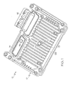
- the reference numeral 10 generally designates an ECM according to this invention.
- the ECM 10 comprises a housing 12 supporting a printed circuit board 14 on which are mounted an number of integrated circuit and discrete electronic devices 14a, including a microprocessor-based controller for executing engine/powertrain control and diagnostic algorithms.
- Input signals, including sensor signals, and output signals are routed to the circuit board 14 through a pair of molded plastic connectors 16 (only one of which is shown in FIG. 1 ) affixed to the housing 12.
- the ECM 10 additionally includes an integral ambient pressure sensor 18 that senses the pressure of ambient air external to the housing 12 and electrically interfaces directly with the circuit board 14 enclosed by housing 12.
- the exterior surface of the housing 12 is provided with a series of raised fins 13 for improved heat dissipation, and the ambient pressure sensor 18 is preferably nestled among the fins 13 as shown to protect the ambient pressure sensor 18 from damage when the housing 12 contacts other objects.
Landscapes
- Physics & Mathematics (AREA)
- General Physics & Mathematics (AREA)
- Chemical & Material Sciences (AREA)
- Analytical Chemistry (AREA)
- Measuring Fluid Pressure (AREA)
Abstract
Description
- The present invention relates to engine control modules for vehicles, and more particularly to a sealed engine control module with an integral ambient air pressure sensor.
- A modem motor vehicle powered by an internal combustion engine is equipped with an engine control module (ECM) for controlling various engine operational parameters such as spark timing, fuel injection, valve timing, emission controls, and so on. The algorithms for carrying out these control functions are based in part on current atmospheric conditions such as ambient air pressure and temperature, and measures of these and other parameters are ordinarily obtained from discrete sensors. In certain instances, the sensors can be mounted on a circuit board within the ECM to minimize system cost, but parameters such as ambient air pressure cannot be reliably sensed inside the ECM, particularly in applications where the housing of the ECM is environmentally-sealed. Accordingly, the ambient air pressure is ordinarily measured with a wired external sensor coupled to the ECM via its wiring harness. For reduced system cost, however, it would be desirable to obtain a reliable measure of ambient air pressure while avoiding the increased expense associated with a wired external sensor.
- The present invention is directed to an improved ECM including an environmentally-sealed housing and an integral air pressure sensor mounted directly on the housing for providing a reliable measure of atmospheric air pressure to a control circuit mounted within the housing. The sensor is mounted on an inboard face of the housing, and includes a sensor element, a body portion and a riser portion. The sensor element is mounted in the body portion, and the riser portion protrudes through an opening in the housing to couple the sensor element to atmospheric air pressure outside the housing. The body portion is sealingly secured to the inboard face of the housing, and a set of conductor pins molded into the body portion extend inward to engage a circuit board enclosed by the housing, and thereby directly couple the sensor element to the ECM's control circuit. The top of the riser portion is capped by a splash-proof lid that prevents water intrusion in applications where the ECM is mounted in an environmentally-exposed location.
- The engine control module, comprises a housing, a circuit board enclosed within said housing and supporting control module circuitry, an opening in the housing in alignment with said circuit board. It further comprises an air pressure sensor mounted on an inboard face of said housing about said opening, said air pressure sensor including a body portion sealingly secured to the inboard face of said housing, a sensing element mounted in a recess formed on an inboard face of said body portion, a riser portion extending outboard of said body portion and protruding through said opening, a central axial bore extending through said body and riser portions to couple said sensor element to atmospheric air pressure outside the housing, and a set of inwardly-depending conductive terminals that engage said circuit board and electrically couple said sensing element to said control module circuitry.The air pressure sensor includes a splash-proof lid capping an exposed end of said riser portion to prevent water intrusion into said central axial bore.An outboard face of said housing includes a series of raised fins adjacent said opening, and said riser portion and splash-proof lid are nestled among said fins such that the fins shield the riser portion and splash-proof lid from damage when said housing contacts other objects. The engine control module further comprises a trough formed on an outboard face of the body portion of said air pressure sensor surrounding said riser portion, a raised shoulder formed on the inboard face of said housing surrounding said opening and nesting in said trough of said air pressure sensor and, an adhesive sealant disposed in said troug to environmentally seal said sensor to said housing around said opening.The inwardly-depending conductive terminals of said air pressure sensor have compliant terminations to provide a solderless electrical coupling between said conductive terminals and said circuit board.The inboard face of said housing includes a pedestal adjacent said air pressure sensor to support said circuit board in the vicinity of said compliant terminations.The sensing element is mounted on a sensor circuit board, said sensor circuit board is mounted in the recess of said body portion, and said conductive terminals are electrically coupled to said sensor circuit board. The engine control module may further comprise a cover sealingly secured to the inboard face of said body portion about said recess to isolate said sensor element from an interior volume of said housing.
-
-
FIG. 1 is an isometric view of an ECM with an integral ambient air pressure sensor according to this invention. -
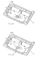
FIGS. 2A is an isometric interior view of a housing-half of the ECM ofFIG. 1 , without the integral ambient air pressure sensor. -
FIG. 2B is an isometric interior view of the housing-half ofFIG. 1 , but with the integral ambient air pressure sensor. -
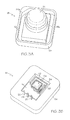
FIGS. 3A is an isometric top view of the integral ambient air pressure sensor ofFIGS. 1 and2B . -
FIG. 3B is an isometric bottom view of the integral ambient air pressure sensor ofFIGS. 1 and2B . -
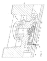
FIG. 4 is an isometric partial cross-sectional view of the ECM ofFIG. 1 . - Referring to the drawings, and particularly to
FIG. 1 , thereference numeral 10 generally designates an ECM according to this invention. In general, the ECM 10 comprises ahousing 12 supporting a printedcircuit board 14 on which are mounted an number of integrated circuit and discrete electronic devices 14a, including a microprocessor-based controller for executing engine/powertrain control and diagnostic algorithms. Input signals, including sensor signals, and output signals are routed to thecircuit board 14 through a pair of molded plastic connectors 16 (only one of which is shown inFIG. 1 ) affixed to thehousing 12. And according to the present invention, theECM 10 additionally includes an integralambient pressure sensor 18 that senses the pressure of ambient air external to thehousing 12 and electrically interfaces directly with thecircuit board 14 enclosed byhousing 12. In a typical application, the exterior surface of thehousing 12 is provided with a series of raised fins 13 for improved heat dissipation, and theambient pressure sensor 18 is preferably nestled among the fins 13 as shown to protect theambient pressure sensor 18 from damage when thehousing 12 contacts other objects. - The
housing 12 ofECM 10 typically comprises a pair of die-cast metal halves, andFIGS. 2A-2B illustrate the interior face of thehousing half 12a seen in the view ofFIG. 1 , but with theconnector 16 removed. Of pertinence to the present invention, a central portion of thehousing half 12a (i.e., a portion overlapping the circuit board 14) is provided with anopening 20 surrounded by a raisedinterior shoulder 22; seeFIG. 2A . - As best seen in
FIGS. 3A-3B and 4 , thesensor 18 includes asensor element 18a, abody portion 18b in which thesensor element 18a is mounted, and ariser portion 18c. Theriser portion 18c extends out of thebody portion 18b, and is capped by a splash-proof lid 24. Referring again toFIGS. 1 and 2A-2B , theriser portion 18c protrudes though the housing opening 20, andbody portion 18b sealingly engages the raisedshoulder 22 ofhousing half 12a to form an environmental seal around the opening 20. Thebody portion 18b is seen in the interior view ofFIG. 2B , and the splash-proof lid 24 is seen in the exterior view ofFIG. 1 . - As shown in
FIGS. 2B and3B , thesensor 18 additionally includes a set ofcompliant terminals 26 for electrically coupling thesensor element 18a to the ECM'scircuit board 14. As shown inFIG. 4 , theterminals 26 are insert molded in thesensor body portion 18b, and preferably havecompliant terminations 26a (eye-of-needle, for example) to enable solder-less connection with thecircuit board 14. Thecircuit board 14, in turn, is supported on a peripheralinterior ledge 28 ofhousing half 12a, and a distributed set ofpedestals 30 within theperipheral ledge 28. Significantly, the opening 20 and raisedshoulder 22 are placed adjacent to apedestal 30 to firmly support thecircuit board 14 in the vicinity of thesensor 18 and maintain a prescribed distance betweensensor 18 andcircuit board 14 whencircuit board 14 is mounted inhousing half 12a. - Referring again to
FIG. 3A , it will be seen that thebody portion 18b andriser portion 18c ofsensor 18 are molded as a unitary plastic part. The top face ofbody portion 18b includes aperipheral trough 32 surrounding theriser portion 18c that dimensionally corresponds to the raisedshoulder 22 ofhousing half 12a. When thesensor 18 is mounted on thehousing half 12a as shown inFIG. 2B , the raisedshoulder 22 nests in thetrough 32, as shown in the partial cross-sectional view ofFIG. 4 . Prior to such mounting of thesensor 18, however, a sealant/adhesive material is dispensed into thetrough 32 to both secure thesensor 18 to thehousing half 12a, and form an environmental seal around thehousing opening 20. As also seen inFIGS. 2A and3A , the raisedshoulder 22 and thetrough 32 are asymmetrically notched as respectively indicated by thereference numerals sensor 18 from being mounted in an incorrect orientation. - Referring particularly to
FIGS. 3B and4 , the bottom (i.e., inboard-facing) face of thesensor body portion 18b includes acentral recess 34 within the outline oftrough 32 for accommodating thesensor element 18a. In the illustrated embodiment, thesensor element 18a is implemented as a three-terminal device, including asensor chip 36 and various discrete and integrated signal processing devices mounted on aceramic substrate 38. To prevent pressure within the sealedECM 10 from influencing the sensed ambient air pressure, the inboard side ofsensor element 18a is sealed with acover 40 that nests in aperipheral trough 42 surrounding thecentral recess 34. And as with thetrough 32, a sealant/adhesive material is dispensed into thetrough 42 to both secure thecover 40 to thesensor body portion 18b, and form an environmental seal around thecentral recess 34. -
FIG. 4 illustrates theECM 10 with installedambient pressure sensor 18. Accordingly, thebody portion 18b ofsensor 18 is sealingly secured to the raisedinterior shoulder 22 ofhousing half 12a, theriser portion 18c protrudes through thehousing opening 20, and thecompliant terminations 26a ofsensor terminals 26 are received in plated openings provided in the ECM'scircuit board 14. In the illustrated embodiment, the sensorelement circuit board 38 is ceramic, and the insert moldedterminals 26 are electrically coupled to bond sites formed on the face of thecircuit board 38 by wirebonding. Alternately, the sensor circuitry can be mounted on a printed circuit board similar to theECM circuit board 14, and in that case, the insert moldedterminals 26 may be provided with compliant terminations for solderless interconnection with the sensor element circuit board. - As also shown in
FIG. 4 , thesensor 18 includes acentral opening 44 extending though the body andriser portions recess 32, and therefore the outboard face of thesensor element 18a, to atmospheric air outside theECM 10. The top of theriser portion 18c is stepped radially-inward to accommodate the splash-proof lid 24 within the diameter of thehousing opening 20, and thelid 24 is retained onriser portion 18c by a set ofcomplementary interleaving tabs riser portion 18c and thelid 24, respectively. Thelid 24 also has an integral axially-dependinginterior post 50 in alignment with thecentral opening 44 ofsensor 18. The axial dimension of thepost 50 is such that it blocks water intrusion into thecentral opening 44, while maintaining open communication between thecentral opening 44 and atmospheric air pressure in and around thelid 24. - In summary, the
ECM 10 of the present invention provides a cost-effective alternative to the conventional approach of using a discrete wired sensor to develop reliable ambient pressure input data for engine control algorithms implemented by the ECM control circuits.
Claims (8)
- An engine control module (10), comprising:a housing (12);a circuit board (14) enclosed within said housing (12) and supporting control module circuitry (14a);an opening (20) in the housing (12a) in alignment with said circuit board (14); andan air pressure sensor (18) mounted on an inboard face of said housing (12a) about said opening (20), said air pressure sensor (20) including a body portion (18b) sealingly secured to the inboard face of said housing (12a), a sensing element (18a) mounted in a recess (32) formed on an inboard face of said body portion (18b), a riser portion (18c) extending outboard of said body portion (18b) and protruding through said opening (20), a central axial bore (44) extending through said body and riser portions (18b, 18c) to couple said sensor element (18a) to atmospheric air pressure outside the housing (12), and a set of inwardly-depending conductive terminals (26) that engage said circuit board (14) and electrically couple said sensing element (18a) to said control module circuitry (14a).
- The engine control module of claim 1, where:said air pressure sensor (18) includes a splash-proof lid (24) capping an exposed end of said riser portion (18c) to prevent water intrusion into said central axial bore (44).
- The engine control module of claim 2, where:an outboard face of said housing (18) includes a series of raised fins (13) adjacent said opening (20), and said riser portion (18c) and splash-proof lid (24) are nestled among said fins (13) such that the fins (13) shield the riser portion (18c) and splash-proof lid (24) from damage when said housing (12) contacts other objects.
- The engine control module as set in any of the preceding claims, further comprising:a trough (32) formed on an outboard face of the body portion (18b) of said air pressure sensor (18) surrounding said riser portion (18c);a raised shoulder (22) formed on the inboard face of said housing (12a) surrounding said opening (20) and nesting in said trough (32) of said air pressure sensor (18); andan adhesive sealant disposed in said trough (32) to environmentally seal said sensor (18) to said housing (12) around said opening (20).
- The engine control module as set in any of the preceding claims, where:the inwardly-depending conductive terminals (26) of said air pressure sensor (18) have compliant terminations (26a) to provide a solderless electrical coupling between said conductive terminals (26) and said circuit board (14).
- The engine control module of claim 5, where:said inboard face of said housing (12a) includes a pedestal (30) adjacent said air pressure sensor (18) to support said circuit board (14) in the vicinity of said compliant terminations (26a).
- The engine control module as set in any of the preceding claims, where:said sensing element (18a) is mounted on a sensor circuit board (38), said sensor circuit board (38) is mounted in the recess (32) of said body portion (18b), and said conductive terminals (26) are electrically coupled to said sensor circuit board (38).
- The engine control module of claim 7, further comprising:a cover (40) sealingly secured to the inboard face of said body portion (18b) about said recess (32) to isolate said sensor element (18a) from an interior volume of said housing (12).
Applications Claiming Priority (1)
| Application Number | Priority Date | Filing Date | Title |
|---|---|---|---|
| US12/709,644 US8375778B2 (en) | 2010-02-22 | 2010-02-22 | Sealed engine control module with integral ambient air pressure sensor |
Publications (2)
| Publication Number | Publication Date |
|---|---|
| EP2365308A2 true EP2365308A2 (en) | 2011-09-14 |
| EP2365308A3 EP2365308A3 (en) | 2014-10-01 |
Family
ID=44314940
Family Applications (1)
| Application Number | Title | Priority Date | Filing Date |
|---|---|---|---|
| EP11152364.3A Withdrawn EP2365308A3 (en) | 2010-02-22 | 2011-01-27 | Sealed engine control module with integral ambient air pressure sensor |
Country Status (2)
| Country | Link |
|---|---|
| US (1) | US8375778B2 (en) |
| EP (1) | EP2365308A3 (en) |
Cited By (2)
| Publication number | Priority date | Publication date | Assignee | Title |
|---|---|---|---|---|
| AT518125A1 (en) * | 2015-11-16 | 2017-07-15 | Melecs Ews Gmbh & Co Kg | Housing cover for an electrical machine |
| WO2018224278A1 (en) * | 2017-06-08 | 2018-12-13 | Robert Bosch Gmbh | Micromechanical pressure sensor assembly and method for producing a micromechanical pressure sensor assembly |
Families Citing this family (4)
| Publication number | Priority date | Publication date | Assignee | Title |
|---|---|---|---|---|
| JP6275431B2 (en) * | 2013-09-18 | 2018-02-07 | アルプス電気株式会社 | Pressure detecting device and intake pressure measuring device using the same |
| JP6358145B2 (en) * | 2015-03-30 | 2018-07-18 | 株式会社デンソー | Electronic control device and method of manufacturing electronic control device |
| FR3081672B1 (en) | 2018-05-22 | 2021-04-09 | A Raymond Et Cie | PROTECTION BOX FOR AN ELECTRONIC DEVICE |
| JP7826978B2 (en) * | 2023-02-28 | 2026-03-10 | 株式会社デンソー | Electronic control unit |
Family Cites Families (6)
| Publication number | Priority date | Publication date | Assignee | Title |
|---|---|---|---|---|
| DE4334123C2 (en) * | 1993-10-07 | 2002-12-19 | Bosch Gmbh Robert | pressure sensor |
| DE10022124B4 (en) * | 2000-05-06 | 2010-01-14 | Wabco Gmbh | Electronic control unit |
| JP2002082009A (en) * | 2000-06-30 | 2002-03-22 | Denso Corp | Pressure sensor |
| US6722205B2 (en) * | 2002-06-24 | 2004-04-20 | Honeywell International, Inc. | Unitary pressure sensor housing and assembly |
| JP2004279091A (en) * | 2003-03-13 | 2004-10-07 | Denso Corp | Pressure sensor |
| DE102008004358A1 (en) * | 2008-01-15 | 2009-07-16 | Robert Bosch Gmbh | Pressure compensation unit |
-
2010
- 2010-02-22 US US12/709,644 patent/US8375778B2/en active Active
-
2011
- 2011-01-27 EP EP11152364.3A patent/EP2365308A3/en not_active Withdrawn
Non-Patent Citations (1)
| Title |
|---|
| None |
Cited By (5)
| Publication number | Priority date | Publication date | Assignee | Title |
|---|---|---|---|---|
| AT518125A1 (en) * | 2015-11-16 | 2017-07-15 | Melecs Ews Gmbh & Co Kg | Housing cover for an electrical machine |
| AT518125B1 (en) * | 2015-11-16 | 2020-01-15 | Melecs Ews Gmbh & Co Kg | Housing cover for an electrical machine |
| WO2018224278A1 (en) * | 2017-06-08 | 2018-12-13 | Robert Bosch Gmbh | Micromechanical pressure sensor assembly and method for producing a micromechanical pressure sensor assembly |
| CN111033204A (en) * | 2017-06-08 | 2020-04-17 | 罗伯特·博世有限公司 | Micromechanical pressure sensor assembly and method for producing a micromechanical pressure sensor assembly |
| US11397121B2 (en) | 2017-06-08 | 2022-07-26 | Robert Bosch Gmbh | Micromechanical pressure sensor system and method for manufacturing a micromechanical pressure sensor system |
Also Published As
| Publication number | Publication date |
|---|---|
| US20110203359A1 (en) | 2011-08-25 |
| EP2365308A3 (en) | 2014-10-01 |
| US8375778B2 (en) | 2013-02-19 |
Similar Documents
| Publication | Publication Date | Title |
|---|---|---|
| US8375778B2 (en) | Sealed engine control module with integral ambient air pressure sensor | |
| US8192078B2 (en) | Device for recording the pressure and the temperature in an intake manifold of an internal combustion engine | |
| US7478560B2 (en) | Sensor apparatus responsive to pressure and temperature within a vessel | |
| US8112196B2 (en) | Electronic control unit and vehicle behavior control device | |
| US9006847B2 (en) | Sensor module for accommodating a pressure sensor chip and for installation into a sensor housing | |
| US9316170B2 (en) | Controller integrated fuel pump module | |
| CN101558285B (en) | Method for manufacturing a mounting element with an angle sensor | |
| CN111165081B (en) | electronic control unit | |
| CN105027363B (en) | The connection method of circuit fixed component, circuit module and circuit module | |
| EP1975572B1 (en) | Sensor apparatus | |
| EP1618770B1 (en) | Electronic control module for a removable connector and methods of assembling same | |
| CN107431306A (en) | Electric coupler set member, electronic unit and assemble method | |
| US7221149B2 (en) | Moving object detection device | |
| CN103748976B (en) | Sensor with unique electrical support | |
| CN110383960B (en) | Electronic control module and method for manufacturing electronic control module | |
| US12285994B2 (en) | Sensor module, particularly for measuring ambient temperature | |
| US20110273854A1 (en) | Magnetic Field Sensor | |
| EP1546660B1 (en) | Non-contacting sensor multichip module with integral heat-sinks | |
| JP6520636B2 (en) | Physical quantity sensor subassembly and physical quantity measuring device | |
| EP1607618A2 (en) | Fuel supply apparatus | |
| US5714409A (en) | Method and apparatus for packaging a vehicle sensor and integrated circuit chip | |
| US12066303B2 (en) | Physical quantity sensor-fixing structure | |
| JP3587425B2 (en) | Intake system control device for internal combustion engine | |
| US20190353510A1 (en) | Electronics unit for a flow meter | |
| JP3482583B2 (en) | Waterproof structure of pressure detector |
Legal Events
| Date | Code | Title | Description |
|---|---|---|---|
| PUAI | Public reference made under article 153(3) epc to a published international application that has entered the european phase |
Free format text: ORIGINAL CODE: 0009012 |
|
| AK | Designated contracting states |
Kind code of ref document: A2 Designated state(s): AL AT BE BG CH CY CZ DE DK EE ES FI FR GB GR HR HU IE IS IT LI LT LU LV MC MK MT NL NO PL PT RO RS SE SI SK SM TR |
|
| AX | Request for extension of the european patent |
Extension state: BA ME |
|
| PUAL | Search report despatched |
Free format text: ORIGINAL CODE: 0009013 |
|
| AK | Designated contracting states |
Kind code of ref document: A3 Designated state(s): AL AT BE BG CH CY CZ DE DK EE ES FI FR GB GR HR HU IE IS IT LI LT LU LV MC MK MT NL NO PL PT RO RS SE SI SK SM TR |
|
| AX | Request for extension of the european patent |
Extension state: BA ME |
|
| RIC1 | Information provided on ipc code assigned before grant |
Ipc: G01L 19/06 20060101ALI20140825BHEP Ipc: G01L 9/00 20060101AFI20140825BHEP Ipc: G01L 19/14 20060101ALI20140825BHEP |
|
| STAA | Information on the status of an ep patent application or granted ep patent |
Free format text: STATUS: THE APPLICATION IS DEEMED TO BE WITHDRAWN |
|
| 18D | Application deemed to be withdrawn |
Effective date: 20150402 |