EP1607618A2 - Fuel supply apparatus - Google Patents
Fuel supply apparatus Download PDFInfo
- Publication number
- EP1607618A2 EP1607618A2 EP04030667A EP04030667A EP1607618A2 EP 1607618 A2 EP1607618 A2 EP 1607618A2 EP 04030667 A EP04030667 A EP 04030667A EP 04030667 A EP04030667 A EP 04030667A EP 1607618 A2 EP1607618 A2 EP 1607618A2
- Authority
- EP
- European Patent Office
- Prior art keywords
- fuel
- fuel tank
- electronic circuit
- supply apparatus
- circuit section
- Prior art date
- Legal status (The legal status is an assumption and is not a legal conclusion. Google has not performed a legal analysis and makes no representation as to the accuracy of the status listed.)
- Withdrawn
Links
Images


Classifications
-
- F—MECHANICAL ENGINEERING; LIGHTING; HEATING; WEAPONS; BLASTING
- F02—COMBUSTION ENGINES; HOT-GAS OR COMBUSTION-PRODUCT ENGINE PLANTS
- F02M—SUPPLYING COMBUSTION ENGINES IN GENERAL WITH COMBUSTIBLE MIXTURES OR CONSTITUENTS THEREOF
- F02M37/00—Apparatus or systems for feeding liquid fuel from storage containers to carburettors or fuel-injection apparatus; Arrangements for purifying liquid fuel specially adapted for, or arranged on, internal-combustion engines
- F02M37/04—Feeding by means of driven pumps
- F02M37/08—Feeding by means of driven pumps electrically driven
- F02M37/10—Feeding by means of driven pumps electrically driven submerged in fuel, e.g. in reservoir
Definitions
- the present invention relates to a fuel supply apparatus.
- a Japanese Patent No. 3371409 issued on November 22, 2002 exemplifies a previously proposed fuel supply apparatus which is equipped with a fuel pump in an integrated fashion and is attached as a cover (or, a lid) of a fuel tank so as to cover and close an opening of a top (or, upper) surface of the fuel tank.
- the fuel pump is disposed inside the fuel tank and serves to suck fuel inside the fuel tank and deliver the sucked fuel to outside of the fuel tank.
- a top surface of this previously proposed fuel supply apparatus has a recess portion.
- a fuel pump controller acting as a control circuit for the fuel pump is inserted into the recess portion from outside of the fuel tank in a removable fashion.
- the pump controller can be inserted/removed from/to outside of the fuel tank.
- the recess portion for inserting the fuel pump controller needs to be produced at the top surface of the cover.
- a connector for electrically connecting the fuel pump controller to the fuel pump also needs to be provided to a deep part of the recess portion.
- an object of the present invention to provide a fuel supply apparatus which is capable of reducing expense in time and effort for manufacturing and reducing a cost of manufacturing when an electronic circuits which includes at least a pump controlling section that controls a motion of a fuel pump is installed to the fuel supply apparatus.
- a fuel supply apparatus comprising: a fuel pump disposed in a fuel tank; and a fuel tank cover member disposed at a top portion of the fuel tank, an electronic circuit section being fixedly integrated into the fuel tank cover member, the electronic circuit section including a pump controlling section that controls the fuel pump.
- Fig. 1 is a side view of a fuel supply apparatus in a preferred embodiment according to the present invention.
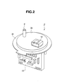
- Fig. 2 is a perspective view of a fuel tank cover member in the fuel supply apparatus shown in Fig. 1.
- Fig. 3 is a perspective view of an electronic circuit section which is integrated into the fuel tank cover member included in the fuel supply apparatus in the embodiment according to the present invention.
- Fig. 1 is a side view largely representing a configuration of the fuel supply apparatus which is installed inside the fuel tank.
- Fig. 2 is a perspective view representing a fuel tank cover member in the fuel supply apparatus.
- Fig. 3 is a perspective view of an electronic circuit section which is integrated into the fuel tank cover member.
- a fuel supply apparatus 1 includes a fuel pump module 2 and a fuel tank cover member 3 (namely, a cover member for a fuel tank).
- Fuel pump module 2 is installed (or, disposed) in contact with a bottom surface 4b of a fuel tank 4.
- Fuel pump module 2 includes, for example, a fuel pump 5 and a liquid-level sensor 6 in an integrated fashion (namely, fuel pump 5 and liquid-level sensor 6 are integrated into fuel pump module 2).
- Fuel pump 5 sucks a fuel 7 reserved within fuel tank 4 and delivers (or discharges) the sucked fuel from an outlet port 5a.
- the fuel discharged from outlet port 5a is transferred to outside of fuel tank 4, namely, to a fuel injection valve of an internal combustion engine via a tube 8 and a pipe 9 which is projecting from an upper surface of fuel tank cover member 3.
- This fuel pump 5 is an electrically powered pump integrated with a motor. Operation of fuel pump 5 is controlled by a pump controlling section (not shown) installed in an electronic circuit section 13 as will be described later.
- Liquid-level sensor 6 includes an arm 11 which can swing, and a float 12 connected to an end of arm 11. Liquid-level sensor 6 detects a remaining quantity of fuel 7 inside fuel tank 4 by detecting a swing angle of arm 11 in accordance with a position of float 12 which is floating on fuel 7. For example, if a resistance of a predetermined electronic circuit is configured so as to vary according to the swing angle of arm 11, liquid-level sensor 6 can detect the swing angle of arm 11, namely, a height of a liquid level of fuel 7 by detecting the resistance.
- Fuel tank cover member 3 is attached to fuel tank 4 so as to cover and close (or, put a lid on) an opening portion 4a defined by a top (or, upper) surface of fuel tank 4 (i.e., an opening portion 4a in a top portion of fuel tank 4).
- This fuel tank cover member 3 includes a base portion 3a whose thickness is predetermined (for example, several centimeters), a flange 3b overhanging around (or, surrounding) base portion 3a by a predetermined width (for example, several centimeters), and electronic circuit section 13 which is projecting and extending from underside of base portion 3a to a downward direction, namely into inside of fuel tank 4.
- pipe 9 for delivering the fuel and a connector 16 for attaining an electrical connection between inside and outside of fuel tank 4 are provided to an upper surface of base portion 3a exposed to outside of fuel tank 4.
- Electronic circuit section 13 includes electrical circuits which control electrical equipments (namely, fuel pump 5 and liquid-level sensor 6 and so on) inside fuel tank 4.
- electronic circuit section 13 includes at least a pump controlling section (not shown) which controls (a motion of) fuel pump 5 and a detection processing section (not shown) which processes signals detected by liquid-level sensor 6.
- electronic circuit section 13 is electrically connected to circuits installed inside fuel pump module 2 via a harness 10 within fuel tank 4. Hence, motion control signals from electronic circuit section 13 to fuel pump 5 and signals detected by liquid-level sensor 6 are transmitted through harness 10.
- electronic circuit section 13 is electrically connected to electrical circuits disposed outside fuel tank 4 (for example, ECU) via connector 16 installed at upper side of electronic circuit section 13.
- fuel tank cover member 3 is molded, in an integrated fashion, by resin (insulation resin) which coats (or, wraps) electronic circuit section 13 of Fig. 3. That is to say, almost all surface of electronic circuit section 13 is coated (or, covered) with the resin which forms base portion 3a, flange 3b and others of fuel tank cover member 3, although some electrical connection parts such as connector 16 are not coated.
- resin insulation resin
- the recess portion for inserting the electronic circuit section in a removable fashion needs to be produced on the fuel tank cover member, and (for example) a connector for electrically connecting the electronic circuit section to the fuel pump also needs to be provided to the deep part of the recess portion.
- electronic circuit section 13 is integrated into and fixed into fuel tank cover member 3 (i.e., is fixedly integrated into fuel tank cover member 3).
- recess portion and connector are not necessary in this embodiment. Thereby, an expense in time and effort for manufacturing is reduced and a cost of manufacturing can be reduced.
- electronic circuit section 13 is molded into and integrated into fuel tank cover member 3 by resin forming. Hence, (for example) a seal member for preventing atmosphere within fuel tank 4 or outside air from entering into electronic circuit section 13 is not necessary to be attached separately. Thereby, an expense in time and effort for manufacturing is reduced and a cost of manufacturing can be reduced.
- electronic circuit section 13 is disposed within fuel tank 4 in this embodiment.
- fuel tank 4 can protect electronic circuit section 13 from receiving a damage, even if, for example, a vehicle collision happens.
- fuel pump module 2 and fuel tank cover member 3 are configured separately each other.
- a fuel tank cover member is configured as a fuel pump module which includes a fuel pump and others. This second embodiment can be also achieved according to the present invention and, has same advantages as those of the above-described (first) embodiment.
- the board of the electronic circuit section is disposed in a vertical direction (i.e., a direction along with the surface of the board is a vertical direction).
- an end portion of the electronic circuit section is disposed at a lower position of the fuel tank.
- the harness between the electronic circuit section and the electrical equipments inside the fuel tank can be formed in a shorter shape.
- a layout for these components is more flexible than a case where the board of the electronic circuit section is disposed in a horizontal direction or an inclined direction.
- the fuel tank cover member can be configured (or, designed) to be more compact and lightweight.
- the electronic circuit section is molded (or, covered) after the electronic circuit section is equipped with the connectors for electrically connecting the electronic circuit section to the circuits outside the fuel tank.
- the connection is more assuredly performed, and an expense in time and effort for manufacturing and a cost of manufacturing can be more reduced than a case where the connectors are installed in the electronic circuit section after the electronic circuit section is molded (or, covered).
Landscapes
- Engineering & Computer Science (AREA)
- Chemical & Material Sciences (AREA)
- Combustion & Propulsion (AREA)
- Mechanical Engineering (AREA)
- General Engineering & Computer Science (AREA)
- Cooling, Air Intake And Gas Exhaust, And Fuel Tank Arrangements In Propulsion Units (AREA)
Abstract
In a fuel supply apparatus (1) a fuel pump (5) is disposed in a fuel
tank (4) and a fuel tank cover member (3) is disposed at a top portion
of the fuel tank. An electronic circuit section (13) is fixedly
integrated into the fuel tank cover member (3), and the electronic
circuit section (13) includes a pump controlling section that controls
the fuel pump (5). Moreover, the electronic circuit section (13) is
molded into the fuel tank cover member (3) by using resin.
Description
The present invention relates to a fuel supply apparatus.
Various kinds of fuel supply apparatuses have been
previously proposed. A Japanese Patent No. 3371409
issued on November 22, 2002 exemplifies a previously
proposed fuel supply apparatus which is equipped with a
fuel pump in an integrated fashion and is attached as a
cover (or, a lid) of a fuel tank so as to cover and close an
opening of a top (or, upper) surface of the fuel tank. The
fuel pump is disposed inside the fuel tank and serves to
suck fuel inside the fuel tank and deliver the sucked fuel to
outside of the fuel tank.
Furthermore, a top surface of this previously
proposed fuel supply apparatus has a recess portion. A fuel
pump controller acting as a control circuit for the fuel pump
is inserted into the recess portion from outside of the fuel
tank in a removable fashion.
In the previously proposed fuel supply apparatus
disclosed in the above-described Japanese Patent, the
pump controller can be inserted/removed from/to outside
of the fuel tank. However, the recess portion for inserting
the fuel pump controller needs to be produced at the top
surface of the cover. Moreover, a connector for electrically
connecting the fuel pump controller to the fuel pump also
needs to be provided to a deep part of the recess portion.
Hence, there is the problem that a cost of manufacturing is
increased due to increased expense in time and effort for
manufacturing the above-described previously proposed
fuel supply apparatus.
It is, therefore, an object of the present
invention to provide a fuel supply apparatus which is
capable of reducing expense in time and effort for
manufacturing and reducing a cost of manufacturing when
an electronic circuits which includes at least a pump
controlling section that controls a motion of a fuel pump is
installed to the fuel supply apparatus.
According to one aspect of the present invention,
there is provided a fuel supply apparatus, comprising: a
fuel pump disposed in a fuel tank; and a fuel tank cover
member disposed at a top portion of the fuel tank, an
electronic circuit section being fixedly integrated into the
fuel tank cover member, the electronic circuit section
including a pump controlling section that controls the fuel
pump.
The other objects and features of this invention
will become understood from the following description with
reference to the accompanying drawings.
Fig. 1 is a side view of a fuel supply apparatus in
a preferred embodiment according to the present invention.
Fig. 2 is a perspective view of a fuel tank cover
member in the fuel supply apparatus shown in Fig. 1.
Fig. 3 is a perspective view of an electronic
circuit section which is integrated into the fuel tank cover
member included in the fuel supply apparatus in the
embodiment according to the present invention.
Reference will hereinafter be made to the
drawings in order to facilitate a better understanding of the
present invention. In this preferred embodiment according
to the present invention, a fuel supply apparatus which is
installed inside a fuel tank for the vehicle equipped with an
internal combustion engine is exemplified.
Fig. 1 is a side view largely representing a
configuration of the fuel supply apparatus which is installed
inside the fuel tank. Fig. 2 is a perspective view
representing a fuel tank cover member in the fuel supply
apparatus. Fig. 3 is a perspective view of an electronic
circuit section which is integrated into the fuel tank cover
member.
A fuel supply apparatus 1 according to this
embodiment includes a fuel pump module 2 and a fuel tank
cover member 3 (namely, a cover member for a fuel tank).
Liquid-level sensor 6 includes an arm 11 which
can swing, and a float 12 connected to an end of arm 11.
Liquid-level sensor 6 detects a remaining quantity of fuel 7
inside fuel tank 4 by detecting a swing angle of arm 11 in
accordance with a position of float 12 which is floating on
fuel 7. For example, if a resistance of a predetermined
electronic circuit is configured so as to vary according to
the swing angle of arm 11, liquid-level sensor 6 can detect
the swing angle of arm 11, namely, a height of a liquid
level of fuel 7 by detecting the resistance.
Fuel tank cover member 3 is attached to fuel
tank 4 so as to cover and close (or, put a lid on) an
opening portion 4a defined by a top (or, upper) surface of
fuel tank 4 (i.e., an opening portion 4a in a top portion of
fuel tank 4). This fuel tank cover member 3 includes a base
portion 3a whose thickness is predetermined (for example,
several centimeters), a flange 3b overhanging around (or,
surrounding) base portion 3a by a predetermined width (for
example, several centimeters), and electronic circuit
section 13 which is projecting and extending from
underside of base portion 3a to a downward direction,
namely into inside of fuel tank 4. Moreover, pipe 9 for
delivering the fuel and a connector 16 for attaining an
electrical connection between inside and outside of fuel
tank 4 are provided to an upper surface of base portion 3a
exposed to outside of fuel tank 4.
As shown in Fig. 3, various kinds of circuit
components 15 and connector 16 and others are mounted
on a surface or an edge of a (circuit) board 14 in electronic
circuit section 13. Electronic circuit section 13 includes
electrical circuits which control electrical equipments
(namely, fuel pump 5 and liquid-level sensor 6 and so on)
inside fuel tank 4. In this embodiment, electronic circuit
section 13 includes at least a pump controlling section (not
shown) which controls (a motion of) fuel pump 5 and a
detection processing section (not shown) which processes
signals detected by liquid-level sensor 6. In addition,
electronic circuit section 13 is electrically connected to
circuits installed inside fuel pump module 2 via a harness
10 within fuel tank 4. Hence, motion control signals from
electronic circuit section 13 to fuel pump 5 and signals
detected by liquid-level sensor 6 are transmitted through
harness 10. On the other hand, electronic circuit section 13
is electrically connected to electrical circuits disposed
outside fuel tank 4 (for example, ECU) via connector 16
installed at upper side of electronic circuit section 13.
In this embodiment, as shown in Fig. 2, fuel tank
cover member 3 is molded, in an integrated fashion, by
resin (insulation resin) which coats (or, wraps) electronic
circuit section 13 of Fig. 3. That is to say, almost all
surface of electronic circuit section 13 is coated (or,
covered) with the resin which forms base portion 3a, flange
3b and others of fuel tank cover member 3, although some
electrical connection parts such as connector 16 are not
coated.
In the related art, the recess portion for
inserting the electronic circuit section in a removable
fashion needs to be produced on the fuel tank cover
member, and (for example) a connector for electrically
connecting the electronic circuit section to the fuel pump
also needs to be provided to the deep part of the recess
portion. However, in this embodiment as described above,
electronic circuit section 13 is integrated into and fixed into
fuel tank cover member 3 (i.e., is fixedly integrated into
fuel tank cover member 3). Hence, such recess portion and
connector are not necessary in this embodiment. Thereby,
an expense in time and effort for manufacturing is reduced
and a cost of manufacturing can be reduced.
Moreover, in this embodiment, electronic circuit
section 13 is molded into and integrated into fuel tank
cover member 3 by resin forming. Hence, (for example) a
seal member for preventing atmosphere within fuel tank 4
or outside air from entering into electronic circuit section
13 is not necessary to be attached separately. Thereby, an
expense in time and effort for manufacturing is reduced
and a cost of manufacturing can be reduced.
Furthermore, electronic circuit section 13 is
disposed within fuel tank 4 in this embodiment. Hence, fuel
tank 4 can protect electronic circuit section 13 from
receiving a damage, even if, for example, a vehicle collision
happens.
In the above-described (first) embodiment, fuel
pump module 2 and fuel tank cover member 3 are
configured separately each other. In a second preferred
embodiment, a fuel tank cover member is configured as a
fuel pump module which includes a fuel pump and others.
This second embodiment can be also achieved according to
the present invention and, has same advantages as those
of the above-described (first) embodiment.
The other advantages and preferable technical
issues with respect to the above-described embodiments
will now be explained.
In the fuel supply apparatus according to the
above-described embodiments, it is favorable that the
board of the electronic circuit section is disposed in a
vertical direction (i.e., a direction along with the surface of
the board is a vertical direction). In this case, an end
portion of the electronic circuit section is disposed at a
lower position of the fuel tank. Hence, the harness between
the electronic circuit section and the electrical equipments
inside the fuel tank can be formed in a shorter shape.
Moreover, especially when some components in addition to
the electronic circuit section are installed in the fuel tank
cover member, a layout for these components is more
flexible than a case where the board of the electronic
circuit section is disposed in a horizontal direction or an
inclined direction. Hence, the fuel tank cover member can
be configured (or, designed) to be more compact and
lightweight.
Next, in the fuel supply apparatus according to
the above-described embodiments, it is favorable that the
electronic circuit section is molded (or, covered) after the
electronic circuit section is equipped with the connectors
for electrically connecting the electronic circuit section to
the circuits outside the fuel tank. In this case, the
connection is more assuredly performed, and an expense in
time and effort for manufacturing and a cost of
manufacturing can be more reduced than a case where the
connectors are installed in the electronic circuit section
after the electronic circuit section is molded (or, covered).
This application is based on a prior Japanese
Patent Application No. 2004-179583 filed on June 17, 2004.
The entire contents of this Japanese Patent Application No.
2004-179583 is hereby incorporated by reference.
Although the invention has been described above
with reference to certain embodiments of the invention, the
invention is not limited to the embodiments described
above. Modifications and variations of the embodiments
described above will occur to those skilled in the art in light
of the above teachings. The scope of the invention is
defined with reference to the following claims.
Claims (13)
- A fuel supply apparatus, comprising:a fuel pump (5) disposed in a fuel tank (4); anda fuel tank cover member (3) disposed at a top portion of the fuel tank (4), an electronic circuit section (13) being fixedly integrated into the fuel tank cover member (3), the electronic circuit section (13) including a pump controlling section that controls the fuel pump (5).
- A fuel supply apparatus as claimed in claim 1, further comprising a liquid-level sensor (6) that detects a remaining quantity of fuel (7) inside the fuel tank (4).
- A fuel supply apparatus as claimed in any one of the preceding claims 1 and 2, wherein the electronic circuit section (13) controls an electrical equipment (5, 6) inside the fuel tank (4).
- A fuel supply apparatus as claimed in claim 2, wherein the electronic circuit section (13) includes the pump controlling section and a detection processing section that processes signals detected by the liquid-level sensor (6).
- A fuel supply apparatus as claimed in any one of the preceding claims 1 through 4, wherein the electronic circuit section (13) includes a circuit board (14) and circuit components (15) mounted on the circuit board (14).
- A fuel supply apparatus as claimed in any one of the preceding claims 1 through 5, wherein the fuel tank cover member (3) covers an opening portion (4a) at the top portion of the fuel tank (4).
- A fuel supply apparatus as claimed in any one of the preceding claims 1 through 6, wherein the fuel tank cover member (3) covers an opening portion (4a) defined by a top surface of the fuel tank (4).
- A fuel supply apparatus as claimed in any one of the preceding claims 1 through 7, wherein the fuel tank cover member (3) is provided with a pipe (9) to deliver a fuel and a connector (16) to attain an electrical connection between inside and outside of the fuel tank (4).
- A fuel supply apparatus as claimed in any one of the preceding claims 1 through 8, wherein the electronic circuit section (13) is electrically connected to the fuel pump (5) via a harness (10) within the fuel tank (4).
- A fuel supply apparatus as claimed in any one of the preceding claims 1 through 9, wherein a resin is used in order to integrate and fix the electronic circuit section (13) into the fuel tank cover member (3).
- A fuel supply apparatus as claimed in any one of the preceding claims 1 through 10, wherein the electronic circuit section (13) is fixedly integrated into the fuel tank cover member (3) in such a way that the electronic circuit section (13) is coated with a resin which forms the fuel tank cover member (3).
- A fuel supply apparatus as claimed in any one of the preceding claims 1 through 11, wherein the electronic circuit section (13) is molded into and integrated into the fuel tank cover member (3) by means of resin forming.
- A fuel supply apparatus as claimed in any one of the preceding claims 1 through 12, wherein the electronic circuit section (13) is disposed inside the fuel tank (4).
Applications Claiming Priority (2)
| Application Number | Priority Date | Filing Date | Title |
|---|---|---|---|
| JP2004179583A JP2006002658A (en) | 2004-06-17 | 2004-06-17 | Fuel feeder |
| JP2004179583 | 2004-06-17 |
Publications (1)
| Publication Number | Publication Date |
|---|---|
| EP1607618A2 true EP1607618A2 (en) | 2005-12-21 |
Family
ID=34927982
Family Applications (1)
| Application Number | Title | Priority Date | Filing Date |
|---|---|---|---|
| EP04030667A Withdrawn EP1607618A2 (en) | 2004-06-17 | 2004-12-23 | Fuel supply apparatus |
Country Status (4)
| Country | Link |
|---|---|
| US (1) | US20050281684A1 (en) |
| EP (1) | EP1607618A2 (en) |
| JP (1) | JP2006002658A (en) |
| CN (1) | CN1710270A (en) |
Families Citing this family (10)
| Publication number | Priority date | Publication date | Assignee | Title |
|---|---|---|---|---|
| JP2007118627A (en) * | 2005-10-24 | 2007-05-17 | Yamaha Motor Co Ltd | Fuel tank assembly and saddle riding type vehicle equipped therewith |
| JP2009092014A (en) * | 2007-10-10 | 2009-04-30 | Aisan Ind Co Ltd | Fuel supply device |
| JP5136575B2 (en) * | 2010-03-01 | 2013-02-06 | 株式会社デンソー | Fuel supply device |
| JP5110099B2 (en) * | 2010-02-09 | 2012-12-26 | 株式会社デンソー | Fuel supply device |
| US8869775B2 (en) * | 2010-02-09 | 2014-10-28 | Denso Corporation | Fuel supply apparatus |
| CN104813018B (en) * | 2013-10-21 | 2018-01-09 | 玄谭产业株式会社 | The vehicle fuel pump module of control device is installed |
| CN104150428B (en) * | 2014-08-22 | 2017-07-04 | 柳践 | Electronic addition fuel fuel tank cap and its oil transportation method |
| JP6459947B2 (en) * | 2015-12-14 | 2019-01-30 | 株式会社デンソー | Tank lid unit and fuel supply device |
| JP6706212B2 (en) * | 2017-01-13 | 2020-06-03 | 愛三工業株式会社 | Fuel supply device |
| GB2607610B (en) * | 2021-06-08 | 2023-08-16 | Borgwarner Luxembourg Automotive Systems S A | Tank cover and fuel delivery module |
-
2004
- 2004-06-17 JP JP2004179583A patent/JP2006002658A/en active Pending
- 2004-12-23 EP EP04030667A patent/EP1607618A2/en not_active Withdrawn
-
2005
- 2005-01-10 US US11/030,909 patent/US20050281684A1/en not_active Abandoned
- 2005-02-03 CN CNA200510009136XA patent/CN1710270A/en active Pending
Also Published As
| Publication number | Publication date |
|---|---|
| US20050281684A1 (en) | 2005-12-22 |
| JP2006002658A (en) | 2006-01-05 |
| CN1710270A (en) | 2005-12-21 |
Similar Documents
| Publication | Publication Date | Title |
|---|---|---|
| US20050281684A1 (en) | Fuel supply apparatus | |
| US9316170B2 (en) | Controller integrated fuel pump module | |
| US7367325B2 (en) | Fuel feed apparatus having electric connector | |
| US7497208B2 (en) | Fuel supply device having shielded in-tank fuel pump for use in automotive vehicle | |
| US20060032663A1 (en) | Lid of fuel tank | |
| JP4370610B2 (en) | Fuel supply device | |
| US20040168678A1 (en) | Fuel feed apparatus having sub-tank | |
| US6792923B2 (en) | Fuel supply system for vehicle | |
| US7268301B2 (en) | Lid of fuel tank | |
| US10780775B2 (en) | Tank lid unit and fuel supply device | |
| EP2365308A2 (en) | Sealed engine control module with integral ambient air pressure sensor | |
| JP6590986B1 (en) | Fuel supply device | |
| US20090188574A1 (en) | Device for controlling fuel in a fuel tank | |
| JP2004332582A (en) | Fuel supply system | |
| US5714409A (en) | Method and apparatus for packaging a vehicle sensor and integrated circuit chip | |
| US7603989B2 (en) | Fuel feed apparatus having fuel pump | |
| US7363908B2 (en) | Electric parts attaching structure and attaching method for throttle body, and throttle body | |
| US20030101971A1 (en) | Grounded fuel delivery module for fuel system | |
| JP2004100635A (en) | Engine control device | |
| US6405716B2 (en) | Fuel feed module for a motor vehicle | |
| EP1160445A2 (en) | "Fuel supplying apparatus" | |
| JPH0682884U (en) | Case | |
| JP2007239681A (en) | Fuel supply device | |
| JP2005299448A (en) | Fuel supplying device | |
| JP6465945B1 (en) | Fuel supply device |
Legal Events
| Date | Code | Title | Description |
|---|---|---|---|
| PUAI | Public reference made under article 153(3) epc to a published international application that has entered the european phase |
Free format text: ORIGINAL CODE: 0009012 |
|
| 17P | Request for examination filed |
Effective date: 20041223 |
|
| AK | Designated contracting states |
Kind code of ref document: A2 Designated state(s): AT BE BG CH CY CZ DE DK EE ES FI FR GB GR HU IE IS IT LI LT LU MC NL PL PT RO SE SI SK TR |
|
| AX | Request for extension of the european patent |
Extension state: AL BA HR LV MK YU |
|
| STAA | Information on the status of an ep patent application or granted ep patent |
Free format text: STATUS: THE APPLICATION HAS BEEN WITHDRAWN |
|
| 18W | Application withdrawn |
Effective date: 20060719 |