EP2365122A1 - A laundry drying machine with a fluff filter revealing device - Google Patents
A laundry drying machine with a fluff filter revealing device Download PDFInfo
- Publication number
- EP2365122A1 EP2365122A1 EP10156206A EP10156206A EP2365122A1 EP 2365122 A1 EP2365122 A1 EP 2365122A1 EP 10156206 A EP10156206 A EP 10156206A EP 10156206 A EP10156206 A EP 10156206A EP 2365122 A1 EP2365122 A1 EP 2365122A1
- Authority
- EP
- European Patent Office
- Prior art keywords
- filter
- fluff
- door
- fluff filter
- laundry
- Prior art date
- Legal status (The legal status is an assumption and is not a legal conclusion. Google has not performed a legal analysis and makes no representation as to the accuracy of the status listed.)
- Granted
Links
Images


Classifications
-
- D—TEXTILES; PAPER
- D06—TREATMENT OF TEXTILES OR THE LIKE; LAUNDERING; FLEXIBLE MATERIALS NOT OTHERWISE PROVIDED FOR
- D06F—LAUNDERING, DRYING, IRONING, PRESSING OR FOLDING TEXTILE ARTICLES
- D06F58/00—Domestic laundry dryers
- D06F58/20—General details of domestic laundry dryers
- D06F58/22—Lint collecting arrangements
-
- D—TEXTILES; PAPER
- D06—TREATMENT OF TEXTILES OR THE LIKE; LAUNDERING; FLEXIBLE MATERIALS NOT OTHERWISE PROVIDED FOR
- D06F—LAUNDERING, DRYING, IRONING, PRESSING OR FOLDING TEXTILE ARTICLES
- D06F34/00—Details of control systems for washing machines, washer-dryers or laundry dryers
- D06F34/14—Arrangements for detecting or measuring specific parameters
- D06F34/20—Parameters relating to constructional components, e.g. door sensors
-
- D—TEXTILES; PAPER
- D06—TREATMENT OF TEXTILES OR THE LIKE; LAUNDERING; FLEXIBLE MATERIALS NOT OTHERWISE PROVIDED FOR
- D06F—LAUNDERING, DRYING, IRONING, PRESSING OR FOLDING TEXTILE ARTICLES
- D06F37/00—Details specific to washing machines covered by groups D06F21/00 - D06F25/00
- D06F37/42—Safety arrangements, e.g. for stopping rotation of the receptacle upon opening of the casing door
-
- D—TEXTILES; PAPER
- D06—TREATMENT OF TEXTILES OR THE LIKE; LAUNDERING; FLEXIBLE MATERIALS NOT OTHERWISE PROVIDED FOR
- D06F—LAUNDERING, DRYING, IRONING, PRESSING OR FOLDING TEXTILE ARTICLES
- D06F58/00—Domestic laundry dryers
- D06F58/32—Control of operations performed in domestic laundry dryers
- D06F58/34—Control of operations performed in domestic laundry dryers characterised by the purpose or target of the control
- D06F58/50—Responding to irregular working conditions, e.g. malfunctioning of blowers
Definitions
- the present invention relates to laundry drying machines, like laundry dryers and washer/dryers, for example tumble dryers.
- the invention relates to a revealing device for revealing the presence and/or the correct positioning of a fluff filter and for preventing the machine operation when the fluff filter is not properly positioned.
- tumble dryers typically comprise a cabinet substantially parallepiped-shaped; the cabinet accommodates a rotatable drum apt to contain the laundry to be dried, as well as the electrical, electronic, mechanical, and hydraulic components necessary for the operation of the tumble dryer.
- a front panel of the cabinet has a loading opening to access the rotatable drum for loading/unloading the laundry, and a door is provided for closing the loading opening, particularly during the tumble dryer operation.
- the laundry In operation, the laundry is dried by causing warm, dry air to flow through the drum while the latter is rotated, so that the laundry is tumbled.
- the clothes inside the rotating drum typically loose lint particles or fluff.
- Said fluff is light and tiny so it can be brought by the hot air flow into the drying air circuit. Once the fluff enters the drying air circuit, it can obstruct it or affect the fan operation, to the extent of possibly cause the latter to stop; in general, this has a detrimental effect on the dryer functioning.
- fluff or "de-fluff” filters have been designed suitable to retain the fluff so as to prevent it from damaging the dryer's components.
- the fluff filter needs to be periodically cleaned to avoid it to get clogged; to this purpose, the fluff filter is removably accommodated in a filter seat, for example located at the front of the cabinet, adjacent the loading opening and in fluid communication with the drying air circulation circuit.
- EP 0443361 discloses a fluff filter monitor device for laundry driers comprising a flexible plastic strip member fixedly mounted in a housing space for the filter, so that, when the filter is removed, the flexible strip member is displaced and intercepts the movement of a lug projecting from the loading opening door and therefore preventing the door from closing.
- One of the major drawback of the aforementioned solution is that the monitoring device is embedded inside the filter seat, thereby it is out of the sight and unreachable by the user. Consequently a user cannot notice if the monitor device works properly or if the prolonged use has caused a reduction of its flexibility to the extent that the monitor device is no longer capable of preventing the closure of the door. Should this happen, the user could inadvertently close the door and set the machine in operation even if he/she forgot to reinstall the filter after its removal.
- This solution also needs a complex procedure during in-factory assembly, due to the fact that the filter seat offers a narrow workspace.
- the purpose of the present invention is to provide a device suitable for revealing the absence of the fluff filter from its working position that at least partly overcomes said drawbacks.
- working position (or “correct working position") of the fluff filter has to be intended as a position of the fluff filter with respect to its seat which ensures that lint or fluff can't go into the drying air circulation circuit downstream the fluff filter; in other words the fluff filter is considered in the working position if it is correctly inserted in its seat, while the fluff filter is not in the working position if it is not inserted in the seat or if it is inserted in the seat in a wrong or non-perfect way, so that some fluff can avoid the fluff filter and enter into the circulation circuit downstream the fluff filter.
- a device for revealing that the fluff filter is not inserted into the respective housing/seat, or generally it is not in the correct working position.
- the revealing device is structured and arranged in such a way as to at least partly protruding outside the loading opening of the appliance when the fluff filter is out of its seat or generally not properly positioned thereinto.
- the revealing device is adapted to prevent the loading door from closing in case the fluff filter is not in working position, and moreover it is visible to the user, the latter can realize of any possible breakage or malfunctioning thereof.
- the solution according to the present invention is more reliable in ensuring that the machine operation is prevented in case the fluff filter is not properly installed, or in general when it is not in working position, is less prone to failures, and needs a cheaper and a simpler assembly process during manufacturing.
- One aspect of the present invention relates to a laundry drying machine comprising an external cabinet, which contains a rotatable drum for laundry to be dried and a loading opening for allowing laundry loading into and unloading from the drum; a door is provided for closing said loading opening.
- the laundry drying machine further comprises a drying air circuit for circulating drying air for drying the laundry, where a removable fluff filter adapted to be associated with said drying air circuit in a working position in which said fluff filter retains fluff suspended in the drying air, so as to avoid that fluff goes into said drying air circuit downstream said fluff filter.
- Said removable fluff filter is secured by a filter revealing device configured for automatically preventing the door from being closed when the filter is not in said working position.
- Said filter revealing device is characterized in that it is arranged to at least partly protrude externally from said cabinet in proximity of the loading opening when the fluff filter is not in said working position.
- the tumble dryer denoted as 100 in the drawings, comprises a cabinet 105 , for example parallepiped-shaped.
- the cabinet accommodates a rotatable drum 110 apt to contain the laundry to be dried, as well as the electrical, electronic, mechanical, and hydraulic components necessary for the operation of the tumble dryer (not shown in Figures since they are well known in the art).
- a front panel 115 of the cabinet has a loading opening 120 to access the rotatable drum 110 for loading/unloading the laundry to be dried.
- the loading opening 120 has a border 125, preferably substantially annular, in which door hinges 130 as well as door locking means (not shown) are arranged for, respectively, hinging and locking a door 135.
- Said door 135 is adapted for sealably closing said loading opening 120 during the tumble dryer operation.
- a fluff filter (whose upper side is visible in Figure 1 , and denoted therein as 140 ) is housed in a fluff filter seat (numbered 410 in Figures 5A and 5B and not shown in Figure 1 ) formed in correspondence of the front panel 115 adjacent to the loading opening 120 and behind the annular border 125.
- the fluff filter upper side 140 is, in this particular embodiment, substantially flat, and more in general it is capable of adapting itself to a peripheral rim 145 of the annular border 125, once correctly housed in its seat.
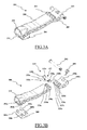
- Figures 2A and 2B show a perspective view a fluff filter assembly (which in the following, for simplicity, will be called also "fluff filter”) 200 , comprising, in this particular example, a filter frame 200a , and one or more fluff filtering surfaces 200b (comprising for example a suitable net, or a sieve, or any kind of septum adapted to allow the passage of air but to impede the passage of lint or fluff); clearly the fluff filter 200 can be of any other type.
- Figure 2A is a front view
- Figure 2B is a rear view, respectively, of a fluff filter 200 according to the invention.
- the fluff filter 200 advantageously comprises an upper face 140 preferably, but not necessarily, substantially flat, comprising a grid structure 205 that prevents clothes or foreign matters from accessing the fluff filter 200 itself and the drying air circuit downstream the fluff filter 200.
- a seat 210 is provided preferably, but not necessarily, in the middle of the upper face 140 for receiving a fluff filter revealing device according to an embodiment of the present invention (not shown in Figures 2A and 2B ).
- the seat 210 further comprises first blocking means 215, for example a recess 215 , whose purpose will be explained in the following.
- the fluff filter 200 comprises releasable filter blocking means, adapted for releasably blocking the fluff filter 200 to the fluff filter seat inside the cabinet 105 ; these filter releasable blocking means comprise, for example, a resilient hook 220 projecting from beneath upper surface 140 rim toward the bottom of the fluff filter 200 , adapted to releasably blocking said fluff filter 200 to the fluff filter seat inside the cabinet 105 , as will result more clear in the following.
- Figures 3A and 3B show a fluff filter revealing device according to an embodiment of the present invention; in particular Figure 3A shows the fluff filter revealing device fully assembled, while Figure 3B shows an exploded view of the revealing device.
- the fluff filter revealing device comprises a door abutment portion with an associated biasing element configured for biasing the door abutment portion towards a position protruding externally from the cabinet in proximity of the loading opening.
- the fluff filter revealing device advantageously comprises a sort of lever comprising two portions: a first portion 305, preferably arc-shaped, and second portion 310, preferably substantially rectilinear and longer than the first portion.
- first portion 305 preferably arc-shaped
- second portion 310 preferably substantially rectilinear and longer than the first portion.
- the above mentioned abutment portion comprises the second portion 310 .
- the two portions 305 and 310 are hinged together, preferably, but not necessarily, by a hinge 315 .
- Said hinge 315 comprises in particular three appendages 320a , 320b and 320c , each provided with an eye, in comb-like arrangement on a first end of the second portion 310 .
- first end of the first portion 305 there are arranged, also comb-like, four appendages 325a , 325b , 325c and 325d each provided with an eye; the eyes of the appendages 325a , 325b , 325c has substantially the same diameter as the eyes of the appendages 320a , 320b and 320c , while the eye of the appendage 325d has a smaller diameter compared to the others.
- the appendages 320a , 320b , 320c , 325a , 325b , 325c and 325d are arranged on the ends of the respective device portions in such a way as, when the second and first device portions are assembled, the appendages 320a , 320b , 320c and the appendages 325a , 325b, 325c, 325d are interleaved, and the appendages eyes are aligned, so that a pivot 327 , comprising two parts 330a and 330b , can be inserted for obtaining a pin hinge.
- the pivot part 330a comprises a hollow cylindrical body 335a , insertable into the eyes of the appendages 320a , 320b , 320c , 325a , 325b , 325c , with a circular, enlarged head 335b ;
- the pivot part 330b comprises a cylindrical body 340a , having a diameter smaller than the diameter of the hollow cylindrical body 335a and essentially matching the diameter of the eye of the appendage 325d , so as to result insertable thereinto and into the hollow cylindrical body 335a , and a circular enlarged head 340b .
- the flat circular heads 335b and 340b prevent the pivot 327 from sliding out of the appendages eyes.
- hinge 315 is only an example, and it can be replaced by any suitable hinge adapted to connect in a rotatable way the first portion 305 and the second portion 310 .
- the first and second portions of the fluff filter revealing device 300 are obtained in a single piece construction, for example by moulding of a plastic material, and they can be rotated one with respect to the other for example thanks to the intrinsic elasticity of the material of which they are made, and/or thanks to a suitable shaping of the region which connects the first and second portions.
- the revealing device 300 is hinged to the annular border rim 145 of the loading opening 120 by a hinge, denoted 345, comprising for example two eyed appendages 350a, 350b provided at the second end of the first portion 305, matching corresponding eyed appendages formed on the rim of the loading opening, and a pin 360.
- a hinge denoted 345
- substantially any kind of hinge can be used for connecting the first portion 305 to the annular border rim 145 of the loading opening.
- the biasing element configured for biasing the door abutment portion (in this case the second portion 310 ) towards a position protruding externally from the cabinet in proximity of the loading opening advantageously comprises a biasing element, in the example here considered a retaining spring 355 inserted on the pin 360 in a position intermediate between the appendages 350a , 350b; the spring 355 is adapted to bias the filter revealing device 300 towards an open position illustrated for example in Figures 4B and 4C (in which at least a part of the filter revealing device 300 protrudes from the annular border rim 145 of the loading opening 120 so as to prevent the door from closing), once the user manually releases the filter revealing device 300 from the respective seat 210 formed in the fluff filter frame at the top thereof.
- a biasing element in the example here considered a retaining spring 355 inserted on the pin 360 in a position intermediate between the appendages 350a , 350b; the spring 355 is adapted to bias the filter revealing device 300 towards an open position illustrated for example
- a cushion 380 (or similar damping means) is provided at the second 310 end opposite to the first end thereof, for preventing scuffs on the door 130 internal face should the latter come into contact with the filter revealing device 300 due for example to an attempt of closing the door without the filter in the working position.
- the cushion 380 is mounted to the second portion 310 for example by snap-fit through projections 385a , 385b , 385c and 385d shaped to enable snap-fit engagement with four respective apertures (only two 390a and 390b shown in Figure 3B ) formed in the long strip-like portion 310.
- cushion 380 may be associated to the fluff filter revealing device 300 by any other suitable fixing means, for example by glueing, and/or by welding, and/or by overmoulding.
- the second portion 310 is provided, at the second end thereof, with second blocking means, for the reciprocal cooperation with the first blocking means, and in particular, as in the considered example, adapted to engage the first blocking means 215 provided in the filter 200 frame, so as to releasably block the filter revealing device 300 to the fluff filter 200 in a locked position, illustrated for example in Figures 4A and 5A .
- the second blocking means can comprise a projection 370 shaped so as to match the retaining recess 215, in particular configured to snap fit into the recess 215 obtained in the seat 210 , so as to releasably block the filter revealing device 300 in a locked position.
- the second blocking means in this example the projection 370
- the first blocking means in this example the retaining recess 215
- the second portion 310 of the filter revealing device 300 further comprises, in correspondence of its second end and on a face opposite to the cushion, holding means adapted to facilitate the unlocking of the filter revealing device 300 ; advantageously the holding means comprises an appendage 375 defining a hook for a finger.
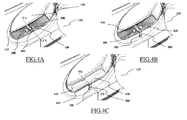
- the fluff filter 200 is in a correct working position
- the filter revealing device 300 is associated to the fluff filter 200 in a locking position in which the filter revealing device 300 is retained in the seat 210 of the fluff filter 200 by the snap-fit engagement of the projection 370 with the recess 215.
- Such a configuration of the fluff filter 200 and filter revealing device 300 could be defined as door unblocking position, since in this position it is possible to close the door 135 , i.e. the closure of the door is unblocked.
- the filter revealing device 300, the fluff filter seat 410 and the fluff filter 200 are arranged in such a way that the filter revealing device 300 can be fixed to the fluff filter 200 in the locking position only if the fluff filter 200 is inserted into the fluff filter seat 410 in the correct working position, while the filter revealing device 300 cannot be fixed to the fluff filter 200 in the locking position if the fluff filter is not inserted into the fluff filter seat 410 or it isn't in the correct working position.
- the resilient hook 220 is in turn snap-fit engaged with a recess 415 , formed in a back wall of the fluff filter seat 410 , and in this way the fluff filter 200 is firmly kept in the correct working position.
- the user When the user wishes to remove the fluff filter 200 for, e . g . cleaning or replacing it with a new filter, the user has to act on the revealing device 300 so that the latter moves from the locking position to an open position, shown in Figure 4B , as it will be better explained in the following.
- This open position corresponds to a door blocking position in which the filter revealing device 300 prevents the closure of the door 135 .
- the user simply slightly pulls upwards the revealing device 300 , using a finger to catch the hook 375 .
- the retaining spring 355 pulls backward the device 300 , until the first portion 305 has rotated by an angle of substantially 180° around the hinge 405 , and this causes the second portion 310 , under its own weight, to rotate about the hinge 315 until a rest position is reached.
- the second portion 310 In the rest position, the second portion 310 is substantially parallel and adjacent to the annular border 125 of the loading opening.
- the filter revealing device 300 In this position the filter revealing device 300 thus prevents the door closure; in this position the cushion 380 faces outwards, so as to prevent any scuffing of the door 135 internal face should the user inadvertently try to close the door when the fluff filter 200 is not inserted or it is not in the correct working position.
- the fluff filter 200 With the revealing device 300 in this position, the fluff filter 200 can be extracted from its seat 410 , by simply pulling the fluff filter 200 up enough to cause the hook 220 to flex inward and disengage from the recess 415 .
- the revealing device 300 After the removal of the fluff filter 200 , the revealing device 300 remains in the open position, as shown in Figure 3 , still preventing the door closure.
- the filter revealing device 300 can be brought back by the user to the locking position (that is, the door unblocking position as described in the above) of Figure 4A , and the door can again be closed.
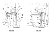
- Figure 5A is a section view of the lower side of the loading opening and front panel showing the fluff filter 200 housed in its seat 410 with the filter revealing device 300 according to an embodiment of the present invention in locking position.
- the second portion 310 and the device seat bottom 505 are shaped so as to fit each other.
- the projection 370 present at the end of the second portion 310 firmly engages the recess 215 while in locking position.
- Figure 5B is a section view of the lower side of the loading opening 120 and front panel 115 showing the fluff filter seat 410 with the filter removed, and the filter revealing device 300, according to an embodiment of the present invention, in opened position preventing the loading door 135 from closing.
- the first portion 305 of the device 300 is rotated by approximately 180° in the open position, while the second portion 310 is substantially parallel and adjacent to the annular border 125 , abutting the same by its hook-like appendage 375 .
- the spring 355 of the hinge 405 biases the device 300 to maintain the open position, until the user correctly reinstalls the fluff filter 200 into its seat 410 and pulls the device 300 until the projection 370 engages the recess 215, reaching the locking position (as shown earlier in Figure 4A ).
- the device 300 in open position prevents the door 135 from completely closing the loading opening 120 . It is possible to notice that the filter revealing device 300 contacts the door 135 only by the cushion 380 , ensuring that the door 135 is not damaged while contacting the device 300, even if pushed strongly against the cushion 380 .
- the presence of the cushion 380 is only a preferable feature, but it is not necessary for the functioning of the present invention; in a further embodiment the cushion is not provided and the filter revealing device 300 contacts the door 135 directly.
- the fluff filter revealing device 300 comprises a single flexible portion, a first end of which is rotatably associated with the annular border rim 145 of the loading opening 120 and cooperates with biasing means, for example, a retaining spring, adapted to bias the filter revealing device 300 towards an open position in which at least a part of the filter revealing device 300 protrudes from the annular border rim 145 of the loading opening 120 so as to prevent the door from closing.
- biasing means for example, a retaining spring
- the above mentioned door abutment portion comprises a second end of the single flexible portion; advantageously the second end of the single flexible portion is provided with second blocking means, adapted to engage the first blocking means 215 provided in the filter 200 frame, so as to releasably block the filter revealing device 300 to the fluff filter 200 in the locked position.
- Figure 6 shows in a perspective view, a tumble dryer with the door wide open.
- a machine front panel 600 is essentially identical to that shown in Figure 1 apart from being provided with a hole 605 in a lower left quadrant of the border 610 , preferably annular, of the loading opening.
- the fluff filter revealing device comprises a door abutment portion with an associated biasing element configured for biasing the door abutment portion towards a position protruding externally from the cabinet in proximity of the loading opening; in this case the door abutment portion comprises a pushbutton 615 slidable through the hole 605, so as to project outwardly from the hole 605 and to prevent a door 620 from closing if a fluff filter (of which is visible only its upper face 625 ) is removed from its seat or generally not in correct working position, as will be more extensively described in the following.
- the fluff filter may be identical to the one described in connection with the previous embodiment, with the only difference that in the present case the filter has not the device seat 210 in its upper face.
- FIG. 7 is a section view showing a fluff filter revealing device 700 , according to the herein described embodiment of the present invention.
- the device 700 is mounted in an internal cavity of the front panel in correspondence to the region from which the pushbutton 615 projects trough the hole 605 .
- the filter revealing device 700 comprises, in addition to the pushbutton 615 , a pushbutton blocking element for blocking the backward movement of the pushbutton 615 .
- Said pushbutton blocking element comprise for example, as shown in Figure 7 , a lever 705, preferably, but not necessarily, substantially S-shaped, a first end 710 of which is arranged so as to be automatically actuated by the fluff filter 715 (only partly shown), when the fluff filter is inserted into its seat and pushed downward.
- the lever 705 is hinged in 720 to the inner walls of the front panel 600 .
- a second end 730 of the lever 705 is arranged so as to engage the pushbutton 615 when the fluff filter 715 is removed from it seat.
- the biasing element configured for biasing the door abutment portion (in this case the pushbutton 615 ) towards a position protruding externally from the cabinet in proximity of the loading opening comprises first biasing means, for example a biasing element 810 , e.g. a coil spring, fitted, for axially biasing the pushbutton 615 outwardly from the hole 605 , in its rest position; in this embodiment the pushbutton 615 advantageously comprises a hollow cylindrical body 805 open at a rear end, inside which the coil spring 810 is fitted. The spring 810 is attached at one end thereof to the internal wall of the tumble dryer.
- a biasing element 810 e.g. a coil spring
- the fluff filter revealing device 700 comprises second biasing means 825 , for example a retaining spring, for biasing the lever 705 in locking position, in which the second end 730 of the lever engages the groove 830 .
- the free end of the pushbutton 615 can comprise a cushion (or similar damping means), not illustrated, adapted for preventing scuffs on the internal face of the door 620 should the latter come into contact with the pushbutton 615 due for example to an attempt of closing the door 620 without the fluff filter in the working position.
- a cushion or similar damping means
- the spring 825 biases the lever 705 to rotate counterclockwise, until the second end 730 of the lever engages the groove 830 of the pushbutton 615 . In this position, the lever 705 prevents axial sliding movement of the pushbutton 615 , and thus the door 620 cannot be closed until the fluff filter 715 is reinstalled correctly into its seat.
- the user is able to detect whether the fluff filter revealing device 700 operates properly, by simply checking the blocking of the pushbutton 615 once the fluff filter 715 is removed from it seat, without the need for closing the door 620 .
Landscapes
- Engineering & Computer Science (AREA)
- Textile Engineering (AREA)
- Detail Structures Of Washing Machines And Dryers (AREA)
Abstract
Description
- The present invention relates to laundry drying machines, like laundry dryers and washer/dryers, for example tumble dryers.
- In particular the invention relates to a revealing device for revealing the presence and/or the correct positioning of a fluff filter and for preventing the machine operation when the fluff filter is not properly positioned.
- As known, tumble dryers typically comprise a cabinet substantially parallepiped-shaped; the cabinet accommodates a rotatable drum apt to contain the laundry to be dried, as well as the electrical, electronic, mechanical, and hydraulic components necessary for the operation of the tumble dryer. A front panel of the cabinet has a loading opening to access the rotatable drum for loading/unloading the laundry, and a door is provided for closing the loading opening, particularly during the tumble dryer operation.
- In operation, the laundry is dried by causing warm, dry air to flow through the drum while the latter is rotated, so that the laundry is tumbled.
- During the drying process, the clothes inside the rotating drum typically loose lint particles or fluff. Said fluff is light and tiny so it can be brought by the hot air flow into the drying air circuit. Once the fluff enters the drying air circuit, it can obstruct it or affect the fan operation, to the extent of possibly cause the latter to stop; in general, this has a detrimental effect on the dryer functioning.
- Therefore, fluff (or "de-fluff") filters have been designed suitable to retain the fluff so as to prevent it from damaging the dryer's components. The fluff filter needs to be periodically cleaned to avoid it to get clogged; to this purpose, the fluff filter is removably accommodated in a filter seat, for example located at the front of the cabinet, adjacent the loading opening and in fluid communication with the drying air circulation circuit.
- The removability of the fluff filter however is intrinsically dangerous: there is in fact the possibility that a user, after removing the fluff filter for cleaning it, forgets to reinstall the filter in its seat or reinstalls it in a wrong way before setting the dryer in operation.
- Solutions have been proposed to overcome this problem.
- For example,
EP 0443361 discloses a fluff filter monitor device for laundry driers comprising a flexible plastic strip member fixedly mounted in a housing space for the filter, so that, when the filter is removed, the flexible strip member is displaced and intercepts the movement of a lug projecting from the loading opening door and therefore preventing the door from closing. - One of the major drawback of the aforementioned solution is that the monitoring device is embedded inside the filter seat, thereby it is out of the sight and unreachable by the user. Consequently a user cannot notice if the monitor device works properly or if the prolonged use has caused a reduction of its flexibility to the extent that the monitor device is no longer capable of preventing the closure of the door. Should this happen, the user could inadvertently close the door and set the machine in operation even if he/she forgot to reinstall the filter after its removal. This solution also needs a complex procedure during in-factory assembly, due to the fact that the filter seat offers a narrow workspace.
- The purpose of the present invention is to provide a device suitable for revealing the absence of the fluff filter from its working position that at least partly overcomes said drawbacks.
- It is underlined that in the present application the expression "working position" (or "correct working position") of the fluff filter has to be intended as a position of the fluff filter with respect to its seat which ensures that lint or fluff can't go into the drying air circulation circuit downstream the fluff filter; in other words the fluff filter is considered in the working position if it is correctly inserted in its seat, while the fluff filter is not in the working position if it is not inserted in the seat or if it is inserted in the seat in a wrong or non-perfect way, so that some fluff can avoid the fluff filter and enter into the circulation circuit downstream the fluff filter.
- Essentially, according to the present invention, a device is proposed for revealing that the fluff filter is not inserted into the respective housing/seat, or generally it is not in the correct working position. The revealing device is structured and arranged in such a way as to at least partly protruding outside the loading opening of the appliance when the fluff filter is out of its seat or generally not properly positioned thereinto. In this way, by protruding out of the loading opening, the revealing device is adapted to prevent the loading door from closing in case the fluff filter is not in working position, and moreover it is visible to the user, the latter can realize of any possible breakage or malfunctioning thereof.
- The solution according to the present invention is more reliable in ensuring that the machine operation is prevented in case the fluff filter is not properly installed, or in general when it is not in working position, is less prone to failures, and needs a cheaper and a simpler assembly process during manufacturing.
- One aspect of the present invention relates to a laundry drying machine comprising an external cabinet, which contains a rotatable drum for laundry to be dried and a loading opening for allowing laundry loading into and unloading from the drum; a door is provided for closing said loading opening. The laundry drying machine further comprises a drying air circuit for circulating drying air for drying the laundry, where a removable fluff filter adapted to be associated with said drying air circuit in a working position in which said fluff filter retains fluff suspended in the drying air, so as to avoid that fluff goes into said drying air circuit downstream said fluff filter. Said removable fluff filter is secured by a filter revealing device configured for automatically preventing the door from being closed when the filter is not in said working position. Said filter revealing device is characterized in that it is arranged to at least partly protrude externally from said cabinet in proximity of the loading opening when the fluff filter is not in said working position.
- Preferred embodiments of the invention are set forth in the dependent claims.
- These, and others, features and advantages of the solution according to the present invention will be better understood with reference to the following detailed description of some embodiments thereof, provided for illustrative and not restrictive purposes, to be read in conjunction with the attached drawings. In this regard, it is expressly intended that the drawings are not necessarily to scale and that, unless specified otherwise, they simply aim to conceptually illustrate the structures and procedures. In particular:
-
Figure 1 shows in a perspective view, a tumble drier provided with a filter revealing device according to an embodiment of the present invention, with the door wide open; -
Figure 2A shows a first perspective view of a fluff filter; -
Figure 2B shows a second perspective view of the fluff filter; -
Figure 3A shows a perspective view of an embodiment according to the present invention of a filter revealing device for preventing the machine loading door from closing unless the fluff filter is in proper working position; -
Figure 3B shows an exploded view of the filter revealing device ofFigure 3A ; -
Figure 4A shows an enlarged perspective view of the loading opening of the machine with the fluff filter inserted into its seat in the correct working position, and of the device ofFigures 3A and 3B ; -
Figure 4B shows an enlarged perspective view of the loading opening of the machine with the fluff filter inserted in its seat, and the filter revealing device in opened position; -
Figure 4C shows a detailed perspective view of the loading opening of the machine without the fluff filter and the filter revealing device according to an embodiment of the present invention in opened position; -
Figure 5A is a sectional view, along the plane indicated VA-VA inFigure 4A , of the lower side of the loading opening and front panel showing the fluff filter housed in its seat in the correct working position and with the filter revealing device according to an embodiment of the present invention in closed position; -
Figure 5B is a sectional view, along the plane indicated VB-VB inFigure 4C , of the lower side of the loading opening and front panel showing the fluff filter seat without the fluff filter and with the filter revealing device according to an embodiment of the present invention in opened position preventing the loading door from closing; -
Figure 6 shows in a perspective view a front panel of a tumble dryer comprising a filter revealing device according to another embodiment of the present invention; -
Figure 7 is a detailed view of a filter revealing device according to the embodiment ofFigure 6 ; -
Figure 8 is an exploded view of the filter revealing device ofFigures 6 and7 ; -
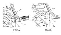
Figure 9A is a cutaway view of a machine with the filter revealing device ofFigures 6 and7 , in a free position; and -
Figure 9B is a cutaway view similar to that ofFigures 9A , with the filter revealing device ofFigures 6 and7 in locking position; - With reference to
Figure 1 , there is shown in a perspective view, a tumble drier with the laundry loading door wide open. - The tumble dryer, denoted as 100 in the drawings, comprises a
cabinet 105, for example parallepiped-shaped. The cabinet accommodates arotatable drum 110 apt to contain the laundry to be dried, as well as the electrical, electronic, mechanical, and hydraulic components necessary for the operation of the tumble dryer (not shown in Figures since they are well known in the art). Afront panel 115 of the cabinet has aloading opening 120 to access therotatable drum 110 for loading/unloading the laundry to be dried. Theloading opening 120 has aborder 125, preferably substantially annular, in which door hinges 130 as well as door locking means (not shown) are arranged for, respectively, hinging and locking adoor 135. Saiddoor 135 is adapted for sealably closing said loading opening 120 during the tumble dryer operation. A fluff filter (whose upper side is visible inFigure 1 , and denoted therein as 140) is housed in a fluff filter seat (numbered 410 inFigures 5A and 5B and not shown inFigure 1 ) formed in correspondence of thefront panel 115 adjacent to theloading opening 120 and behind theannular border 125. The fluff filterupper side 140 is, in this particular embodiment, substantially flat, and more in general it is capable of adapting itself to aperipheral rim 145 of theannular border 125, once correctly housed in its seat. -
Figures 2A and 2B show a perspective view a fluff filter assembly (which in the following, for simplicity, will be called also "fluff filter") 200, comprising, in this particular example, afilter frame 200a, and one or morefluff filtering surfaces 200b (comprising for example a suitable net, or a sieve, or any kind of septum adapted to allow the passage of air but to impede the passage of lint or fluff); clearly thefluff filter 200 can be of any other type. In particular,Figure 2A is a front view, whileFigure 2B is a rear view, respectively, of afluff filter 200 according to the invention. Thefluff filter 200 advantageously comprises anupper face 140 preferably, but not necessarily, substantially flat, comprising agrid structure 205 that prevents clothes or foreign matters from accessing thefluff filter 200 itself and the drying air circuit downstream thefluff filter 200. Aseat 210 is provided preferably, but not necessarily, in the middle of theupper face 140 for receiving a fluff filter revealing device according to an embodiment of the present invention (not shown inFigures 2A and 2B ). Theseat 210 further comprises first blocking means 215, for example arecess 215, whose purpose will be explained in the following. - Advantageously, the
fluff filter 200 comprises releasable filter blocking means, adapted for releasably blocking thefluff filter 200 to the fluff filter seat inside thecabinet 105; these filter releasable blocking means comprise, for example, aresilient hook 220 projecting from beneathupper surface 140 rim toward the bottom of thefluff filter 200, adapted to releasably blocking saidfluff filter 200 to the fluff filter seat inside thecabinet 105, as will result more clear in the following. -
Figures 3A and 3B show a fluff filter revealing device according to an embodiment of the present invention; in particularFigure 3A shows the fluff filter revealing device fully assembled, whileFigure 3B shows an exploded view of the revealing device. - Advantageously, as will be better explained in the following, the fluff filter revealing device comprises a door abutment portion with an associated biasing element configured for biasing the door abutment portion towards a position protruding externally from the cabinet in proximity of the loading opening.
- In the embodiments illustrated in
Figures 3A and 3B , the fluff filter revealing device, globally denoted 300, advantageously comprises a sort of lever comprising two portions: afirst portion 305, preferably arc-shaped, andsecond portion 310, preferably substantially rectilinear and longer than the first portion. As will be better explained in the following, in this embodiment the above mentioned abutment portion comprises thesecond portion 310. - The two
portions hinge 315. Saidhinge 315 comprises in particular threeappendages second portion 310. On a facing, first end of thefirst portion 305 there are arranged, also comb-like, fourappendages appendages appendages appendage 325d has a smaller diameter compared to the others. Advantageously, theappendages appendages appendages pivot 327, comprising twoparts pivot part 330a comprises a hollowcylindrical body 335a, insertable into the eyes of theappendages enlarged head 335b; thepivot part 330b comprises acylindrical body 340a, having a diameter smaller than the diameter of the hollowcylindrical body 335a and essentially matching the diameter of the eye of theappendage 325d, so as to result insertable thereinto and into the hollowcylindrical body 335a, and a circularenlarged head 340b. The flatcircular heads pivot 327 from sliding out of the appendages eyes. - Clearly the above described
hinge 315 is only an example, and it can be replaced by any suitable hinge adapted to connect in a rotatable way thefirst portion 305 and thesecond portion 310. - In another embodiment, not illustrated, the first and second portions of the fluff
filter revealing device 300 are obtained in a single piece construction, for example by moulding of a plastic material, and they can be rotated one with respect to the other for example thanks to the intrinsic elasticity of the material of which they are made, and/or thanks to a suitable shaping of the region which connects the first and second portions. - In correspondence of a second end of the
first portion 305, the revealingdevice 300 is hinged to theannular border rim 145 of theloading opening 120 by a hinge, denoted 345, comprising for example twoeyed appendages first portion 305, matching corresponding eyed appendages formed on the rim of the loading opening, and apin 360. Clearly, also in this case substantially any kind of hinge can be used for connecting thefirst portion 305 to theannular border rim 145 of the loading opening. - In this embodiment the biasing element configured for biasing the door abutment portion (in this case the second portion 310) towards a position protruding externally from the cabinet in proximity of the loading opening advantageously comprises a biasing element, in the example here considered a retaining
spring 355 inserted on thepin 360 in a position intermediate between theappendages spring 355 is adapted to bias thefilter revealing device 300 towards an open position illustrated for example inFigures 4B and 4C (in which at least a part of thefilter revealing device 300 protrudes from theannular border rim 145 of theloading opening 120 so as to prevent the door from closing), once the user manually releases thefilter revealing device 300 from therespective seat 210 formed in the fluff filter frame at the top thereof. - A cushion 380 (or similar damping means) is provided at the second 310 end opposite to the first end thereof, for preventing scuffs on the
door 130 internal face should the latter come into contact with thefilter revealing device 300 due for example to an attempt of closing the door without the filter in the working position. Thecushion 380 is mounted to thesecond portion 310 for example by snap-fit through projections 385a, 385b, 385c and 385d shaped to enable snap-fit engagement with four respective apertures (only two 390a and 390b shown inFigure 3B ) formed in the long strip-like portion 310. - Clearly the
cushion 380 may be associated to the flufffilter revealing device 300 by any other suitable fixing means, for example by glueing, and/or by welding, and/or by overmoulding. - Furthermore, the
second portion 310 is provided, at the second end thereof, with second blocking means, for the reciprocal cooperation with the first blocking means, and in particular, as in the considered example, adapted to engage the first blocking means 215 provided in thefilter 200 frame, so as to releasably block thefilter revealing device 300 to thefluff filter 200 in a locked position, illustrated for example inFigures 4A and5A . - For example the second blocking means can comprise a
projection 370 shaped so as to match the retainingrecess 215, in particular configured to snap fit into therecess 215 obtained in theseat 210, so as to releasably block thefilter revealing device 300 in a locked position. - Clearly the second blocking means (in this example the projection 370) can be provided on either the fluff filter revealing device or the fluff filter, and the first blocking means (in this example the retaining recess 215) can be accordingly provided on either the fluff filter or the fluff filter revealing device.
- The
second portion 310 of thefilter revealing device 300 further comprises, in correspondence of its second end and on a face opposite to the cushion, holding means adapted to facilitate the unlocking of thefilter revealing device 300; advantageously the holding means comprises anappendage 375 defining a hook for a finger. - The operation of the
filter revealing device 300 will be now described, with the aid ofFigures 4A, 4B and 4C , which show a close up perspective view of theloading opening 120. - In particular, referring to
Figure 4A thefluff filter 200 is in a correct working position, and thefilter revealing device 300 is associated to thefluff filter 200 in a locking position in which thefilter revealing device 300 is retained in theseat 210 of thefluff filter 200 by the snap-fit engagement of theprojection 370 with therecess 215. Such a configuration of thefluff filter 200 andfilter revealing device 300 could be defined as door unblocking position, since in this position it is possible to close thedoor 135, i.e. the closure of the door is unblocked. Thefilter revealing device 300, thefluff filter seat 410 and thefluff filter 200 are arranged in such a way that thefilter revealing device 300 can be fixed to thefluff filter 200 in the locking position only if thefluff filter 200 is inserted into thefluff filter seat 410 in the correct working position, while thefilter revealing device 300 cannot be fixed to thefluff filter 200 in the locking position if the fluff filter is not inserted into thefluff filter seat 410 or it isn't in the correct working position. Advantageously, when thefluff filter 200 is in the working position, theresilient hook 220 is in turn snap-fit engaged with arecess 415, formed in a back wall of thefluff filter seat 410, and in this way thefluff filter 200 is firmly kept in the correct working position. - When the user wishes to remove the
fluff filter 200 for, e.g. cleaning or replacing it with a new filter, the user has to act on the revealingdevice 300 so that the latter moves from the locking position to an open position, shown inFigure 4B , as it will be better explained in the following. This open position corresponds to a door blocking position in which thefilter revealing device 300 prevents the closure of thedoor 135. To do this, the user simply slightly pulls upwards the revealingdevice 300, using a finger to catch thehook 375. As soon as theprojection 370 disengages therecess 215, the retainingspring 355 pulls backward thedevice 300, until thefirst portion 305 has rotated by an angle of substantially 180° around thehinge 405, and this causes thesecond portion 310, under its own weight, to rotate about thehinge 315 until a rest position is reached. In the rest position, thesecond portion 310 is substantially parallel and adjacent to theannular border 125 of the loading opening. In this position thefilter revealing device 300 thus prevents the door closure; in this position thecushion 380 faces outwards, so as to prevent any scuffing of thedoor 135 internal face should the user inadvertently try to close the door when thefluff filter 200 is not inserted or it is not in the correct working position. With the revealingdevice 300 in this position, thefluff filter 200 can be extracted from itsseat 410, by simply pulling thefluff filter 200 up enough to cause thehook 220 to flex inward and disengage from therecess 415. - After the removal of the
fluff filter 200, the revealingdevice 300 remains in the open position, as shown inFigure 3 , still preventing the door closure. - When the fluff filter is reinserted into the seat, and it is placed in the correct working position, the
filter revealing device 300 can be brought back by the user to the locking position (that is, the door unblocking position as described in the above) ofFigure 4A , and the door can again be closed. -
Figure 5A is a section view of the lower side of the loading opening and front panel showing thefluff filter 200 housed in itsseat 410 with thefilter revealing device 300 according to an embodiment of the present invention in locking position. Thesecond portion 310 and thedevice seat bottom 505 are shaped so as to fit each other. Theprojection 370 present at the end of thesecond portion 310 firmly engages therecess 215 while in locking position. -
Figure 5B is a section view of the lower side of theloading opening 120 andfront panel 115 showing thefluff filter seat 410 with the filter removed, and thefilter revealing device 300, according to an embodiment of the present invention, in opened position preventing theloading door 135 from closing. As stated above thefirst portion 305 of thedevice 300 is rotated by approximately 180° in the open position, while thesecond portion 310 is substantially parallel and adjacent to theannular border 125, abutting the same by its hook-like appendage 375. Thespring 355 of thehinge 405 biases thedevice 300 to maintain the open position, until the user correctly reinstalls thefluff filter 200 into itsseat 410 and pulls thedevice 300 until theprojection 370 engages therecess 215, reaching the locking position (as shown earlier inFigure 4A ). - The
device 300 in open position prevents thedoor 135 from completely closing theloading opening 120. It is possible to notice that thefilter revealing device 300 contacts thedoor 135 only by thecushion 380, ensuring that thedoor 135 is not damaged while contacting thedevice 300, even if pushed strongly against thecushion 380. However the presence of thecushion 380 is only a preferable feature, but it is not necessary for the functioning of the present invention; in a further embodiment the cushion is not provided and thefilter revealing device 300 contacts thedoor 135 directly. - In a further embodiment, not illustrated, the fluff
filter revealing device 300 comprises a single flexible portion, a first end of which is rotatably associated with theannular border rim 145 of theloading opening 120 and cooperates with biasing means, for example, a retaining spring, adapted to bias thefilter revealing device 300 towards an open position in which at least a part of thefilter revealing device 300 protrudes from theannular border rim 145 of theloading opening 120 so as to prevent the door from closing. In this case the above mentioned door abutment portion comprises a second end of the single flexible portion; advantageously the second end of the single flexible portion is provided with second blocking means, adapted to engage the first blocking means 215 provided in thefilter 200 frame, so as to releasably block thefilter revealing device 300 to thefluff filter 200 in the locked position. - Another embodiment of the present solution is shown in
Figures 6 - 9 . In particular,Figure 6 shows in a perspective view, a tumble dryer with the door wide open. Amachine front panel 600 is essentially identical to that shown inFigure 1 apart from being provided with ahole 605 in a lower left quadrant of theborder 610, preferably annular, of the loading opening. - As will be better explained in the following, also in this embodiment the fluff filter revealing device comprises a door abutment portion with an associated biasing element configured for biasing the door abutment portion towards a position protruding externally from the cabinet in proximity of the loading opening; in this case the door abutment portion comprises a
pushbutton 615 slidable through thehole 605, so as to project outwardly from thehole 605 and to prevent adoor 620 from closing if a fluff filter (of which is visible only its upper face 625) is removed from its seat or generally not in correct working position, as will be more extensively described in the following. - The fluff filter may be identical to the one described in connection with the previous embodiment, with the only difference that in the present case the filter has not the
device seat 210 in its upper face. -
Figure 7 is a section view showing a flufffilter revealing device 700, according to the herein described embodiment of the present invention. Thedevice 700 is mounted in an internal cavity of the front panel in correspondence to the region from which thepushbutton 615 projects trough thehole 605. Thefilter revealing device 700 comprises, in addition to thepushbutton 615, a pushbutton blocking element for blocking the backward movement of thepushbutton 615. Said pushbutton blocking element comprise for example, as shown inFigure 7 , alever 705, preferably, but not necessarily, substantially S-shaped, afirst end 710 of which is arranged so as to be automatically actuated by the fluff filter 715 (only partly shown), when the fluff filter is inserted into its seat and pushed downward. Thelever 705 is hinged in 720 to the inner walls of thefront panel 600. Asecond end 730 of thelever 705 is arranged so as to engage thepushbutton 615 when thefluff filter 715 is removed from it seat. - Advantageously in the embodiment of
Figure 8 the biasing element configured for biasing the door abutment portion (in this case the pushbutton 615) towards a position protruding externally from the cabinet in proximity of the loading opening comprises first biasing means, for example a biasingelement 810, e.g. a coil spring, fitted, for axially biasing thepushbutton 615 outwardly from thehole 605, in its rest position; in this embodiment thepushbutton 615 advantageously comprises a hollowcylindrical body 805 open at a rear end, inside which thecoil spring 810 is fitted. Thespring 810 is attached at one end thereof to the internal wall of the tumble dryer. Two annular projections 815a and 815b are provided on the first hollowcylindrical body 805, adapted to prevent thepushbutton 615 from being expelled from thehole 605, and at the same to define a groove 830 that forms a catch for the engagement by thesecond end 730 of thelever 705 when the latter is brought in the locking position. The flufffilter revealing device 700 comprises second biasing means 825, for example a retaining spring, for biasing thelever 705 in locking position, in which thesecond end 730 of the lever engages the groove 830. - Advantageously the free end of the
pushbutton 615 can comprise a cushion (or similar damping means), not illustrated, adapted for preventing scuffs on the internal face of thedoor 620 should the latter come into contact with thepushbutton 615 due for example to an attempt of closing thedoor 620 without the fluff filter in the working position. The operation of thefilter revealing device 700 according to the present embodiment of the invention is depicted in the cutaway views ofFigures 9A and 9B . - When the
fluff filter 715 is placed in its seat, thefirst end 710 of thelever 705 is pushed downward by thesame fluff filter 715, against the biasing action of thespring 825. This causes thelever 705 to slightly rotate (clockwise with reference to the enclosed drawings) about thehinge 720 axis, to an extent sufficient for causing thesecond end 730 of thelever 705 disengage the groove 830. In this way, thepushbutton 615 is left free to slide axially. When the user closes thedoor 620, the latter pushes thepushbutton 615 backward (against the action of the coil spring 810), and the door can close theloading opening 630. - Otherwise, when the
fluff filter 715 is removed from its seat, or more generally if thefluff filter 715 is not in the working position, thespring 825 biases thelever 705 to rotate counterclockwise, until thesecond end 730 of the lever engages the groove 830 of thepushbutton 615. In this position, thelever 705 prevents axial sliding movement of thepushbutton 615, and thus thedoor 620 cannot be closed until thefluff filter 715 is reinstalled correctly into its seat. - Also in this embodiment of present invention, the user is able to detect whether the fluff
filter revealing device 700 operates properly, by simply checking the blocking of thepushbutton 615 once thefluff filter 715 is removed from it seat, without the need for closing thedoor 620.
Claims (13)
- A laundry drying machine (100) comprising:- an external cabinet (105), which contains a rotatable drum (110) for laundry to be dried,- a loading opening (120; 630) for allowing laundry loading into and unloading from the drum,- a door (135; 620) for closing, said loading opening,- a drying air circuit for circulating drying air for drying the laundry,- a removable fluff filter (200; 715) adapted to be associated with said drying air circuit in a working position in which said fluff filter (200; 715) retains fluff suspended in the drying air, so as to avoid that fluff goes into said drying air circuit downstream said fluff filter (200; 715),- a filter revealing device (300; 700) configured for automatically preventing the door from being closed when the filter is not in said working position,
characterized in that
said filter revealing device (300; 700) is arranged to at least partly protrude externally from said cabinet (105) in proximity of the loading opening (120; 630) when the fluff filter (200; 715) is not in said working position. - The laundry drying machine according to claim 1, wherein said filter revealing device is arranged at least partially on a border (125; 610) of the loading opening (120; 630).
- The laundry drying machine according to claim 1 or 2, wherein said fluff filter revealing device comprises a door abutment portion (310; 615) with an associated biasing element (355; 810) configured for biasing the door abutment portion towards a position protruding externally from the cabinet in proximity of the loading opening.
- The laundry drying machine according to claim 3, wherein said door abutment portion is part of a lever hinged at a hinge (345) to the annular border of the loading opening.
- The laundry drying machine according to claim 4, wherein said biasing element is provided at said hinge (345).
- The laundry drying machine of claim 4 or 5, wherein the lever is manually actuatable for bringing it to a door unblocking position against the action of said biasing element.
- The laundry drying machine of one or more of claims 4, 5, or 6, wherein said lever and said fluff filter comprise first and second blocking means (370, 215) adapted to reciprocally cooperate for retaining the lever in the door unblocking position when the fluff filter is in the working position.
- The laundry drying machine of claim 7, wherein said first and second blocking means comprise a projection (370) provided on either the lever or the fluff filter, and a matching retaining recess (215) provided on either the fluff filter or the lever.
- The laundry drying machine according to claim 3, wherein said door abutment portion comprises a pushbutton (615) slidable through a hole (605) formed in a panel of the cabinet in proximity of the loading opening, said biasing element (810) biasing the pushbutton (615) to protrude from the hole (605).
- The laundry drying machine according to claim 9, wherein said biasing element comprises a spring axially biasing the pushbutton (615) to protrude from the hole (605).
- The laundry drying machine according to claim 9 or 10, wherein the revealing device further comprises a pushbutton blocking element (705) biased for engaging the pushbutton so as to prevent it from sliding inward through the hole when the fluff filter is not in said working position.
- The laundry drying machine according to claim 11, wherein the pushbutton blocking element (705) is arranged to be automatically actuated by the fluff filter when the latter is in said working position, so as to free the pushbutton sliding movement.
- The laundry drying machine according to any one of claims 3 to 10, wherein said door abutment portion comprises a cushion element adapted to prevent damages to the door when the latter abuts the door abutment portion.
Priority Applications (1)
| Application Number | Priority Date | Filing Date | Title |
|---|---|---|---|
| EP10156206A EP2365122B1 (en) | 2010-03-11 | 2010-03-11 | A laundry drying machine with a fluff filter revealing device |
Applications Claiming Priority (1)
| Application Number | Priority Date | Filing Date | Title |
|---|---|---|---|
| EP10156206A EP2365122B1 (en) | 2010-03-11 | 2010-03-11 | A laundry drying machine with a fluff filter revealing device |
Publications (2)
| Publication Number | Publication Date |
|---|---|
| EP2365122A1 true EP2365122A1 (en) | 2011-09-14 |
| EP2365122B1 EP2365122B1 (en) | 2012-10-31 |
Family
ID=42286705
Family Applications (1)
| Application Number | Title | Priority Date | Filing Date |
|---|---|---|---|
| EP10156206A Active EP2365122B1 (en) | 2010-03-11 | 2010-03-11 | A laundry drying machine with a fluff filter revealing device |
Country Status (1)
| Country | Link |
|---|---|
| EP (1) | EP2365122B1 (en) |
Cited By (9)
| Publication number | Priority date | Publication date | Assignee | Title |
|---|---|---|---|---|
| WO2013085349A1 (en) * | 2011-12-08 | 2013-06-13 | Lg Electronics Inc. | Filter guide having latch device of filter cover and clothes-drying machine using the same |
| WO2014024393A1 (en) | 2012-08-08 | 2014-02-13 | パナソニック株式会社 | Clothes dryer |
| EP2787116A1 (en) * | 2013-04-03 | 2014-10-08 | Electrolux Appliances Aktiebolag | Tumble dryer |
| WO2015024757A1 (en) * | 2013-08-23 | 2015-02-26 | BSH Bosch und Siemens Hausgeräte GmbH | Laundry treatment apparatus comprising a receiving device |
| EP2860305A3 (en) * | 2013-10-02 | 2015-08-19 | Miele & Cie. KG | Tumble dryer |
| EP2933370A1 (en) * | 2014-04-15 | 2015-10-21 | Miele & Cie. KG | Tumble dryer |
| EP2975173A1 (en) * | 2014-07-18 | 2016-01-20 | LG Electronics Inc. | Clothes treating apparatus |
| CN107988772A (en) * | 2017-11-24 | 2018-05-04 | 青岛海尔洗衣机有限公司 | A kind of washing-drying integral machine |
| CN111235843A (en) * | 2018-11-27 | 2020-06-05 | 青岛海尔滚筒洗衣机有限公司 | Clothes dryer |
Citations (4)
| Publication number | Priority date | Publication date | Assignee | Title |
|---|---|---|---|---|
| EP0250789A1 (en) * | 1986-07-04 | 1988-01-07 | Zanker GmbH | Laundry dryer |
| EP0443361A1 (en) | 1990-02-20 | 1991-08-28 | INDUSTRIE ZANUSSI S.p.A. | Fluff filter monitoring device for laundry driers |
| GB2318408A (en) * | 1996-10-19 | 1998-04-22 | Aeg Hausgeraete Gmbh | Fluff filter device for an electric laundry drier |
| EP2055825A1 (en) * | 2007-10-30 | 2009-05-06 | FagorBrandt SAS | Laundry drying machine comprising a lint filter |
-
2010
- 2010-03-11 EP EP10156206A patent/EP2365122B1/en active Active
Patent Citations (4)
| Publication number | Priority date | Publication date | Assignee | Title |
|---|---|---|---|---|
| EP0250789A1 (en) * | 1986-07-04 | 1988-01-07 | Zanker GmbH | Laundry dryer |
| EP0443361A1 (en) | 1990-02-20 | 1991-08-28 | INDUSTRIE ZANUSSI S.p.A. | Fluff filter monitoring device for laundry driers |
| GB2318408A (en) * | 1996-10-19 | 1998-04-22 | Aeg Hausgeraete Gmbh | Fluff filter device for an electric laundry drier |
| EP2055825A1 (en) * | 2007-10-30 | 2009-05-06 | FagorBrandt SAS | Laundry drying machine comprising a lint filter |
Cited By (23)
| Publication number | Priority date | Publication date | Assignee | Title |
|---|---|---|---|---|
| US9285165B2 (en) | 2011-12-08 | 2016-03-15 | Lg Electronics Inc. | Method for controlling dryer |
| CN103348057A (en) * | 2011-12-08 | 2013-10-09 | Lg电子株式会社 | Filter guide having latch device of filter cover and clothes-drying machine using the same |
| WO2013085349A1 (en) * | 2011-12-08 | 2013-06-13 | Lg Electronics Inc. | Filter guide having latch device of filter cover and clothes-drying machine using the same |
| US9052142B2 (en) | 2011-12-08 | 2015-06-09 | Lg Electronics Inc. | Cabinet drum dryer filter brush |
| EP2788539A4 (en) * | 2011-12-08 | 2015-08-05 | Lg Electronics Inc | Filter guide having latch device of filter cover and clothes-drying machine using the same |
| CN103348057B (en) * | 2011-12-08 | 2016-06-22 | Lg电子株式会社 | There is the filter guide of the locking devicen for strainer cover and use the dryer of this filter guide |
| WO2014024393A1 (en) | 2012-08-08 | 2014-02-13 | パナソニック株式会社 | Clothes dryer |
| EP2787116A1 (en) * | 2013-04-03 | 2014-10-08 | Electrolux Appliances Aktiebolag | Tumble dryer |
| WO2014161813A1 (en) * | 2013-04-03 | 2014-10-09 | Electrolux Appliances Aktiebolag | Tumble dryer |
| US9567704B2 (en) | 2013-04-03 | 2017-02-14 | Electrolux Appliances Aktiebolag | Tumble dryer |
| WO2015024757A1 (en) * | 2013-08-23 | 2015-02-26 | BSH Bosch und Siemens Hausgeräte GmbH | Laundry treatment apparatus comprising a receiving device |
| CN105473780A (en) * | 2013-08-23 | 2016-04-06 | Bsh家用电器有限公司 | Laundry treatment apparatus comprising a receiving device |
| CN105473780B (en) * | 2013-08-23 | 2017-08-04 | Bsh家用电器有限公司 | Laundry treatment appliance including reception device |
| RU2630445C1 (en) * | 2013-08-23 | 2017-09-07 | Бсх Хаусгерете Гмбх | Laundry treating device with receiving device |
| US10053813B2 (en) | 2013-08-23 | 2018-08-21 | BSH Hausgeräte GmbH | Laundry treatment apparatus comprising a receiving device |
| EP2860305A3 (en) * | 2013-10-02 | 2015-08-19 | Miele & Cie. KG | Tumble dryer |
| EP2933370A1 (en) * | 2014-04-15 | 2015-10-21 | Miele & Cie. KG | Tumble dryer |
| KR20160010091A (en) * | 2014-07-18 | 2016-01-27 | 엘지전자 주식회사 | Laundry Treating Apparatus |
| CN105297331A (en) * | 2014-07-18 | 2016-02-03 | Lg电子株式会社 | Clothes treating apparatus |
| EP2975173A1 (en) * | 2014-07-18 | 2016-01-20 | LG Electronics Inc. | Clothes treating apparatus |
| CN107988772A (en) * | 2017-11-24 | 2018-05-04 | 青岛海尔洗衣机有限公司 | A kind of washing-drying integral machine |
| CN107988772B (en) * | 2017-11-24 | 2022-05-06 | 青岛海尔洗衣机有限公司 | Washing and drying integrated machine |
| CN111235843A (en) * | 2018-11-27 | 2020-06-05 | 青岛海尔滚筒洗衣机有限公司 | Clothes dryer |
Also Published As
| Publication number | Publication date |
|---|---|
| EP2365122B1 (en) | 2012-10-31 |
Similar Documents
| Publication | Publication Date | Title |
|---|---|---|
| EP2365122B1 (en) | A laundry drying machine with a fluff filter revealing device | |
| RU2534874C1 (en) | Device for laundry processing | |
| RU2294995C2 (en) | Locking unit and drying machine equipped with the same | |
| US7367134B2 (en) | Dishwasher vent assembly | |
| TWI601866B (en) | Drum washing and drying machine | |
| AU2017221661B2 (en) | Door locking device and washing machine having same | |
| US20120007482A1 (en) | Porthole Window for Laundry Washing and/or Drying Appliance | |
| EP2689705B1 (en) | System for controlling the closing of a door of household appliance, in particular for a washing machine, such as a dishwasher | |
| RU2402652C2 (en) | Self-closing accessory for access to drainage filter of washing machine with vertical load | |
| US20130145648A1 (en) | Filter guide having latch device of filter cover and clothes-drying machine using the same | |
| US6954992B2 (en) | Dryer | |
| US7159910B2 (en) | Apparatus for opening/closing door of dryer | |
| EP2796608A2 (en) | Door assembly and clothes treatment apparatus having the same | |
| US10266985B2 (en) | Collapsible drying rack for laundry dryer | |
| JP6349069B2 (en) | Drum washing machine | |
| EP2876198B1 (en) | Washing machine with drawer assembly | |
| KR20100089380A (en) | Door locking switch and a cloth treating apparatus | |
| US20180140162A1 (en) | Retainer for use in the door latch assembly of a household appliance | |
| WO2017194090A1 (en) | Laundry dryer with an improved kick panel assembly | |
| WO2017211384A1 (en) | Laundry dryer with improved ventilation performance | |
| KR20160106265A (en) | Laundry treating apparatus | |
| EP2843102B1 (en) | Laundry treating machine comprising a cover supported by a hinge | |
| KR101282949B1 (en) | Filter unit of Laundry treatment machine | |
| EP3935246B1 (en) | Resettable door locking device for an electric household appliance, in particular a dishwasher, and electric household appliance provided therewith | |
| KR101012359B1 (en) | structure of filter case in clothes dryer |
Legal Events
| Date | Code | Title | Description |
|---|---|---|---|
| PUAI | Public reference made under article 153(3) epc to a published international application that has entered the european phase |
Free format text: ORIGINAL CODE: 0009012 |
|
| AK | Designated contracting states |
Kind code of ref document: A1 Designated state(s): AT BE BG CH CY CZ DE DK EE ES FI FR GB GR HR HU IE IS IT LI LT LU LV MC MK MT NL NO PL PT RO SE SI SK SM TR |
|
| AX | Request for extension of the european patent |
Extension state: AL BA ME RS |
|
| 17P | Request for examination filed |
Effective date: 20120312 |
|
| GRAP | Despatch of communication of intention to grant a patent |
Free format text: ORIGINAL CODE: EPIDOSNIGR1 |
|
| RIC1 | Information provided on ipc code assigned before grant |
Ipc: D06F 58/22 20060101AFI20120530BHEP |
|
| GRAS | Grant fee paid |
Free format text: ORIGINAL CODE: EPIDOSNIGR3 |
|
| GRAA | (expected) grant |
Free format text: ORIGINAL CODE: 0009210 |
|
| AK | Designated contracting states |
Kind code of ref document: B1 Designated state(s): AT BE BG CH CY CZ DE DK EE ES FI FR GB GR HR HU IE IS IT LI LT LU LV MC MK MT NL NO PL PT RO SE SI SK SM TR |
|
| REG | Reference to a national code |
Ref country code: GB Ref legal event code: FG4D Ref country code: CH Ref legal event code: EP |
|
| REG | Reference to a national code |
Ref country code: AT Ref legal event code: REF Ref document number: 582091 Country of ref document: AT Kind code of ref document: T Effective date: 20121115 |
|
| REG | Reference to a national code |
Ref country code: IE Ref legal event code: FG4D |
|
| REG | Reference to a national code |
Ref country code: DE Ref legal event code: R096 Ref document number: 602010003382 Country of ref document: DE Effective date: 20121227 |
|
| REG | Reference to a national code |
Ref country code: AT Ref legal event code: MK05 Ref document number: 582091 Country of ref document: AT Kind code of ref document: T Effective date: 20121031 |
|
| REG | Reference to a national code |
Ref country code: LT Ref legal event code: MG4D |
|
| REG | Reference to a national code |
Ref country code: NL Ref legal event code: VDEP Effective date: 20121031 |
|
| PG25 | Lapsed in a contracting state [announced via postgrant information from national office to epo] |
Ref country code: NO Free format text: LAPSE BECAUSE OF FAILURE TO SUBMIT A TRANSLATION OF THE DESCRIPTION OR TO PAY THE FEE WITHIN THE PRESCRIBED TIME-LIMIT Effective date: 20130131 Ref country code: LT Free format text: LAPSE BECAUSE OF FAILURE TO SUBMIT A TRANSLATION OF THE DESCRIPTION OR TO PAY THE FEE WITHIN THE PRESCRIBED TIME-LIMIT Effective date: 20121031 Ref country code: NL Free format text: LAPSE BECAUSE OF FAILURE TO SUBMIT A TRANSLATION OF THE DESCRIPTION OR TO PAY THE FEE WITHIN THE PRESCRIBED TIME-LIMIT Effective date: 20121031 Ref country code: SE Free format text: LAPSE BECAUSE OF FAILURE TO SUBMIT A TRANSLATION OF THE DESCRIPTION OR TO PAY THE FEE WITHIN THE PRESCRIBED TIME-LIMIT Effective date: 20121031 Ref country code: IS Free format text: LAPSE BECAUSE OF FAILURE TO SUBMIT A TRANSLATION OF THE DESCRIPTION OR TO PAY THE FEE WITHIN THE PRESCRIBED TIME-LIMIT Effective date: 20130228 Ref country code: HR Free format text: LAPSE BECAUSE OF FAILURE TO SUBMIT A TRANSLATION OF THE DESCRIPTION OR TO PAY THE FEE WITHIN THE PRESCRIBED TIME-LIMIT Effective date: 20121031 Ref country code: FI Free format text: LAPSE BECAUSE OF FAILURE TO SUBMIT A TRANSLATION OF THE DESCRIPTION OR TO PAY THE FEE WITHIN THE PRESCRIBED TIME-LIMIT Effective date: 20121031 |
|
| PG25 | Lapsed in a contracting state [announced via postgrant information from national office to epo] |
Ref country code: SI Free format text: LAPSE BECAUSE OF FAILURE TO SUBMIT A TRANSLATION OF THE DESCRIPTION OR TO PAY THE FEE WITHIN THE PRESCRIBED TIME-LIMIT Effective date: 20121031 Ref country code: BE Free format text: LAPSE BECAUSE OF FAILURE TO SUBMIT A TRANSLATION OF THE DESCRIPTION OR TO PAY THE FEE WITHIN THE PRESCRIBED TIME-LIMIT Effective date: 20121031 Ref country code: PL Free format text: LAPSE BECAUSE OF FAILURE TO SUBMIT A TRANSLATION OF THE DESCRIPTION OR TO PAY THE FEE WITHIN THE PRESCRIBED TIME-LIMIT Effective date: 20121031 Ref country code: PT Free format text: LAPSE BECAUSE OF FAILURE TO SUBMIT A TRANSLATION OF THE DESCRIPTION OR TO PAY THE FEE WITHIN THE PRESCRIBED TIME-LIMIT Effective date: 20130228 Ref country code: LV Free format text: LAPSE BECAUSE OF FAILURE TO SUBMIT A TRANSLATION OF THE DESCRIPTION OR TO PAY THE FEE WITHIN THE PRESCRIBED TIME-LIMIT Effective date: 20121031 Ref country code: GR Free format text: LAPSE BECAUSE OF FAILURE TO SUBMIT A TRANSLATION OF THE DESCRIPTION OR TO PAY THE FEE WITHIN THE PRESCRIBED TIME-LIMIT Effective date: 20130201 |
|
| PG25 | Lapsed in a contracting state [announced via postgrant information from national office to epo] |
Ref country code: AT Free format text: LAPSE BECAUSE OF FAILURE TO SUBMIT A TRANSLATION OF THE DESCRIPTION OR TO PAY THE FEE WITHIN THE PRESCRIBED TIME-LIMIT Effective date: 20121031 |
|
| PG25 | Lapsed in a contracting state [announced via postgrant information from national office to epo] |
Ref country code: CZ Free format text: LAPSE BECAUSE OF FAILURE TO SUBMIT A TRANSLATION OF THE DESCRIPTION OR TO PAY THE FEE WITHIN THE PRESCRIBED TIME-LIMIT Effective date: 20121031 Ref country code: DK Free format text: LAPSE BECAUSE OF FAILURE TO SUBMIT A TRANSLATION OF THE DESCRIPTION OR TO PAY THE FEE WITHIN THE PRESCRIBED TIME-LIMIT Effective date: 20121031 Ref country code: BG Free format text: LAPSE BECAUSE OF FAILURE TO SUBMIT A TRANSLATION OF THE DESCRIPTION OR TO PAY THE FEE WITHIN THE PRESCRIBED TIME-LIMIT Effective date: 20130131 Ref country code: SK Free format text: LAPSE BECAUSE OF FAILURE TO SUBMIT A TRANSLATION OF THE DESCRIPTION OR TO PAY THE FEE WITHIN THE PRESCRIBED TIME-LIMIT Effective date: 20121031 Ref country code: EE Free format text: LAPSE BECAUSE OF FAILURE TO SUBMIT A TRANSLATION OF THE DESCRIPTION OR TO PAY THE FEE WITHIN THE PRESCRIBED TIME-LIMIT Effective date: 20121031 |
|
| PG25 | Lapsed in a contracting state [announced via postgrant information from national office to epo] |
Ref country code: RO Free format text: LAPSE BECAUSE OF FAILURE TO SUBMIT A TRANSLATION OF THE DESCRIPTION OR TO PAY THE FEE WITHIN THE PRESCRIBED TIME-LIMIT Effective date: 20121031 |
|
| PLBE | No opposition filed within time limit |
Free format text: ORIGINAL CODE: 0009261 |
|
| STAA | Information on the status of an ep patent application or granted ep patent |
Free format text: STATUS: NO OPPOSITION FILED WITHIN TIME LIMIT |
|
| 26N | No opposition filed |
Effective date: 20130801 |
|
| PG25 | Lapsed in a contracting state [announced via postgrant information from national office to epo] |
Ref country code: MC Free format text: LAPSE BECAUSE OF NON-PAYMENT OF DUE FEES Effective date: 20130331 Ref country code: ES Free format text: LAPSE BECAUSE OF FAILURE TO SUBMIT A TRANSLATION OF THE DESCRIPTION OR TO PAY THE FEE WITHIN THE PRESCRIBED TIME-LIMIT Effective date: 20130211 |
|
| REG | Reference to a national code |
Ref country code: DE Ref legal event code: R097 Ref document number: 602010003382 Country of ref document: DE Effective date: 20130801 |
|
| PG25 | Lapsed in a contracting state [announced via postgrant information from national office to epo] |
Ref country code: CY Free format text: LAPSE BECAUSE OF FAILURE TO SUBMIT A TRANSLATION OF THE DESCRIPTION OR TO PAY THE FEE WITHIN THE PRESCRIBED TIME-LIMIT Effective date: 20121031 |
|
| REG | Reference to a national code |
Ref country code: IE Ref legal event code: MM4A |
|
| PG25 | Lapsed in a contracting state [announced via postgrant information from national office to epo] |
Ref country code: IE Free format text: LAPSE BECAUSE OF NON-PAYMENT OF DUE FEES Effective date: 20130311 |
|
| PG25 | Lapsed in a contracting state [announced via postgrant information from national office to epo] |
Ref country code: MT Free format text: LAPSE BECAUSE OF FAILURE TO SUBMIT A TRANSLATION OF THE DESCRIPTION OR TO PAY THE FEE WITHIN THE PRESCRIBED TIME-LIMIT Effective date: 20121031 |
|
| REG | Reference to a national code |
Ref country code: CH Ref legal event code: PL |
|
| PG25 | Lapsed in a contracting state [announced via postgrant information from national office to epo] |
Ref country code: LI Free format text: LAPSE BECAUSE OF NON-PAYMENT OF DUE FEES Effective date: 20140331 Ref country code: CH Free format text: LAPSE BECAUSE OF NON-PAYMENT OF DUE FEES Effective date: 20140331 |
|
| PG25 | Lapsed in a contracting state [announced via postgrant information from national office to epo] |
Ref country code: SM Free format text: LAPSE BECAUSE OF FAILURE TO SUBMIT A TRANSLATION OF THE DESCRIPTION OR TO PAY THE FEE WITHIN THE PRESCRIBED TIME-LIMIT Effective date: 20121031 |
|
| PG25 | Lapsed in a contracting state [announced via postgrant information from national office to epo] |
Ref country code: TR Free format text: LAPSE BECAUSE OF FAILURE TO SUBMIT A TRANSLATION OF THE DESCRIPTION OR TO PAY THE FEE WITHIN THE PRESCRIBED TIME-LIMIT Effective date: 20121031 |
|
| PG25 | Lapsed in a contracting state [announced via postgrant information from national office to epo] |
Ref country code: MK Free format text: LAPSE BECAUSE OF FAILURE TO SUBMIT A TRANSLATION OF THE DESCRIPTION OR TO PAY THE FEE WITHIN THE PRESCRIBED TIME-LIMIT Effective date: 20121031 Ref country code: HU Free format text: LAPSE BECAUSE OF FAILURE TO SUBMIT A TRANSLATION OF THE DESCRIPTION OR TO PAY THE FEE WITHIN THE PRESCRIBED TIME-LIMIT; INVALID AB INITIO Effective date: 20100311 Ref country code: LU Free format text: LAPSE BECAUSE OF NON-PAYMENT OF DUE FEES Effective date: 20130311 |
|
| REG | Reference to a national code |
Ref country code: FR Ref legal event code: PLFP Year of fee payment: 7 |
|
| REG | Reference to a national code |
Ref country code: FR Ref legal event code: PLFP Year of fee payment: 8 |
|
| PGFP | Annual fee paid to national office [announced via postgrant information from national office to epo] |
Ref country code: FR Payment date: 20170322 Year of fee payment: 8 |
|
| PGFP | Annual fee paid to national office [announced via postgrant information from national office to epo] |
Ref country code: GB Payment date: 20170322 Year of fee payment: 8 |
|
| GBPC | Gb: european patent ceased through non-payment of renewal fee |
Effective date: 20180311 |
|
| PG25 | Lapsed in a contracting state [announced via postgrant information from national office to epo] |
Ref country code: GB Free format text: LAPSE BECAUSE OF NON-PAYMENT OF DUE FEES Effective date: 20180311 |
|
| PG25 | Lapsed in a contracting state [announced via postgrant information from national office to epo] |
Ref country code: FR Free format text: LAPSE BECAUSE OF NON-PAYMENT OF DUE FEES Effective date: 20180331 |
|
| PGFP | Annual fee paid to national office [announced via postgrant information from national office to epo] |
Ref country code: IT Payment date: 20230321 Year of fee payment: 14 Ref country code: DE Payment date: 20230328 Year of fee payment: 14 |
|
| P01 | Opt-out of the competence of the unified patent court (upc) registered |
Effective date: 20230625 |