EP2364885A1 - Two stage high retention fastener - Google Patents
Two stage high retention fastener Download PDFInfo
- Publication number
- EP2364885A1 EP2364885A1 EP11169305A EP11169305A EP2364885A1 EP 2364885 A1 EP2364885 A1 EP 2364885A1 EP 11169305 A EP11169305 A EP 11169305A EP 11169305 A EP11169305 A EP 11169305A EP 2364885 A1 EP2364885 A1 EP 2364885A1
- Authority
- EP
- European Patent Office
- Prior art keywords
- fastener
- vehicle
- dog
- house
- rounded base
- Prior art date
- Legal status (The legal status is an assumption and is not a legal conclusion. Google has not performed a legal analysis and makes no representation as to the accuracy of the status listed.)
- Withdrawn
Links
- 230000014759 maintenance of location Effects 0.000 title description 4
- 238000006073 displacement reaction Methods 0.000 claims description 18
- 238000000034 method Methods 0.000 claims description 5
- 238000000465 moulding Methods 0.000 claims description 2
- 239000000463 material Substances 0.000 description 10
- 238000009434 installation Methods 0.000 description 6
- 229910000639 Spring steel Inorganic materials 0.000 description 5
- 230000000712 assembly Effects 0.000 description 3
- 238000000429 assembly Methods 0.000 description 3
- 239000002184 metal Substances 0.000 description 3
- 238000005452 bending Methods 0.000 description 2
- 238000003780 insertion Methods 0.000 description 2
- 230000037431 insertion Effects 0.000 description 2
- 230000000717 retained effect Effects 0.000 description 2
- 238000000926 separation method Methods 0.000 description 2
- 230000004913 activation Effects 0.000 description 1
- 230000003247 decreasing effect Effects 0.000 description 1
- 239000007769 metal material Substances 0.000 description 1
- 238000004080 punching Methods 0.000 description 1
- 230000003068 static effect Effects 0.000 description 1
Images


Classifications
-
- B—PERFORMING OPERATIONS; TRANSPORTING
- B60—VEHICLES IN GENERAL
- B60R—VEHICLES, VEHICLE FITTINGS, OR VEHICLE PARTS, NOT OTHERWISE PROVIDED FOR
- B60R21/00—Arrangements or fittings on vehicles for protecting or preventing injuries to occupants or pedestrians in case of accidents or other traffic risks
- B60R21/02—Occupant safety arrangements or fittings, e.g. crash pads
- B60R21/16—Inflatable occupant restraints or confinements designed to inflate upon impact or impending impact, e.g. air bags
- B60R21/20—Arrangements for storing inflatable members in their non-use or deflated condition; Arrangement or mounting of air bag modules or components
- B60R21/215—Arrangements for storing inflatable members in their non-use or deflated condition; Arrangement or mounting of air bag modules or components characterised by the covers for the inflatable member
-
- B—PERFORMING OPERATIONS; TRANSPORTING
- B60—VEHICLES IN GENERAL
- B60R—VEHICLES, VEHICLE FITTINGS, OR VEHICLE PARTS, NOT OTHERWISE PROVIDED FOR
- B60R13/00—Elements for body-finishing, identifying, or decorating; Arrangements or adaptations for advertising purposes
- B60R13/02—Internal Trim mouldings ; Internal Ledges; Wall liners for passenger compartments; Roof liners
- B60R13/0206—Arrangements of fasteners and clips specially adapted for attaching inner vehicle liners or mouldings
-
- F—MECHANICAL ENGINEERING; LIGHTING; HEATING; WEAPONS; BLASTING
- F16—ENGINEERING ELEMENTS AND UNITS; GENERAL MEASURES FOR PRODUCING AND MAINTAINING EFFECTIVE FUNCTIONING OF MACHINES OR INSTALLATIONS; THERMAL INSULATION IN GENERAL
- F16B—DEVICES FOR FASTENING OR SECURING CONSTRUCTIONAL ELEMENTS OR MACHINE PARTS TOGETHER, e.g. NAILS, BOLTS, CIRCLIPS, CLAMPS, CLIPS OR WEDGES; JOINTS OR JOINTING
- F16B21/00—Means for preventing relative axial movement of a pin, spigot, shaft or the like and a member surrounding it; Stud-and-socket releasable fastenings
- F16B21/06—Releasable fastening devices with snap-action
- F16B21/07—Releasable fastening devices with snap-action in which the socket has a resilient part
- F16B21/073—Releasable fastening devices with snap-action in which the socket has a resilient part the socket having a resilient part on its inside
- F16B21/075—Releasable fastening devices with snap-action in which the socket has a resilient part the socket having a resilient part on its inside the socket having resilient parts on its inside and outside
-
- F—MECHANICAL ENGINEERING; LIGHTING; HEATING; WEAPONS; BLASTING
- F16—ENGINEERING ELEMENTS AND UNITS; GENERAL MEASURES FOR PRODUCING AND MAINTAINING EFFECTIVE FUNCTIONING OF MACHINES OR INSTALLATIONS; THERMAL INSULATION IN GENERAL
- F16B—DEVICES FOR FASTENING OR SECURING CONSTRUCTIONAL ELEMENTS OR MACHINE PARTS TOGETHER, e.g. NAILS, BOLTS, CIRCLIPS, CLAMPS, CLIPS OR WEDGES; JOINTS OR JOINTING
- F16B21/00—Means for preventing relative axial movement of a pin, spigot, shaft or the like and a member surrounding it; Stud-and-socket releasable fastenings
- F16B21/06—Releasable fastening devices with snap-action
- F16B21/08—Releasable fastening devices with snap-action in which the stud, pin, or spigot has a resilient part
- F16B21/084—Releasable fastening devices with snap-action in which the stud, pin, or spigot has a resilient part with a series of flexible ribs or fins extending laterally from the shank of the stud, pin or spigot, said ribs or fins deforming predominantly in a direction parallel to the direction of insertion of the shank
-
- F—MECHANICAL ENGINEERING; LIGHTING; HEATING; WEAPONS; BLASTING
- F16—ENGINEERING ELEMENTS AND UNITS; GENERAL MEASURES FOR PRODUCING AND MAINTAINING EFFECTIVE FUNCTIONING OF MACHINES OR INSTALLATIONS; THERMAL INSULATION IN GENERAL
- F16B—DEVICES FOR FASTENING OR SECURING CONSTRUCTIONAL ELEMENTS OR MACHINE PARTS TOGETHER, e.g. NAILS, BOLTS, CIRCLIPS, CLAMPS, CLIPS OR WEDGES; JOINTS OR JOINTING
- F16B21/00—Means for preventing relative axial movement of a pin, spigot, shaft or the like and a member surrounding it; Stud-and-socket releasable fastenings
- F16B21/06—Releasable fastening devices with snap-action
- F16B21/08—Releasable fastening devices with snap-action in which the stud, pin, or spigot has a resilient part
- F16B21/086—Releasable fastening devices with snap-action in which the stud, pin, or spigot has a resilient part the shank of the stud, pin or spigot having elevations, ribs, fins or prongs intended for deformation or tilting predominantly in a direction perpendicular to the direction of insertion
-
- F—MECHANICAL ENGINEERING; LIGHTING; HEATING; WEAPONS; BLASTING
- F16—ENGINEERING ELEMENTS AND UNITS; GENERAL MEASURES FOR PRODUCING AND MAINTAINING EFFECTIVE FUNCTIONING OF MACHINES OR INSTALLATIONS; THERMAL INSULATION IN GENERAL
- F16B—DEVICES FOR FASTENING OR SECURING CONSTRUCTIONAL ELEMENTS OR MACHINE PARTS TOGETHER, e.g. NAILS, BOLTS, CIRCLIPS, CLAMPS, CLIPS OR WEDGES; JOINTS OR JOINTING
- F16B21/00—Means for preventing relative axial movement of a pin, spigot, shaft or the like and a member surrounding it; Stud-and-socket releasable fastenings
- F16B21/09—Releasable fastening devices with a stud engaging a keyhole slot
-
- Y—GENERAL TAGGING OF NEW TECHNOLOGICAL DEVELOPMENTS; GENERAL TAGGING OF CROSS-SECTIONAL TECHNOLOGIES SPANNING OVER SEVERAL SECTIONS OF THE IPC; TECHNICAL SUBJECTS COVERED BY FORMER USPC CROSS-REFERENCE ART COLLECTIONS [XRACs] AND DIGESTS
- Y10—TECHNICAL SUBJECTS COVERED BY FORMER USPC
- Y10T—TECHNICAL SUBJECTS COVERED BY FORMER US CLASSIFICATION
- Y10T24/00—Buckles, buttons, clasps, etc.
- Y10T24/30—Trim molding fastener
- Y10T24/304—Resilient metal type
-
- Y—GENERAL TAGGING OF NEW TECHNOLOGICAL DEVELOPMENTS; GENERAL TAGGING OF CROSS-SECTIONAL TECHNOLOGIES SPANNING OVER SEVERAL SECTIONS OF THE IPC; TECHNICAL SUBJECTS COVERED BY FORMER USPC CROSS-REFERENCE ART COLLECTIONS [XRACs] AND DIGESTS
- Y10—TECHNICAL SUBJECTS COVERED BY FORMER USPC
- Y10T—TECHNICAL SUBJECTS COVERED BY FORMER US CLASSIFICATION
- Y10T24/00—Buckles, buttons, clasps, etc.
- Y10T24/44—Clasp, clip, support-clamp, or required component thereof
- Y10T24/44017—Clasp, clip, support-clamp, or required component thereof with specific mounting means for attaching to rigid or semirigid supporting structure or structure-to-be-secured
- Y10T24/44026—Clasp, clip, support-clamp, or required component thereof with specific mounting means for attaching to rigid or semirigid supporting structure or structure-to-be-secured for cooperating with aperture in supporting structure or structure-to-be-secured
Definitions
- the present disclosure relates to automobile fastener clips used to join components to a vehicle body.
- fasteners are used to join trim or panel members to sections or metal body portions of the automobile.
- the requirements for these fasteners are that they be insertable into apertures of the automobile and meet requirements to both retain the component as well as provide a minimum pullout retention force such that the component is retained under given load conditions but can be removed without damaging the component.
- Common fastener designs include directly opposed flexible wings which deflect inwardly upon insertion of the fastener and expand by spring force to hold the fastener within an aperture such as a slot in the automobile.
- a drawback of commonly used fasteners occurs for certain applications, including fasteners used to mount trim or instrument panels, or for trim components which cover air bags.
- fasteners used to mount trim or instrument panels, or for trim components which cover air bags.
- deployment of the air bag often displaces the trim component, however, it is undesirable for the trim component to freely disassociate from the body portion of the automobile.
- fasteners have been created having two-part assemblies, with one part connected to the vehicle body and the second part connected to the trim component or panel member.
- fastener designs commonly include a tether which allows the trim or panel component to displace while preventing disassociation from the first part and therefore from the vehicle body.
- a drawback of these fastener designs is the tether only loosely retains the trim or panel member which can still result in realignment problems, or inadvertent disconnection of electrical connectors, or the like.
- a fastener system for use with an air bag has a fastener including a rounded base having a flat portion, and first and second arms oriented transverse to the flat portion.
- a first set of vehicle panel engagement devices is connected to the fastener proximate to the rounded base.
- a second set of vehicle panel engagement devices is connected to the fastener spatially separated from both the first set of vehicle panel engagement devices and the rounded base.
- a vehicle component has a dog-house homogenously connected thereto. The rounded base is slidably received within and engaged with the dog-house to releasably connect the fastener to the vehicle component.
- the vehicle component is adapted to be displaceable upon deployment of an air bag.
- a fastener assembly includes a first member having first and second arms each including first and second elongated slots.
- a second member is slidingly engaged with the first member, the second member having first and second body portions each including first and second tabs extending toward an opposite one of the first and second body portions.
- a plurality of dimples are created on each of the first and second body portions.
- the plurality of dimples of the first body portion extend into the first and second elongated slots of the first arm in a first engaged position of the first and second members, and the plurality of dimples of the second body portion extend into the first and second elongated slots of the second arm in the first engaged position.
- the first and second tabs of the first body portion are slidingly positioned within the first and second elongated slots of the first arm, and the first and second tabs of the second body portion are slidingly positioned within the first and second elongated slots of the second arm.
- a telescoped second engaged position of the fastener assembly has the first and second tabs of the first body portion each in contact with an end wall of the first and second elongated slots of the first arm, and the first and second tabs of the second body portion each in contact with an end wall of the first and second elongated slots of the second arm.
- the telescoped second position also has the plurality of dimples of each of the first and second body portions displaced out of the first and second elongated slots of both the first and second members.
- a fastener system includes a first member having a rounded base having a flat portion and first and second arms oriented transverse to the flat portion.
- the first and second arms each include first and second elongated slots.
- a second member is slidingly engaged with the first member.
- the second member has first and second body portions each including first and second tabs extending toward an opposite one of the first and second body portions. Each of the first and second tabs are slidingly received in one of the first or second slots allowing the second member to slide in a first direction away from the rounded base.
- a dog-house is homogenously connected to a polymeric member. The dog-house receives and engages the rounded base in a second direction transverse to the first direction.
- Figure 1 is front perspective view of a fastener assembly for a two stage, telescoping high retention fastener of the present disclosure
- Figure 2 is front perspective view of a first member of the fastener assembly of Figure 1 ;
- Figure 3 is a front elevational view of the first member of Figure 2 ;
- Figure 4 is a side elevational view of the first member of Figure 2 ;
- Figure 5 is a top plan view of the first member of Figure 2 ;
- Figure 6 is front perspective view of a second member of the fastener assembly of Figure 1 ;
- Figure 7 is a front elevational view of the second member of Figure 6 ;
- Figure 8 is a side elevational view of the second member of Figure 6 ;
- Figure 9 is a top plan view of the second member of Figure 6 ;
- Figure 10 is a front elevational view showing a pre-assembled condition of the fastener assembly of Figure 1 ;
- Figure 11 is a front elevational view of the fastener assembly of Figure 1 ;
- Figure 12 is a side elevational view of the fastener assembly of Figure 1 ;
- Figure 13 is a partial cross sectional front perspective view of a dog-house assembly adapted to receive the fastener assembly of Figure 1 ;
- Figure 14 is a bottom perspective view of the fastener assembly of Figure 1 ;
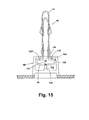
- Figure 15 is a partial cross sectional side elevational view of a sub-assembly of the fastener assembly of Figure 1 engaged with the dog-house assembly of Figure 13 ;
- Figure 16 is a partial cross sectional side elevational view of the fastener sub-assembly of Figure 15 after engagement with a vehicle body panel;
- Figure 17 is a partial cross sectional side elevational view of the fastener subassembly of Figure 15 after partial displacement away from the vehicle body panel;
- Figure 18 is a partial cross sectional side elevational view of the fastener subassembly of Figure 15 after full displacement away from the vehicle body panel;
- Figure 19 is a front elevational view of a second embodiment of a fastener of the present disclosure.
- Figure 20 is a side elevational view of the fastener of Figure 19 ;
- Figure 21 is a top plan view of the fastener of Figure 19 ;
- Figure 22 is a partial cross sectional side elevational view of an assembly of the fastener of Figure 19 to an automotive vehicle panel.
- a fastener assembly 10 includes a first member 12 which is releasably and slidably connected to a second member 14.
- First member 12 includes a rounded base 16 having rounded ends and substantially parallel, opposed first and second legs extending transversely from the rounded base 16.
- First leg 18 includes a first elastically flexible arm 22.
- second leg 20 includes a second elastically flexible arm 24.
- First leg 18 and first elastically flexible arm 22 are oriented as substantially a mirror image configuration of second leg 20 and second elastically flexible arm 24.
- First member 12 can be made of a metal such as spring steel, or from other materials including one or more polymeric materials.
- Second member 14 defines a U-shape and includes first and second body portions 26, 28 which are connected by first and second joining bands 30, 32.
- First and second joining bands 30, 32 are homogenous extensions of first and second body portions 26, 28.
- a first tab 34 and a second tab 36 are homogenous extensions of first body portion 26.
- First and second tabs 34, 36 are formed by a cutting, piercing, stamping, or similar operation performed on first body portion 26 and bent to extend from first body portion 26 toward second body portion 28.
- Second body portion 28 also includes each of a first and second tab 34', 36' which are not clearly visible in this view which are mirror images of first and second tabs 34, 36.
- First body portion 26 also includes each of a first, second, third, and fourth alignment dimple 38, 40, 42, 44.
- First and third alignment dimples 38, 42 are coaxially aligned with first tab 34.
- third and fourth alignment dimples 42, 44 are coaxially aligned with second tab 36.
- Second body portion 28 also includes each of a corresponding first, second, third, and fourth alignment dimples 38', 40', 42', 44' which are mirror image copies of first, second, third and fourth alignment dimples 38, 40, 42, 44.
- Second member 14 can be made of a metal such as spring steel similar to first member 12, or from other materials including one or more polymeric materials.
- First body portion 26 further includes a first engagement member 46 which extends to an opposite direction with respect to first and second tabs 34, 36.
- second body portion 28 includes a second engagement member 48 which is a mirror image configuration of first engagement member 46 and similarly extends away from second body portion 28 in an opposite direction with respect to first and second tabs 34', 36'.
- first member 12 further includes parallel first and second elongated tab receiving slots 50, 52.
- First and second elongated tab receiving slots 50, 52 extend in a direction transverse to rounded base 16 and are each created in first leg 18.
- second leg 20 includes each of a third and fourth elongated tab receiving slot 54, 56 which are mirror image configurations of first and second elongated tab receiving slots 50, 52.
- the elongated tab receiving slots 50, 52, 54, 56 are closed-ended slots and each include at least an end wall 53', 53", 53"', 53"" and opposed side walls 57, 59 respectively.
- Each of a first and second tab alignment member 58, 60 homogenously extend from a free end of first leg 18.
- each of a third and fourth tab alignment member 62, 64 homogenously extend beyond a free end of second leg 20.
- First and second tab alignment members 58, 60 are oriented at an angle with respect to first leg 18 and bent toward each of a third and fourth tab alignment member 62, 64 which each homogenously extend from second leg 20 in a mirror image of first and second tab alignment members 58, 60.
- first assembly alignment member 66 Positioned between first and second tab alignment members 58, 60 is a first assembly alignment member 66 which homogenously extends from first leg 18 and is commonly angled with respect to first and second tab alignment members 58, 60.
- second assembly alignment member 68 is positioned between each of third and fourth tab alignment members 62, 64 homogenously extending from second leg 20, and commonly angled with respect to third and fourth alignment members 62, 64 toward first assembly alignment member 66.
- first member 12 All of the features shown for first member 12 are created from various punching, stamping, bending, or other similar operations performed on a sheet or plate of material such as spring steel or commonly molded from a polymeric material in a single mold operation. Other metal materials or polymeric materials can be substituted for spring steel for either first member 12 or second member 14.
- Spring steel is selected for several embodiments of the present disclosure to provide a spring or bias force tending to retain first and second legs 18, 20 in the general configuration shown in Figure 2 during installation or subsequent use of fastener assembly 10.
- first member 12 can also include a cavity 70 created between first and second elongated tab receiving slots 50, 52 of first leg 18.
- first member 12 can also include a cavity 70' created in second leg 20 between third and fourth elongated tab receiving slots 54, 56.
- First member 12 has a first member height "A”, a first member base width "B”, a first member base height "C”, a leg spacing dimension "D”, a flexible arm non-deflected spacing "E”, and a first member length "F”.
- first member height "A” is approximately 27.0 mm
- first member base width "B” can be approximately 14.4 mm
- first member base height "C” can be approximately 3.2 mm
- leg spacing dimension “D” can be approximately 4.4 mm
- first member length "F” can be approximately 24.0 mm.
- Flexible arm non-deflected spacing "E” is a distance measurable between each of a first flexible arm convex portion 72 and a second flexible arm convex portion 76.
- flexible arm non-deflected spacing "E” can be approximately 7.8 mm.
- a first flexible arm concave portion 74 and a second flexible arm concave portion 78 are each created at a free end of first and second flexible arms 22, 24, respectively.
- each of the first, second, third, and fourth alignment dimples 38, 38', 40, 40', 42, 42', 44, 44' are created on outward facing surfaces of first and second body portions 26, 28.
- a rounded raised surface 80 is therefore created on each of the inward facing surfaces of first and second body portions 26, 28 (i.e.: the surfaces between first and second body portions 26, 28).
- a diameter "X" of each of the rounded raised surfaces 80 is smaller than a span width of the first, second, third, and fourth elongated tab receiving slots 50, 52, 54, 56 shown and described in reference to Figure 2 .
- Each of the rounded raised surfaces 80 are therefore intended to fit within the elongated tab receiving slots 50, 52, 54, 56 to help prevent rotation of the second member 14 when second member 14 is engaged with first member 12 to create fastener assembly 10 (described in reference to Figure 1 ).
- Each of the first and second engagement members 46, 48 also include a first engagement wing 82 and an opposed second engagement wing 84 which extend substantially transverse to a planar surface 85.
- a cavity 86, 86' is created in each of first and second body portions 26, 28 when first tabs 34, 34' are created.
- a cavity 88, 88' is created in each of first and second body portions 26, 28 when second tabs 36, 36' are created.
- second member 14 has a second member width "G" which is substantially equal to first member length "F" described in reference to Figure 5 .
- a second member slot 90 has a second member slot width "H” which allows second member 14 to be slidably received on first member 12 allowing clearance for each of the first and second flexible arms 22, 24.
- Second member 14 also has a second member height "J".
- second member width "G” is approximately 24.0 mm
- second member slot width "H” is approximately 8.0 mm
- second member height "J” is approximately 25.6 mm.
- the dimensions provided herein are for example only and can be modified at the discretion of the manufacturer to suit various sizes and geometries of fastener assemblies 10 of the present disclosure.
- First and second tabs 34, 34', 36, 36' are positioned proximate to free ends of each of first and second body portions 26, 28.
- the free ends of first and second body portions 26, 28 are separated by a first leg spacing dimension "K”.
- the first and second joining bands 30, 32 define a second leg spacing dimension "L”.
- first leg spacing dimension "K” is equal to or less than second leg spacing dimension "L” so that as second member 14 is engaged with first member 12 a spring or biasing force is created by temporary separation of first and second body portions 26, 28 which acts to elastically return first and second body portions 26, 28 to the configuration shown in Figure 8 when first and second tabs 34, 34', 36, 36' engage within the elongated tab receiving slots 50, 52, 54, 56 of first member 12 described in reference to Figure 2 .
- free ends of first and second engagement members 46, 48 are separated by an engagement member spacing dimension "M".
- first leg spacing dimension "K” is approximately 4.9 mm
- second leg spacing dimension "L” is approximately 5.3 mm
- engagement member spacing dimension "M” is approximately 9.3 mm.
- a tab extension dimension "N" of second tab 36 is representative of each of the first and second tabs 34, 34', 36, 36' such that each of the first and second tabs 34, 34', 36, 36' extend from first and second body portions 26, 28 by tab extension dimension "N".
- Both of the first and second engagement members 46, 48 have an engagement member width "P".
- tab extension dimension "N" is approximately 1.5 mm and engagement member width "P" is approximately 7.2 mm.
- second member 14 is shown aligned with but prior to engagement with first member 12.
- first tabs 34, 34', the first alignment dimples 38, 38', and the second alignment dimples 40, 40' are coaxially aligned along a first alignment axis defined through a center of both first and third elongated tab receiving slots 50, 54.
- second tabs 36, 36', third alignment dimples 42, 42', and fourth alignment dimples 44, 44' are coaxially aligned with a center of second and fourth elongated tab receiving slots 52, 56.
- first and second tabs 34, 34' and 36, 36' engage with corresponding ones of the first tab alignment member 58 and third tab alignment member 62, or with second tab alignment member 60 and fourth tab alignment member 64 respectively.
- first and second tabs 34, 34', 36, 36' Sliding engagement of the first and second tabs 34, 34', 36, 36' with the tab alignment members 58, 60, 62, 64 elastically deflects first body portion 26 away from second body portion 28 of second member 14 (by bending at first and second joining bands 30, 32) until by continued engagement in engagement direction "Q" the first and second tabs 34, 34', 36, 36' engage within the elongated tab receiving slots 50, 52, 54, 56. Thereafter, each of the first and second tabs 34, 34', 36, 36' can slide within their respective one of the elongated tab receiving slots 50, 52, 54, 56 allowing second member 14 to telescopically slide with respect to first member 12.
- first and second assembly alignment members 66, 68 are positioned proximate to a cavity 97 created between first and second joining bands 30, 32.
- first and second engagement members 46, 48 are freely deflectable within cavities 70, 70'.
- Fastener assembly 10 has a fastener assembly height "R" which according to several embodiments of the present disclosure is approximately 30.6 mm.
- a dog-house 98 can be homogenously connected to a member 99 such as a trim member adapted for installation on an automobile vehicle.
- Dog-house 98 is created from a polymeric material which can be co-molded with the member 99.
- Dog-house 98 includes a first wall 100 and an opposed second wall 102.
- a rear wall 103 together with first and second walls 100, 102 support an upper wall 104.
- a slot 106 is created in upper wall 104 so that dog-house 98 can slidably receive fastener assembly 10 (shown in reference to Figure 15 ).
- a lower wall 108 which is substantially parallel to upper wall 104 provides a beam 110 homogenously extending upwardly as viewed in Figure 13 from lower wall 108 and parallel to slot 106.
- Beam 110 includes a planar surface 111.
- An engagement tooth 114 is homogeneously created on surface 111 proximate to rear wall 103 and extends upwardly as viewed in Figure 13 away from surface 111.
- rounded base 16 of first member 12 of fastener assembly 10 includes an elongated slot 116 created in a substantially flat portion 117 of rounded base 16.
- An edge face 118 defining a first end of elongated slot 116 is provided to engage with the engagement tooth 114 described in reference to Figure 13 when fastener assembly 10 is slidably inserted into cavity 112 of dog-house 98.
- the engagement between edge face 118 and engagement tooth 114 provides a positive engagement of fastener assembly 10 within dog-house 98.
- fastener assembly 10 is shown following horizontal installation within cavity 112 of dog-house 98.
- the lower surface of rounded base 16 is in slidable contact with surface 111 of beam 110.
- an upper surface 120, 120' of rounded base 16 is frictionally engaged with a lower surface 122 of upper wall 104.
- the remaining portions of fastener assembly 10 extend freely and transversely away from dog-house 98 through slot 106.
- a sub-assembly 123 having fastener assembly 10 engaged with dog-house 98 can be used by inserting fastener assembly 10 starting at second member 14 into a longitudinal slot 124 created in a body panel 126 of an automobile vehicle (not shown).
- Fastener assembly 10 is inserted in an insertion direction "S" until an upper surface 128 of dog-house 98 contacts body panel 126.
- First engagement member 46 and second engagement member 48 both elastically deflect toward each other as they are inserted through longitudinal slot 124 then return to their normal extended positions. Subsequently, first and second flexible arms 22, 24 elastically deflect toward each other as first flexible arm convex portion 72 and second flexible arm convex portion 76 pass through longitudinal slot 124.
- First flexible arm concave portion 74 and second flexible arm concave portion 78 are each sized (e.g.: depth and length of curvature) to accommodate a plate thickness "T" of body panel 126.
- plate thickness "T” can range from approximately 0.8 mm to approximately 1.5 mm. This range can be increased or decreased by modifying the geometry of first and second flexible arm concave portions 74, 78.
- a pull force "Y" of approximately 50 pounds is required to displace dog-house 98 from body panel 126 by overcoming the biasing and static friction forces created by first and second flexible arm concave portions 74, 78.
- first and second tabs 34, 34', 36, 36' contact the end walls 53', 53", 53"', 53"" of the elongated tab receiving slots 50, 52, 54, 56 (not visible in this view).
- clearance dimension "V” is provided between body panel 126 and upper wall 104 of dog-house 98.
- clearance dimension "V” can be approximately 24.8 mm.
- Clearance dimension "V” allows manual access to squeeze together first and second body portions 26, 28 as well as first and second legs 18, 20 with a force to inwardly displace first and second engagement members 46, 48 so that first and second engagement members 46, 48 are drawn toward each other and can be withdrawn through longitudinal slot 124 of body panel 126 to completely remove fastener assembly 10 and dog-house 98 from body panel 126.
- Clearance dimension "V” can also provide for limited access between member 99 and body panel 126, for example for installation of electrical wires, tubing, and the like.
- a fastener 140 is created as a single piece, homogenously formed member.
- Fastener 140 includes a rounded base 142 having a flat portion 148 and an elongated aperture 150 similar to rounded base 16, and first and second legs 144, 146 extending substantially transverse to flat portion 148.
- a first flexible arm 152 homogenously connected to first leg 144 is created and oriented similar to first flexible arm 22, first flexible arm 152 having a first flexible arm convex portion 156 and a first flexible arm concave portion 158.
- first and second elastically displaceable engagement members 164, 166 are substantially identical in design and function to first and second engagement members 46, 48, except first and second engagement members 164, 166 are homogenously connected to first and second legs 144, 146 and are not displaceable with respect to rounded base 142.
- Fastener 140 has a fastener height "W”, a base width “Z”, a base height “AA”, and a base length “DD". According to several embodiments, fastener height “W”, base width “Z”, base height “AA”, and base length “DD” are substantially equal to first member height "A”, first member base width "B”, first member base height “C”, and first member length “F” respectively, of fastener assembly 10, so that fastener 140 can engage dog-house 98 and provides a similar space envelope for engagement with vehicle body panel 126. Fastener 140 further includes a flexible arm spacing dimension "BB”, and a flexible arm non-deflected spacing "CC”, which are similar to comparable dimensions of fastener assembly 10.
- fastener 140 is engaged within cavity 112 of dog-house 98 in the same manner as fastener assembly 10.
- An edge face (not shown) of elongated aperture 150 contacts engagement tooth 114 when rounded base 142 is slidably inserted into cavity 112 in a first direction facing away from the viewer as shown in Figure 22 .
- fastener 140 is loaded by pulling or forcing displacement of member 99 in a second direction by a force "Y" (downward as viewed in Figure 22 ) which is substantially transverse to the first direction for installation of fastener 140 in dog-house 98 described above.
- First and second flexible arms 152, 154 releasably engage the walls of aperture 124 of vehicle panel 126 in a first engaged position 168 similar to fastener assembly 10.
- First and second elastically displaceable engagement members 164, 166 contact vehicle body panel 126 in a second engagement position 170 similar to the intermediate engagement position shown in reference to Figure 17 .
- Fastener 140 does not provide the telescoping function of fastener assembly 10, therefore a clearance dimension "EE" between first and second engaged positions 168, 170 of vehicle body panel 126 is less than clearance dimension "V" provided by fastener assembly 10.
- Fastener 140 is also used in applications which can include displacement of vehicle member 99 due to expansion or activation of air bag 130. Similar to fastener assembly 10, a load or force of approximately 50 pounds is also required to displace dog-house 98 from the first engaged position 168 for fastener 140, and a load or force of approximately 200 pounds can be withstood by first and second elastically displaceable engagement members 164, 166 prior to yielding of the material of the engagement members 164, 166.
- member 99 can support or enclose an air bag assembly (not shown) for an automobile vehicle (not shown).
- an air bag assembly (not shown) for an automobile vehicle (not shown).
- a high retention capability of fastener assembly 10 is provided as a pull force defined as approximately 200 pounds or greater is required to yield the material of first and second engagement members 46, 48 or the first and second tabs 34, 34', 36, 36'. Therefore, deployment of the air bag will not cause displacement in displacement direction "U" of sub-assembly 123 in excess of clearance dimension "V", thus retaining member 99 in connection with body panel 126.
- a width "FF" of the slot 100 created in dog-house 98 is adapted to substantially equal or be slightly greater than a spacing between the flexible arm concave portions 74, 78, 158, 162 of fastener assembly 10 and fastener 140, but width "FF" is less than member base width "B” and base width "Z” of fastener assembly 10 and fastener 140.
- the legs (18, 20) of first member 12, and the second member 14 of fastener assembly 10, and the legs 144, 146 of fastener 140 can therefore extend outward of dog-house 98 through slot 106 of dog-house 98.
- Width "FF" prevents rounded base 16 of fastener assembly 10 or rounded base 142 of fastener 140 from being pulled out of cavity 112 when load "Y" is longitudinally or coaxially applied to the fastener (10, 140) which acts to move the rounded base (16, 142) and the dog-house 98 in displacement direction "U”.
- Fastener assemblies 10 of the present disclosure offer several advantages.
- a two-stage telescoping design of fastener assembly 10 provides a normally installed position having fastener assembly 10 fully inserted within a body panel of an automobile vehicle.
- the fastener assembly and dog-house are engaged with a body panel of a vehicle.
- a telescoping or sliding motion of the first and second members 12, 14 of fastener assembly 10 occurs.
- a frictional sliding displacement is restrained at a second stage or position by contact between first and second tabs 34, 34', 36, 36' of second member 14 contacting end walls of tab receiving slots created in first member 12.
- the second, displaced position of fastener assembly 10 allows for manual removal of fastener assembly 10 in addition to providing a clearance space between the member 99 and the body panel 126. Dimples created through the first and second body portions 26, 28 of second member 14 which are positioned within the elongated tab receiving slots of first member 12 provide for fastener assembly alignment and prevent rotation of second member 14 with respect to the first member 12.
- fastener assembly 10 By frictionally engaging a rounded base of fastener assembly 10 within the dog-house, fastener assembly 10 can be slidably fit into the dog-house in a first or horizontal direction. This engagement position prevents withdrawal of the fastener assembly in a second or longitudinal direction of the fastener assembly which is the direction of load application upon release of an air bag assembly.
- This connection of the rounded base into or within a cavity of the dog-house improves on fastener designs having bight members within the fastener which externally engage a spade or blade member extending away from a trim member body, but which can release upon application of an air bag deployment load.
- the rounded base can be manually removed from the dog-house by sliding in an opposite direction from the installation direction, but the second direction is still transverse to the load direction applied during air bag deployment.
- the fastener assembly 10 can also be releasably removed from its second stage engagement with the dog-house by inserting a tool such as a screwdriver into the dog-house and prying the rounded base away from its engagement with the engagement tooth of the dog-house. This provides for complete replacement of fastener assembly 10 and/or complete replacement of member 99.
- the invention relates to:
Abstract
Description
- The present disclosure relates to automobile fastener clips used to join components to a vehicle body.
- The statements in this section merely provide background information related to the present disclosure and may not constitute prior art.
- For automotive applications, fasteners are used to join trim or panel members to sections or metal body portions of the automobile. The requirements for these fasteners are that they be insertable into apertures of the automobile and meet requirements to both retain the component as well as provide a minimum pullout retention force such that the component is retained under given load conditions but can be removed without damaging the component. Common fastener designs include directly opposed flexible wings which deflect inwardly upon insertion of the fastener and expand by spring force to hold the fastener within an aperture such as a slot in the automobile.
- A drawback of commonly used fasteners occurs for certain applications, including fasteners used to mount trim or instrument panels, or for trim components which cover air bags. In the first instance, it is common that access to the space behind the trim or instrument panel is desired, however removal of the entire trim piece or panel may be undesirable due to weight or realignment concerns. For trim member applications covering an air bag, deployment of the air bag often displaces the trim component, however, it is undesirable for the trim component to freely disassociate from the body portion of the automobile. To prevent disassociation, fasteners have been created having two-part assemblies, with one part connected to the vehicle body and the second part connected to the trim component or panel member. These fastener designs commonly include a tether which allows the trim or panel component to displace while preventing disassociation from the first part and therefore from the vehicle body. A drawback of these fastener designs is the tether only loosely retains the trim or panel member which can still result in realignment problems, or inadvertent disconnection of electrical connectors, or the like.
- According to several embodiments of the present invention, a fastener system for use with an air bag has a fastener including a rounded base having a flat portion, and first and second arms oriented transverse to the flat portion. A first set of vehicle panel engagement devices is connected to the fastener proximate to the rounded base. A second set of vehicle panel engagement devices is connected to the fastener spatially separated from both the first set of vehicle panel engagement devices and the rounded base. A vehicle component has a dog-house homogenously connected thereto. The rounded base is slidably received within and engaged with the dog-house to releasably connect the fastener to the vehicle component. The vehicle component is adapted to be displaceable upon deployment of an air bag.
- According to further embodiments, a fastener assembly includes a first member having first and second arms each including first and second elongated slots. A second member is slidingly engaged with the first member, the second member having first and second body portions each including first and second tabs extending toward an opposite one of the first and second body portions. A plurality of dimples are created on each of the first and second body portions. The plurality of dimples of the first body portion extend into the first and second elongated slots of the first arm in a first engaged position of the first and second members, and the plurality of dimples of the second body portion extend into the first and second elongated slots of the second arm in the first engaged position. The first and second tabs of the first body portion are slidingly positioned within the first and second elongated slots of the first arm, and the first and second tabs of the second body portion are slidingly positioned within the first and second elongated slots of the second arm.
- According to further embodiments, a telescoped second engaged position of the fastener assembly has the first and second tabs of the first body portion each in contact with an end wall of the first and second elongated slots of the first arm, and the first and second tabs of the second body portion each in contact with an end wall of the first and second elongated slots of the second arm. The telescoped second position also has the plurality of dimples of each of the first and second body portions displaced out of the first and second elongated slots of both the first and second members.
- According to further embodiments, a fastener system includes a first member having a rounded base having a flat portion and first and second arms oriented transverse to the flat portion. The first and second arms each include first and second elongated slots. A second member is slidingly engaged with the first member. The second member has first and second body portions each including first and second tabs extending toward an opposite one of the first and second body portions. Each of the first and second tabs are slidingly received in one of the first or second slots allowing the second member to slide in a first direction away from the rounded base. A dog-house is homogenously connected to a polymeric member. The dog-house receives and engages the rounded base in a second direction transverse to the first direction.
- Further areas of applicability will become apparent from the description provided herein. It should be understood that the description and specific examples are intended for purposes of illustration only and are not intended to limit the scope of the present disclosure.
- The drawings described herein are for illustration purposes only and are not intended to limit the scope of the present disclosure in any way.
-
Figure 1 is front perspective view of a fastener assembly for a two stage, telescoping high retention fastener of the present disclosure; -
Figure 2 is front perspective view of a first member of the fastener assembly ofFigure 1 ; -
Figure 3 is a front elevational view of the first member ofFigure 2 ; -
Figure 4 is a side elevational view of the first member ofFigure 2 ; -
Figure 5 is a top plan view of the first member ofFigure 2 ; -
Figure 6 is front perspective view of a second member of the fastener assembly ofFigure 1 ; -
Figure 7 is a front elevational view of the second member ofFigure 6 ; -
Figure 8 is a side elevational view of the second member ofFigure 6 ; -
Figure 9 is a top plan view of the second member ofFigure 6 ; -
Figure 10 is a front elevational view showing a pre-assembled condition of the fastener assembly ofFigure 1 ; -
Figure 11 is a front elevational view of the fastener assembly ofFigure 1 ; -
Figure 12 is a side elevational view of the fastener assembly ofFigure 1 ; -
Figure 13 is a partial cross sectional front perspective view of a dog-house assembly adapted to receive the fastener assembly ofFigure 1 ; -
Figure 14 is a bottom perspective view of the fastener assembly ofFigure 1 ; -
Figure 15 is a partial cross sectional side elevational view of a sub-assembly of the fastener assembly ofFigure 1 engaged with the dog-house assembly ofFigure 13 ; -
Figure 16 is a partial cross sectional side elevational view of the fastener sub-assembly ofFigure 15 after engagement with a vehicle body panel; -
Figure 17 is a partial cross sectional side elevational view of the fastener subassembly ofFigure 15 after partial displacement away from the vehicle body panel; -
Figure 18 is a partial cross sectional side elevational view of the fastener subassembly ofFigure 15 after full displacement away from the vehicle body panel; -
Figure 19 is a front elevational view of a second embodiment of a fastener of the present disclosure; -
Figure 20 is a side elevational view of the fastener ofFigure 19 ; -
Figure 21 is a top plan view of the fastener ofFigure 19 ; and -
Figure 22 is a partial cross sectional side elevational view of an assembly of the fastener ofFigure 19 to an automotive vehicle panel. - The following description is merely exemplary in nature and is not intended to limit the present disclosure, application, or uses. It should be understood that throughout the drawings, corresponding reference numerals indicate like or corresponding parts and features.
- Referring to
Figure 1 , afastener assembly 10 includes afirst member 12 which is releasably and slidably connected to asecond member 14.First member 12 includes arounded base 16 having rounded ends and substantially parallel, opposed first and second legs extending transversely from therounded base 16.First leg 18 includes a first elasticallyflexible arm 22. Similarly,second leg 20 includes a second elasticallyflexible arm 24.First leg 18 and first elasticallyflexible arm 22 are oriented as substantially a mirror image configuration ofsecond leg 20 and second elasticallyflexible arm 24.First member 12 can be made of a metal such as spring steel, or from other materials including one or more polymeric materials. -
Second member 14 defines a U-shape and includes first andsecond body portions bands bands second body portions first tab 34 and asecond tab 36 are homogenous extensions offirst body portion 26. First andsecond tabs first body portion 26 and bent to extend fromfirst body portion 26 towardsecond body portion 28.Second body portion 28 also includes each of a first and second tab 34', 36' which are not clearly visible in this view which are mirror images of first andsecond tabs First body portion 26 also includes each of a first, second, third, andfourth alignment dimple first tab 34. Similarly, third and fourth alignment dimples 42, 44 are coaxially aligned withsecond tab 36.Second body portion 28 also includes each of a corresponding first, second, third, and fourth alignment dimples 38', 40', 42', 44' which are mirror image copies of first, second, third and fourth alignment dimples 38, 40, 42, 44.Second member 14 can be made of a metal such as spring steel similar tofirst member 12, or from other materials including one or more polymeric materials. -
First body portion 26 further includes afirst engagement member 46 which extends to an opposite direction with respect to first andsecond tabs second body portion 28 includes asecond engagement member 48 which is a mirror image configuration offirst engagement member 46 and similarly extends away fromsecond body portion 28 in an opposite direction with respect to first and second tabs 34', 36'. - Referring to
Figure 2 ,first member 12 further includes parallel first and second elongatedtab receiving slots tab receiving slots base 16 and are each created infirst leg 18. Similarly,second leg 20 includes each of a third and fourth elongatedtab receiving slot tab receiving slots tab receiving slots end wall 53', 53", 53"', 53"" and opposedside walls tab alignment member first leg 18. Similarly, each of a third and fourthtab alignment member second leg 20. First and secondtab alignment members first leg 18 and bent toward each of a third and fourthtab alignment member second leg 20 in a mirror image of first and secondtab alignment members - Positioned between first and second
tab alignment members assembly alignment member 66 which homogenously extends fromfirst leg 18 and is commonly angled with respect to first and secondtab alignment members assembly alignment member 68 is positioned between each of third and fourthtab alignment members second leg 20, and commonly angled with respect to third andfourth alignment members assembly alignment member 66. - All of the features shown for
first member 12 are created from various punching, stamping, bending, or other similar operations performed on a sheet or plate of material such as spring steel or commonly molded from a polymeric material in a single mold operation. Other metal materials or polymeric materials can be substituted for spring steel for eitherfirst member 12 orsecond member 14. Spring steel is selected for several embodiments of the present disclosure to provide a spring or bias force tending to retain first andsecond legs Figure 2 during installation or subsequent use offastener assembly 10. - Referring to
Figures 3-5 ,first member 12 can also include a cavity 70 created between first and second elongatedtab receiving slots first leg 18. Similarly,first member 12 can also include a cavity 70' created insecond leg 20 between third and fourth elongatedtab receiving slots First member 12 has a first member height "A", a first member base width "B", a first member base height "C", a leg spacing dimension "D", a flexible arm non-deflected spacing "E", and a first member length "F". According to several embodiments, first member height "A" is approximately 27.0 mm, first member base width "B" can be approximately 14.4 mm, first member base height "C" can be approximately 3.2 mm, leg spacing dimension "D" can be approximately 4.4 mm, and first member length "F" can be approximately 24.0 mm. Flexible arm non-deflected spacing "E" is a distance measurable between each of a first flexible armconvex portion 72 and a second flexible armconvex portion 76. According to several embodiments, flexible arm non-deflected spacing "E" can be approximately 7.8 mm. A first flexible armconcave portion 74 and a second flexible armconcave portion 78 are each created at a free end of first and secondflexible arms - Referring to
Figure 6 and again toFigure 2 , each of the first, second, third, and fourth alignment dimples 38, 38', 40, 40', 42, 42', 44, 44' are created on outward facing surfaces of first andsecond body portions surface 80 is therefore created on each of the inward facing surfaces of first andsecond body portions 26, 28 (i.e.: the surfaces between first andsecond body portions 26, 28). A diameter "X" of each of the rounded raisedsurfaces 80 is smaller than a span width of the first, second, third, and fourth elongatedtab receiving slots Figure 2 . Each of the rounded raisedsurfaces 80 are therefore intended to fit within the elongatedtab receiving slots second member 14 whensecond member 14 is engaged withfirst member 12 to create fastener assembly 10 (described in reference toFigure 1 ). Each of the first andsecond engagement members first engagement wing 82 and an opposedsecond engagement wing 84 which extend substantially transverse to aplanar surface 85. Acavity 86, 86' is created in each of first andsecond body portions first tabs 34, 34' are created. Similarly, acavity 88, 88' is created in each of first andsecond body portions second tabs 36, 36' are created. - Referring to
Figures 7-9 and again toFigure 1 ,second member 14 has a second member width "G" which is substantially equal to first member length "F" described in reference toFigure 5 . Asecond member slot 90 has a second member slot width "H" which allowssecond member 14 to be slidably received onfirst member 12 allowing clearance for each of the first and secondflexible arms Second member 14 also has a second member height "J". According to several embodiments, second member width "G" is approximately 24.0 mm, second member slot width "H" is approximately 8.0 mm, and second member height "J" is approximately 25.6 mm. The dimensions provided herein are for example only and can be modified at the discretion of the manufacturer to suit various sizes and geometries offastener assemblies 10 of the present disclosure. - First and
second tabs second body portions second body portions bands second member 14 is engaged with first member 12 a spring or biasing force is created by temporary separation of first andsecond body portions second body portions Figure 8 when first andsecond tabs tab receiving slots first member 12 described in reference toFigure 2 . In the non-deflected state shown inFigure 8 , free ends of first andsecond engagement members - Referring more specifically to
Figure 9 , a tab extension dimension "N" ofsecond tab 36 is representative of each of the first andsecond tabs second tabs second body portions second engagement members - Referring to
Figures 10 through 12 ,second member 14 is shown aligned with but prior to engagement withfirst member 12. Each of thefirst tabs 34, 34', the first alignment dimples 38, 38', and the second alignment dimples 40, 40' are coaxially aligned along a first alignment axis defined through a center of both first and third elongatedtab receiving slots second tabs 36, 36', third alignment dimples 42, 42', and fourth alignment dimples 44, 44' are coaxially aligned with a center of second and fourth elongatedtab receiving slots second member 14 is slidingly engaged withfirst member 12 in an engagement direction "Q", first andsecond tabs tab alignment member 58 and thirdtab alignment member 62, or with secondtab alignment member 60 and fourthtab alignment member 64 respectively. - Sliding engagement of the first and
second tabs tab alignment members first body portion 26 away fromsecond body portion 28 of second member 14 (by bending at first and second joiningbands 30, 32) until by continued engagement in engagement direction "Q" the first andsecond tabs tab receiving slots second tabs tab receiving slots second member 14 to telescopically slide with respect tofirst member 12. Continued engagement ofsecond member 14 in engagement direction "Q" positions the alignment dimples 38, 38', 40, 40', 42, 42', 44, 44' in respective ones of the elongatedtab receiving slots second member 14 with respect tofirst member 12. Whensecond member 14 is fully engaged withfirst member 12, both first and secondassembly alignment members cavity 97 created between first and second joiningbands - Referring more specifically to
Figures 11 and 12 , in the assembled condition offastener assembly 10, first andsecond engagement members Fastener assembly 10 has a fastener assembly height "R" which according to several embodiments of the present disclosure is approximately 30.6 mm. - Referring now to
Figure 13 , a dog-house 98 can be homogenously connected to amember 99 such as a trim member adapted for installation on an automobile vehicle. Dog-house 98 is created from a polymeric material which can be co-molded with themember 99. Dog-house 98 includes afirst wall 100 and an opposedsecond wall 102. Arear wall 103 together with first andsecond walls upper wall 104. Aslot 106 is created inupper wall 104 so that dog-house 98 can slidably receive fastener assembly 10 (shown in reference toFigure 15 ). Alower wall 108 which is substantially parallel toupper wall 104 provides abeam 110 homogenously extending upwardly as viewed inFigure 13 fromlower wall 108 and parallel to slot 106.Beam 110 includes aplanar surface 111. First andsecond walls rear wall 103,upper wall 104, andlower wall 108, together define acavity 112. Anengagement tooth 114 is homogeneously created onsurface 111 proximate torear wall 103 and extends upwardly as viewed inFigure 13 away fromsurface 111. - Referring to
Figure 14 and again toFigure 13 , roundedbase 16 offirst member 12 offastener assembly 10 includes anelongated slot 116 created in a substantiallyflat portion 117 of roundedbase 16. Anedge face 118 defining a first end ofelongated slot 116 is provided to engage with theengagement tooth 114 described in reference toFigure 13 whenfastener assembly 10 is slidably inserted intocavity 112 of dog-house 98. The engagement betweenedge face 118 andengagement tooth 114 provides a positive engagement offastener assembly 10 within dog-house 98. - Referring to
Figure 15 ,fastener assembly 10 is shown following horizontal installation withincavity 112 of dog-house 98. In this position, the lower surface of roundedbase 16 is in slidable contact withsurface 111 ofbeam 110. At the same time, anupper surface 120, 120' of roundedbase 16 is frictionally engaged with alower surface 122 ofupper wall 104. The remaining portions offastener assembly 10 extend freely and transversely away from dog-house 98 throughslot 106. - Referring to
Figure 16 , a sub-assembly 123 havingfastener assembly 10 engaged with dog-house 98 can be used by insertingfastener assembly 10 starting atsecond member 14 into alongitudinal slot 124 created in abody panel 126 of an automobile vehicle (not shown).Fastener assembly 10 is inserted in an insertion direction "S" until anupper surface 128 of dog-house 98contacts body panel 126.First engagement member 46 andsecond engagement member 48 both elastically deflect toward each other as they are inserted throughlongitudinal slot 124 then return to their normal extended positions. Subsequently, first and secondflexible arms convex portion 72 and second flexible armconvex portion 76 pass throughlongitudinal slot 124. Whenbody panel 126 is in contact withupper surface 128, first and secondflexible arms concave portion 74 and second flexible armconcave portion 78 individually contact opposed side walls oflongitudinal slot 124. First flexible armconcave portion 74 and second flexible armconcave portion 78 are each sized (e.g.: depth and length of curvature) to accommodate a plate thickness "T" ofbody panel 126. According to several embodiments, plate thickness "T" can range from approximately 0.8 mm to approximately 1.5 mm. This range can be increased or decreased by modifying the geometry of first and second flexible armconcave portions sub-assembly 123 of dog-house 98 andfastener assembly 10 in contact withbody panel 126, a pull force "Y" of approximately 50 pounds is required to displace dog-house 98 frombody panel 126 by overcoming the biasing and static friction forces created by first and second flexible armconcave portions - Referring to
Figure 17 , when the pull force "Y" of approximately 50 pounds has been achieved, for example by expansion or release of anair bag 130 positioned behind or in contact withmember 99, separation betweensub-assembly 123 having dog-house 98 andfastener assembly 10 can occur with dog-house 98 andmember 99 moving in a displacement direction "U" with respect tobody panel 126. Displacement in displacement direction "U" continues untilbody panel 126 contacts first andsecond engagement members first member 12 is still in complete engagement withsecond member 14 such that first andsecond tabs flexible arms - Referring to
Figure 18 , afterbody panel 126 contacts first andsecond engagement members house 98 in displacement direction "U" causes a sliding displacement betweensecond member 14 andfirst member 12 with each of the first andsecond tabs tab receiving slots second legs first member 12 with respect tosecond member 14 forces first, second, third, and fourth alignment dimples 38, 40, 42, 44 to displace from the elongatedtab receiving slots first member 12 with respect tosecond member 14 continues until first andsecond tabs end walls 53', 53", 53"', 53"" of the elongatedtab receiving slots - At this time, a clearance dimension "V" is provided between
body panel 126 andupper wall 104 of dog-house 98. According to several embodiments, clearance dimension "V" can be approximately 24.8 mm. Clearance dimension "V" allows manual access to squeeze together first andsecond body portions second legs second engagement members second engagement members longitudinal slot 124 ofbody panel 126 to completely removefastener assembly 10 and dog-house 98 frombody panel 126. Clearance dimension "V" can also provide for limited access betweenmember 99 andbody panel 126, for example for installation of electrical wires, tubing, and the like. - Referring to
Figures 19 through 21 and again toFigure 1 , according to additional embodiments afastener 140 is created as a single piece, homogenously formed member.Fastener 140 includes arounded base 142 having aflat portion 148 and anelongated aperture 150 similar torounded base 16, and first andsecond legs flat portion 148. A firstflexible arm 152 homogenously connected tofirst leg 144 is created and oriented similar to firstflexible arm 22, firstflexible arm 152 having a first flexible armconvex portion 156 and a first flexible armconcave portion 158. Similarly, a secondflexible arm 154 homogenously connected tosecond leg 146 is created and oriented similar to secondflexible arm 24, secondflexible arm 154 having a second flexible armconvex portion 160 and a second flexible armconcave portion 162. First and second elasticallydisplaceable engagement members second engagement members second engagement members second legs base 142. -
Fastener 140 has a fastener height "W", a base width "Z", a base height "AA", and a base length "DD". According to several embodiments, fastener height "W", base width "Z", base height "AA", and base length "DD" are substantially equal to first member height "A", first member base width "B", first member base height "C", and first member length "F" respectively, offastener assembly 10, so thatfastener 140 can engage dog-house 98 and provides a similar space envelope for engagement withvehicle body panel 126.Fastener 140 further includes a flexible arm spacing dimension "BB", and a flexible arm non-deflected spacing "CC", which are similar to comparable dimensions offastener assembly 10. - Referring to
Figure 22 and again toFigures 15-18 ,fastener 140 is engaged withincavity 112 of dog-house 98 in the same manner asfastener assembly 10. An edge face (not shown) ofelongated aperture 150contacts engagement tooth 114 when roundedbase 142 is slidably inserted intocavity 112 in a first direction facing away from the viewer as shown inFigure 22 . Similar tofastener assembly 10,fastener 140 is loaded by pulling or forcing displacement ofmember 99 in a second direction by a force "Y" (downward as viewed inFigure 22 ) which is substantially transverse to the first direction for installation offastener 140 in dog-house 98 described above. First and secondflexible arms aperture 124 ofvehicle panel 126 in a firstengaged position 168 similar tofastener assembly 10. First and second elasticallydisplaceable engagement members vehicle body panel 126 in asecond engagement position 170 similar to the intermediate engagement position shown in reference toFigure 17 . -
Fastener 140 does not provide the telescoping function offastener assembly 10, therefore a clearance dimension "EE" between first and secondengaged positions vehicle body panel 126 is less than clearance dimension "V" provided byfastener assembly 10.Fastener 140 is also used in applications which can include displacement ofvehicle member 99 due to expansion or activation ofair bag 130. Similar tofastener assembly 10, a load or force of approximately 50 pounds is also required to displace dog-house 98 from the firstengaged position 168 forfastener 140, and a load or force of approximately 200 pounds can be withstood by first and second elasticallydisplaceable engagement members engagement members - According to several embodiments,
member 99 can support or enclose an air bag assembly (not shown) for an automobile vehicle (not shown). During deployment of the air bag, the fully installed position offastener assembly 10 inbody panel 126 as shown in reference toFigure 16 will change to the fully extended position shown in reference toFigure 18 having clearance dimension "V". A high retention capability offastener assembly 10 is provided as a pull force defined as approximately 200 pounds or greater is required to yield the material of first andsecond engagement members second tabs sub-assembly 123 in excess of clearance dimension "V", thus retainingmember 99 in connection withbody panel 126. - Referring again to
Figures 4 ,13 ,17 ,20 , and22 , a width "FF" of theslot 100 created in dog-house 98 is adapted to substantially equal or be slightly greater than a spacing between the flexible armconcave portions fastener assembly 10 andfastener 140, but width "FF" is less than member base width "B" and base width "Z" offastener assembly 10 andfastener 140. The legs (18, 20) offirst member 12, and thesecond member 14 offastener assembly 10, and thelegs fastener 140 can therefore extend outward of dog-house 98 throughslot 106 of dog-house 98. Width "FF", however, prevents roundedbase 16 offastener assembly 10 or roundedbase 142 offastener 140 from being pulled out ofcavity 112 when load "Y" is longitudinally or coaxially applied to the fastener (10, 140) which acts to move the rounded base (16, 142) and the dog-house 98 in displacement direction "U". -
Fastener assemblies 10 of the present disclosure offer several advantages. A two-stage telescoping design offastener assembly 10 provides a normally installed position havingfastener assembly 10 fully inserted within a body panel of an automobile vehicle. In a first stage or position, the fastener assembly and dog-house are engaged with a body panel of a vehicle. By pulling with or exerting a force greater than approximately 50 pounds onmember 99 tending to pullmember 99 away from thebody panel 126 of the vehicle, a telescoping or sliding motion of the first andsecond members fastener assembly 10 occurs. A frictional sliding displacement is restrained at a second stage or position by contact between first andsecond tabs second member 14 contacting end walls of tab receiving slots created infirst member 12. The second, displaced position offastener assembly 10 allows for manual removal offastener assembly 10 in addition to providing a clearance space between themember 99 and thebody panel 126. Dimples created through the first andsecond body portions second member 14 which are positioned within the elongated tab receiving slots offirst member 12 provide for fastener assembly alignment and prevent rotation ofsecond member 14 with respect to thefirst member 12. - By frictionally engaging a rounded base of
fastener assembly 10 within the dog-house,fastener assembly 10 can be slidably fit into the dog-house in a first or horizontal direction. This engagement position prevents withdrawal of the fastener assembly in a second or longitudinal direction of the fastener assembly which is the direction of load application upon release of an air bag assembly. This connection of the rounded base into or within a cavity of the dog-house improves on fastener designs having bight members within the fastener which externally engage a spade or blade member extending away from a trim member body, but which can release upon application of an air bag deployment load. In the present disclosure, the rounded base can be manually removed from the dog-house by sliding in an opposite direction from the installation direction, but the second direction is still transverse to the load direction applied during air bag deployment. Thefastener assembly 10 can also be releasably removed from its second stage engagement with the dog-house by inserting a tool such as a screwdriver into the dog-house and prying the rounded base away from its engagement with the engagement tooth of the dog-house. This provides for complete replacement offastener assembly 10 and/or complete replacement ofmember 99. - In summary, the invention relates to:
- 1. A fastener system for use with an air bag, comprising:
- a fastener including a rounded base having rounded ends extending from a flat portion, and first and second arms oriented transverse to the flat portion;
- a first set of vehicle panel engagement devices connected to the fastener proximate to the rounded base;
- a second set of vehicle panel engagement devices connected to the fastener spatially separated from both the first set of vehicle panel engagement devices and the rounded base; and
- a vehicle component having a dog-house homogenously connected thereto, the rounded base adapted to be slidably received within a dog-house cavity and engaged with the dog-house to releasably connect the fastener to the vehicle component, the vehicle component adapted to be displaceable upon deployment of an air bag from a first engagement position having the first set of engagement devices engaged with a vehicle body panel to a second engagement position having the second set of vehicle panel engagement devices engaged with the vehicle body panel.
- 2. The fastener system of
item 1, wherein the flat portion of the rounded base includes an elongated aperture created in the flat portion having an edge face. - 3. The fastener system of item 2, wherein the dog-house includes an engagement tooth adapted to contact the edge face to positively engage the fastener with the dog-house.
- 4. The fastener system of any of items 1 - 3, wherein the dog-house includes a plurality of walls defining the cavity, the rounded base of the fastener adapted to be slidably received within the cavity in a first direction, wherein the vehicle component is displaceable in a second direction transverse to the first direction.
- 5. The fastener system of any of items 1 - 4, wherein the second engaged position having the second set of engagement devices in contact with the vehicle body panel follows deployment of the air bag in contact with the vehicle component and displacement of the vehicle component with respect to the vehicle body panel, the second engaged position operating to prevent further movement of the vehicle body panel with respect to the rounded base of the fastener, the fastener being removable from the vehicle body panel in the second engaged position by displacing the first and second legs toward each other within a clearance created between the dog-house and the vehicle body panel.
- 6. The fastener system of any of items 1-5, wherein the first set of vehicle panel engagement devices includes:
- a first flexible arm homogenously connected to the first arm proximate to the rounded base; and
- a second flexible arm homogenously connected to the second arm, the first flexible arm defining a mirror image of the second flexible arm proximate to the rounded base.
- 7. The fastener system of any of items 1 - 6, wherein the second set of vehicle panel engagement devices includes:
- a first engagement member homogenously connected to the first arm spatially separated from both the first flexible arm and the rounded base;
and - a second engagement member homogenously connected to the second arm spatially separated from both the second flexible arm and the rounded base, the second engagement member defining a mirror image of the first engagement member.
- a first engagement member homogenously connected to the first arm spatially separated from both the first flexible arm and the rounded base;
- 8. The fastener system of any of items 1 - 7, wherein the fastener includes a second member having opposed first and second body portions each slidably connected to one of the first and second arms using at least one tab extending from each of the first and second body portions slidably received in a longitudinal slot created in each of the first and second arms.
- 9. A fastener assembly, particularly according to any of items 1 - 8, comprising:
- a first member having first and second arms each including first and second elongated slots;
- a second member slidingly engaged with the first member, the second member having first and second body portions each including first and second tabs extending toward an opposite one of the first and second body portions; and
- a plurality of dimples created on each of the first and second body portions, the plurality of dimples of the first body portion extending into the first and second elongated slots of the first arm in a first engaged position of the first and second members, and the plurality of dimples of the second body portion extending into the first and second elongated slots of the second arm in the first engaged position.
- 10. The fastener assembly of item 9, wherein the first and second tabs of the first body portion are slidingly positioned within the first and second elongated slots of the first arm and the first and second tabs of the second body portion are slidingly positioned within the first and second elongated slots of the second arm.
- 11. The fastener assembly of
item 10, further including a telescoped second engaged position of the fastener assembly having the first and second tabs of the first body portion each in contact with an end wall of the first and second elongated slots of the first arm, and the first and second tabs of the second body portion each in contact with an end wall of the first and second elongated slots of the second arm, the telescoped second position also having the plurality of dimples of each of the first and second body portions displaced out of the first and second elongated slots of both the first and second members. - 12. The fastener assembly of any of items 9 - 11, further including first and second joining bands homogenously joining the first and second body portions such that the second member defines a substantially U-shape.
- 13. The fastener assembly of item 12:
- wherein the first and second body portions proximate to the first and second joining bands are separated by a first spacing dimension; and
- wherein the first and second body portions opposite to the first and second joining bands are separated by a second spacing dimension, the second spacing dimension being less than the first spacing dimension such that contact between the first body portion and the first member and between the second body portion and the second member extends the first and second body portions opposite to the first and second joining bands outwardly to substantially equal the first spacing dimension, creating a biasing force adapted to retain the first and second tabs within the first and second elongated slots.
- 14. The fastener assembly of any of items 9-13, wherein the plurality of dimples operate to prevent rotation of the second member with respect to the first member by contact between the plurality of dimples and opposed walls of the elongated slots in the first engaged position.
- 15. The fastener assembly of any of items 9-14, wherein the first and second arms of the first member are parallel to each other and the first arm defines a mirror image of the second arm.
- 16. The fastener assembly of any of items 9-15, wherein the first member includes a rounded base having a flat portion, the first and second arms being oriented transverse to the flat portion.
- 17. The fastener assembly of any of items 9-16, further including:
- a first flexible arm homogenously connected to the first arm; and
- a second flexible arm homogenously connected to the second arm, the second flexible arm defining a mirror image of the first flexible arm.
- 18. The fastener assembly of any of items 9-17, wherein each of the first and second body portions include tab alignment members each adapted to slidingly contact one of the first and second tabs of individual ones of the first and second body portions to align the first and second tabs with individual ones of the first and second elongated slots when the first and second members are engaged.
- 19. The fastener assembly of
item 18, wherein the tab alignment members are oriented at an angle with respect to the first and second body portions. - 20. A fastener system for connection to a vehicle component, particularly according to any of items 1 - 19, comprising:
- a fastener including:
- a first member having a rounded base having a flat portion and first and second arms oriented transverse to the flat portion, the first and second arms each including first and second elongated slots; and
- a second member slidingly engaged with the first member, the second member having first and second body portions each including first and second tabs extending toward an opposite one of the first and second body portions, each of the first and second tabs slidingly received in one of the first or second slots allowing the second member to slide in a first direction away from the rounded base; and
- a dog-house homogenously connected to a vehicle component, the dog-house adapted to receive the rounded base in a second direction transverse to the first direction.
- a fastener including:
- 21. The fastener system of
item 20, wherein the fastener includes a plurality of dimples created on each of the first and second body portions. - 22. The fastener system of item 21, wherein the plurality of dimples of the first body portion extend into the first and second elongated slots of the first arm in a first engaged position of the first and second members, and the plurality of dimples of the second body portion extending into the first and second elongated slots of the second arm in the first engaged position.
- 23. The fastener system of
item 21 or 22, further including a telescoped second engaged position of the first and second members having the first and second tabs of the first body portion each in contact with an end wall of the first and second elongated slots of the first arm, and the first and second tabs of the second body portion each in contact with an end wall of the first and second elongated slots of the second arm. - 24. The fastener system of any of items 20 - 23, further including:
- a first flexible arm homogenously connected to the first arm; and
- a second engagement member homogenously connected to the second body portion and spatially separated from both the second flexible arm and the rounded base, the second engagement member defining a mirror image of the first engagement member.
- 25. The fastener system of
item 24, further including:- a first engagement member homogenously connected to the first body portion and spatially separated from both the first flexible arm and the rounded base; and
- a second engagement member homogenously connected to the second body portion and spatially separated from both the second flexible arm and the rounded base, the second engagement member defining a mirror image of the first engagement member.
- 26. The fastener system of item 25, further including:
- a vehicle body panel having an aperture adapted to receive the fastener; and
- an air bag operating to displace the vehicle component from a first fastener engaged position to a second fastener engaged position.
- 27. The fastener system of item 26:
- wherein in the first fastener engaged position the first and second flexible arms are releasably engaged with the vehicle body panel; and
- wherein in the second fastener engaged position the first and second engagement members are engaged with the vehicle body panel.
- 28. The fastener system of item 27:
- wherein in the first fastener engaged position a force of approximately 50 pounds longitudinally applied to the fastener is required to release the first and second flexible arms from engagement with the vehicle body panel; and
- wherein in the second fastener engaged position a second force of approximately 200 pounds longitudinally applied to the fastener is required to yield the first and second engagement members.
- 29. The fastener system of any of items 20 - 28:
- wherein the fastener includes a plurality of dimples created on each of the first and second body portions, the plurality of dimples positioned within the first and second elongated slots of the first and second arms in a first engaged position of the fastener; and
- wherein a telescoped second position of the fastener has the plurality of dimples of each of the first and second body portions displaced out of the first and second elongated slots of both the first and second members.
- 30. The fastener system of any of items 20 - 29, wherein the first and second tabs slidingly received in one of the first or second slots includes the first and second tabs of the first body portion slidingly positioned within the first and second elongated slots of the first arm and the first and second tabs of the second body portion slidingly positioned within the first and second elongated slots of the second arm.
- 31. A method for retaining a vehicle component in engagement with a vehicle body panel during deployment of an air bag using a fastener, the fastener including a rounded base having a flat portion, first and second arms oriented transverse to the flat portion, and first and second sets of vehicle panel engagement devices, comprising:
- homogenously connecting a first set of vehicle panel engagement devices to the fastener proximate to the rounded base;
- homogenously extending a second set of vehicle panel engagement devices from the fastener spatially separated from both the first set of vehicle panel engagement devices and the rounded base; and
- molding a dog-house homogenously with the vehicle component;
- creating a cavity in the dog-house adapted to slidably receive the rounded base and engage the rounded base to the dog-house to releasably connect the fastener to the vehicle component in a sub-assembly;
- inserting the fastener of the sub-assembly into an aperture of a vehicle body panel until the first set of vehicle panel engagement devices releasably engages the vehicle body panel in a first engaged position; and
- displacing the vehicle component during deployment of the air bag from the first engaged position to a second engaged position having the second set of vehicle panel engagement devices engaged with the vehicle body panel.
- 32. The method of item 31, further comprising:
- sliding the rounded base into the cavity of the dog-house in a first direction; and
- orienting the fastener with respect to the dog-house so a force applied to the vehicle component during deployment of the air bag acts in a second direction transverse to the first direction.
- 33. The method of
item 31 or 32, further comprising slidably connecting a member to the fastener prior to the inserting step having the second set of vehicle panel engagement devices homogenously connected to the member so the second set of vehicle panel engagement devices can telescopically slide with respect to the rounded base to an extended position during the displacing step.
Claims (15)
- A fastener system for use with an air bag, comprising:a fastener (10; 140) including a rounded base (16; 142) having rounded ends extending from a flat portion, and first and second legs (18, 20; 144, 146) oriented transverse to the flat portion;a first set of vehicle panel engagement devices (22, 24; 152, 154) connected to the fastener (10; 140) proximate to the rounded base (16; 142);a second set of vehicle panel engagement devices (46, 48; 164, 166) connected to the fastener spatially separated from both the first set of vehicle panel engagement devices and the rounded base; anda vehicle component (98) having a dog-house (98) homogenously connected thereto, the rounded base adapted to be slidably received within a dog-house cavity (112) and engaged with the dog-house (98) to releasably connect the fastener (10; 140) to the vehicle component (99), the vehicle component adapted to be displaceable upon deployment of an air bag from a first engagement position having the first set of engagement devices (22, 24; 152, 154) engaged with a vehicle body panel (126) to a second engagement position having the second set of vehicle panel engagement devices (46, 48; 164, 166) engaged with the vehicle body panel.
- The fastener system Claim 1, wherein the flat portion of the rounded base includes an elongated aperture (116; 150) created in the flat portion having an edge face (118).
- The fastener system of Claim 2, wherein the dog-house (98) includes an engagement tooth (114) adapted to contact the edge face (118) to positively engage the fastener with the dog-house (98).
- The fastener system of any of Claims 1-3, wherein the dog-house (98) includes a plurality of walls defining the cavity (112), the rounded base (16; 42) of the fastener adapted to be slidably received within the cavity (112) in a first direction, wherein the vehicle component (99) is displaceable in a second direction transverse to the first direction.
- The fastener system of any of Claims 1-4, wherein the second engaged position having the second set of engagement devices (46, 48; 164, 166) in contact with the vehicle body panel (126) follows deployment of the air bag in contact with the vehicle component (99) and displacement of the vehicle component (99) with respect to the vehicle body panel (126), the second engaged position operating to prevent further movement of the vehicle body panel (126) with respect to the rounded base (16; 42) of the fastener, the fastener (10; 140) being removable from the vehicle body panel (126) in the second engaged position by displacing the first and second legs (18, 20; 144, 146) toward each other within a clearance (V) created between the dog-house (98) and the vehicle body panel (126).
- The fastener system of any of Claims 1 - 5, wherein the first set of vehicle panel engagement devices (22, 24; 152, 154) includes:a first flexible arm (22; 152 homogenously connected to the first leg (18; 144) proximate to the rounded base; anda second flexible arm (24; 154) homogenously connected to the second leg, the first flexible arm (22; 152) defining a mirror image of the second flexible arm proximate to the rounded base.
- The fastener system of any of Claims 1 - 6, wherein the second set of vehicle panel engagement devices (164, 166) includes:a first engagement member (164) homogenously connected to the first leg (144) spatially separated from both the first flexible arm (152) and the rounded base; anda second engagement member (166) homogenously connected to the second leg (146) spatially separated from both the second flexible arm (154) and the rounded base, the second engagement member (166) defining a mirror image of the first engagement member (164).
- The fastener system of any of Claims 1 - 6, wherein the fastener (10) includes a second member (14) having opposed first and second body portions (26, 28) each slidably connected to one of the first and second legs (18, 20) using at least one tab (34, 36) extending from each of the first and second body portions (26, 28) slidably received in a longitudinal slot (50, 52) created in each of the first and second legs (18, 20).
- The fastener system of any of Claims 1 - 8, comprising:a first member (12) having first and second legs (18, 20) each including first and second elongated slots (50 - 56);a second member (14) slidingly engaged with the first member (12), the second member (14) having first and second body portions (26, 28) each including first and second tabs (34, 36) extending toward an opposite one of the first and second body portions 26, 28); anda plurality of dimples (38 - 44) created on each of the first and second body portions (26, 28), the plurality of dimples (38 - 44) of the first body portion (26) extending into the first and second elongated slots (50, 52) of the first leg (18) in a first engaged position of the first and second members (12, 14), and the plurality of dimples (38' - 44') of the second body portion (28) extending into the first and second elongated slots (54, 56) of the second leg (20) in the first engaged position.
- The fastener system of Claim 9, wherein the first and second tabs (34, 36) of the first body portion (26) are slidingly positioned within the first and second elongated slots (50, 52) of the first leg (18) and the first and second tabs (34', 36') of the second body portion (28) are slidingly positioned within the first and second elongated slots (54, 56) of the second leg (20)
- The fastener of Claim 10, further including a telescoped second engaged position of the fastener assembly having the first and second tabs (34, 36) of the first body portion (26) each in contact with an end wall of the first and second elongated slots (50, 52) of the first leg (18), and the first and second tabs (34', 36') of the second body portion (28) each in contact with an end wall of the first and second elongated slots (54, 56) of the second leg (20), the telescoped second position also having the plurality of dimples (38 - 44) of each of the first and second body portions (26, 28) displaced out of the first and second elongated slots (50 - 56) of both the first and second members.
- The fastener assembly of any of Claims 9 - 11, further including first and second joining bands (30, 32) homogenously joining the first and second body portions (26, 28) such that the second member (14) defines a substantially U-shape.
- The fastener assembly of any of Claims 9-12, wherein each of the first and second body portions (26, 28) include tab alignment members (58 - 64) each adapted to slidingly contact one of the first and second tabs (34, 36) of individual ones of the first and second body portions (26, 28) to align the first and second tabs (34, 36) with individual ones of the first and second elongated slots (50, 52) when the first and second members (12, 14) are engaged.
- A method for retaining a vehicle component in engagement with a vehicle body panel during deployment of an air bag using a fastener, the fastener including a rounded base having a flat portion, first and second arms oriented transverse to the flat portion, and first and second sets of vehicle panel engagement devices, comprising:homogenously connecting a first set of vehicle panel engagement devices to the fastener proximate to the rounded base;homogenously extending a second set of vehicle panel engagement devices from the fastener spatially separated from both the first set of vehicle panel engagement devices and the rounded base; andmolding a dog-house homogenously with the vehicle component;creating a cavity in the dog-house adapted to slidably receive the rounded base and engage the rounded base to the dog-house to releasably connect the fastener to the vehicle component in a sub-assembly;inserting the fastener of the sub-assembly into an aperture of a vehicle body panel until the first set of vehicle panel engagement devices releasably engages the vehicle body panel in a first engaged position; anddisplacing the vehicle component during deployment of the air bag from the first engaged position to a second engaged position having the second set of vehicle panel engagement devices engaged with the vehicle body panel.
- The method of item 14, further comprising:sliding the rounded base into the cavity of the dog-house in a first direction; andorienting the fastener with respect to the dog-house so a force applied to the vehicle component during deployment of the air bag acts in a second direction transverse to the first direction.
Applications Claiming Priority (2)
| Application Number | Priority Date | Filing Date | Title |
|---|---|---|---|
| US12/032,228 US7900953B2 (en) | 2008-02-15 | 2008-02-15 | Two stage high retention fastener |
| EP09002064A EP2090475B1 (en) | 2008-02-15 | 2009-02-13 | Two stage high retention fastener |
Related Parent Applications (1)
| Application Number | Title | Priority Date | Filing Date |
|---|---|---|---|
| EP09002064.5 Division | 2009-02-13 |
Publications (1)
| Publication Number | Publication Date |
|---|---|
| EP2364885A1 true EP2364885A1 (en) | 2011-09-14 |
Family
ID=40626844
Family Applications (2)
| Application Number | Title | Priority Date | Filing Date |
|---|---|---|---|
| EP11169305A Withdrawn EP2364885A1 (en) | 2008-02-15 | 2009-02-13 | Two stage high retention fastener |
| EP09002064A Active EP2090475B1 (en) | 2008-02-15 | 2009-02-13 | Two stage high retention fastener |
Family Applications After (1)
| Application Number | Title | Priority Date | Filing Date |
|---|---|---|---|
| EP09002064A Active EP2090475B1 (en) | 2008-02-15 | 2009-02-13 | Two stage high retention fastener |
Country Status (5)
| Country | Link |
|---|---|
| US (2) | US7900953B2 (en) |
| EP (2) | EP2364885A1 (en) |
| JP (1) | JP2009192085A (en) |
| AT (1) | ATE512838T1 (en) |
| ES (1) | ES2366466T3 (en) |
Families Citing this family (33)
| Publication number | Priority date | Publication date | Assignee | Title |
|---|---|---|---|---|
| GB2172437A (en) * | 1985-03-16 | 1986-09-17 | Marconi Electronic Devices | Printed circuits |
| DE202007004549U1 (en) * | 2007-03-23 | 2007-06-28 | Takata-Petri Ag | Fastener to secure a vehicle airbag at a holder, for installation, has pliable sections to pass through the holder opening and reassert to bring limit surfaces against the holder opening to prevent withdrawal |
| DE102007045296B3 (en) * | 2007-09-21 | 2008-12-11 | A. Raymond Et Cie | Device for attaching two attachments to a support member |
| WO2009063715A1 (en) * | 2007-11-16 | 2009-05-22 | Piolax Inc. | Clip for air bag |
| FR2938026B1 (en) * | 2008-11-05 | 2013-01-18 | Saint Gobain | METHOD FOR MOUNTING A PIECE ON A PROFILE CORD, INTERMEDIATE FIXING DEVICE FOR ATTACHING A PIECE TO A PROFILE CORD AND USING THE SAME. |
| DE102009041130A1 (en) * | 2009-09-14 | 2011-03-17 | GM Global Technology Operations, Inc., Detroit | Fastening means and method for triggering a side airbag |
| JP5370849B2 (en) * | 2009-12-25 | 2013-12-18 | いすゞ自動車株式会社 | clip |
| DE102010035011A1 (en) | 2010-08-20 | 2012-02-23 | A. Raymond Et Cie | Device for holding an attachment to a support member and arrangement with such a device and with an attachment |
| DE102010035012A1 (en) | 2010-08-20 | 2012-02-23 | A. Raymond Et Cie | Device for holding an attachment to a support member and arrangement with such a device and with an attachment |
| TWM404093U (en) * | 2010-12-15 | 2011-05-21 | Ks Terminals Inc | Clamp structure |
| WO2012096103A1 (en) * | 2011-01-11 | 2012-07-19 | オートリブ ディベロップメント エービー | Cover for airbag device, and airbag device |
| US9056593B2 (en) * | 2011-08-29 | 2015-06-16 | Illinois Tool Works Inc. | Airbag tethering clip assembly |
| JP5668716B2 (en) | 2012-03-30 | 2015-02-12 | トヨタ自動車株式会社 | Mounting clip and curtain airbag mounting device |
| JP5839749B2 (en) * | 2012-04-02 | 2016-01-06 | 株式会社パイオラックス | Clip device |
| US8800120B2 (en) | 2012-04-27 | 2014-08-12 | Newfrey Llc | High retention fastener |
| US8615962B1 (en) * | 2013-01-14 | 2013-12-31 | GM Global Technology Operations LLC | Retention feature for automotive deco trim |
| KR101582891B1 (en) | 2014-10-24 | 2016-01-08 | (주)대한솔루션 | Fixture for vehicle |
| US9440596B2 (en) * | 2014-11-20 | 2016-09-13 | Ford Global Technologies, Llc | Retention clip for interior vehicle components |
| US9637079B2 (en) * | 2015-04-28 | 2017-05-02 | Toyota Motor Engineering & Manufacturing North America, Inc. | Datum to provide additional retention force |
| CA2995939A1 (en) * | 2015-08-19 | 2017-02-23 | Toyota Boshoku America, Inc. | Retainer to secure fastener of door trim panel |
| US10288099B2 (en) * | 2015-12-04 | 2019-05-14 | Ford Global Technologies, Llc | Attachment feature for securing two parallel workpieces together |
| DE102016012437A1 (en) * | 2016-10-18 | 2018-04-19 | A.RAYMOND et Cie. SCS | A fastener for securing a support member to a support and system comprising a fastener and a support member |
| US11585358B2 (en) * | 2017-02-28 | 2023-02-21 | 3M Innovative Properties Company | Attachment device and related methods |
| US10590968B2 (en) * | 2018-03-01 | 2020-03-17 | Newfrey Llc | Dual component U-base fastener |
| US10894516B2 (en) | 2017-10-18 | 2021-01-19 | Newfrey Llc | U-base fastener with folded barb and multiple spring arms |
| CN207961202U (en) | 2018-01-08 | 2018-10-12 | 福特环球技术公司 | Sub- part and part assemblies |
| CN112805479B (en) * | 2018-07-27 | 2023-04-28 | 伊利诺斯工具制品有限公司 | Fastener assembly and method |
| US11603023B2 (en) * | 2020-02-14 | 2023-03-14 | Waymo Llc | Lockout assembly for folding vehicle seats |
| DE102021111776A1 (en) | 2020-05-11 | 2021-11-11 | Illinois Tool Works Inc. | BLIND MOUNTING FASTENING SYSTEM |
| US11519442B2 (en) | 2020-05-11 | 2022-12-06 | Illinois Tool Works Inc. | Blind assembly fastener system |
| US11542975B2 (en) | 2020-05-11 | 2023-01-03 | Illinois Tool Works Inc. | Blind assembly fastener system |
| KR102543535B1 (en) | 2021-02-09 | 2023-06-16 | 현대모비스 주식회사 | Side mounting seat of PAB chute having reinforced weldability and PAB chute manufacturing method |
| US11746812B2 (en) | 2021-05-12 | 2023-09-05 | Newfrey Llc | Dual component sealing fastener and coupling assembly including same |
Citations (2)
| Publication number | Priority date | Publication date | Assignee | Title |
|---|---|---|---|---|
| JP2000318657A (en) * | 1999-05-14 | 2000-11-21 | Inoac Corp | Clip for fixing member |
| GB2362427A (en) * | 2000-05-18 | 2001-11-21 | Nifco Inc | Component attaching device |
Family Cites Families (36)
| Publication number | Priority date | Publication date | Assignee | Title |
|---|---|---|---|---|
| US2084717A (en) | 1936-01-24 | 1937-06-22 | William R Wiley | Attaching clip for molding strips |
| US2173524A (en) | 1937-05-28 | 1939-09-19 | John H Van Uum | Spring clip device |
| US2198186A (en) | 1937-07-09 | 1940-04-23 | Tinnerman Products Inc | Clip for moldings and the like |
| US2754561A (en) | 1950-05-05 | 1956-07-17 | United Carr Fastener Corp | Molding fastener |
| US2598776A (en) | 1950-10-23 | 1952-06-03 | Tinnerman Products Inc | Clip for attaching trim objects |
| US3673643A (en) * | 1969-11-19 | 1972-07-04 | Amp Inc | Heat seal retaining clips |
| US3970346A (en) | 1974-02-19 | 1976-07-20 | Ymos-Mettalwerke | Fastening arrangement for decorative wheel trim |
| JP2545843Y2 (en) | 1991-05-15 | 1997-08-27 | 東海興業株式会社 | Car mall |
| US5101540A (en) | 1991-08-05 | 1992-04-07 | General Motors Corporation | Lamp housing mounting clip |
| JPH0557407U (en) | 1992-01-10 | 1993-07-30 | 株式会社豊田自動織機製作所 | Fixing structure for mounting members |
| US5267125A (en) | 1992-10-08 | 1993-11-30 | Enlight Corporation | Flexible grounding element |
| US5639522A (en) * | 1994-07-25 | 1997-06-17 | Tokai Kogyo Co., Ltd. | Side protective moulding for automobiles |
| US5403034A (en) * | 1994-07-28 | 1995-04-04 | Morton International, Inc. | H-rib fastener for detachably fastening an airbag cover to a vehicle instrument panel |
| US5496060A (en) | 1995-01-05 | 1996-03-05 | Morton International, Inc. | One piece detachable cover fastener |
| US5774949A (en) * | 1997-08-27 | 1998-07-07 | Eaton Corporation | Trim clip |
| US6101686A (en) | 1998-03-17 | 2000-08-15 | Daimlerchrysler Corporation | Interior trim spring clip |
| FR2780115B1 (en) | 1998-06-23 | 2000-08-25 | Eurostyle Sa | FASTENING CLIP |
| EP1057697B1 (en) | 1999-06-02 | 2004-12-29 | Toyoda Gosei Co., Ltd. | Head protecting airbag device with easy mount-dismount clip |
| JP2001165134A (en) | 1999-12-13 | 2001-06-19 | Inoac Corp | Fixed member-fixing structure |
| US20010032377A1 (en) * | 2000-03-27 | 2001-10-25 | Lubera Daniel J. | Resilient clip fastener |
| JP2001277985A (en) | 2000-03-31 | 2001-10-10 | Piolax Inc | Clip device for air bag |
| JP4429492B2 (en) | 2000-07-25 | 2010-03-10 | マツダ株式会社 | Airbag device |
| JP4508383B2 (en) | 2000-08-25 | 2010-07-21 | 株式会社イノアックコーポレーション | Air bag built-in pillar garnish mounting structure |
| DE20017376U1 (en) | 2000-10-10 | 2001-02-15 | Trw Automotive Electron & Comp | Device for connecting a carrier, in particular a body part of a motor vehicle, to a plate element, in particular a door or wall covering |
| US7165371B2 (en) | 2000-10-13 | 2007-01-23 | Altia Hashimoto Co., Ltd. | Automobile molding and fastener therefor |
| US7640634B2 (en) * | 2002-06-07 | 2010-01-05 | Termax Corporation | Ergonomic fastener |
| JP2003072508A (en) | 2001-09-03 | 2003-03-12 | Piolax Inc | Airbag device |
| US6715185B2 (en) | 2002-07-25 | 2004-04-06 | Illinois Tool Works Inc. | Self aligning panel fastener |
| US6952863B2 (en) | 2002-09-13 | 2005-10-11 | Southco, Inc. | Tether clip system |
| US7073231B2 (en) | 2002-09-13 | 2006-07-11 | Southco, Inc. | Tether clip system |
| ES2246118B1 (en) | 2004-01-26 | 2007-03-16 | I.T.W. España, S.A. | PART OF UNION BETWEEN A PANEL AND A SUPPORT. |
| US7086125B2 (en) * | 2004-04-23 | 2006-08-08 | Newfrey Llc | Multiple stage assembly assist fastener |
| US7178855B2 (en) | 2005-03-03 | 2007-02-20 | Lear Corporation | Integral doghouse fastener with retaining feature |
| US7356886B2 (en) | 2005-04-14 | 2008-04-15 | Piolax, Inc. | Clamp |
| US7340808B2 (en) * | 2005-12-19 | 2008-03-11 | International Automotive Components Group North America, Inc. | Dual stage vehicle interior trim fastener |
| US20080028577A1 (en) * | 2006-08-03 | 2008-02-07 | Mangesh Soman | Resilient two stage clip for automotive application |
-
2008
- 2008-02-15 US US12/032,228 patent/US7900953B2/en active Active
-
2009
- 2009-02-13 AT AT09002064T patent/ATE512838T1/en not_active IP Right Cessation
- 2009-02-13 EP EP11169305A patent/EP2364885A1/en not_active Withdrawn
- 2009-02-13 JP JP2009055665A patent/JP2009192085A/en active Pending
- 2009-02-13 EP EP09002064A patent/EP2090475B1/en active Active
- 2009-02-13 ES ES09002064T patent/ES2366466T3/en active Active
-
2011
- 2011-03-07 US US13/041,771 patent/US8038167B2/en active Active
Patent Citations (2)
| Publication number | Priority date | Publication date | Assignee | Title |
|---|---|---|---|---|
| JP2000318657A (en) * | 1999-05-14 | 2000-11-21 | Inoac Corp | Clip for fixing member |
| GB2362427A (en) * | 2000-05-18 | 2001-11-21 | Nifco Inc | Component attaching device |
Also Published As
| Publication number | Publication date |
|---|---|
| ES2366466T3 (en) | 2011-10-20 |
| US8038167B2 (en) | 2011-10-18 |
| EP2090475A1 (en) | 2009-08-19 |
| EP2090475B1 (en) | 2011-06-15 |
| US20110156377A1 (en) | 2011-06-30 |
| JP2009192085A (en) | 2009-08-27 |
| ATE512838T1 (en) | 2011-07-15 |
| US7900953B2 (en) | 2011-03-08 |
| US20090205174A1 (en) | 2009-08-20 |
Similar Documents
| Publication | Publication Date | Title |
|---|---|---|
| US8038167B2 (en) | Two stage high retention fastener | |
| EP1630426B1 (en) | Double clip fastener device with retaining plate | |
| JP5048263B2 (en) | W base type fastener | |
| US7891926B2 (en) | Fastener | |
| JP4535892B2 (en) | clip | |
| WO2014020655A1 (en) | Securing means, securing means extraction structure and curtain airbag-securing device | |
| US10677277B2 (en) | Fastening clip | |
| JP6851884B2 (en) | clip | |
| EP2813397A1 (en) | Clip | |
| CN111255787B (en) | Clamping element, method for assembling a clamping element, method for clamping a clamping element, and system of elements and clamping elements | |
| JP2005308221A (en) | Multi-stage assembly auxiliary fastener | |
| CN108713104B (en) | Self-reinforcing clip | |
| KR20080004379A (en) | Clip | |
| US20120085874A1 (en) | Device for fastening a connector piece to a carrier piece and fastening arrangement having such a device | |
| KR20070114039A (en) | Two-piece clip | |
| EP3446847B1 (en) | Member for temporarily holding component, and component attachment tool | |
| CN108291567B (en) | Buckle | |
| EP3495670A1 (en) | High retention force fastener | |
| US8622680B1 (en) | Grommet | |
| US7871102B2 (en) | Air bag fastener assembly | |
| JP5254128B2 (en) | End plate fixing bracket | |
| EP3364051B1 (en) | A method for mounting a sheet like member onto a mounted member by utilizing a fastening device and mounting structure | |
| JP2012167694A (en) | Fastener structure | |
| CN107084177B (en) | Fastener and component mounting structure | |
| JP2006057647A (en) | Fixing device of accessory for vehicle |
Legal Events
| Date | Code | Title | Description |
|---|---|---|---|
| PUAI | Public reference made under article 153(3) epc to a published international application that has entered the european phase |
Free format text: ORIGINAL CODE: 0009012 |
|
| AC | Divisional application: reference to earlier application |
Ref document number: 2090475 Country of ref document: EP Kind code of ref document: P |
|
| AK | Designated contracting states |
Kind code of ref document: A1 Designated state(s): AT BE BG CH CY CZ DE DK EE ES FI FR GB GR HR HU IE IS IT LI LT LU LV MC MK MT NL NO PL PT RO SE SI SK TR |
|
| 17P | Request for examination filed |
Effective date: 20120314 |
|
| 17Q | First examination report despatched |
Effective date: 20120503 |
|
| GRAP | Despatch of communication of intention to grant a patent |
Free format text: ORIGINAL CODE: EPIDOSNIGR1 |
|
| STAA | Information on the status of an ep patent application or granted ep patent |
Free format text: STATUS: THE APPLICATION IS DEEMED TO BE WITHDRAWN |
|
| 18D | Application deemed to be withdrawn |
Effective date: 20130730 |