EP2364518B1 - Panelantelle mit versiegeltem funkgehäuse - Google Patents
Panelantelle mit versiegeltem funkgehäuse Download PDFInfo
- Publication number
- EP2364518B1 EP2364518B1 EP09831021.2A EP09831021A EP2364518B1 EP 2364518 B1 EP2364518 B1 EP 2364518B1 EP 09831021 A EP09831021 A EP 09831021A EP 2364518 B1 EP2364518 B1 EP 2364518B1
- Authority
- EP
- European Patent Office
- Prior art keywords
- radio
- enclosure
- base station
- cellular base
- station antenna
- Prior art date
- Legal status (The legal status is an assumption and is not a legal conclusion. Google has not performed a legal analysis and makes no representation as to the accuracy of the status listed.)
- Not-in-force
Links
Images


Classifications
-
- H—ELECTRICITY
- H01—ELECTRIC ELEMENTS
- H01Q—ANTENNAS, i.e. RADIO AERIALS
- H01Q21/00—Antenna arrays or systems
- H01Q21/06—Arrays of individually energised antenna units similarly polarised and spaced apart
- H01Q21/08—Arrays of individually energised antenna units similarly polarised and spaced apart the units being spaced along or adjacent to a rectilinear path
- H01Q21/12—Parallel arrangements of substantially straight elongated conductive units
-
- H—ELECTRICITY
- H01—ELECTRIC ELEMENTS
- H01Q—ANTENNAS, i.e. RADIO AERIALS
- H01Q1/00—Details of, or arrangements associated with, antennas
- H01Q1/12—Supports; Mounting means
- H01Q1/22—Supports; Mounting means by structural association with other equipment or articles
- H01Q1/24—Supports; Mounting means by structural association with other equipment or articles with receiving set
- H01Q1/241—Supports; Mounting means by structural association with other equipment or articles with receiving set used in mobile communications, e.g. GSM
- H01Q1/246—Supports; Mounting means by structural association with other equipment or articles with receiving set used in mobile communications, e.g. GSM specially adapted for base stations
-
- H—ELECTRICITY
- H01—ELECTRIC ELEMENTS
- H01Q—ANTENNAS, i.e. RADIO AERIALS
- H01Q1/00—Details of, or arrangements associated with, antennas
- H01Q1/42—Housings not intimately mechanically associated with radiating elements, e.g. radome
-
- H—ELECTRICITY
- H01—ELECTRIC ELEMENTS
- H01Q—ANTENNAS, i.e. RADIO AERIALS
- H01Q19/00—Combinations of primary active antenna elements and units with secondary devices, e.g. with quasi-optical devices, for giving the antenna a desired directional characteristic
- H01Q19/10—Combinations of primary active antenna elements and units with secondary devices, e.g. with quasi-optical devices, for giving the antenna a desired directional characteristic using reflecting surfaces
-
- H—ELECTRICITY
- H01—ELECTRIC ELEMENTS
- H01Q—ANTENNAS, i.e. RADIO AERIALS
- H01Q21/00—Antenna arrays or systems
- H01Q21/06—Arrays of individually energised antenna units similarly polarised and spaced apart
-
- H—ELECTRICITY
- H01—ELECTRIC ELEMENTS
- H01Q—ANTENNAS, i.e. RADIO AERIALS
- H01Q9/00—Electrically-short antennas having dimensions not more than twice the operating wavelength and consisting of conductive active radiating elements
- H01Q9/04—Resonant antennas
- H01Q9/0407—Substantially flat resonant element parallel to ground plane, e.g. patch antenna
Definitions
- the field of the invention relates generally to panel antennas used in communications applications. More particularly, the field of the invention relates to arrangements of passive and active antenna components in an multiple radiating element panel antenna.
- a typical known Cellular Telephone Base Station System comprises several elements, including one or more panel antennas, each panel antenna comprising an array of radiating elements mounted at an elevation above the ground, and base station electronics mounted remotely from the antenna arrays.
- the known antenna arrays typically include a plurality of radiating elements and a feed network.
- the radiating elements and feed network may be mounted on a panel antenna plate. See, e.g., U.S. Patent No. 6,034,649 , titled Dual Polarized Base Station Antenna.
- a ground plane for the radiating elements may be used as a part of the antenna structure.
- the feed network may include power dividers, phase shifters, or other circuit devices for adjusting beam width and/or beam direction.
- Such known panel antennas have feed networks which comprise passive components, and do not have active devices which perform power amplification.
- Prior art document US 2006/250311 A1 describes an enclosure with antennas protected by radome.
- the known panel antennas are driven by a Low Noise Amplifier (LNA).
- LNA Low Noise Amplifier
- a LNA may be mounted on support structure for the panel antenna or located as part of a base station, comprising an environmental enclosure on the ground below the panel antenna.
- the LNA may be coupled to the feed network of the panel antenna by coaxial cable. Locating the LNA in the environmental enclosure at the base station facilitates protecting active electronics from the elements.
- such an arrangement also requires extensive cabling from the base station environmental enclosure to the location of the panel antenna, which may be located at a significant elevation above the base station.
- Another type of panel antenna is one where individual radio elements are associated with the radiating elements.
- international patent application WO 2008/1009421 titled "Antenna Array System,” discloses an all-digital antenna array.
- a digital signal is provided to a Communications Hub.
- the Communications Hub distributes the digital signal to a plurality of micro radios.
- An antenna radiating element is associated with each micro radio.
- the '421 patent application does not consider or solve certain issues with packaging and antenna design.
- each micro radio has a power digital to analog converter for converting the digital signal into an RF signal.
- This power converter generates a significant amount of heat that must be dissipated.
- the '421 application does not teach or suggest a way to solve the heat dissipation problem.
- locating active electronic components, including power amplifiers in the panel antenna raises substantial issues regarding protecting such electronics from adverse environmental conditions, such as rain and other forms of precipitation. Protection from environmental conditions is not solved in the '421 application.
- the 421 application does not address issues concerning electromagnetic interference, manufacturing assembly and serviceability.
- a panel antenna may include an enclosure, an inner seal, a plurality of micro radios and RF modules, and a radome.
- the enclosure may include a rectangular rear panel, and, extending in a longitudinal direction of the enclosure, first walls extending from at least the longitudinal edges of the rear panel, second walls extending from the first walls and being angled inwardly, third walls extending from the second walls, and flange extending from the third wall portion outwardly from the cavity of the enclosure, the flange being substantially parallel with the rear panel, the flange having a mounting locations and a sealing area located between the mounting locations and the third wall portion.
- the first and third walls may be generally perpendicular to the rear panel.
- the inner seal may be dimensioned to overlap an area defined by the flange of the enclosure such that the inner seal forms an environmental seal when positioned on the sealing area of the flange.
- the inner seal may also have a plurality of RF radiating modules fastened thereto.
- the inner seal may also provide electromagnetic shielding.
- the plurality of micro radios are located inside the cavity of the enclosure, and each micro radio is coupled to an RF radiating module.
- the radome encloses the RF radiating modules.
- the panel antenna may further include a heat sink mounted on an exterior side of the rear panel.
- the micro radios may be mounted such that the heat sinks dissipate heat generated by the micro radios.
- the ends of the enclosure may be substantially flat end walls, or the shape of the longitudinal walls may be carried through to one or both of the ends of the enclosure.
- a panel antenna includes an enclosure, a radome assembly, and a plurality of micro radios protected by the enclosure and the radome assembly.
- the enclosure may have a rear panel, a first wall portion extending from the rear panel, a second wall portion and a third wall portion, and a flange extending outwardly from the third wall portion.
- the second wall portion is angled inwardly toward a cavity of the enclosure, the flange having a mounting locations and a sealing area located between the mounting locations and the third wall portion.
- the radome assembly may have a radome, a plurality of RF radiating modules fastened thereto, and a seal element located around a periphery of a cavity of the radome.
- the seal element on the radome assembly may be adapted to form a seal with the sealing area of the flange.
- the plurality of micro radios are located inside the enclosure, and each micro radio is coupled to one of the plurality of RF radiating modules.
- a plurality of micro radios may be located on a micro radio module.
- the present invention provides a digital Base Station Antenna that provides for protecting a plurality of micro-radios from environmental conditions while providing a mechanically rigid, readily serviceable panel antenna.
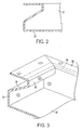
- a Panel Antenna 10 comprises an enclosure 12, internal cover 14, radome 16 and rear heat sinks 18.
- the enclosure 12 may be formed from sheet metal.
- the Panel Antenna 10 may include a plurality of micro radios 20 mounted within the enclosure 12.
- the micro radios 20 may be thermally coupled to the rear heat sinks 18.
- the internal cover 14 may include a plurality of RF modules 24.
- the enclosure 12 comprises a rear panel 30, a lower side wall 32, an angled side wall 34, an upper side wall 36, and a flange 38.
- lower side wall 32 and upper side wall 36 are perpendicular to rear panel 30 and flange 38 is parallel to the rear panel 30.
- Angled side wall 34 is angled toward the interior of the enclosure.
- the rear panel 30, side walls 32, 34, 36 and flange 38 may be formed from sheet metal. Corners, formed at the junctions of the walls may be welded. Welded corners have the benefit of preventing moisture from entering the enclosure via the corners.
- the combination of the rear panel 30, lower side wall 32, inclined side wall 34, upper side wall 36, and flange 38 may be configured such that these elements, when viewed in cross section, appear in a Z-shape.
- this Z-shape arrangement is employed on two longitudinal sides of the enclosure, and end walls 37 are flat.
- the Z-shape may be employed on three sides of the enclosure (e.g., two longitudinal sides and an end) or on all four sides of the enclosure.
- the Z-shape provides improved structural rigidity over conventional box-style structures.
- a Z-shaped sidewall enclosure provides enhanced internal space for a given outer flange dimension.
- the Z-shaped enclosure has more interior volume than a conventional box enclosure having an outward-turned flange of the same dimensions.
- An inward-turned flange may be used, however, such a flange may have additional challenges regarding sealing against adverse environmental conditions, especially moisture.
- an outward-turned flange is desirable because a radome may be configured to slide over and engage the outward-turned flanges, which allows installation and removal of a radome without installing or removing fasteners. This may be advantageous when servicing a Panel Antenna 10 located on a communications tower.
- Flange 38 may be flat and parallel to the rear panel 30.
- a flat flange 38 provides an area for facilitating a seal between flange 38 and inner cover 14.
- flange 38 includes sealing area 40.
- Flange 38 may also include a fastening system for the inner cover 14.
- the sealing area is located between the fastening system and a peripheral opening defined by upper side walls 36.
- locating the fasteners on the flange 38 outside the sealing area eliminates the need for the fasteners themselves to be sealed or to be of a sealable design.
- fasteners may be added after the sheet metal has been finished (e.g., painted, coated).
- the Panel Antenna 10 includes a communications hub 50, a power supply 52, and a calibration radio 54.
- interconnections between the communications hub, power supply, and calibration radio are protected from adverse environmental conditions by the enclosure 12, inner cover 14, and sealing area 40.
- each RF module 24 is coupled to a corresponding pair of micro radios 20.
- a first micro radio 20 of a pair of micro radios drives a first radiating element of the corresponding RF module 24, and a second micro radio 20 of the pair of micro radios drives a second radiating element of the corresponding RF module 24.
- This arrangement may be used, for example, where the RF modules 24 comprise dual polarized radiating elements.
- Each micro radio 20 is also connected to the communications hub 50.
- the communications hub 50 is connected to Base Station Equipment (BSE) (not illustrated).
- BSE Base Station Equipment
- a digital signal may be provided by the Base Station Equipment to the communications hub 50.
- a fiber optic link or other digital transmission medium may provide the connection between the BSE and the communications hub 50.
- the communications hub receives digital signals from the BSE, comprising information for RF transmission by the Panel Antenna 10, and transmits digital signals to the BSE, comprising information received by RF signal by the Panel Antenna 10.
- the connection between the communications hub 50 and each micro radio 20 may also be digital.
- the communications may comply with the SerDes standard.
- the communications hub 50 sends signals to the micro radios 20 for RF transmission, and receives signals from the micro radios 20 that correspond to RF signals received by the RF modules 24 and the micro radios 20.
- the communications hub 50 may also perform amplitude and phase adjustment to control attributes of RF transmission or reception. When amplitude and phase adjustment is performed electronically, a conventional feed network having electromechanical power dividers and phase shifters need not be included.
- a micro radio 20 may comprise a Digital Up Converter, a power Digital to Analog Converter (including a digital to RF converter).
- the micro radio may comprise a duplex radio, in which case it may also include a Time Division Duplex Switch, a Low Noise Analog to Digital Converter (including an RF to digital converter) and a Digital Down Converter.
- a Time Division Duplex Filter couples the Time Division Duplex Switch to a RF module.
- Internal cover 14 may be manufactured from a sheet of aluminum. Other materials may be used for internal cover 14. In the illustrated example, aluminum is selected because the material serves to provide both an environmental seal and an electromagnetic shield. In this example, internal cover 14 protects the micro radios 20 and other electronics in the Panel Antenna 10 from moisture and other environmental hazards, and shields the micro radios 20 and other electronics from the electromagnetic transmissions of the RF modules 24.
- the RF modules 24, as passive devices, need not be as effectively sealed from the elements as the active electronics.
- RF signals are carried between the RF modules 24 and micro radios 20 on cables (not shown). The cables may pass through sealed apertures in the inner seal 14.
- the internal cover 14 may also serve as a structural support for the RF modules 24.
- the RF modules may include a plurality of radio frequency radiating elements.
- the internal seal 14 supports eight RF modules 24.
- the RF modules 24 comprise patch antennas, and in particular, dual polarized patch antennas.
- the RF modules may comprise dipole or cross-dipole antenna elements.
- radiating elements may be disposed over a pan-shaped reflector. In other embodiments, radiating elements may be disposed over a ground plane.
- a patch radiator is positioned above a ground plane and excited such that a dual polarized RF signal is produced. This may be accomplished by exciting opposite sides of the radiator in antiphase.
- the internal seal 14 may be drilled to match the enclosure 12, so that mounting hardware may join the internal seal 14 to the enclosure 12.
- a seal 62 may be located over the studs in the aluminum frame. Alternatively, the seal may be located inside a periphery defined by the studs. Alternatively, two seals may be provided, a first seal over the studs, and a second seal inside a periphery defined by the studs.
- the radome 16 may include flanges (not illustrated) to engage and slide over edges defined by the flange of the enclosure 12, or the edges of the internal seal 14, or both.
- the radome 16 includes mounting apertures (not illustrated) through which fastening devices may pass.
- Panel Antenna 110 comprises an enclosure 112, radome assembly 116 and rear heat sinks 118.
- enclosure 112 is substantially the same as enclosure 12, the description of which is not repeated herein.
- Panel Antenna 110 may include a plurality of micro radios 120 mounted within the enclosure 112.
- the micro radios 120 may be grouped into radio modules 122.
- the radio modules 122 may be thermally coupled to the rear heat sinks 118.
- the radome assembly 116 includes a plurality of RF modules 124.
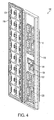
- a radome assembly 116 is illustrated.
- the radome assembly 116 includes a radome 160, a seal 162, and a plurality of RF modules 124.
- Each RF module 124 may include a plurality of RF elements.
- the RF elements may comprise individual modules, pairs or other groups of modules, or a plurality of RF elements in a single module.
- the Radome assembly of Fig. 5 includes eight RF modules.
- Each RF module 124 comprises one group of radiating elements.
- Each micro radio module 122 in this example includes two micro radios 120.
- the radio modules 122 are not limited to two micro radios, and may contain additional micro radios.
- Each micro radio 120 is connected to a corresponding RF module.
- Each micro radio 120 is also connected to the communications hub 150.
- the communications hub is connected to Base Station Equipment.
- a digital signal may be provided by the Base Station Equipment to the communications hub.
- a fiber optic link or other digital transmission medium may provide the connection.
- the connection between the communications hub and each micro radio may also be digital.
- the radome assembly 116 may include an aluminum frame 164 with studs 166.
- the reflecting elements of the RF modules 124 are integrated with the aluminum frame 164.
- the seal 162 may be located over the studs in the aluminum frame.
- the seal may be located inside a periphery defined by the studs.
- two seals may be provided, a first seal over the studs, and a second seal inside a periphery defined by the studs.
- the radome 160 includes mounting locations 168.
- the mounting locations 168 may comprise apertures through which fastening devices may pass.
- the RF modules 124 are located within the radome 160 with brackets 170 and screws 172, which pass through mounting locations 168. Alternatively, clips or bonding agents may be used to secure the RF modules 124 to radome 160. Providing mounting locations 168 in the radome 160 helps ensure accurate positioning of the RF elements in the radome 160.
- the RF modules 124 may be installed in the radome 160 to comprise the radome assembly 116.
- electronic components such as the micro radios 120, may be accessed without disturbing the location of the RF modules 124 in the radome 160.
- the RF modules 124 may be removed from the radome assembly 116 if service is required.
- the RF modules 124 may comprise patch antennas, and in particular, dual polarized patch antennas.
- the RF modules may comprise dipole or cross-dipole antenna elements.
- radiating elements may be disposed over a pan-shaped reflector. In other embodiments, radiating elements may be disposed over a ground plane.
Landscapes
- Engineering & Computer Science (AREA)
- Computer Networks & Wireless Communication (AREA)
- Details Of Aerials (AREA)
- Shielding Devices Or Components To Electric Or Magnetic Fields (AREA)
Claims (14)
- Eine Mobilfunk Basisstationsantenne (10), ein Gehäuse (12, 112), wobei das Gehäuse (12, 112) eine Rückenplatte (30), eine erste Seitenwand (32) und eine zweite Seitenwand (34), eine obere Wand (36) und eine Bodenwand einschließt, wobei die Rückenplatte (30) und die Wände einen Hohlraum bestimmen und die Wände weiter eine Öffnung bestimmen, durch welche auf den Hohlraum des Gehäuses (12) zugegriffen werden kann,
wobei mindestens eine aktive Funkkomponente (20) in dem Hohlraum montiert ist, und an die Rückenplatte (30), eine Wärmesenke (118) an einer äußeren Oberfläche der Rückenplatte (30) montiert ist, gekennzeichnet durch
eine interne Abdeckung (14), die an der Öffnung montiert ist, wobei die interne Abdeckung (14) dimensioniert ist, um einen Bereich zu überlappen, der durch die Öffnung des Gehäuses (12) bestimmt wird,
ein passives Funkgehäuse (116), das ein Radom (160) einschließt, wobei das passive Funkgehäuse (116) von dem Radom (160) und einer äußeren Oberfläche der internen Abdeckung (116) bestimmt wird und das Radom (160) verschiebbar in Flansche am Gehäuse (12) eingreift,
mindestens ein passives Funkelement (124), das in dem passiven Funkgehäuse (116) montiert ist, so dass auf die mindestens eine aktive Funkkomponente zugegriffen werden kann, ohne die Position des mindestens einen passiven Funkelements zu stören, das sich innerhalb des Radoms befindet, das daran gesichert ist, z. B. durch Klammern und Schrauben oder Klemmen oder Haftmittel, um sie für Servicezwecke leicht zu entfernen,
wobei das Gehäuse (12) und die interne Abdeckung (14) eine Umgebungsabdichtung und elektromagnetische Abschirmung für die aktive Funkkomponente (20) bereitstellen, und wobei das Radom (160) des passiven Funkgehäuses (116) keine Umgebungsabdichtung oder elektromagnetische Abschirmung für das passive Funkelement (124) bereitstellt. - Die Mobilfunk Basisstationsantenne (10) gemäß Anspruch 1, wobei die aktive Funkkomponente (20) weiter ein Mikrofunkmodul (120) umfasst und das passive Funkelement (124) ein HF-Modul (124) umfasst.
- Die Mobilfunk Basisstationsantenne (10) gemäß Anspruch 1, wobei die aktive Funkkomponente (20) weiter mindestens zwei Mikrofunkmodule umfasst und das passive Funkelement (124) ein doppelpolarisiertes HF-Modul umfasst, wobei ein erstes Mikrofunkmodul mit einem ersten Einzelstrahler des doppelpolarisierten HF-Moduls gekoppelt ist, und ein zweites Mikrofunkmodul mit einem zweiten Einzelstrahler des doppelpolarisierten HF-Moduls gekoppelt ist.
- Die Mobilfunk Basisstationsantenne (10) gemäß Anspruch 1, wobei die aktive Funkkomponente (20) weiter eine Vielzahl von Mikrofunkmodulen umfasst und das passive Funkelement (124) eine Vielzahl von HF-Modulen umfasst.
- Die Mobilfunk Basisstationsantenne (10) gemäß Anspruch 1, wobei die interne Abdeckung (14) aus einem Aluminiumblech hergestellt ist.
- Die Mobilfunk Basisstationsantenne (10) gemäß Anspruch 1, wobei die aktive Funkkomponente (20) weiter Folgendes umfasst:ein Mikrofunkmodul,einen Kommunikationsknoten (150), gekoppelt mit dem Mikrofunkmodul, undein Kalibrierfunkmodul.
- Die Mobilfunk Basisstationsantenne (10) gemäß Anspruch 1, wobei die passive Funkkomponente weiter eine Vielzahl von HF-Modulen umfasst, die an der äußeren Oberfläche der internen Abdeckung (14) montiert sind.
- Die Mobilfunk Basisstationsantenne (10) gemäß Anspruch 1, wobei ein Flansch die ersten und zweiten Seitenwände (32, 34) und die obere und die Bodenwand verbindet und eine Lippe sich vom Flansch erstreckt, die weiter die Öffnung bestimmt, durch welche auf den Hohlraum des Gehäuses zugegriffen werden kann, wobei die interne Abdeckung (116) in die Lippe eingreift, um die Umgebungsabdichtung bereitzustellen.
- Die Mobilfunk Basisstationsantenne (10) gemäß Anspruch 1, wobei die ersten Wände und die dritten Wände sich in rechten Winkeln zur Rückenplatte erstrecken.
- Die Mobilfunk Basisstationsantenne (10) gemäß Anspruch 1, wobei das Radom (160) verschiebbar in Flansche am Gehäuse (12) eingreift.
- Die Mobilfunk Basisstationsantenne (10) gemäß Anspruch 1, die weiter eine innere Abdichtung einschließt, welche für Umgebungs- und elektromagnetische Abschirmung sorgt.
- Die Mobilfunk Basisstationsantenne (10) gemäß Anspruch 1, wobei jeder Einzelstrahler mit zwei Mikrofunkmodulen verbunden ist.
- Die Mobilfunk Basisstationsantenne (10) gemäß Anspruch 1, die weiter einen Kommunikationsknoten umfasst, der mit jedem Mikrofunkmodul gekoppelt ist.
- Die Mobilfunk Basisstationsantenne (10) gemäß Anspruch 13, die weiter ein Kalibrierfunkmodul einschließt.
Applications Claiming Priority (2)
| Application Number | Priority Date | Filing Date | Title |
|---|---|---|---|
| US11911408P | 2008-12-02 | 2008-12-02 | |
| PCT/US2009/066345 WO2010065593A2 (en) | 2008-12-02 | 2009-12-02 | Panel antenna having sealed radio enclosure |
Publications (3)
| Publication Number | Publication Date |
|---|---|
| EP2364518A2 EP2364518A2 (de) | 2011-09-14 |
| EP2364518A4 EP2364518A4 (de) | 2012-08-15 |
| EP2364518B1 true EP2364518B1 (de) | 2016-03-09 |
Family
ID=42233835
Family Applications (1)
| Application Number | Title | Priority Date | Filing Date |
|---|---|---|---|
| EP09831021.2A Not-in-force EP2364518B1 (de) | 2008-12-02 | 2009-12-02 | Panelantelle mit versiegeltem funkgehäuse |
Country Status (4)
| Country | Link |
|---|---|
| EP (1) | EP2364518B1 (de) |
| CN (1) | CN102369635B (de) |
| BR (1) | BRPI0922725A2 (de) |
| WO (1) | WO2010065593A2 (de) |
Families Citing this family (10)
| Publication number | Priority date | Publication date | Assignee | Title |
|---|---|---|---|---|
| BR112012013364A8 (pt) * | 2009-12-02 | 2018-02-06 | Andrew Llc | Antena de painel que tem caixa vedada de rádio |
| CN103490175B (zh) * | 2013-09-23 | 2016-01-06 | 摩比天线技术(深圳)有限公司 | 一种一体化基站天线 |
| US9954568B1 (en) | 2014-06-25 | 2018-04-24 | Sprint Communications Company L.P. | Antenna module communication control in an antenna enclosure system |
| CA3009842C (en) * | 2015-12-29 | 2024-05-28 | Blue Danube Systems, Inc. | A low thermal impedance structure in a phased array |
| KR101769404B1 (ko) * | 2016-01-22 | 2017-08-21 | 주식회사 케이엠더블유 | 이동통신 네트워크의 안테나 일체형 기지국 장치 및 안테나 고정 장비 |
| CN105974371A (zh) * | 2016-06-21 | 2016-09-28 | 珠海纳睿达科技有限公司 | 相控阵气象雷达天线结构 |
| CN110521056B (zh) * | 2017-03-31 | 2021-08-03 | 株式会社Kmw | 天线组件及包括天线组件的装置 |
| EP3748374B8 (de) | 2019-06-06 | 2023-02-15 | Rohde & Schwarz GmbH & Co. KG | System und verfahren zur kalibrierung von funkfrequenz-testkammern |
| JP7417710B2 (ja) * | 2019-07-31 | 2024-01-18 | 華為技術有限公司 | 通信基地局 |
| CN115224535A (zh) * | 2021-04-15 | 2022-10-21 | 康普技术有限责任公司 | 连接装置和基站天线 |
Family Cites Families (7)
| Publication number | Priority date | Publication date | Assignee | Title |
|---|---|---|---|---|
| JP2001044734A (ja) * | 1999-07-26 | 2001-02-16 | Matsushita Electric Ind Co Ltd | 路側無線装置 |
| JP3594034B1 (ja) * | 2003-03-04 | 2004-11-24 | セイコーエプソン株式会社 | 電波修正時計 |
| JP3829839B2 (ja) * | 2003-11-14 | 2006-10-04 | 三菱電機株式会社 | 高周波パッケージ |
| EP1601046B1 (de) * | 2004-05-28 | 2008-07-02 | Huber + Suhner Ag | Gruppenantenne mit einem Antennengehäuse |
| GB0426319D0 (en) * | 2004-12-01 | 2005-01-05 | Finglas Technologies Ltd | Remote control of antenna line device |
| US7646355B2 (en) * | 2005-05-04 | 2010-01-12 | Sandwave Ip, Llc | Enclosure with ground plane |
| US8604981B2 (en) * | 2007-07-18 | 2013-12-10 | Times-7 Holdings Limited | Panel antenna and method of forming a panel antenna |
-
2009
- 2009-12-02 WO PCT/US2009/066345 patent/WO2010065593A2/en active Application Filing
- 2009-12-02 BR BRPI0922725A patent/BRPI0922725A2/pt not_active IP Right Cessation
- 2009-12-02 EP EP09831021.2A patent/EP2364518B1/de not_active Not-in-force
- 2009-12-02 CN CN2009801539416A patent/CN102369635B/zh active Active
Also Published As
| Publication number | Publication date |
|---|---|
| WO2010065593A2 (en) | 2010-06-10 |
| EP2364518A2 (de) | 2011-09-14 |
| CN102369635A (zh) | 2012-03-07 |
| BRPI0922725A2 (pt) | 2017-07-11 |
| CN102369635B (zh) | 2013-11-06 |
| WO2010065593A3 (en) | 2010-08-19 |
| EP2364518A4 (de) | 2012-08-15 |
Similar Documents
| Publication | Publication Date | Title |
|---|---|---|
| US8497813B2 (en) | Panel antenna having sealed radio enclosure | |
| EP2364518B1 (de) | Panelantelle mit versiegeltem funkgehäuse | |
| WO2017033573A1 (ja) | アンテナ装置 | |
| AU2010322590B2 (en) | Installation method of radiating elements disposed on different planes and antenna using same | |
| US6879291B2 (en) | Offsetting patch antennas on an ominidirectional multi-facetted array to allow space for an interconnection board | |
| KR20190086130A (ko) | 안테나 장치 | |
| US20230327327A1 (en) | Antenna apparatus | |
| WO2020149912A1 (en) | Active electronically scanned array (aesa) antenna configuration for simultaneous transmission and receiving of communication signals | |
| JP2023545468A (ja) | アンテナ用rfモジュール、rfモジュール組立体およびこれを含むアンテナ装置 | |
| JP2023546102A (ja) | アンテナ用rfモジュール、rfモジュール組立体およびこれを含むアンテナ装置 | |
| KR20230133252A (ko) | 안테나용 rf 모듈 및 이를 포함하는 안테나 장치 | |
| US12068766B2 (en) | Antenna filter and electronic device comprising same in wireless communication system | |
| CN101521546A (zh) | 智能天线的校准网络装置 | |
| KR20220097852A (ko) | 안테나용 rf 모듈 및 이를 포함하는 안테나 장치 | |
| JP2023546947A (ja) | アンテナ用rfモジュール、rfモジュール組立体およびこれを含むアンテナ装置 | |
| CN201188677Y (zh) | 智能天线的校准网络装置 | |
| KR102578367B1 (ko) | 안테나용 rf 모듈 및 이를 포함하는 안테나 장치 | |
| WO2023053864A1 (ja) | アンテナ装置及び通信装置 | |
| US20230395971A1 (en) | Passive/active base station antenna systems having passive reflector assemblies with an opening for an active antenna array | |
| CN116941131A (zh) | 天线射频模块及包括其的天线装置 | |
| KR102711676B1 (ko) | 안테나 장치 | |
| WO2013033894A1 (en) | Antenna assembly | |
| WO2024205828A2 (en) | Antennas with at least one pim shield and related devices | |
| CN219534861U (zh) | 天线射频模块及包括其的天线装置 | |
| CN217468809U (zh) | 用于有源天线单元的反射器组件和具有反射器组件的有源天线单元和基站天线 |
Legal Events
| Date | Code | Title | Description |
|---|---|---|---|
| PUAI | Public reference made under article 153(3) epc to a published international application that has entered the european phase |
Free format text: ORIGINAL CODE: 0009012 |
|
| 17P | Request for examination filed |
Effective date: 20110610 |
|
| AK | Designated contracting states |
Kind code of ref document: A2 Designated state(s): AT BE BG CH CY CZ DE DK EE ES FI FR GB GR HR HU IE IS IT LI LT LU LV MC MK MT NL NO PL PT RO SE SI SK SM TR |
|
| DAX | Request for extension of the european patent (deleted) | ||
| A4 | Supplementary search report drawn up and despatched |
Effective date: 20120712 |
|
| RIC1 | Information provided on ipc code assigned before grant |
Ipc: G01S 13/00 20060101ALI20120706BHEP Ipc: H01Q 9/04 20060101ALI20120706BHEP Ipc: H01Q 21/12 20060101AFI20120706BHEP Ipc: H01Q 19/10 20060101ALI20120706BHEP Ipc: H01Q 1/42 20060101ALI20120706BHEP Ipc: H01Q 1/24 20060101ALI20120706BHEP Ipc: H01Q 21/06 20060101ALI20120706BHEP Ipc: H04M 1/00 20060101ALI20120706BHEP |
|
| RAP1 | Party data changed (applicant data changed or rights of an application transferred) |
Owner name: COMMSCOPE TECHNOLOGIES LLC |
|
| 17Q | First examination report despatched |
Effective date: 20150424 |
|
| GRAP | Despatch of communication of intention to grant a patent |
Free format text: ORIGINAL CODE: EPIDOSNIGR1 |
|
| INTG | Intention to grant announced |
Effective date: 20150819 |
|
| GRAS | Grant fee paid |
Free format text: ORIGINAL CODE: EPIDOSNIGR3 |
|
| GRAA | (expected) grant |
Free format text: ORIGINAL CODE: 0009210 |
|
| AK | Designated contracting states |
Kind code of ref document: B1 Designated state(s): AT BE BG CH CY CZ DE DK EE ES FI FR GB GR HR HU IE IS IT LI LT LU LV MC MK MT NL NO PL PT RO SE SI SK SM TR |
|
| REG | Reference to a national code |
Ref country code: GB Ref legal event code: FG4D |
|
| REG | Reference to a national code |
Ref country code: AT Ref legal event code: REF Ref document number: 780105 Country of ref document: AT Kind code of ref document: T Effective date: 20160315 Ref country code: CH Ref legal event code: EP |
|
| REG | Reference to a national code |
Ref country code: IE Ref legal event code: FG4D |
|
| REG | Reference to a national code |
Ref country code: DE Ref legal event code: R096 Ref document number: 602009036721 Country of ref document: DE |
|
| REG | Reference to a national code |
Ref country code: LT Ref legal event code: MG4D |
|
| REG | Reference to a national code |
Ref country code: NL Ref legal event code: MP Effective date: 20160309 |
|
| PG25 | Lapsed in a contracting state [announced via postgrant information from national office to epo] |
Ref country code: NO Free format text: LAPSE BECAUSE OF FAILURE TO SUBMIT A TRANSLATION OF THE DESCRIPTION OR TO PAY THE FEE WITHIN THE PRESCRIBED TIME-LIMIT Effective date: 20160609 Ref country code: FI Free format text: LAPSE BECAUSE OF FAILURE TO SUBMIT A TRANSLATION OF THE DESCRIPTION OR TO PAY THE FEE WITHIN THE PRESCRIBED TIME-LIMIT Effective date: 20160309 Ref country code: ES Free format text: LAPSE BECAUSE OF FAILURE TO SUBMIT A TRANSLATION OF THE DESCRIPTION OR TO PAY THE FEE WITHIN THE PRESCRIBED TIME-LIMIT Effective date: 20160309 Ref country code: HR Free format text: LAPSE BECAUSE OF FAILURE TO SUBMIT A TRANSLATION OF THE DESCRIPTION OR TO PAY THE FEE WITHIN THE PRESCRIBED TIME-LIMIT Effective date: 20160309 Ref country code: GR Free format text: LAPSE BECAUSE OF FAILURE TO SUBMIT A TRANSLATION OF THE DESCRIPTION OR TO PAY THE FEE WITHIN THE PRESCRIBED TIME-LIMIT Effective date: 20160610 |
|
| REG | Reference to a national code |
Ref country code: AT Ref legal event code: MK05 Ref document number: 780105 Country of ref document: AT Kind code of ref document: T Effective date: 20160309 |
|
| PG25 | Lapsed in a contracting state [announced via postgrant information from national office to epo] |
Ref country code: SE Free format text: LAPSE BECAUSE OF FAILURE TO SUBMIT A TRANSLATION OF THE DESCRIPTION OR TO PAY THE FEE WITHIN THE PRESCRIBED TIME-LIMIT Effective date: 20160309 Ref country code: LT Free format text: LAPSE BECAUSE OF FAILURE TO SUBMIT A TRANSLATION OF THE DESCRIPTION OR TO PAY THE FEE WITHIN THE PRESCRIBED TIME-LIMIT Effective date: 20160309 Ref country code: PL Free format text: LAPSE BECAUSE OF FAILURE TO SUBMIT A TRANSLATION OF THE DESCRIPTION OR TO PAY THE FEE WITHIN THE PRESCRIBED TIME-LIMIT Effective date: 20160309 Ref country code: NL Free format text: LAPSE BECAUSE OF FAILURE TO SUBMIT A TRANSLATION OF THE DESCRIPTION OR TO PAY THE FEE WITHIN THE PRESCRIBED TIME-LIMIT Effective date: 20160309 Ref country code: LV Free format text: LAPSE BECAUSE OF FAILURE TO SUBMIT A TRANSLATION OF THE DESCRIPTION OR TO PAY THE FEE WITHIN THE PRESCRIBED TIME-LIMIT Effective date: 20160309 |
|
| PG25 | Lapsed in a contracting state [announced via postgrant information from national office to epo] |
Ref country code: EE Free format text: LAPSE BECAUSE OF FAILURE TO SUBMIT A TRANSLATION OF THE DESCRIPTION OR TO PAY THE FEE WITHIN THE PRESCRIBED TIME-LIMIT Effective date: 20160309 Ref country code: IS Free format text: LAPSE BECAUSE OF FAILURE TO SUBMIT A TRANSLATION OF THE DESCRIPTION OR TO PAY THE FEE WITHIN THE PRESCRIBED TIME-LIMIT Effective date: 20160709 |
|
| PG25 | Lapsed in a contracting state [announced via postgrant information from national office to epo] |
Ref country code: AT Free format text: LAPSE BECAUSE OF FAILURE TO SUBMIT A TRANSLATION OF THE DESCRIPTION OR TO PAY THE FEE WITHIN THE PRESCRIBED TIME-LIMIT Effective date: 20160309 Ref country code: CZ Free format text: LAPSE BECAUSE OF FAILURE TO SUBMIT A TRANSLATION OF THE DESCRIPTION OR TO PAY THE FEE WITHIN THE PRESCRIBED TIME-LIMIT Effective date: 20160309 Ref country code: PT Free format text: LAPSE BECAUSE OF FAILURE TO SUBMIT A TRANSLATION OF THE DESCRIPTION OR TO PAY THE FEE WITHIN THE PRESCRIBED TIME-LIMIT Effective date: 20160711 Ref country code: SK Free format text: LAPSE BECAUSE OF FAILURE TO SUBMIT A TRANSLATION OF THE DESCRIPTION OR TO PAY THE FEE WITHIN THE PRESCRIBED TIME-LIMIT Effective date: 20160309 Ref country code: RO Free format text: LAPSE BECAUSE OF FAILURE TO SUBMIT A TRANSLATION OF THE DESCRIPTION OR TO PAY THE FEE WITHIN THE PRESCRIBED TIME-LIMIT Effective date: 20160309 Ref country code: SM Free format text: LAPSE BECAUSE OF FAILURE TO SUBMIT A TRANSLATION OF THE DESCRIPTION OR TO PAY THE FEE WITHIN THE PRESCRIBED TIME-LIMIT Effective date: 20160309 |
|
| REG | Reference to a national code |
Ref country code: DE Ref legal event code: R097 Ref document number: 602009036721 Country of ref document: DE |
|
| REG | Reference to a national code |
Ref country code: FR Ref legal event code: PLFP Year of fee payment: 8 |
|
| PG25 | Lapsed in a contracting state [announced via postgrant information from national office to epo] |
Ref country code: BE Free format text: LAPSE BECAUSE OF FAILURE TO SUBMIT A TRANSLATION OF THE DESCRIPTION OR TO PAY THE FEE WITHIN THE PRESCRIBED TIME-LIMIT Effective date: 20160309 Ref country code: IT Free format text: LAPSE BECAUSE OF FAILURE TO SUBMIT A TRANSLATION OF THE DESCRIPTION OR TO PAY THE FEE WITHIN THE PRESCRIBED TIME-LIMIT Effective date: 20160309 |
|
| PLBE | No opposition filed within time limit |
Free format text: ORIGINAL CODE: 0009261 |
|
| STAA | Information on the status of an ep patent application or granted ep patent |
Free format text: STATUS: NO OPPOSITION FILED WITHIN TIME LIMIT |
|
| PG25 | Lapsed in a contracting state [announced via postgrant information from national office to epo] |
Ref country code: DK Free format text: LAPSE BECAUSE OF FAILURE TO SUBMIT A TRANSLATION OF THE DESCRIPTION OR TO PAY THE FEE WITHIN THE PRESCRIBED TIME-LIMIT Effective date: 20160309 |
|
| 26N | No opposition filed |
Effective date: 20161212 |
|
| PG25 | Lapsed in a contracting state [announced via postgrant information from national office to epo] |
Ref country code: BG Free format text: LAPSE BECAUSE OF FAILURE TO SUBMIT A TRANSLATION OF THE DESCRIPTION OR TO PAY THE FEE WITHIN THE PRESCRIBED TIME-LIMIT Effective date: 20160609 |
|
| PG25 | Lapsed in a contracting state [announced via postgrant information from national office to epo] |
Ref country code: SI Free format text: LAPSE BECAUSE OF FAILURE TO SUBMIT A TRANSLATION OF THE DESCRIPTION OR TO PAY THE FEE WITHIN THE PRESCRIBED TIME-LIMIT Effective date: 20160309 |
|
| REG | Reference to a national code |
Ref country code: CH Ref legal event code: PL |
|
| PG25 | Lapsed in a contracting state [announced via postgrant information from national office to epo] |
Ref country code: MC Free format text: LAPSE BECAUSE OF FAILURE TO SUBMIT A TRANSLATION OF THE DESCRIPTION OR TO PAY THE FEE WITHIN THE PRESCRIBED TIME-LIMIT Effective date: 20160309 |
|
| REG | Reference to a national code |
Ref country code: IE Ref legal event code: MM4A |
|
| PG25 | Lapsed in a contracting state [announced via postgrant information from national office to epo] |
Ref country code: LU Free format text: LAPSE BECAUSE OF NON-PAYMENT OF DUE FEES Effective date: 20161202 Ref country code: CH Free format text: LAPSE BECAUSE OF NON-PAYMENT OF DUE FEES Effective date: 20161231 Ref country code: LI Free format text: LAPSE BECAUSE OF NON-PAYMENT OF DUE FEES Effective date: 20161231 |
|
| PG25 | Lapsed in a contracting state [announced via postgrant information from national office to epo] |
Ref country code: IE Free format text: LAPSE BECAUSE OF NON-PAYMENT OF DUE FEES Effective date: 20161202 |
|
| REG | Reference to a national code |
Ref country code: FR Ref legal event code: PLFP Year of fee payment: 9 |
|
| PG25 | Lapsed in a contracting state [announced via postgrant information from national office to epo] |
Ref country code: CY Free format text: LAPSE BECAUSE OF FAILURE TO SUBMIT A TRANSLATION OF THE DESCRIPTION OR TO PAY THE FEE WITHIN THE PRESCRIBED TIME-LIMIT Effective date: 20160309 Ref country code: HU Free format text: LAPSE BECAUSE OF FAILURE TO SUBMIT A TRANSLATION OF THE DESCRIPTION OR TO PAY THE FEE WITHIN THE PRESCRIBED TIME-LIMIT; INVALID AB INITIO Effective date: 20091202 |
|
| PG25 | Lapsed in a contracting state [announced via postgrant information from national office to epo] |
Ref country code: TR Free format text: LAPSE BECAUSE OF FAILURE TO SUBMIT A TRANSLATION OF THE DESCRIPTION OR TO PAY THE FEE WITHIN THE PRESCRIBED TIME-LIMIT Effective date: 20160309 Ref country code: MK Free format text: LAPSE BECAUSE OF FAILURE TO SUBMIT A TRANSLATION OF THE DESCRIPTION OR TO PAY THE FEE WITHIN THE PRESCRIBED TIME-LIMIT Effective date: 20160309 |
|
| PG25 | Lapsed in a contracting state [announced via postgrant information from national office to epo] |
Ref country code: MT Free format text: LAPSE BECAUSE OF NON-PAYMENT OF DUE FEES Effective date: 20161202 |
|
| PGFP | Annual fee paid to national office [announced via postgrant information from national office to epo] |
Ref country code: GB Payment date: 20181227 Year of fee payment: 10 Ref country code: FR Payment date: 20181226 Year of fee payment: 10 |
|
| PGFP | Annual fee paid to national office [announced via postgrant information from national office to epo] |
Ref country code: DE Payment date: 20181231 Year of fee payment: 10 |
|
| REG | Reference to a national code |
Ref country code: DE Ref legal event code: R119 Ref document number: 602009036721 Country of ref document: DE |
|
| GBPC | Gb: european patent ceased through non-payment of renewal fee |
Effective date: 20191202 |
|
| PG25 | Lapsed in a contracting state [announced via postgrant information from national office to epo] |
Ref country code: DE Free format text: LAPSE BECAUSE OF NON-PAYMENT OF DUE FEES Effective date: 20200701 Ref country code: GB Free format text: LAPSE BECAUSE OF NON-PAYMENT OF DUE FEES Effective date: 20191202 Ref country code: FR Free format text: LAPSE BECAUSE OF NON-PAYMENT OF DUE FEES Effective date: 20191231 |