EP2363948B1 - Procédé de détermination de la fréquence statorique de champ électromagnétique et/ou du sens de rotation du champ magnétique d'une machine synchrone ou asynchrone ainsi que dispositif correspondant et machine synchrone ou asynchrone - Google Patents
Procédé de détermination de la fréquence statorique de champ électromagnétique et/ou du sens de rotation du champ magnétique d'une machine synchrone ou asynchrone ainsi que dispositif correspondant et machine synchrone ou asynchrone Download PDFInfo
- Publication number
- EP2363948B1 EP2363948B1 EP20100155176 EP10155176A EP2363948B1 EP 2363948 B1 EP2363948 B1 EP 2363948B1 EP 20100155176 EP20100155176 EP 20100155176 EP 10155176 A EP10155176 A EP 10155176A EP 2363948 B1 EP2363948 B1 EP 2363948B1
- Authority
- EP
- European Patent Office
- Prior art keywords
- rotating field
- voltage space
- stator rotating
- space indicator
- synchronous
- Prior art date
- Legal status (The legal status is an assumption and is not a legal conclusion. Google has not performed a legal analysis and makes no representation as to the accuracy of the status listed.)
- Active
Links
- 238000000034 method Methods 0.000 title claims description 37
- 230000001360 synchronised effect Effects 0.000 title claims description 34
- 230000015572 biosynthetic process Effects 0.000 claims description 17
- 239000004065 semiconductor Substances 0.000 claims description 15
- 230000005684 electric field Effects 0.000 claims description 4
- 239000013598 vector Substances 0.000 description 22
- 238000011156 evaluation Methods 0.000 description 18
- 230000004913 activation Effects 0.000 description 6
- 238000004804 winding Methods 0.000 description 6
- 238000010586 diagram Methods 0.000 description 3
- 238000005259 measurement Methods 0.000 description 3
- 230000003213 activating effect Effects 0.000 description 2
- 238000013459 approach Methods 0.000 description 2
- 238000012937 correction Methods 0.000 description 2
- 238000001514 detection method Methods 0.000 description 2
- 238000003745 diagnosis Methods 0.000 description 2
- 238000012544 monitoring process Methods 0.000 description 2
- 230000001550 time effect Effects 0.000 description 2
- 230000006399 behavior Effects 0.000 description 1
- 238000006243 chemical reaction Methods 0.000 description 1
- 238000009795 derivation Methods 0.000 description 1
- 238000011161 development Methods 0.000 description 1
- 230000000694 effects Effects 0.000 description 1
- 238000000605 extraction Methods 0.000 description 1
- 238000011089 mechanical engineering Methods 0.000 description 1
- 238000004806 packaging method and process Methods 0.000 description 1
- 230000000737 periodic effect Effects 0.000 description 1
- 238000005096 rolling process Methods 0.000 description 1
- 238000012360 testing method Methods 0.000 description 1
- 239000004753 textile Substances 0.000 description 1
- 230000001052 transient effect Effects 0.000 description 1
- 238000011144 upstream manufacturing Methods 0.000 description 1
Images


Classifications
-
- H—ELECTRICITY
- H02—GENERATION; CONVERSION OR DISTRIBUTION OF ELECTRIC POWER
- H02P—CONTROL OR REGULATION OF ELECTRIC MOTORS, ELECTRIC GENERATORS OR DYNAMO-ELECTRIC CONVERTERS; CONTROLLING TRANSFORMERS, REACTORS OR CHOKE COILS
- H02P27/00—Arrangements or methods for the control of AC motors characterised by the kind of supply voltage
- H02P27/04—Arrangements or methods for the control of AC motors characterised by the kind of supply voltage using variable-frequency supply voltage, e.g. inverter or converter supply voltage
- H02P27/06—Arrangements or methods for the control of AC motors characterised by the kind of supply voltage using variable-frequency supply voltage, e.g. inverter or converter supply voltage using dc to ac converters or inverters
- H02P27/08—Arrangements or methods for the control of AC motors characterised by the kind of supply voltage using variable-frequency supply voltage, e.g. inverter or converter supply voltage using dc to ac converters or inverters with pulse width modulation
- H02P27/12—Arrangements or methods for the control of AC motors characterised by the kind of supply voltage using variable-frequency supply voltage, e.g. inverter or converter supply voltage using dc to ac converters or inverters with pulse width modulation pulsing by guiding the flux vector, current vector or voltage vector on a circle or a closed curve, e.g. for direct torque control
Definitions
- the invention relates to a method for determining the electric stator rotating field frequency and / or the direction of rotation of the stator rotating field of a synchronous or asynchronous machine, which is controlled by means of a drive switching device with at least one switching element. Furthermore, the invention relates to a device which is designed to determine the electrical stator rotational field frequency and / or the direction of rotation of the stator rotating field of a synchronous or asynchronous machine, wherein the synchronous or asynchronous machine can be controlled by means of a Anêtschalt planted with at least one switching element, and a corresponding synchronous or asynchronous machine.
- a method and a device for detecting the motor position of an electric motor are known.
- the motor according to this document is connected to a drive circuit which has a number of switch arrangements corresponding to the number of motor windings, each having at least one switch and one output terminal.
- the switches of the switch arrangements conduct or disable in accordance with drive signals that assume a first level or a second level.
- the motor position is detected by evaluating the potentials at the terminals of the motor, wherein the potentials at the terminals of the motor are evaluated only during predetermined periods of time whose timing and duration derived from the control signals. In this document, therefore, it is about the potentials at the motor terminals in a suitable manner limited to certain times to measure and evaluate.
- the US 7,126,301 B2 relates to a motor drive having a plurality of transistors serving as switches to power motor windings. Furthermore, a position detector is provided to detect, based on the terminal voltage of the respective winding, the rotational position of the rotor of the motor. This type of position detection thus requires a detector DE 195 30 622 calculates the stator frequency of a rotary field machine exclusively by means of the Austuersignale the inverter, with their switching periods are determined.
- the invention has for its object to provide a comparison with the prior art improved method of the type mentioned above and a corresponding device or synchronous or asynchronous machine.
- the determination or determination of the rotating field frequency as possible takes place at the end of the chain of effects.
- the proposed solution according to the invention in which only these control signals are used for the determination of the rotational frequency or direction of rotation of the stator rotating field itself does not require a sensor or detector and can accordingly, if desired, be used for plausibility of donors.
- Other signals than the drive pulses for the switching elements which may be, for example, semiconductor switching elements are not required.
- rotational frequency of the stator rotating field and the direction of rotation statements may be made regarding the actual rotational speed or direction of rotation of a rotating field machine, if necessary.
- the exclusive consideration according to the invention of the drive signals of the switching elements for the drive switching device is particularly recommended for strategies for plausibility check, condition monitoring or diagnosis in connection with the operation of synchronous or asynchronous machines.
- Typical drive switching devices have, for example, six switching elements. They can be designed as a pulse inverter with six switching elements.
- the method can be used in various applications in mechanical engineering, such as in rolling mill, in the printing, packaging and textile industry, robotics in the field of general motion, etc.
- the control signals for the one or more switching elements can be generated by a control electronics and / or evaluated or determined using a model having at least one voltage space vector and / or at least one resulting nominal voltage space vector.
- the Heidelbergelementan Kunststoffsignale can be generated by a control electronics, which is connected upstream of the switching elements of the or the An Kunststoffschalt issued.
- the control electronics may be part of the An Kunststoffschalt issued.
- the determination or evaluation of the drive signals, for example, the semiconductor switching element control signals for frequency or direction of rotation for the stator rotating field can by using at least one voltage space vector or from a resulting, for the sectors of the voltage space representation defined Statorpan Vietnamesesraum artern resulting resultant Sollthesesraum art (in this sense Total voltage space pointer forms).
- control signals for example, for the semiconductor switches can thus be derived in a development of the invention from the Sollhardsraum adapter or based on this pointer and / or a corresponding space vector representation and / or determine.
- space vector / space vector displays for example, the already mentioned thesis by Dr.-Ing. H. Zatocil.
- the voltage space pointer (s) and / or the resulting setpoint voltage space pointer or the associated voltage space pointer representation can be determined within the scope of a current regulation and / or a voltage / frequency control (U / f control).
- the Sollwoodsraum Attacher are thus for example a result of a for the system Machine performed or implemented for this flow control, but can also be generated in other ways.
- a semiconductor switching element can be used, or it can only be used as switching elements of the Anberichtschalt raised semiconductor switching elements, in particular bipolar transistors with insulated gate electrode (so-called insulated gate bipolar transistors, IGBTs).
- IGBTs insulated gate bipolar transistors
- the electric stator rotary field frequency or the direction of rotation of the stator rotary field is determined according to the invention solely on the basis of the drive signals of the IGBTs.
- the drive signals of the IGBTs then result, as already described, from the setpoint voltage space pointers, which in turn are based on current regulation or voltage-frequency control (U / f control) or otherwise generated.
- IGBTs IGBTs
- other semiconductor switching elements or different semiconductor switching elements can also be used in combination in a drive switching device.
- the type of evaluation of the control signals of these semiconductor switching elements or the different switching elements of the Anbericht timber would then possibly be suitably adapted to continue to determine the rotational field frequency or direction of rotation of the stator rotating field and on this basis, where appropriate, the machine continue to reliably.
- one or at least one inverter can be used, in particular a three-phase inverter and / or a pulse inverter and / or an inverter with bipolar transistors with insulated gate electrode and associated freewheeling diodes and / or a two-point inverter and / or one of a DC intermediate circuit powered and / or a three-phase load driving inverter.
- the method for determining the rotating field frequency or direction of rotation of the stator rotating field of a Anberichtschalt founded which is formed by a three-phase inverter with six IGBTs and six free-wheeling diodes, which are each associated with the IGBTs.
- This circuit can be powered by a DC voltage intermediate circuit.
- Connected to the inverter is a three-phase load, ie a three-phase asynchronous or synchronous machine.
- the period to or the stator rotational field frequency is determined by means of a switching line which separates areas in a nominal voltage space pointer representation in which one of two opposite by 180 degrees (pointing in different directions 180) voltage space pointers to form a resulting target voltage space pointer is active.
- the switching line is thus drawn so that it marks the onset of participation each one of the two pointers to the formation of the total pointer.
- two sectors lying next to one another can be, on the one hand, the two contiguous sectors I and VI, in which the pointer 1 participates in the formation of the nominal voltage space vector, and, on the other hand, the two sectors III and IV, which are likewise adjacent to one another and in which the pointer 4 is involved in the formation of tension.
- a switching line can be defined, which separates the two areas in which on the one hand, the first pointer, on the other hand, the second pointer become active.
- the switching line thus runs on the border between sectors V and VI on the one hand (in sector VI the participation of the first pointer 1 starts) and sectors II and III on the other hand (in sector III the pointer 4 becomes active).
- the boundary between the sectors V and VI stands for the activation of the pointer 1 for voltage formation, the boundary between the sectors II and III for the activation of the pointer 4. Whether the respective pointers 1 or 4 or other pairs of 180 degrees are opposite lying voltage space pointers are involved in the formation of voltage can be queried on the basis of the switching states of the IGBTs.
- a memory can be set, which is reset when the participation of the voltage space vector counterclockwise by 180 degrees commences.
- memory is set whenever pointer 1 becomes active, and when pointer 4 subsequently becomes active, that memory is reset.
- the involvement of the two opposing voltage space vector in the formation of the resulting Sollstructsraumze can be determined by means of the switching states of the switching elements of the An Kunststoffschalt gifted, in particular the two-step inverter, the conditions for setting and resetting the memory are determined logic-based.
- the conditions for setting and resetting are thus formed by a logic or their presence or absence is determined by a logic circuit, wherein the immediate evaluation of the switching signals through & -Gate (AND gate) can be represented or done.
- a characteristic periodic signal curve which follows from the exceeding of the switching lines by the nominal voltage space vector U *.
- the period T 1 which results from the consideration of the switching line, corresponds to the period of the stator rotational field frequency.
- the direction of rotation of the stator rotating field can be determined, in particular in the case of a two-point inverter with six sectors in the nominal voltage space as An Kunststoffschalt raised by means of at least one, in particular at least one other, switching line in Sollstructsraum, in particular by means of another switching line, compared to a switching line for determining the period of the stator rotating field shifted by 60 degrees or 120 degrees.
- the period duration for stator rotary field frequency determined by the consideration of a switching line in the Sollstructsraum adapterdar ein it must then be used to detect the direction of rotation of the stator rotating field, a second signal and evaluated.
- a second signal For this purpose, for example, if the pointers 1 and 4 were initially turned off to determine the period, the pointers 2 and 5 are used, pointer 2 representing the sectors I and II from each other and pointer 5, the sectors IV and V.
- the associated switching line is rotated by 60 degrees with respect to the first switching line.
- a corresponding rectangular time signal or binary signal, derived analogously to the procedure previously described for hands 1 and 4 would be shifted in phase by 60 degrees with respect to the signal used to determine the period duration.
- the derivation or evaluation of this second signal can be carried out as previously described on the basis of the participation or the activation of the respective pointer. Again, setting and resetting a memory can be logic-based.
- the stator rotational field frequency of the electric field can, in particular in the case of a two-level inverter with six sectors in a Sollstructsraum acknowledgeerdar ein as An Kunststoffalt founded by counting the edges of the resulting by the exceeding of a switching line by the resulting nominal voltage space vector square signals or Binary signals within a fixed time interval and / or by time measurement between two edges of the resulting by the exceeding of a switching line by the resulting nominal voltage space pointer resulting square / binary signals are determined.
- a locking time implemented in the drive switching device in particular the drive logic corresponding butterhablleiter, be taken into account.
- an interlocking time implemented in the inverter (s) constitutes a dead time in the system that should be considered.
- the locking time ensures that in a branch, for example, a pulse inverter as a drive switching device never both semiconductor switches, for example, both transistors are turned on at the same time and thus are in a conductive state.
- the locking time implemented in the drive logic of the power semiconductors leads to switching patterns occurring during the detection of the drive signals which can not be detected by the described logic circuit. Typical lock times may be a few microseconds ( ⁇ s), for example four microseconds.
- the measured value of the drive signal would only assume the state HIGH after the end of the dead time, so that the sequence for rotating field frequency determination would be disturbed.
- the described reconstruction the pulse pattern which would be valid in the case without locking, thus serves exclusively to carry out the method according to the invention or the stator rotational field frequency determination or -wartichtung determination.
- the thus reconstructed pulse pattern signals must not be output via the driver to the power unit. For the real system, the additional security created by the implementation of dead times should be preserved.
- the electric stator rotary field frequency and / or the direction of rotation of the stator rotating field of the synchronous or asynchronous machine can be determined in the stationary state and / or for checking and / or plausibility of the signals of at least one sensor and / or encoder element.
- the method described is primarily suitable for the operation or the frequency and / or direction of rotation of the stator rotating field of the drive in the stationary state, less for transient processes.
- the method according to the invention can serve to make the measured values of the sensors plausible. It is a sensorless method for Drehfeldfrequenzá or -wartichtun that can be used in different contexts, for example, for the purpose of condition monitoring or diagnosis.
- the invention relates to a device which is designed to determine the electric stator rotational field frequency and / or the direction of rotation of the stator rotating field of a synchronous or asynchronous machine, wherein the synchronous or asynchronous machine by means of a Anberichtschalt raised with at least one switching element is controlled, in particular a device which for determining the electrical stator rotational field frequency and / or the direction of rotation of the stator rotary field in accordance with a method as described above, the device being characterized by the features of claim 13.
- the stator rotary field frequency or stator rotating field rotational direction determining device may be a separate component or a separate component (both in terms of hardware and in terms of software). But it is also conceivable that the device is integrated in a An Griffinschalt raised or control electronics or one or more existing components of the machine control or connected to them. The device accordingly has evaluation means, for example a logic circuit.
- the evaluation means can serve the binary signals or square-wave signals resulting from the exceeding of one or more switching lines in a nominal voltage space vector display, for example a representation with six sectors in the case of a two-level inverter, for determining the period duration for the stator rotary field frequency (ie the period duration) corresponds to the inverse of the stator rotary field frequency and in this sense corresponds to the stator rotary field frequency), to evaluate the direction of rotation or the frequency of the stator rotary field.
- a nominal voltage space vector display for example a representation with six sectors in the case of a two-level inverter
- the invention relates to a synchronous or asynchronous machine, which is characterized in that it is associated with a device for determining the electric stator rotational field frequency or direction of rotation as described above.
- This device may be a part of the machine or, as already described, the drive switching device or control electronics.
- a synchronous or asynchronous machine there is the possibility of determining the rotational frequency of the stator rotating field or of its direction of rotation alone starting from the drive signals for the IGBTs or the drive signals for other switching elements of the drive switching device of the synchronous or asynchronous machine.
- FIG. 1 a block diagram of a drive switching device in the form of a pulse inverter
- FIG. 2 a representation of the voltage space pointer and sectors for a two-point inverter, in particular according to FIG. 1 .
- FIG. 3 a table of each sector of the FIG. 2 used voltage space pointer
- FIG. 4 a table of the switching states of the IGBTs of FIG. 1 for the active pointers 1 to 6 and the so-called null pointers 7 and 8 according to FIG FIG. 2 .
- FIG. 5 a representation for the involvement of the voltage space pointers 1 and 4 on the formation of the nominal voltage space vector
- FIG. 6 a representation of the logic-based evaluation of the drive signals for the IGBTs according to FIG. 1 in the context of the method according to the invention
- FIG. 7 a representation of the resulting from exceeding the switching line to the pointers 1 and 4 by the resulting target voltage space vector U * driving waveform
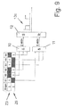
- FIGS. 8 and 9 Representations of the logic-based evaluation of the control signals in the case of query on the one hand the hands 2 and 5, on the other hand, the hands 3 and 6,
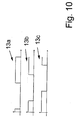
- FIG. 10 a representation of the three according to FIG. 6 . 8th and 9 determined phase-shifted binary drive signals and
- FIG. 11 a representation to be considered in the context of the invention locking time.
- FIG. 1 is a block diagram of a drive switching device 1 shown in the form of a pulse inverter.
- the drive switching device 1 in the form of a three-phase inverter with six (semiconductor) switching elements 2a-2f, here the IGBTs 2a-2f, serves to drive a three-phase load in the form of an asynchronous or synchronous machine 3.
- the drive switching device 1 is connected to the motor windings 4a, 4b, 4c, where i U , i v and i w denote the respective currents and U, V and W denote the voltages at the terminals of the synchronous or asynchronous machine 3, respectively.
- the voltages to be assigned to the windings 4a, 4b, 4c are variable with respect to time and are designated in the present illustration by u U , u v and u w .
- the drive switching device 1 has an associated freewheeling diode 5a-5f (D1 to D6) for each of the IGBTs 2a-2f (S1 to S6).
- the drive switching device 1 receives signals of a control electronics 6 and is fed by a DC voltage intermediate circuit 7.
- the voltage of the intermediate circuit 7 is designated by U ZK .
- only the drive signals for the IGBTs 2a-2f are used in order to determine the stator rotary field frequency or direction of rotation of the stator rotary field of the synchronous or asynchronous machine 3 exclusively on the basis of these drive signals.
- FIG. 2 to illustrate a procedure according to the invention is a representation of the voltage space pointers 1, 2, 3 , ..., 7 and 8 (here with the reference numerals Z1, Z2, Z3, Z4, Z5, Z6, Z7, Z8) and the associated sectors I - VI (here with the reference numerals 8a, 8b, 8c, 8d, 8e, 8f) for a two-point inverter, for example according to FIG. 1 .
- the axes ⁇ and ⁇ denote the axes of the stator or stator coordinate system.
- the spatial axes a, b and c are shown.
- the magnitude of the voltage space vector 2 corresponds to 2/3 of the amount of intermediate circuit voltage, U ZK . This also applies to the other active hands 1 , 2 , 3 , ..., 6 .
- FIG. 3 is a table of each sector I to VI of the FIG. 2 used voltage space vector 1 to 8 shown.
- the pointers 1 to 6 represent the so-called active hands, while the hands 7 and 8 form the so-called null pointers.
- the space vectors 1, 2 , 7 , 8 (Z1, Z2, Z7, Z8) are assigned to the sector I (8a)
- the pointers 2 , 3 , 7 and 8 are assigned to the sector II (8b).
- the FIG. 4 shows a table of the switching states of the IGBTs of FIG. 1 for the active pointers 1 to 6 (Z1 to Z6) and the so-called null pointers 7 and 8 (Z7 and Z8).
- S1, S2 to S6 are the IGBTs 2a, 2b to 2f of FIG. 1 designated.
- the switching state of all IGBTs S1-S6 is shown in binary form, with the values 0 and 1, respectively.
- FIG. 5 1 is an illustration of the involvement of the voltage space pointers 1 (Z1) and 4 (Z4) in the formation of the resulting target voltage space vector.
- the pointer Z4 is involved in the formation of the voltage, in the two sectors 8a and 8f (1 or VI) the pointer Z1.
- These sector areas are in the FIG. 5 shown darker.
- the respective switching states of the IGBTs 2a to 2f (S1-S6) assigned to the pointers Z1 and Z4 are also shown in FIG FIG. 5 reproduced (bottom left and top right).
- a memory is set.
- this memory is reset.
- the setting and resetting of the memory defines a switching line 9, which separates the areas in the nominal voltage space representation, in which one of the 180 degrees opposite voltage space pointer Z1 ( 1 ) and Z4 ( 4 ) to form the resulting nominal voltage space pointer is active (ie the area in which the memory is set, from the area where the memory is not set).
- a stator frequency of f 1 becomes constant as in the FIG. 5 shown, reset or reset every 180 degrees of memory.
- FIG. 6 shows a representation of the logic-based evaluation of the drive signals in the context of the method according to the invention, wherein in the upper left in the illustration of FIG. 6 the switching states of the IGBTs 2a to 2f (S1 to S6) are shown for the pointers Z1 ( 1 ) and Z4 ( 4 ).
- the conditions for setting and resetting the memory are formed by logic, wherein the immediate evaluation of the switching signals by the two & -gate 10 (for the determination Z1 active) and 11 (for Z4 active) is made.
- box 12 a setting (S) and resetting (R) of the memory are then carried out in each case.
- the resulting waveform is denoted by reference numeral 13a. It is a binary signal or a signal with a rectangular shape.
- FIG. 7 shows a more extensive representation of the resulting from the exceeding of the switching line 9 by the resulting target voltage space pointer 14 ( U *) resulting drive waveform 13a.
- the pointer Z4 ( 4 ) becomes active, the memory is reset. The signal level or the signal amount in the signal curve 13a drops to zero on reaching the corresponding time coordinate 15a on the time axis.
- the memory is set again because the pointer Z1 ( 1 ) becomes active. The signal rises at this point in the signal curve 13a, which is assigned to the time coordinate 15b, to a positive value or an amount not equal to 0.
- the period T 1 can be derived, which corresponds to the reciprocal of the frequency f 1 .
- the period T 1 for the stator rotating field is shown here as the duration between the first falling of the signal to the time coordinates 15 b and the second, falling back of the signal to the time coordinates 15 c.
- FIGS. 8 and 9 are representations of the logic-based evaluation of the control signals when interrogating the pointers Z2 ( 2 ) and Z5 ( 5 ) ( FIG. 8 ) and the pointers Z3 ( 3 ) and Z6 ( 6 ) ( FIG. 9 ).
- signal curves 13b, 13c can additionally be obtained if the direction of rotation of the St Sfeldes to be determined in addition to the period.
- these other pairs of pointers can also be considered as an alternative to the pointer pair Z1, Z4.
- FIG. 8 and 9 are representations of the logic-based evaluation of the control signals when interrogating the pointers Z2 ( 2 ) and Z5 ( 5 ) ( FIG. 8 ) and the pointers Z3 ( 3 ) and Z6 ( 6 ) ( FIG. 9 ).
- FIG. 10 is a common representation of the three according to the FIGS. 6 . 8th and 9 determined phase-shifted binary drive signals 13a, 13b, 13c.
- two different approaches are available. On the one hand, it is possible to count the edges of the three generated square wave signals or signal curves 13a, 13b and 13c within a fixed time interval. On the other hand, it is possible to perform a time measurement between two edges of the three generated square wave signals of the waveforms 13a, 13b and 13c corresponding to 60 electrical degrees. The first variant is to be preferred at higher speeds of the machine, the second at lower speeds. If all three signal curves 13a, 13b and 13c or the correspondingly generated binary signals are taken into account, information is available every 60 degrees. With a restriction to only one of these signals, only every 180 degrees would receive information. The use of all three signal curves 13a, 13b and 13c thus leads to a tripling of the resolution.
- FIG. 11 shows a representation of the locking time to be considered in the invention, wherein for the IGBTs S1 to S6 in each case the switching states (0 or 1) are plotted against the time t in microseconds.
- the illustration refers to a speed of 30 revolutions per minute (min -1 ) and a DC link frequency U ZK of 565 volts.
- lock times are implemented, which represent dead times of the system.
- the time coordinates of the first on / off operations of the IGBTs 2a to 2f in the diagram are designated by 16a to 16f.
- Sense of locking times is to ensure that in a branch of the pulse inverter according to the FIG. 1 never both IGBTs are switched on at the same time and are therefore in a conducting state.
- the IGBT 2b (S2) in FIG. 1 and 11 the IGBT 2a (S1) is not switched on immediately (at the time 16b), but only with a delay, for example after expiration of a locking time of a few microseconds, at the time 16a.
- the lock-in time is four microseconds. Accordingly, after switching off S1, the IGBT S2 is not switched on again until four microseconds later.
- Analog lock times are provided for the IGBT pairs in the other branches.
Claims (14)
- Procédé de détermination de la fréquence statorique de champ électromagnétique et/ou du sens de rotation du champ magnétique d'une machine synchrone ou asynchrone (3) qui est commandée à l'aide d'un dispositif de commande (1) comportant au moins un élément de commutation (2a - 2f), dans lequel la fréquence statorique de champ électromagnétique et/ou le sens de rotation du champ magnétique sont déterminés exclusivement à l'aide des signaux de commande desdits un ou plusieurs éléments de commutation (2a - 2f) du dispositif de commande (1), caractérisé en ce que, dans le cadre de la détermination de la fréquence statorique de champ électromagnétique et/ou du sens de rotation du champ magnétique de la machine synchrone ou asynchrone (3), la durée de période de la fréquence statorique de champ électromagnétique est déterminée à l'aide d'une droite de commutation (9) dont le tracé, dans une représentation de vecteurs spatiaux de tension de consigne, indique que respectivement l'un de deux vecteurs spatiaux de tension (Z1 et Z4 ; Z2 et Z5 ; Z3 et Z6) opposés de 180°C devient actif pour former un vecteur spatial de tension de consigne (14) résultant, et dans lequel respectivement au début de la participation de l'un des vecteurs spatiaux de tension (Z1- Z3) à la formation du vecteur spatial de tension de consigne (14) résultant est activée (S) une mémoire, laquelle est réinitialisée (R) lorsque débute la participation du vecteur spatial de tension (Z4 - Z6) opposé de 180°.
- Procédé selon la revendication 1, caractérisé en ce que les signaux de commande desdits un ou plusieurs éléments de commutation (2a - 2f) sont générés par une électronique' de commande (6) et/ou évalués en utilisant un modèle ou une représentation comportant au moins un vecteur spatial de tension (Z1 - Z8) et/ou au moins un vecteur spatial de tension de consigne (14) résultant.
- Procédé selon la revendication 2, caractérisé en ce que le ou les vecteurs spatiaux de tension (Z1 - Z8) et/ou le vecteur spatial de tension de consigne (14) résultant sont déterminés dans le cadre d'une régulation de courant et/ou d'une commande de tension/fréquence.
- Procédé selon l'une des revendications précédentes, caractérisé en ce qu'on utilise en tant qu'au moins un élément de commutation (2a - 2f) du dispositif de commande (1) un élément de commutation à semi-conducteur (2a - 2f) ou en ce qu'on utilise comme éléments de commutation (2a - 2f) du dispositif de commande (1) exclusivement des éléments de commutation à semi-conducteur (2a - 2f), en particulier des transistors bipolaires à électrode de grille isolée (IGBTs, 2a - 2f).
- Procédé selon l'une des revendications précédentes, caractérisé en ce qu'on utilise comme dispositif de commande (1) au moins un onduleur, en particulier un onduleur triphasé et/ou un onduleur à impulsions et/ou un onduleur à transistors bipolaires à électrode de grille isolée (2a - 2f) et à diodes de roue libre (5a - 5f) associées respectivement et/ou un onduleur à deux niveaux et/ou un onduleur alimenté par un circuit intermédiaire à tension continue (7) et/ou un onduleur entraînant une charge triphasée.
- Procédé selon l'une des revendications précédentes, caractérisé en ce qu'il est réalisé dans le cas d'un onduleur à deux niveaux comportant six secteurs (8a - 8f) dans la représentation de vecteurs spatiaux de tension de consigne en tant que dispositif de commande (1).
- Procédé selon l'une des revendications précédentes, caractérisé en ce que la participation des deux vecteurs spatiaux de tension opposés (Z1 et Z4 ; Z2 et Z5 ; Z3 et Z6) à la formation du vecteur spatial de tension de consigne (14) résultant est déterminée à l'aide des états de commutation des éléments de commutation (2a - 2f) du dispositif de commande (1), en particulier de l'onduleur à deux niveaux, la détermination des conditions d'activation (S) et de réinitialisation (R) de la mémoire étant basée sur la logique.
- Procédé selon l'une des revendications précédentes, caractérisé en ce que le sens de rotation du champ magnétique, en particulier dans le cas d'un onduleur à deux niveaux comportant six secteurs (8a - 8f) dans une représentation de vecteurs spatiaux de tension de consigne en tant que dispositif de commande (1), est déterminé à l'aide d'au moins une, en particulier au moins une autre droite de commutation dans la représentation de vecteurs spatiaux de tension de consigne, en particulier à l' aide d'une autre droite de commutation qui est décalée de 60° ou 120° par rapport à une droite de commutation (9) destinée à la détermination de la durée de période de la fréquence statorique de champ électromagnétique.
- Procédé selon l'une des revendications précédentes, caractérisé en ce que la fréquence statorique du champ électromagnétique, en particulier dans le cas d'un onduleur à deux niveaux comportant six secteurs (8a - 8f) dans une représentation de vecteurs spatiaux de tension de consigne en tant que dispositif de commande (1), est déterminée par comptage des fronts des signaux rectangulaires ou binaires (13a, 13b, 13c) résultant du dépassement d'une droite de commutation par le vecteur spatial de tension de consigne résultant à l'intérieur d'un intervalle de temps fixe, et/ou par mesure du temps entre deux fronts des signaux rectangulaires ou binaires (13a, 13b, 13c) résultant du dépassement d'une droite de commutation par le vecteur spatial de tension de consigne résultant.
- Procédé selon l'une des revendications 6 à 10, caractérisé en ce que, dans le cas d'un onduleur à deux niveaux comportant six secteurs (8a - 8f) dans une représentation de vecteurs spatiaux de tension de consigne en tant que dispositif de commande (1), on utilise les trois signaux rectangulaires ou binaires résultant du dépassement d'une droite de commutation respective par le vecteur spatial de tension de consigne résultant pour déterminer la fréquence statorique de champ électromagnétique.
- Procédé selon l'une des revendications précédentes, caractérisé en ce que, dans le cadre du procédé de détermination de la fréquence statorique de champ électromagnétique et/ou du sens de rotation du champ magnétique d'une machine synchrone ou asynchrone (3), on prend en compte un temps de verrouillage implémenté dans le dispositif de commande (1).
- Procédé selon l'une des revendications précédentes, caractérisé en ce que la fréquence statorique de champ électromagnétique et/ou le sens de rotation du champ magnétique d'une machine synchrone ou asynchrone (3) est déterminé(e) à l'état stationnaire et/ou pour vérification et/ou plausibilisation des signaux d'au moins un élément détecteur et/ou capteur.
- Dispositif conçu pour déterminer la fréquence statorique de champ électromagnétique et/ou le sens de rotation du champ magnétique d'une machine synchrone ou asynchrone (3), dans lequel la machine synchrone ou asynchrone (3) peut être commandée à l'aide d'un dispositif de commande (1) comprenant au moins un élément de commutation (2a - 2f), en particulier dispositif conçu pour déterminer la fréquence statorique de champ électromagnétique et/ou le sens de rotation du champ magnétique selon un procédé selon l'une des revendications précédentes, caractérisé en ce que le dispositif est réalisé pour déterminer la fréquence statorique de champ électromagnétique et/ou le sens de rotation du champ magnétique exclusivement à l'aide des signaux de commande desdits un ou plusieurs éléments de commutation (2a - 2f) du dispositif de commande (1) délivrés par une électronique de commande (6), de façon telle que, dans le cadre de la détermination de la fréquence statorique de champ électromagnétique et/ou du sens de rotation du champ magnétique de la machine synchrone ou asynchrone (3), la durée de période de la fréquence statorique de champ électromagnétique est déterminée à l'aide d'une droite de commutation (9) dont le tracé, dans une représentation de vecteurs spatiaux de tension de consigne, indique que respectivement l'un de deux vecteurs spatiaux de tension (Z1 et Z4 ; Z2 et Z5 ; Z3 et Z6) opposés de 180°C devient actif pour former un vecteur spatial de tension de consigne (14) résultant, et en ce que respectivement au début de la participation de l'un des vecteurs spatiaux de tension (Z1 - Z3) à la formation du vecteur spatial de tension de consigne (14) résultant est activée (S) une mémoire, laquelle est réinitialisée (R) lorsque débute la participation du vecteur spatial de tension (Z4 - Z6) opposé de 180°.
- Machine synchrone ou asynchrone (3), caractérisée en ce qu'à la machine synchrone ou asynchrone (3) est associé un dispositif selon la revendication 13.
Priority Applications (1)
| Application Number | Priority Date | Filing Date | Title |
|---|---|---|---|
| EP20100155176 EP2363948B1 (fr) | 2010-03-02 | 2010-03-02 | Procédé de détermination de la fréquence statorique de champ électromagnétique et/ou du sens de rotation du champ magnétique d'une machine synchrone ou asynchrone ainsi que dispositif correspondant et machine synchrone ou asynchrone |
Applications Claiming Priority (1)
| Application Number | Priority Date | Filing Date | Title |
|---|---|---|---|
| EP20100155176 EP2363948B1 (fr) | 2010-03-02 | 2010-03-02 | Procédé de détermination de la fréquence statorique de champ électromagnétique et/ou du sens de rotation du champ magnétique d'une machine synchrone ou asynchrone ainsi que dispositif correspondant et machine synchrone ou asynchrone |
Publications (2)
| Publication Number | Publication Date |
|---|---|
| EP2363948A1 EP2363948A1 (fr) | 2011-09-07 |
| EP2363948B1 true EP2363948B1 (fr) | 2014-12-03 |
Family
ID=42542803
Family Applications (1)
| Application Number | Title | Priority Date | Filing Date |
|---|---|---|---|
| EP20100155176 Active EP2363948B1 (fr) | 2010-03-02 | 2010-03-02 | Procédé de détermination de la fréquence statorique de champ électromagnétique et/ou du sens de rotation du champ magnétique d'une machine synchrone ou asynchrone ainsi que dispositif correspondant et machine synchrone ou asynchrone |
Country Status (1)
| Country | Link |
|---|---|
| EP (1) | EP2363948B1 (fr) |
Families Citing this family (1)
| Publication number | Priority date | Publication date | Assignee | Title |
|---|---|---|---|---|
| CN104300561A (zh) * | 2014-09-30 | 2015-01-21 | 华北电力大学(保定) | 一种用于vsc-hvdc系统的三相四桥臂换流器的控制方法 |
Family Cites Families (7)
| Publication number | Priority date | Publication date | Assignee | Title |
|---|---|---|---|---|
| DE19530622A1 (de) * | 1995-08-21 | 1996-10-10 | Abb Daimler Benz Transp | Verfahren zur Drehmomentregelung einer Drehfeldmaschine |
| DE19612988A1 (de) * | 1996-03-22 | 1997-09-25 | Abb Daimler Benz Transp | Verfahren zur Bestimmung der Lage des Flußraumzeigers im ständerfesten Koordinatensystem für die Ermittlung der Schaltzustände eines Pulswechselrichters |
| US6069808A (en) * | 1997-05-21 | 2000-05-30 | Texas Instruments Incorporated | Symmetrical space vector PWM DC-AC converter controller |
| AU2002213229A1 (en) * | 2000-10-13 | 2002-04-22 | Solectria Corporation | Improved distribution of space-vector pwm conduction losses |
| DE10207338A1 (de) | 2002-02-21 | 2003-09-11 | Infineon Technologies Ag | Verfahren und Vorrichtung zur Erfassung der Motorposition eines Elektromotors |
| US7126301B2 (en) | 2002-10-22 | 2006-10-24 | Matsushita Electric Industrial Co., Ltd. | Motor driver |
| JP4288614B2 (ja) * | 2006-05-19 | 2009-07-01 | 日新電機株式会社 | 電圧形三相インバータの制御方法及び制御装置 |
-
2010
- 2010-03-02 EP EP20100155176 patent/EP2363948B1/fr active Active
Also Published As
| Publication number | Publication date |
|---|---|
| EP2363948A1 (fr) | 2011-09-07 |
Similar Documents
| Publication | Publication Date | Title |
|---|---|---|
| DE102007054050B4 (de) | Halbleiter-Leistungsumsetzer | |
| DE112010001309B4 (de) | Antriebssteuerungsvorrichtung für einen Elektromotor | |
| DE10243602A1 (de) | Leistungsumrichter, der zum Minimieren von Schaltungsverlusten entworfen ist | |
| DE112017003161B4 (de) | Stromrichtervorrichtung und Logikschaltung | |
| EP2875579B1 (fr) | Procédé de détermination de la position du rotor d'un moteur à courant continu multiphasé à commutation électronique | |
| DE102013109624A1 (de) | Regelvorrichtung für Permanentmagnet-Synchronmotor, die eine irreversible Entmagnetisierung des Permanentmagneten verhindert und Regelsystem dafür | |
| DE102016200241A1 (de) | Steuervorrichtung für eine drehende elektrische maschine | |
| EP2843828B1 (fr) | Procédé et dispositif pour déterminer la position d'une roue polaire d'une machine électrique commutée électroniquement | |
| DE102010061933A1 (de) | Verfahren zum Nachweis eines Kabelbruchs eines Motors | |
| DE102014109513A1 (de) | Verfahren und Vorrichtung zum Überwachen eines elektrischen Kraftstromkreises | |
| EP2026461B1 (fr) | Procédé de régulation sans capteur d'un moteur à courant triphasé | |
| WO2012103993A1 (fr) | Procédé et dispositif d'étalonnage d'au moins un capteur de courant | |
| EP3017536B1 (fr) | Procédé et dispositif de détermination, sans l'aide de capteur, d'une position d'un rotor d'une machine électrique | |
| WO2011157472A1 (fr) | Montage pour déterminer une variation de tension de potentiels de conducteur dans un réseau électrique non mis à la terre | |
| DE102016224178A1 (de) | Steuerung einer sechsphasigen PSM | |
| EP2363948B1 (fr) | Procédé de détermination de la fréquence statorique de champ électromagnétique et/ou du sens de rotation du champ magnétique d'une machine synchrone ou asynchrone ainsi que dispositif correspondant et machine synchrone ou asynchrone | |
| DE102010033459A1 (de) | Verfahren zur Fehlererkennung bei der Ansteuerung eines Drehfeldmotors | |
| EP3619805B1 (fr) | Procédé et dispositif de détermination de l'angle de position d'un rotor d'une machine synchrone électrique | |
| DE102012110271B4 (de) | Vorrichtung und Verfahren zum Bremsen eines Elektromotors | |
| DE102013222007A1 (de) | Prozessor, Vorrichtung, Verfahren und Computerprogramm zum Steuern eines Notfallbetriebs einer mehrphasigen Drehfeldmaschine bei Unterbrechung eines ersten Phasenstroms einer ersten Phase der Drehfeldmaschine | |
| WO2011157470A1 (fr) | Montage pour déterminer une variation de tension de potentiels de conducteur dans un réseau électrique non mis à la terre | |
| EP2777144B1 (fr) | Procédé d'étalonnage d'un onduleur multiphasé, dispositif pour faire fonctionner un programme d'ordinateur et produit de programme d'ordinateur | |
| DE102016204854A1 (de) | Ermittlung eines Kurzschlussstroms in den Phasen einer mittels eines Wechselrichters angesteuerten E-Maschine | |
| EP3857704A1 (fr) | Procédé pour déterminer une valeur de correction décrivant une différence angulaire entre une position supposée et une position réelle un axe d, unité de commande et onduleur | |
| DE102017211219A1 (de) | Verfahren und Vorrichtung zum Betreiben einer elektrischen Maschine, insbesondere eines Lenkunterstützungsantriebs |
Legal Events
| Date | Code | Title | Description |
|---|---|---|---|
| PUAI | Public reference made under article 153(3) epc to a published international application that has entered the european phase |
Free format text: ORIGINAL CODE: 0009012 |
|
| AK | Designated contracting states |
Kind code of ref document: A1 Designated state(s): AT BE BG CH CY CZ DE DK EE ES FI FR GB GR HR HU IE IS IT LI LT LU LV MC MK MT NL NO PL PT RO SE SI SK SM TR |
|
| AX | Request for extension of the european patent |
Extension state: AL BA ME RS |
|
| RIN1 | Information on inventor provided before grant (corrected) |
Inventor name: VILLWOCK, SEBASTIAN Inventor name: ZATOCIL, HEIKO |
|
| 17P | Request for examination filed |
Effective date: 20120621 |
|
| 17Q | First examination report despatched |
Effective date: 20131128 |
|
| REG | Reference to a national code |
Ref country code: DE Ref legal event code: R079 Ref document number: 502010008383 Country of ref document: DE Free format text: PREVIOUS MAIN CLASS: H02M0007538700 Ipc: H02P0027080000 |
|
| RIC1 | Information provided on ipc code assigned before grant |
Ipc: H02M 7/5387 20070101ALI20140512BHEP Ipc: H02P 27/12 20060101ALI20140512BHEP Ipc: H02P 27/08 20060101AFI20140512BHEP |
|
| GRAP | Despatch of communication of intention to grant a patent |
Free format text: ORIGINAL CODE: EPIDOSNIGR1 |
|
| INTG | Intention to grant announced |
Effective date: 20140626 |
|
| GRAS | Grant fee paid |
Free format text: ORIGINAL CODE: EPIDOSNIGR3 |
|
| GRAA | (expected) grant |
Free format text: ORIGINAL CODE: 0009210 |
|
| AK | Designated contracting states |
Kind code of ref document: B1 Designated state(s): AT BE BG CH CY CZ DE DK EE ES FI FR GB GR HR HU IE IS IT LI LT LU LV MC MK MT NL NO PL PT RO SE SI SK SM TR |
|
| REG | Reference to a national code |
Ref country code: GB Ref legal event code: FG4D Free format text: NOT ENGLISH |
|
| REG | Reference to a national code |
Ref country code: AT Ref legal event code: REF Ref document number: 699875 Country of ref document: AT Kind code of ref document: T Effective date: 20141215 Ref country code: CH Ref legal event code: EP |
|
| REG | Reference to a national code |
Ref country code: IE Ref legal event code: FG4D Free format text: LANGUAGE OF EP DOCUMENT: GERMAN |
|
| REG | Reference to a national code |
Ref country code: DE Ref legal event code: R096 Ref document number: 502010008383 Country of ref document: DE Effective date: 20150115 Ref country code: CH Ref legal event code: NV Representative=s name: SCHNEIDER FELDMANN AG PATENT- UND MARKENANWAEL, CH |
|
| REG | Reference to a national code |
Ref country code: NL Ref legal event code: T3 |
|
| PG25 | Lapsed in a contracting state [announced via postgrant information from national office to epo] |
Ref country code: ES Free format text: LAPSE BECAUSE OF FAILURE TO SUBMIT A TRANSLATION OF THE DESCRIPTION OR TO PAY THE FEE WITHIN THE PRESCRIBED TIME-LIMIT Effective date: 20141203 Ref country code: FI Free format text: LAPSE BECAUSE OF FAILURE TO SUBMIT A TRANSLATION OF THE DESCRIPTION OR TO PAY THE FEE WITHIN THE PRESCRIBED TIME-LIMIT Effective date: 20141203 Ref country code: NO Free format text: LAPSE BECAUSE OF FAILURE TO SUBMIT A TRANSLATION OF THE DESCRIPTION OR TO PAY THE FEE WITHIN THE PRESCRIBED TIME-LIMIT Effective date: 20150303 Ref country code: LT Free format text: LAPSE BECAUSE OF FAILURE TO SUBMIT A TRANSLATION OF THE DESCRIPTION OR TO PAY THE FEE WITHIN THE PRESCRIBED TIME-LIMIT Effective date: 20141203 |
|
| REG | Reference to a national code |
Ref country code: LT Ref legal event code: MG4D |
|
| PG25 | Lapsed in a contracting state [announced via postgrant information from national office to epo] |
Ref country code: SE Free format text: LAPSE BECAUSE OF FAILURE TO SUBMIT A TRANSLATION OF THE DESCRIPTION OR TO PAY THE FEE WITHIN THE PRESCRIBED TIME-LIMIT Effective date: 20141203 Ref country code: LV Free format text: LAPSE BECAUSE OF FAILURE TO SUBMIT A TRANSLATION OF THE DESCRIPTION OR TO PAY THE FEE WITHIN THE PRESCRIBED TIME-LIMIT Effective date: 20141203 Ref country code: HR Free format text: LAPSE BECAUSE OF FAILURE TO SUBMIT A TRANSLATION OF THE DESCRIPTION OR TO PAY THE FEE WITHIN THE PRESCRIBED TIME-LIMIT Effective date: 20141203 Ref country code: GR Free format text: LAPSE BECAUSE OF FAILURE TO SUBMIT A TRANSLATION OF THE DESCRIPTION OR TO PAY THE FEE WITHIN THE PRESCRIBED TIME-LIMIT Effective date: 20150304 Ref country code: CY Free format text: LAPSE BECAUSE OF FAILURE TO SUBMIT A TRANSLATION OF THE DESCRIPTION OR TO PAY THE FEE WITHIN THE PRESCRIBED TIME-LIMIT Effective date: 20141203 |
|
| PG25 | Lapsed in a contracting state [announced via postgrant information from national office to epo] |
Ref country code: SK Free format text: LAPSE BECAUSE OF FAILURE TO SUBMIT A TRANSLATION OF THE DESCRIPTION OR TO PAY THE FEE WITHIN THE PRESCRIBED TIME-LIMIT Effective date: 20141203 Ref country code: EE Free format text: LAPSE BECAUSE OF FAILURE TO SUBMIT A TRANSLATION OF THE DESCRIPTION OR TO PAY THE FEE WITHIN THE PRESCRIBED TIME-LIMIT Effective date: 20141203 Ref country code: PT Free format text: LAPSE BECAUSE OF FAILURE TO SUBMIT A TRANSLATION OF THE DESCRIPTION OR TO PAY THE FEE WITHIN THE PRESCRIBED TIME-LIMIT Effective date: 20150403 Ref country code: RO Free format text: LAPSE BECAUSE OF FAILURE TO SUBMIT A TRANSLATION OF THE DESCRIPTION OR TO PAY THE FEE WITHIN THE PRESCRIBED TIME-LIMIT Effective date: 20141203 Ref country code: CZ Free format text: LAPSE BECAUSE OF FAILURE TO SUBMIT A TRANSLATION OF THE DESCRIPTION OR TO PAY THE FEE WITHIN THE PRESCRIBED TIME-LIMIT Effective date: 20141203 |
|
| PG25 | Lapsed in a contracting state [announced via postgrant information from national office to epo] |
Ref country code: IS Free format text: LAPSE BECAUSE OF FAILURE TO SUBMIT A TRANSLATION OF THE DESCRIPTION OR TO PAY THE FEE WITHIN THE PRESCRIBED TIME-LIMIT Effective date: 20150403 Ref country code: PL Free format text: LAPSE BECAUSE OF FAILURE TO SUBMIT A TRANSLATION OF THE DESCRIPTION OR TO PAY THE FEE WITHIN THE PRESCRIBED TIME-LIMIT Effective date: 20141203 |
|
| REG | Reference to a national code |
Ref country code: DE Ref legal event code: R097 Ref document number: 502010008383 Country of ref document: DE |
|
| PLBE | No opposition filed within time limit |
Free format text: ORIGINAL CODE: 0009261 |
|
| STAA | Information on the status of an ep patent application or granted ep patent |
Free format text: STATUS: NO OPPOSITION FILED WITHIN TIME LIMIT |
|
| PG25 | Lapsed in a contracting state [announced via postgrant information from national office to epo] |
Ref country code: DK Free format text: LAPSE BECAUSE OF FAILURE TO SUBMIT A TRANSLATION OF THE DESCRIPTION OR TO PAY THE FEE WITHIN THE PRESCRIBED TIME-LIMIT Effective date: 20141203 Ref country code: MC Free format text: LAPSE BECAUSE OF FAILURE TO SUBMIT A TRANSLATION OF THE DESCRIPTION OR TO PAY THE FEE WITHIN THE PRESCRIBED TIME-LIMIT Effective date: 20141203 Ref country code: LU Free format text: LAPSE BECAUSE OF FAILURE TO SUBMIT A TRANSLATION OF THE DESCRIPTION OR TO PAY THE FEE WITHIN THE PRESCRIBED TIME-LIMIT Effective date: 20150302 |
|
| 26N | No opposition filed |
Effective date: 20150904 |
|
| REG | Reference to a national code |
Ref country code: IE Ref legal event code: MM4A |
|
| PG25 | Lapsed in a contracting state [announced via postgrant information from national office to epo] |
Ref country code: IE Free format text: LAPSE BECAUSE OF NON-PAYMENT OF DUE FEES Effective date: 20150302 |
|
| PG25 | Lapsed in a contracting state [announced via postgrant information from national office to epo] |
Ref country code: SI Free format text: LAPSE BECAUSE OF FAILURE TO SUBMIT A TRANSLATION OF THE DESCRIPTION OR TO PAY THE FEE WITHIN THE PRESCRIBED TIME-LIMIT Effective date: 20141203 |
|
| REG | Reference to a national code |
Ref country code: FR Ref legal event code: PLFP Year of fee payment: 7 |
|
| PG25 | Lapsed in a contracting state [announced via postgrant information from national office to epo] |
Ref country code: MT Free format text: LAPSE BECAUSE OF FAILURE TO SUBMIT A TRANSLATION OF THE DESCRIPTION OR TO PAY THE FEE WITHIN THE PRESCRIBED TIME-LIMIT Effective date: 20141203 |
|
| REG | Reference to a national code |
Ref country code: FR Ref legal event code: PLFP Year of fee payment: 8 |
|
| PG25 | Lapsed in a contracting state [announced via postgrant information from national office to epo] |
Ref country code: SM Free format text: LAPSE BECAUSE OF FAILURE TO SUBMIT A TRANSLATION OF THE DESCRIPTION OR TO PAY THE FEE WITHIN THE PRESCRIBED TIME-LIMIT Effective date: 20141203 Ref country code: BG Free format text: LAPSE BECAUSE OF FAILURE TO SUBMIT A TRANSLATION OF THE DESCRIPTION OR TO PAY THE FEE WITHIN THE PRESCRIBED TIME-LIMIT Effective date: 20141203 Ref country code: HU Free format text: LAPSE BECAUSE OF FAILURE TO SUBMIT A TRANSLATION OF THE DESCRIPTION OR TO PAY THE FEE WITHIN THE PRESCRIBED TIME-LIMIT; INVALID AB INITIO Effective date: 20100302 |
|
| PG25 | Lapsed in a contracting state [announced via postgrant information from national office to epo] |
Ref country code: BE Free format text: LAPSE BECAUSE OF NON-PAYMENT OF DUE FEES Effective date: 20150331 |
|
| PG25 | Lapsed in a contracting state [announced via postgrant information from national office to epo] |
Ref country code: TR Free format text: LAPSE BECAUSE OF FAILURE TO SUBMIT A TRANSLATION OF THE DESCRIPTION OR TO PAY THE FEE WITHIN THE PRESCRIBED TIME-LIMIT Effective date: 20141203 |
|
| REG | Reference to a national code |
Ref country code: FR Ref legal event code: PLFP Year of fee payment: 9 |
|
| PG25 | Lapsed in a contracting state [announced via postgrant information from national office to epo] |
Ref country code: MK Free format text: LAPSE BECAUSE OF FAILURE TO SUBMIT A TRANSLATION OF THE DESCRIPTION OR TO PAY THE FEE WITHIN THE PRESCRIBED TIME-LIMIT Effective date: 20141203 |
|
| REG | Reference to a national code |
Ref country code: CH Ref legal event code: PFA Owner name: BAUMUELLER NUERNBERG GMBH, DE Free format text: FORMER OWNER: BAUMUELLER NUERNBERG GMBH, DE |
|
| PGFP | Annual fee paid to national office [announced via postgrant information from national office to epo] |
Ref country code: NL Payment date: 20220322 Year of fee payment: 13 |
|
| PGFP | Annual fee paid to national office [announced via postgrant information from national office to epo] |
Ref country code: FR Payment date: 20230320 Year of fee payment: 14 Ref country code: AT Payment date: 20230317 Year of fee payment: 14 |
|
| PGFP | Annual fee paid to national office [announced via postgrant information from national office to epo] |
Ref country code: GB Payment date: 20230323 Year of fee payment: 14 |
|
| PGFP | Annual fee paid to national office [announced via postgrant information from national office to epo] |
Ref country code: IT Payment date: 20230331 Year of fee payment: 14 Ref country code: CH Payment date: 20230402 Year of fee payment: 14 |
|
| REG | Reference to a national code |
Ref country code: NL Ref legal event code: MM Effective date: 20230401 |
|
| PG25 | Lapsed in a contracting state [announced via postgrant information from national office to epo] |
Ref country code: NL Free format text: LAPSE BECAUSE OF NON-PAYMENT OF DUE FEES Effective date: 20230401 |
|
| PGFP | Annual fee paid to national office [announced via postgrant information from national office to epo] |
Ref country code: DE Payment date: 20240321 Year of fee payment: 15 |