EP2363948B1 - Method for determining the electric stator rotating field frequency and/or the rotation direction of the stator rotating field frequency of a synchronous or asynchronous machine and corresponding device and synchronous or asynchronous machine. - Google Patents
Method for determining the electric stator rotating field frequency and/or the rotation direction of the stator rotating field frequency of a synchronous or asynchronous machine and corresponding device and synchronous or asynchronous machine. Download PDFInfo
- Publication number
- EP2363948B1 EP2363948B1 EP20100155176 EP10155176A EP2363948B1 EP 2363948 B1 EP2363948 B1 EP 2363948B1 EP 20100155176 EP20100155176 EP 20100155176 EP 10155176 A EP10155176 A EP 10155176A EP 2363948 B1 EP2363948 B1 EP 2363948B1
- Authority
- EP
- European Patent Office
- Prior art keywords
- rotating field
- voltage space
- stator rotating
- space indicator
- synchronous
- Prior art date
- Legal status (The legal status is an assumption and is not a legal conclusion. Google has not performed a legal analysis and makes no representation as to the accuracy of the status listed.)
- Active
Links
- 238000000034 method Methods 0.000 title claims description 37
- 230000001360 synchronised effect Effects 0.000 title claims description 34
- 230000015572 biosynthetic process Effects 0.000 claims description 17
- 239000004065 semiconductor Substances 0.000 claims description 15
- 230000005684 electric field Effects 0.000 claims description 4
- 239000013598 vector Substances 0.000 description 22
- 238000011156 evaluation Methods 0.000 description 18
- 230000004913 activation Effects 0.000 description 6
- 238000004804 winding Methods 0.000 description 6
- 238000010586 diagram Methods 0.000 description 3
- 238000005259 measurement Methods 0.000 description 3
- 230000003213 activating effect Effects 0.000 description 2
- 238000013459 approach Methods 0.000 description 2
- 238000012937 correction Methods 0.000 description 2
- 238000001514 detection method Methods 0.000 description 2
- 238000003745 diagnosis Methods 0.000 description 2
- 238000012544 monitoring process Methods 0.000 description 2
- 230000001550 time effect Effects 0.000 description 2
- 230000006399 behavior Effects 0.000 description 1
- 238000006243 chemical reaction Methods 0.000 description 1
- 238000009795 derivation Methods 0.000 description 1
- 238000011161 development Methods 0.000 description 1
- 230000000694 effects Effects 0.000 description 1
- 238000000605 extraction Methods 0.000 description 1
- 238000011089 mechanical engineering Methods 0.000 description 1
- 238000004806 packaging method and process Methods 0.000 description 1
- 230000000737 periodic effect Effects 0.000 description 1
- 238000005096 rolling process Methods 0.000 description 1
- 238000012360 testing method Methods 0.000 description 1
- 239000004753 textile Substances 0.000 description 1
- 230000001052 transient effect Effects 0.000 description 1
- 238000011144 upstream manufacturing Methods 0.000 description 1
Images


Classifications
-
- H—ELECTRICITY
- H02—GENERATION; CONVERSION OR DISTRIBUTION OF ELECTRIC POWER
- H02P—CONTROL OR REGULATION OF ELECTRIC MOTORS, ELECTRIC GENERATORS OR DYNAMO-ELECTRIC CONVERTERS; CONTROLLING TRANSFORMERS, REACTORS OR CHOKE COILS
- H02P27/00—Arrangements or methods for the control of AC motors characterised by the kind of supply voltage
- H02P27/04—Arrangements or methods for the control of AC motors characterised by the kind of supply voltage using variable-frequency supply voltage, e.g. inverter or converter supply voltage
- H02P27/06—Arrangements or methods for the control of AC motors characterised by the kind of supply voltage using variable-frequency supply voltage, e.g. inverter or converter supply voltage using dc to ac converters or inverters
- H02P27/08—Arrangements or methods for the control of AC motors characterised by the kind of supply voltage using variable-frequency supply voltage, e.g. inverter or converter supply voltage using dc to ac converters or inverters with pulse width modulation
- H02P27/12—Arrangements or methods for the control of AC motors characterised by the kind of supply voltage using variable-frequency supply voltage, e.g. inverter or converter supply voltage using dc to ac converters or inverters with pulse width modulation pulsing by guiding the flux vector, current vector or voltage vector on a circle or a closed curve, e.g. for direct torque control
Description
Die Erfindung betrifft ein Verfahren zur Ermittlung der elektrischen Ständerdrehfeldfrequenz und/oder der Drehrichtung des Ständerdrehfeldes einer Synchron- oder Asynchronmaschine, die mittels einer Ansteuerschalteinrichtung mit wenigstens einem Schaltelement angesteuert wird. Des Weiteren betrifft die Erfindung eine Vorrichtung, die zu Ermittlung der elektrischen Ständerdrehfeldfrequenz und/oder der Drehrichtung des Ständerdrehfeldes einer Synchron- oder Asynchronmaschine ausgebildet ist, wobei die Synchron- oder Asynchronmaschine mittels einer Ansteuerschalteinrichtung mit wenigstens einem Schaltelement ansteuerbar ist, sowie eine entsprechende Synchron- oder Asynchronmaschine.The invention relates to a method for determining the electric stator rotating field frequency and / or the direction of rotation of the stator rotating field of a synchronous or asynchronous machine, which is controlled by means of a drive switching device with at least one switching element. Furthermore, the invention relates to a device which is designed to determine the electrical stator rotational field frequency and / or the direction of rotation of the stator rotating field of a synchronous or asynchronous machine, wherein the synchronous or asynchronous machine can be controlled by means of a Ansteuerschalteinrichtung with at least one switching element, and a corresponding synchronous or asynchronous machine.
Wenn bisher für eine bzw. bei einer Synchron- oder Asynchronmaschine die Drehfrequenz und Drehrichtung des Ständerdrehfeldes bestimmt werden sollen, so erfolgt dies in der Regel so, dass die elektrische Frequenz innerhalb der Software der digitalen Signalprozessoren (DSP) der Maschine ermittelt wird. Es ist aber beispielsweise durchaus denkbar, dass bei der anschließenden (nach den digitalen Signalprozessoren erfolgenden) Pulsmustergenerierung Fehler auftreten. Diese werden bei einer Ermittlung der elektrischen Frequenz in der Software der digitalen Signalprozessoren (DSP-Software) nicht erkannt und können infolgedessen nicht berücksichtigt werden. Derartige Fehler können sowohl in der nachgeschalteten Software als auch in der Hardware auftreten.If the rotational frequency and direction of rotation of the stator rotary field are to be determined so far for one or in a synchronous or asynchronous machine, this is usually done so that the electrical frequency within the software of the digital signal processors (DSP) of the machine is determined. However, it is quite conceivable, for example, that errors occur in the subsequent (after the digital signal processors occurring) pulse pattern generation. These are not recognized in a determination of the electrical frequency in the software of the digital signal processors (DSP software) and can not be considered as a result. Such errors can occur both in the downstream software and in the hardware.
Aus der
Die
Der Erfindung liegt die Aufgabe zugrunde, ein gegenüber dem Stand der Technik verbessertes Verfahren der eingangs genannten Art sowie eine entsprechende Vorrichtung bzw. Synchron- oder Asynchronmaschine anzugeben.The invention has for its object to provide a comparison with the prior art improved method of the type mentioned above and a corresponding device or synchronous or asynchronous machine.
Zur Lösung dieser Aufgabe ist zunächst ein Verfahren zur Ermittlung der elektrischen Ständerdrehfeldfrequenz und/oder der Drehrichtung des Ständerdrehfeldes einer Synchron- oder Asynchronmaschine, die mittels einer Ansteuerschalteinrichtung mit wenigstens einem Schaltelement angesteuert wird, vorgesehen, wobei sich das Verfahren durch die Merkmale des Anspruchs 1 auszeichnet.To achieve this object, a method for determining the electric stator rotating field frequency and / or the direction of rotation of the stator rotating field of a synchronous or asynchronous machine, which is controlled by means of a Ansteuerschalteinrichtung with at least one switching element, initially provided, wherein the method is characterized by the features of
Im Unterschied zu bisherigen Verfahren, bei denen die Frequenz lediglich innerhalb einer DSP-Software ermittelt wird, findet erfindungsgemäß die Ermittlung bzw. Bestimmung der Drehfeldfrequenz möglichst am Ende der Wirkungskette statt. Hierzu werden die Ansteuersignale der Schaltelemente der Ansteuerschalteinrichtung, also beispielsweise Ansteuersignale von Halbleiterbausteinen einer Ansteuerschalteinrichtung, ausgewertet. Die gemäß der Erfindung vorgesehene Lösung, bei der für die Ermittlung der Drehfrequenz bzw. Drehrichtung des Ständerdrehfeldes lediglich diese Ansteuersignale herangezogen werden, erfordert selbst keinen Sensor bzw. Detektor und kann dementsprechend, falls gewünscht, zur Plausibilisierung von Gebern verwendet werden. Weitere Signale als die Ansteuerimpulse für die Schaltelemente, die beispielsweise Halbleiterschaltelemente sein können, sind nicht erforderlich. Aus der gemäß der Erfindung ermittelten Umlauffrequenz des Ständerdrehfeldes und dessen Drehrichtung können gegebenenfalls Aussagen hinsichtlich der tatsächlichen Drehgeschwindigkeit bzw. Drehrichtung einer Drehfeldmaschine getätigt werden. Die erfindungsgemäße ausschließliche Berücksichtigung der Ansteuersignale der Schaltelemente für die Ansteuerschalteinrichtung empfiehlt sich insbesondere für Strategien zur Plausibilisierung, Zustandsüberwachung bzw. Diagnose im Zusammenhang mit dem Betrieb von Synchron- oder Asynchronmaschinen. Typische Ansteuerschalteinrichtungen weisen beispielsweise sechs Schaltelemente auf. Sie können als Pulswechselrichter mit sechs Schaltelementen ausgebildet sein. Das Verfahren kann bei unterschiedlichen Anwendungen im Maschinenbau eingesetzt werden, so z.B. im Walzwerksbau, in der Druck-, Verpackungs- und Textilindustrie, der Robotik im Bereich General Motion usw.In contrast to previous methods, in which the frequency is determined only within a DSP software, according to the invention, the determination or determination of the rotating field frequency as possible takes place at the end of the chain of effects. For this purpose, the drive signals the switching elements of the Ansteuerschalteinrichtung, so for example control signals of semiconductor devices of a Ansteuerschalteinrichtung evaluated. The proposed solution according to the invention, in which only these control signals are used for the determination of the rotational frequency or direction of rotation of the stator rotating field itself does not require a sensor or detector and can accordingly, if desired, be used for plausibility of donors. Other signals than the drive pulses for the switching elements, which may be, for example, semiconductor switching elements are not required. From the determined according to the invention rotational frequency of the stator rotating field and the direction of rotation statements may be made regarding the actual rotational speed or direction of rotation of a rotating field machine, if necessary. The exclusive consideration according to the invention of the drive signals of the switching elements for the drive switching device is particularly recommended for strategies for plausibility check, condition monitoring or diagnosis in connection with the operation of synchronous or asynchronous machines. Typical drive switching devices have, for example, six switching elements. They can be designed as a pulse inverter with six switching elements. The method can be used in various applications in mechanical engineering, such as in rolling mill, in the printing, packaging and textile industry, robotics in the field of general motion, etc.
Zum technischen Hintergrund der vorliegenden Erfindung wird auf die Dissertation
Die Ansteuersignale für das eine oder die mehreren Schaltelemente können seitens einer Ansteuerelektronik erzeugt und/oder unter Verwendung eines Modells mit wenigstens einem Spannungsraumzeiger und/oder wenigstens einem resultierenden Sollspannungsraumzeiger ausgewertet bzw. ermittelt werden.The control signals for the one or more switching elements can be generated by a control electronics and / or evaluated or determined using a model having at least one voltage space vector and / or at least one resulting nominal voltage space vector.
Die Schaltelementansteuersignale können seitens einer Ansteuerelektronik, die den Schaltelementen der bzw. der Ansteuerschalteinrichtung vorgeschaltet ist, erzeugt werden. Die Ansteuerelektronik kann Teil der Ansteuerschalteinrichtung sein. Die Ermittlung bzw. Auswertung der Ansteuersignale, beispielsweise der Halbleiterschaltelementsteuersignale, zur Frequenz- bzw. Drehrichtungsbestimmung für das Ständerdrehfeld kann unter Verwendung wenigstens eines Spannungsraumzeigers bzw. eines sich aus verschiedenen, für die Sektoren der Spannungsraumdarstellung definierten Statorspannungsraumzeigern ergebenden resultierenden Sollspannungsraumzeigers (der in diesem Sinne einen Gesamtspannungsraumzeiger bildet) erfolgen. Die Ansteuersignale beispielsweise für die Halbleiterschalter lassen sich somit in einer Weiterbildung der Erfindung aus dem Sollspannungsraumzeiger ableiten bzw. anhand dieses Zeigers und/oder einer entsprechenden Raumzeigerdarstellung nachvollziehen und/oder ermitteln. Zur Beschreibung des Verhaltens von Synchron- bzw. Asynchronmaschinen durch Raumzeiger/Raumzeigerdarstellungen wird beispielsweise auf die bereits erwähnte Dissertation von Dr.-Ing. H. Zatocil verwiesen.The Schaltelementansteuersignale can be generated by a control electronics, which is connected upstream of the switching elements of the or the Ansteuerschalteinrichtung. The control electronics may be part of the Ansteuerschalteinrichtung. The determination or evaluation of the drive signals, for example, the semiconductor switching element control signals for frequency or direction of rotation for the stator rotating field can by using at least one voltage space vector or from a resulting, for the sectors of the voltage space representation defined Statorpannungsraumzeigern resulting resultant Sollspannungsraumzeigern (in this sense Total voltage space pointer forms). The control signals, for example, for the semiconductor switches can thus be derived in a development of the invention from the Sollspannungsraumzeiger or based on this pointer and / or a corresponding space vector representation and / or determine. To describe the behavior of synchronous or asynchronous machines by space vector / space vector displays, for example, the already mentioned dissertation by Dr.-Ing. H. Zatocil.
Der oder die Spannungsraumzeiger und/oder der resultierende Sollspannungsraumzeiger bzw. die zugehörige Spannungsraumzeigerdarstellung können im Rahmen einer Stromregelung und/oder einer Spannungs-/Frequenzsteuerung (U/f-Steuerung) ermittelt werden. Die Sollspannungsraumzeiger sind somit z.B. ein Resultat einer für das System der Maschine durchgeführten bzw. für diese implementierten Stromregelung, können aber auch auf andere Arten erzeugt werden.The voltage space pointer (s) and / or the resulting setpoint voltage space pointer or the associated voltage space pointer representation can be determined within the scope of a current regulation and / or a voltage / frequency control (U / f control). The Sollspannungsraumzeiger are thus for example a result of a for the system Machine performed or implemented for this flow control, but can also be generated in other ways.
Als wenigstens ein Schaltelement der Ansteuerschalteinrichtung kann ein Halbleiterschaltelement verwendet werden, oder es können ausschließlich Halbleiterschaltelemente als Schaltelemente der Ansteuerschalteinrichtung verwendet werden, insbesondere Bipolartransistoren mit isolierter Gate-Elektrode (sogenannte insulated gate bipolar transistors, IGBTs).As at least one switching element of the drive switching device, a semiconductor switching element can be used, or it can only be used as switching elements of the Ansteuerschalteinrichtung semiconductor switching elements, in particular bipolar transistors with insulated gate electrode (so-called insulated gate bipolar transistors, IGBTs).
Werden Ansteuerschalteinrichtungen ausschließlich mit IGBTs als Schaltelementen verwendet, so bedeutet dies, dass die elektrische Ständerdrehfeldfrequenz bzw. die Drehrichtung des Ständerdrehfeldes erfindungsgemäß alleine anhand der Ansteuersignale der IGBTs bestimmt wird. Die Ansteuersignale der IGBTs ergeben sich dann wie bereits beschrieben anhand der Sollspannungsraumzeiger, die ihrerseits auf die Stromregelung bzw. auf eine Spannungs-Frequenz-Steuerung (U/f-Steuerung) zurückgehen oder anderswie erzeugt werden.If drive switching devices are used exclusively with IGBTs as switching elements, this means that the electric stator rotary field frequency or the direction of rotation of the stator rotary field is determined according to the invention solely on the basis of the drive signals of the IGBTs. The drive signals of the IGBTs then result, as already described, from the setpoint voltage space pointers, which in turn are based on current regulation or voltage-frequency control (U / f control) or otherwise generated.
Selbstverständlich können anstelle von IGBTs auch andere Halbleiterschaltelemente bzw. unterschiedliche Halbleiterschaltelemente in einer Ansteuerschalteinrichtung miteinander kombiniert verwendet werden. Die Art der Auswertung der Ansteuersignale dieser Halbleiterschaltelemente bzw. der unterschiedlichen Schaltelemente der Ansteuerschalteinrichtung müsste dann gegebenenfalls geeignet angepasst werden, um die Drehfeldfrequenz bzw. Drehrichtung des Ständerdrehfeldes und auf dieser Basis gegebenenfalls auch der Maschine weiterhin zuverlässig ermitteln zu können.Of course, instead of IGBTs, other semiconductor switching elements or different semiconductor switching elements can also be used in combination in a drive switching device. The type of evaluation of the control signals of these semiconductor switching elements or the different switching elements of the Ansteuerschalteinrichtung would then possibly be suitably adapted to continue to determine the rotational field frequency or direction of rotation of the stator rotating field and on this basis, where appropriate, the machine continue to reliably.
Als Ansteuerschalteinrichtung kann ein bzw. wenigstens ein Wechselrichter verwendet werden, insbesondere ein dreiphasiger Wechselrichter und/oder ein Pulswechselrichter und/oder ein Wechselrichter mit Bipolartransistoren mit isolierter Gate-Elektrode und jeweils zugeordneten Freilaufdioden und/oder ein Zweipunktwechselrichter und/oder ein von einem Gleichspannungszwischenkreis gespeister und/oder eine dreiphasige Last antreibender Wechselrichter.As a drive switching device, one or at least one inverter can be used, in particular a three-phase inverter and / or a pulse inverter and / or an inverter with bipolar transistors with insulated gate electrode and associated freewheeling diodes and / or a two-point inverter and / or one of a DC intermediate circuit powered and / or a three-phase load driving inverter.
Mit besonderem Vorteil geht das Verfahren zur Ermittlung der Drehfeldfrequenz bzw. Drehrichtung des Ständerdrehfeldes von einer Ansteuerschalteinrichtung aus, die von einem dreiphasigen Wechselrichter mit sechs IGBTs und sechs Freilaufdioden, die jeweils den IGBTs zugeordnet sind, gebildet wird. Diese Schaltung kann von einem Gleichspannungszwischenkreis gespeist werden. Angeschlossen an den Wechselrichter ist eine dreiphasige Last, also eine dreiphasige Asynchron- bzw. Synchronmaschine.With particular advantage, the method for determining the rotating field frequency or direction of rotation of the stator rotating field of a Ansteuerschalteinrichtung, which is formed by a three-phase inverter with six IGBTs and six free-wheeling diodes, which are each associated with the IGBTs. This circuit can be powered by a DC voltage intermediate circuit. Connected to the inverter is a three-phase load, ie a three-phase asynchronous or synchronous machine.
Im Rahmen der Ermittlung der elektrischen Ständerdrehfeldfrequenz und/oder der Drehrichtung des Ständerdrehfeldes der Synchron- und/oder Asynchronmaschine kann, insbesondere im Fall eines Zweipunktwechselrichters mit sechs Sektoren in einer Sollspannungsraumzeigerdarstellung als Ansteuerschalteinrichtung, die Periodendauer zur bzw. der Ständerdrehfeldfrequenz (die Periodendauer ergibt sich aus der Bildung des Kehrwerts des Ständerdehfeldfrequenz) mittels einer Schaltgeraden bestimmt werden, die Bereiche in einer Sollspannungsraumzeigerdarstellung trennt, in denen jeweils einer von zwei um 180 Grad entgegen gesetzten (in um 180 Grad unterschiedliche Richtungen weisenden) Spannungsraumzeigern zur Bildung eines resultierenden Sollspannungsraumzeigers aktiv wird. Die Schaltgerade wird also so gezogen, dass sie das Einsetzen der Beteiligung jeweils eines der beiden Zeiger an der Bildung des Gesamtzeigers markiert.As part of the determination of the electrical stator rotational field frequency and / or the direction of rotation of the stator rotating field of the synchronous and / or asynchronous, especially in the case of a two-level inverter with six sectors in a Sollspannungsraumzeigerdarstellung as Ansteuerschalteinrichtung, the period to or the stator rotational field frequency (the period arises the formation of the reciprocal of the stator field frequency) is determined by means of a switching line which separates areas in a nominal voltage space pointer representation in which one of two opposite by 180 degrees (pointing in different directions 180) voltage space pointers to form a resulting target voltage space pointer is active. The switching line is thus drawn so that it marks the onset of participation each one of the two pointers to the formation of the total pointer.
Es werden also beispielsweise bei Vorliegen eines Zweipunktwechselrichters, für den sechs Sektoren in der Sollspannungsraumzeigerdarstellung definiert werden können, zwei Paare aus jeweils drei nebeneinander liegenden Sektoren betrachtet, die durch die Schaltgerade getrennt werden. Geschaltet wird jeweils beim Aktivwerden eines der beiden Spannungsraumzeiger, die genau um 180 Grad entgegen gesetzt verlaufen. Diese beiden Spannungsraumzeiger sind jeweils in zwei nebeneinander liegenden Sektoren an der Bildung des Gesamtsollspannungsraumzeigers beteiligt.Thus, for example, in the presence of a two-level inverter, for which six sectors can be defined in the nominal voltage space vector display, two pairs of three adjacent sectors are considered, which are separated by the switching line. When activating one of the two voltage space hands, which are exactly opposite by 180 degrees, is switched. These two voltage space hands are each in two adjacent sectors involved in the formation of the Gesamtollollraumzeilder.
Bei entsprechender Bezeichnung der Sektoren mit römischen Zahlen können zwei derart nebeneinander liegende Sektoren einerseits die beiden aneinander grenzenden Sektoren I und VI sein, in denen der Zeiger 1 an der Bildung des Sollspannungsraumzeigers beteiligt ist, andererseits die beiden Sektoren III und IV, die ebenfalls nebeneinander liegen und in denen der Zeiger 4 an der Spannungsbildung beteiligt ist. Ausgehend von den Überlegungen zur Beteiligung dieser entgegengesetzt verlaufenden Zeiger 1 und 4 an der Spannungsbildung kann eine Schaltgerade definiert werden, die die beiden Bereiche trennt, in denen einerseits der erste Zeiger, andererseits der zweite Zeiger aktiv werden. Die Schaltgerade verläuft somit auf der Grenze zwischen den Sektoren V und VI einerseits (im Sektor VI setzt die Beteiligung des ersten Zeigers 1 ein) und den Sektoren II und III andererseits (im Sektor III wird der Zeiger 4 aktiv). Die Grenze zwischen den Sektoren V und VI steht für das Aktivwerden des Zeigers 1 zur Spannungsbildung, die Grenze zwischen den Sektoren II und III für das Aktivwerden des Zeigers 4. Ob die jeweiligen Zeiger 1 bzw. 4 bzw. andere Paare von um 180 Grad entgegengesetzt liegenden Spannungsraumzeigern an der Spannungsbildung beteiligt sind, kann anhand der Schaltzustände der IGBTs abgefragt werden.With a corresponding designation of the sectors with Roman numerals, two sectors lying next to one another can be, on the one hand, the two contiguous sectors I and VI, in which the
Jeweils bei Beginn der Beteiligung des einen Spannungsraumzeigers an der Bildung des resultierenden Sollspannungsraumzeigers kann ein Speicher gesetzt werden, der zurückgesetzt wird, wenn die Beteiligung des um 180 Grad entgegen gesetzt verlaufenden Spannungsraumzeigers einsetzt.At the beginning of the participation of the one voltage space vector in the formation of the resulting target voltage space vector, a memory can be set, which is reset when the participation of the voltage space vector counterclockwise by 180 degrees commences.
Handelt es sich bei den beiden entgegen gesetzten Spannungsraumzeigern um die Zeiger 1 und 4, so wird immer dann, wenn Zeiger 1 aktiv wird, ein Speicher gesetzt, und wenn anschließend Zeiger 4 aktiv wird, wird dieser Speicher zurückgesetzt. Die Bereiche, in denen jeweils der eine bzw. der andere Zeiger aktiv wird (und in jeweils zwei der drei Sektoren des Bereichs an der Spannungsbildung beteiligt bleibt), werden durch die Schaltgerade getrennt. Die Schaltgerade verdeutlicht, dass bei einer Ständerfrequenz f1 = konstant alle 180 Grad der Speicher gesetzt bzw. zurückgesetzt wird.If the two opposite voltage space pointers are
Die Beteiligung der beiden entgegen gesetzten Spannungsraumzeiger an der Bildung des resultierenden Sollspannungsraumzeigers kann mittels der Schaltzustände der Schaltelemente der Ansteuerschalteinrichtung, insbesondere des Zweipunktwechselrichters, ermittelt werden, wobei die Bedingungen zum Setzen und Zurücksetzen des Speichers logikbasiert ermittelt werden.The involvement of the two opposing voltage space vector in the formation of the resulting Sollspannungsraumze can be determined by means of the switching states of the switching elements of the Ansteuerschalteinrichtung, in particular the two-step inverter, the conditions for setting and resetting the memory are determined logic-based.
Die Bedingungen zum Setzen und Zurücksetzen werden somit durch eine Logik gebildet bzw. deren Vorhandensein oder Nichtvorhandensein wird durch eine Logikschaltung ermittelt, wobei die unmittelbare Auswertung der Schaltsignale durch &-Gatter (Und-Gatter) dargestellt werden bzw. erfolgen kann. Damit ergibt sich ein charakteristischer periodischer Signalverlauf, der aus dem Überschreiten der Schaltgeraden durch den Sollspannungsraumzeiger U* folgt. Die Periodendauer T1, die sich durch die Betrachtung der Schaltgeraden ergibt, entspricht der Periodendauer zur Ständerdrehfeldfrequenz.The conditions for setting and resetting are thus formed by a logic or their presence or absence is determined by a logic circuit, wherein the immediate evaluation of the switching signals through & -Gate (AND gate) can be represented or done. This results in a characteristic periodic signal curve, which follows from the exceeding of the switching lines by the nominal voltage space vector U *. The period T 1 , which results from the consideration of the switching line, corresponds to the period of the stator rotational field frequency.
Die Drehrichtung des Ständerdrehfeldes kann, insbesondere im Fall eines Zweipunktwechselrichters mit sechs Sektoren im Sollspannungsraum als Ansteuerschalteinrichtung, mittels wenigstens einer, insbesondere wenigstens einer weiteren, Schaltgeraden im Sollspannungsraum bestimmt werden, insbesondere mittels einer weiteren Schaltgeraden, die gegenüber einer Schaltgeraden zur Bestimmung der Periodendauer des Ständerdrehfelds um 60 Grad oder 120 Grad verschoben ist.The direction of rotation of the stator rotating field can be determined, in particular in the case of a two-point inverter with six sectors in the nominal voltage space as Ansteuerschalteinrichtung by means of at least one, in particular at least one other, switching line in Sollspannungsraum, in particular by means of another switching line, compared to a switching line for determining the period of the stator rotating field shifted by 60 degrees or 120 degrees.
Wird also wie vorab beschrieben die Periodendauer zur Ständerdrehfeldfrequenz durch die Betrachtung einer Schaltgeraden in der Sollspannungsraumzeigerdarstellung bestimmt, so muss anschließend zur Erkennung der Drehrichtung des Ständerdrehfeldes ein zweites Signal gewonnen und ausgewertet werden. Dazu kann beispielsweise, wenn zunächst zur Bestimmung der Periodendauer auf die Zeiger 1 und 4 abgestellt wurde, auf die Zeiger 2 und 5 zurückgegriffen werden, wobei Zeiger 2 die Sektoren I und II voneinander trennt und Zeiger 5 die Sektoren IV und V. Die zugehörige Schaltgerade ist um 60 Grad gegenüber der ersten Schaltgeraden gedreht. Ein entsprechend, analog zum zuvor für die Zeiger 1 und 4 beschriebenen Vorgehen, abgeleitetes rechteckförmiges Zeitsignal bzw. Binärsignal wäre um 60 Grad in der Phase verschoben gegenüber dem Signal, das zur Bestimmung der Periodendauer verwendet wurde. Die Ableitung bzw. Auswertung dieses zweiten Signals kann wie zuvor beschrieben anhand der Beteiligung bzw. des Aktivwerdens der jeweiligen Zeiger erfolgen. Wiederum kann durch Setzen und Zurücksetzen eines Speichers logikbasiert vorgegangen werden.Thus, as described above, the period duration for stator rotary field frequency determined by the consideration of a switching line in the Sollspannungsraumzeigerdarstellung, it must then be used to detect the direction of rotation of the stator rotating field, a second signal and evaluated. For this purpose, for example, if the
Die Betrachtung der jeweiligen Schaltgeraden ermöglicht somit die Gewinnung von Rechtecksignalen bzw. Rechteckimpulsen, wobei jeweils beim Aktivwerden des einen Zeigers ein Speicher gesetzt wird und beim Aktivwerden des entgegen gesetzten Zeigers dieser Speicher wieder zurückgesetzt wird, so dass das Aktivwerden des ersten Zeigers dem Einsetzen des Rechteckpulses entspricht und das Aktivwerden des zweiten Zeigers dem Ende des Rechteckpulses.The consideration of the respective switching lines thus enables the extraction of rectangular signals or rectangular pulses, each with the activation of the one pointer memory is set and when activating the opposite pointer of this memory is reset, so that the activation of the first pointer to the onset of the rectangular pulse and the activation of the second pointer corresponds to the end of the rectangular pulse.
Die Betrachtung der Sektoren, in den die Zeiger 3 und 6 aktiv sind, also im Fall des Zweipunktwechselrichters für den Zeiger 3 der Sektoren II und III sowie für den Zeiger 6 der Sektoren V und VI, bzw. der Schaltgeraden, die das Aktivwerden der Zeiger 3 bzw. 6 anzeigt, liefert ein drittes Signal, das wiederum um 60 Grad gegenüber dem der Kombination der Zeiger 2 und 5 zugeordneten Rechtecksignal und um 120 Grad gegenüber dem Signal der Kombination der Zeiger 1 und 4 verschoben ist. Die Auswertung kann wie bereits beschrieben logikbasiert unter Einführung von &-Gattern erfolgen. Durch die Verschiebung von 60 Grad zwischen den jeweiligen Signalen sind die Voraussetzungen für eine Drehrichtungserkennung unmittelbar gegeben.The consideration of the sectors in which the
Die Ständerdrehfeldfrequenz des elektrischen Feldes kann, insbesondere im Fall eines Zweipunktwechselrichters mit sechs Sektoren in einer Sollspannungsraumzeigerdarstellung als Ansteuerschalteinrichtung, mittels Zählung der Flanken der sich durch das Überschreiten einer Schaltgeraden durch den resultierenden Sollspannungsraumzeiger ergebenden Rechtecksignale bzw. Binärsignale innerhalb eines festen Zeitintervalls und/oder durch Zeitmessung zwischen zwei Flanken der sich durch das Überschreiten einer Schaltgeraden durch den resultierenden Sollspannungsraumzeiger ergebenden Rechteck-/Binärsignale ermittelt werden.The stator rotational field frequency of the electric field can, in particular in the case of a two-level inverter with six sectors in a Sollspannungsraumzeigerdarstellung as Ansteuerschalteinrichtung by counting the edges of the resulting by the exceeding of a switching line by the resulting nominal voltage space vector square signals or Binary signals within a fixed time interval and / or by time measurement between two edges of the resulting by the exceeding of a switching line by the resulting nominal voltage space pointer resulting square / binary signals are determined.
Diese beiden Verfahren können alternativ oder auch zu Kontrollzwecken in Ergänzung bzw. Kombination miteinander verwendet werden. Falls diese beiden Herangehensweisen zur Ermittlung der Frequenz alternativ verwendet werden, so empfiehlt sich die Zählung der Flanken der drei erzeugten Rechtecksignale innerhalb eines festen Zeitintervalls besonders bei höheren Drehzahlen der Synchron- bzw. Asynchronmaschine, während die Zeitmessung zwischen zwei Flanken der drei erzeugten Rechtecksignale (entsprechend 60 Grad elektrisch) bei niedrigeren Drehzahlen zu bevorzugen ist.These two methods can be used alternatively or for control purposes in addition or combination with each other. If these two approaches are used to determine the frequency alternatively, so it is recommended to count the edges of the three generated square wave signals within a fixed time interval, especially at higher speeds of the synchronous or asynchronous machine, while the time measurement between two edges of the three generated square wave signals (corresponding 60 degrees electrical) at lower speeds is preferable.
Im Fall eines Zweipunktwechselrichters mit sechs Sektoren in einer Sollspannungsraumzeigerdarstellung als Ansteuerschalteinrichtung können gegebenenfalls alle drei sich durch Überschreiten der jeweiligen Schaltgeraden durch den resultierenden Sollspannungsraumzeiger ergebenden Rechtecksignale zur Ermittlung der Frequenz des elektrischen Feldes verwendet werden. Eine solche Betrachtung aller drei generierten Binärsignale liefert alle 60 Grad eine Information. Die Berücksichtigung eines einzigen Signals würde hingegen nur alle 180 Grad eine Information liefern, so dass durch die Verwendung aller drei Signale eine Verdreifachung der Auflösung erzielt wird. Bei entsprechend anders ausgebildeten Ansteuerschalteinrichtungen können selbstverständlich in entsprechender Art und Weise vergleichbare Binärsignale generiert und ausgewertet werden. Eine Auswertung aller bzw. mehrerer vorliegender Signale würde wiederum zu einer Erhöhung der Auflösung führen.In the case of a two-state inverter with six sectors in a Sollspannungsraumzeigerdarstellung as Ansteuerschalteinrichtung all three can be used to determine the frequency of the electric field by exceeding the respective switching lines by the resulting Sollspannungsraumzeiger resulting rectangular signals. Such a consideration of all three generated binary signals provides information every 60 degrees. By contrast, the consideration of a single signal would only provide information every 180 degrees, so that the use of all three signals achieves a tripling of the resolution. In accordance with differently designed Ansteuerschalteinrichtungen of course comparable binary signals can be generated and evaluated in a corresponding manner. An evaluation of all or several present signals would in turn lead to an increase in the resolution.
Weiterhin kann im Rahmen des Verfahrens zur Ermittlung der elektrischen Ständerdrehfeldfrequenz und/oder der Drehrichtung des Ständerdrehfeldes einer Synchron- oder Asynchronmaschine eine in der Ansteuerschalteinrichtung, insbesondere der Ansteuerlogik entsprechender Leistungshablleiter, implementierte Verriegelungszeit berücksichtigt werden. Eine beispielsweise in dem bzw. den Umrichtern implementierte Verriegelungszeit stellt eine Totzeit im System dar, die in die Überlegungen einbezogen werden sollte. Die Verriegelungszeit sorgt dafür, dass in einem Zweig beispielsweise eines Pulswechselrichters als Ansteuerschalteinrichtung niemals beide Halbleiterschalter, beispielsweise beide Transistoren, gleichzeitig eingeschaltet sind und sich damit in einem leitenden Zustand befinden. Beim Ausschalten eines Schaltelements, beispielsweise eines IGBTs bzw. Transistors, in einem Zweig der Ansteuerung wird der weitere Schalter in diesem Zweig nicht sofort eingeschaltet, wie es rein theoretische Überlegungen erfordern, sondern das Einschalten wird verspätet durchgeführt. Zur genaueren Beschreibung der Totzeit bzw. einer Totzeitkompensation wird auf die erwähnte Dissertation von Dr.-Ing. H. Zatocil verwiesen.Furthermore, as part of the method for determining the electric stator rotating field frequency and / or the direction of rotation of the stator rotating field of a synchronous or asynchronous machine, a locking time implemented in the drive switching device, in particular the drive logic corresponding Leistungshablleiter, be taken into account. For example, an interlocking time implemented in the inverter (s) constitutes a dead time in the system that should be considered. The locking time ensures that in a branch, for example, a pulse inverter as a drive switching device never both semiconductor switches, for example, both transistors are turned on at the same time and thus are in a conductive state. When switching off a switching element, such as an IGBT or transistor, in a branch of the control of the other switch in this branch is not immediately turned on, as it requires purely theoretical considerations, but the switching is carried out late. For a more detailed description of the dead time or a dead time compensation is referred to the aforementioned dissertation by Dr.-Ing. H. Zatocil.
Die in der Ansteuerlogik der Leistungshalbleiter implementierte Verriegelungszeit führt dazu, dass bei der Detektion der Ansteuersignale Schaltmuster auftreten, die von der beschriebenen Logikschaltung nicht detektiert werden können. Typische Verriegelungszeiten können bei einigen Mikrosekunden (µs), beispielsweise bei vier Mikrosekunden, liegen. Ausgehend von einer Theorie ohne Totzeiteffekte bzw. Verriegelungszeiten wäre es nicht möglich, dass beide Halbleiterschaltelemente, beispielsweise beide Transistoren oder IGBTs, eines Zweigs gleichzeitig ausgeschaltet wären. Im Rahmen einer solchen Theorie müsste im Moment des Ausschaltens des einen Schaltelements, beispielsweise des einen Transistors, der andere Transistor im selben Zweig ohne Totzeiteffekt (sofort) eingeschaltet werden. Diesen theoretischen Anforderungen kann Rechnung getragen werden, indem bei der Signalauswertung eine Korrektur vorgenommen wird, wonach bei Ausschalten des einen Schaltelements im jeweiligen Zweig das Logiksignal für das andere Schaltelement in diesem Zweig automatisch auf HIGH gesetzt wird. Bei anderen Ansteuerschalteinrichtungen mit abweichenden Anzahlen von Schaltelementen und Zweigen wäre die Auswertung in analoger Weise anzupassen.The locking time implemented in the drive logic of the power semiconductors leads to switching patterns occurring during the detection of the drive signals which can not be detected by the described logic circuit. Typical lock times may be a few microseconds (μs), for example four microseconds. Starting from a theory without dead time effects or locking times, it would not be possible for both semiconductor switching elements, for example both transistors or IGBTs, of a branch to be switched off simultaneously. In the context of such a theory, at the moment of switching off one switching element, for example one transistor, the other transistor in the same branch would have to be switched on (instantaneously) without a dead time effect. These theoretical requirements can be taken into account by making a correction in the signal evaluation, according to which the logic signal for the other switching element in this branch is automatically set to HIGH when one switching element is switched off in the respective branch. In other control switching devices with different numbers of switching elements and branches, the evaluation would be adapted in an analogous manner.
Der Messwert des Ansteuersignals würde dagegen erst nach dem Ablauf der Totzeit den Zustand HIGH annehmen, so dass der Ablauf zur Drehfeldfrequenzbestimmung gestört würde. Die beschriebene Rekonstruktion des Pulsmusters, das im Fall ohne Verriegelung gültig wäre, dient somit ausschließlich der Durchführung des erfindungsgemäßen Verfahrens bzw. der Ständerdrehfeldfrequenzermittlung bzw. -drehrichtungsermittlung. Die so rekonstruierten Pulsmustersignale dürfen nicht über die Treiber an das Leistungsteil herausgegeben werden. Für das Realsystem soll ja die über die Implementierung der Totzeiten geschaffene zusätzliche Sicherheit erhalten bleiben.By contrast, the measured value of the drive signal would only assume the state HIGH after the end of the dead time, so that the sequence for rotating field frequency determination would be disturbed. The described reconstruction the pulse pattern, which would be valid in the case without locking, thus serves exclusively to carry out the method according to the invention or the stator rotational field frequency determination or -drehrichtichtung determination. The thus reconstructed pulse pattern signals must not be output via the driver to the power unit. For the real system, the additional security created by the implementation of dead times should be preserved.
Die elektrische Ständerdrehfeldfrequenz und/oder die Drehrichtung des Ständerdrehfeldes der Synchron- oder Asynchronmaschine können im stationären Zustand und/oder zur Überprüfung und/oder Plausibilisierung der Signale wenigstens eines Sensor- und/oder Geberelements ermittelt werden.The electric stator rotary field frequency and / or the direction of rotation of the stator rotating field of the synchronous or asynchronous machine can be determined in the stationary state and / or for checking and / or plausibility of the signals of at least one sensor and / or encoder element.
Das beschriebene Verfahren eignet sich vorrangig für den Betrieb bzw. die Frequenz- und/oder Drehrichtungsbestimmung des Ständerdrehfelds des Antriebs im stationären Zustand, weniger für transiente Vorgänge. Das erfindungsgemäße Verfahren kann dazu dienen, die Messwerte von Gebern zu plausibilisieren. Es handelt sich um ein geberloses Verfahren zur Drehfeldfrequenzermittlung bzw. -drehrichtungsermittlung, das in unterschiedlichen Zusammenhängen beispielsweise für Zwecke der Zustandsüberwachung bzw. Diagnose eingesetzt werden kann.The method described is primarily suitable for the operation or the frequency and / or direction of rotation of the stator rotating field of the drive in the stationary state, less for transient processes. The method according to the invention can serve to make the measured values of the sensors plausible. It is a sensorless method for Drehfeldfrequenzermittlung or -drehrichtichtermittlung that can be used in different contexts, for example, for the purpose of condition monitoring or diagnosis.
Darüber hinaus betrifft die Erfindung eine Vorrichtung, die zur Ermittlung der elektrischen Ständerdrehfeldfrequenz und/oder der Drehrichtung des Ständerdrehfelds einer Synchron- oder Asynchronmaschine ausgebildet ist, wobei die Synchron- oder Asynchronmaschine mittels einer Ansteuerschalteinrichtung mit wenigstens einem Schaltelement ansteuerbar ist, insbesondere eine Vorrichtung, die zur Ermittlung der elektrischen Ständerdrehfeldfrequenz und/oder der Drehrichtung des Ständerdrehfeldes gemäß einem Verfahren wie vorstehend geschildert ausgebildet ist, wobei die Vorrichtung durch die Merkmale des Anspruchs 13 gekennzeichnet ist.In addition, the invention relates to a device which is designed to determine the electric stator rotational field frequency and / or the direction of rotation of the stator rotating field of a synchronous or asynchronous machine, wherein the synchronous or asynchronous machine by means of a Ansteuerschalteinrichtung with at least one switching element is controlled, in particular a device which for determining the electrical stator rotational field frequency and / or the direction of rotation of the stator rotary field in accordance with a method as described above, the device being characterized by the features of claim 13.
Die Ständerdrehfeldfrequenz- bzw. Ständerdrehfelddrehrichtungsermittlungsvorrichtung kann ein separates Bauteil bzw. eine separate Komponente sein (sowohl bei hardwaremäßiger als auch bei softwaremäßiger Betrachtung). Es ist aber ebenso denkbar, dass die Vorrichtung in eine Ansteuerschalteinrichtung bzw. Ansteuerelektronik oder eine oder mehrere bereits vorhandene Komponenten der Maschinensteuerung integriert bzw. an diese angebunden ist. Die Vorrichtung weist dementsprechend Auswertemittel auf, beispielsweise eine Logikschaltung. Die Auswertemittel können wie bereits beschrieben dazu dienen, die sich bei Überschreiten einer oder mehrerer Schaltgeraden in einer Sollspannungsraumzeigerdarstellung, beispielsweise einer Darstellung mit sechs Sektoren im Fall eines Zweipunktwechselrichters, ergebenden binären Signale bzw. Rechtecksignale zur Ermittlung der Periodendauer zur Ständerdrehfeldfrequenz (also der Periodendauer, die dem Kehrwert der Ständerdrehfeldfrequenz entspricht und in diesem Sinne der Ständerdrehfeldfrequenz entspricht), der Drehrichtung bzw. der Frequenz des Ständerdrehfeldes auszuwerten.The stator rotary field frequency or stator rotating field rotational direction determining device may be a separate component or a separate component (both in terms of hardware and in terms of software). But it is also conceivable that the device is integrated in a Ansteuerschalteinrichtung or control electronics or one or more existing components of the machine control or connected to them. The device accordingly has evaluation means, for example a logic circuit. As has already been described, the evaluation means can serve the binary signals or square-wave signals resulting from the exceeding of one or more switching lines in a nominal voltage space vector display, for example a representation with six sectors in the case of a two-level inverter, for determining the period duration for the stator rotary field frequency (ie the period duration) corresponds to the inverse of the stator rotary field frequency and in this sense corresponds to the stator rotary field frequency), to evaluate the direction of rotation or the frequency of the stator rotary field.
Darüber hinaus betrifft die Erfindung eine Synchron- oder Asynchronmaschine, die sich dadurch auszeichnet, dass ihr eine Vorrichtung zur Ermittlung der elektrischen Ständerdrehfeldfrequenz bzw. -drehrichtung wie vorstehend geschildert zugeordnet ist. Diese Vorrichtung kann ein Teil der Maschine bzw., wie bereits geschildert, der Ansteuerschalteinrichtung bzw. Ansteuerelektronik sein. Bei einer solchen Synchron- bzw. Asynchronmaschine besteht dann die Möglichkeit zur Ermittlung der Umlauffrequenz des Ständerdrehfeldes bzw. von dessen Drehrichtung alleine ausgehend von den Ansteuersignalen für die IGBTs bzw. den Ansteuersignalen für andere Schaltelemente der Ansteuerschalteinrichtung der Synchron- bzw. Asynchronmaschine.Moreover, the invention relates to a synchronous or asynchronous machine, which is characterized in that it is associated with a device for determining the electric stator rotational field frequency or direction of rotation as described above. This device may be a part of the machine or, as already described, the drive switching device or control electronics. In such a synchronous or asynchronous machine then there is the possibility of determining the rotational frequency of the stator rotating field or of its direction of rotation alone starting from the drive signals for the IGBTs or the drive signals for other switching elements of the drive switching device of the synchronous or asynchronous machine.
Weitere Vorteile, Merkmale und Einzelheiten der Erfindung ergeben sich anhand der folgenden Ausführungsbeispiele sowie aus den Zeichnungen. Dabei zeigen:Further advantages, features and details of the invention will become apparent from the following embodiments and from the drawings. Showing:
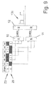
In der
Die Ansteuerschalteinrichtung 1 weist zu jedem der IGBTs 2a - 2f (S1 bis S6) eine zugeordnete Freilaufdiode 5a - 5f (D1 bis D6) auf. Die Ansteuerschalteinrichtung 1 erhält Signale einer Ansteuerelektronik 6 und wird von einem Gleichspannungszwischenkreis 7 gespeist. Die Spannung des Zwischenkreises 7 ist mit UZK bezeichnet. Beim erfindungsgemäßen Verfahren werden lediglich die Ansteuersignale für die IGBTs 2a - 2f verwendet, um ausschließlich anhand dieser Ansteuersignale die Ständerdrehfeldfrequenz bzw. Drehrichtung des Ständerdrehfeldes der Synchron- oder Asynchronmaschine 3 zu ermitteln.The
Die
In der
Die
In der
Immer dann, wenn der Zeiger Z1 aktiv wird, wird ein Speicher gesetzt. Wenn Zeiger Z4 aktiv wird, wird dieser Speicher zurückgesetzt. Ob die Zeiger Z1 und Z4 beteiligt sind, wird anhand der Schaltzustände der IGBTs 2a bis 2f abgefragt, wie in der
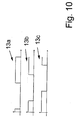
Die
In den
In der
Die
Sinn der Verriegelungszeiten ist es sicherzustellen, dass in einem Zweig des Pulswechselrichters gemäß der
- 1 Ansteuerschalteinrichtung1 drive switching device
- 2a, 2b, 2c, 2d, 2e, 2f IGBTs bzw. Schaltelemente (auch mit S1 bis S6 bezeichnet)2a, 2b, 2c, 2d, 2e, 2f IGBTs or switching elements (also denoted by S1 to S6)
- 3 Synchron- bzw. Asynchronmaschine3 synchronous or asynchronous machine
- 4a, 4b, 4c Motorwicklungen4a, 4b, 4c motor windings
- 5a, 5b, 5c, 5d, 5e, 5f Freilaufdioden (auch mit D1 bis D6 bezeichnet)5a, 5b, 5c, 5d, 5e, 5f freewheeling diodes (also denoted D1 to D6)
- 6 Ansteuerelektronik6 control electronics
- 7 Gleichspannungszwischenkreis7 DC voltage intermediate circuit
- 8a, 8b, 8c, 8d, 8e, 8f Sektoren Spannungsraumzeigerdarstellung (auch mit I bisVI bezeichnet)8a, 8b, 8c, 8d, 8e, 8f sectors voltage space pointer representation (also referred to as I to VI)
- 9 Schaltgerade9 switching line
- 10 &-Gatter10 & gate
- 11 &-Gatter11 & gate
- 12 Kästchen12 boxes
- 13a, 13b, 13c resultierender Signalverlauf, Rechteck-/ Binärsignal13a, 13b, 13c resulting signal waveform, rectangular / binary signal
- 14 resultierender Sollspannungsraumzeiger14 resulting target voltage space pointer
- 15a, 15b, 15c Zeitkoordinaten im Signalverlauf15a, 15b, 15c time coordinates in the waveform
- 16a, 16b, 16c, 16d, 16e, 16f Ein-/Ausschaltzeiten IGBTs bzw. Schaltelemente16a, 16b, 16c, 16d, 16e, 16f on / off times IGBTs or switching elements
- Z1, Z2, Z3, Z4, Z5, Z6, Z7, Z8 Spannungsraumzeiger (auch mit 1 bis 8 bezeichnet)Z1, Z2, Z3, Z4, Z5, Z6, Z7, Z8 voltage space vector (also denoted by 1 to 8 )
- a, b, c Raumachsena, b, c spatial axes
- iU, iv, iw Strömei U , i v , i w currents
- S Setzen SpeicherS put memory
- R Rücksetzen SpeicherR reset memory
- t Zeitt time
- U, V, W SpannungenU, V, W voltages
- uU, uv, uw zeitlich veränderliche Spannungenu U , u v , u w time-varying voltages
- UZK ZwischenkreisspannungU ZK DC link voltage
- U* resultierender Sollspannungsraumzeiger U * resulting target voltage space pointer
- α, β Achsen Stator-/ Ständerkoordinatensystemα, β axes Stator / stator coordinate system
Claims (14)
- A method for determining the electric stator rotating field frequency and/or the rotational direction of the stator rotating field of a synchronous or asynchronous machine (3) which is controlled by means of a control switching device (1) comprising at least one switching element (2a - 2f), the electric stator rotating field frequency and/or the rotational direction of the stator rotating field being determined exclusively by means of the control signals for the one or more switching elements (2a - 2f) of the control switching device (1), characterised in that within the framework of determining the electric stator rotating field frequency and/or the rotational direction of the stator rotating field of the synchronous or asynchronous machine (3) the period duration to the stator rotating field frequency is determined by means of a switching straight line (9) the extension of which in a target voltage space indicator representation indicates that a respective one of two voltage space indicators (Z1 and Z4; Z2 and Z5; Z3 and Z6) opposed to one another by 180° has become active in order to form a resulting target voltage space indicator (14), a memory being set (S) respectively at the start of the involvement of the one voltage space indicator (Z1 - Z3) in the formation of the resulting target voltage space indicator (14), said memory being re-set (R) when the involvement of the voltage space indicator (Z4 - Z6) opposed by 180° starts.
- The method according to Claim 1, characterised in that the control signals for the one or more switching elements (2a - 2f) are generated by a control electronic circuit (6) and/or are evaluated using a model or a representation with at least one voltage space indicator (Z1 - Z8) and/or at least one resulting target voltage space indicator (14).
- The method according to Claim 2, characterised in that the voltage space indicator or indicators (Z1 - Z8) and/or the resulting target voltage space indicator (14) is determined within the framework of current regulation and/or voltage/frequency control.
- The method according to any of the preceding claims, characterised in that a semiconductor switching element (2a - 2f) is used as at least one switching element (2a - 2f) of the control switching device (1) or that only semiconductor switching elements (2a - 2f) are used as switching elements (2a - 2f) of the control switching device (1), in particular biopolar transistors with an insulated gate electrode (IGBTs, 2a - 2f).
- The method according to any of the preceding claims, characterised in that at least one inverter is used as a control switching device (1), in particular a three-phase inverter and/or a pulse inverter and/or an inverter with bipolar transistors with an insulated gate electrode (2a - 2f) and respectively assigned free-wheeling diodes (5a - 5f) and/or a two-point inverter and/or an inverter fed by an intermediate DC circuit (7) and/or an inverter driving a three-phase load.
- The method according to any of the preceding claims, characterised in that in the case of a two-point inverter with six sectors (8a - 8f) in the target voltage space indicator representation it is implemented as a control switching device (1).
- The method according to any of the preceding claims, characterised in that the involvement of the two opposing voltage space indicators (Z1 and Z4; Z2 and Z5; Z3 and Z6) in the formation of the resulting target voltage space indicator (14) is determined by means of the switching states of the switching elements (2a - 2f) of the control switching device (1), in particular of the two-point inverter, the conditions for setting (S) and re-setting (R) the memory being determined on the basis of logic.
- The method according to any of the preceding claims, characterised in that the rotational direction of the stator rotating field, in particular in the case of a two-point inverter with six sectors (8a - 8f) in a target voltage space indicator representation as a control switching device (1), is determined by means of at least one, in particular at least one additional switching straight line, in the target voltage space indicator representation, in particular by means of an additional switching straight line which is shifted by 60° or 120° with respect to a switching straight line (9) in order to determine the period duration to the stator rotating field frequency.
- The method according to any of the preceding claims, characterised in that the stator rotating field frequency of the electric field, in particular in the case of a two-point inverter with six sectors (8a - 8f) in a target voltage space indicator representation as a control switching device (1) is determined by counting the flanks of the rectangular or binary signals (13a, 13b, 13c) produced by the resulting target voltage space indicator exceeding a switching straight line within a fixed interval of time and/or by measuring the time between two flanks of the rectangular and or binary signals (13a, 13b, 13c) produced by the resulting target voltage space indicator exceeding a switching straight line.
- The method according to any of Claims 6 to 10, characterised in that in the case of a two-point inverter with six sectors (8a - 8f) in a target voltage space indicator representation as the control switching device (1) all three of the rectangular or binary signals produced by the resulting target voltage space indicator exceeding the respective switching straight line are used to determine the stator rotating field frequency of the electric field.
- The method according to any of the preceding claims, characterised in that a locking time implemented in the control switching device (1) is taken into account within the framework of the method for determining the electric stator rotating field frequency and/or the rotational direction of the stator rotating field of a synchronous or asynchronous machine (3).
- The method according to any of the preceding claims, characterised in that the electric stator rotating field frequency and/or the rotational direction of the stator rotating field of the synchronous or asynchronous machine (3) is determined in the stationary state and/or for checking and/or making plausible the signals of at least one sensor and/or transmitter element.
- An apparatus, designed to determine the electric stator rotating field frequency and/or the rotational direction of the stator rotating field of a synchronous or asynchronous machine (3), the synchronous or asynchronous machine (3) being controllable by means of a control switching device (1) having at least one switching element (2a - 2f), in particular an apparatus which is designed to determine the electric stator rotating field frequency and/or the rotational direction of the stator rotating field according to a method according to any of the preceding claims, characterised in that the apparatus for determining the electric stator rotating field frequency and/or the rotational direction of the stator rotating field is designed exclusively by means of the control signals provided by a control electronic circuit (6) for the one or more switching elements (2a - 2f) of the control switching device (1) such that within the framework of determining the electric stator rotating field frequency and/or the rotational direction of the stator rotating field of the synchronous or asynchronous machine (3) the period duration to the stator rotating field frequency is determined by means of a switching straight line (9) the extension of which in a target voltage space indicator representation indicates that the respective one of two voltage space indicators (Z1 and Z4; Z2 and Z5; Z3 and Z6) opposing one another by 180° have become active in order to form a resulting target voltage space indicator (14), and that respectively at the start of the involvement of the one voltage space indicator (Z1 - Z3) in the formation of the resulting target voltage space indicator (14) a memory is set (S), which memory is re-set (R) when the involvement of the voltage space indicator (Z4 - Z6) opposing by 180° starts.
- A synchronous or asynchronous machine (3), characterised in that an apparatus according to Claim 13 is assigned to the synchronous or asynchronous machine (3).
Priority Applications (1)
| Application Number | Priority Date | Filing Date | Title |
|---|---|---|---|
| EP20100155176 EP2363948B1 (en) | 2010-03-02 | 2010-03-02 | Method for determining the electric stator rotating field frequency and/or the rotation direction of the stator rotating field frequency of a synchronous or asynchronous machine and corresponding device and synchronous or asynchronous machine. |
Applications Claiming Priority (1)
| Application Number | Priority Date | Filing Date | Title |
|---|---|---|---|
| EP20100155176 EP2363948B1 (en) | 2010-03-02 | 2010-03-02 | Method for determining the electric stator rotating field frequency and/or the rotation direction of the stator rotating field frequency of a synchronous or asynchronous machine and corresponding device and synchronous or asynchronous machine. |
Publications (2)
| Publication Number | Publication Date |
|---|---|
| EP2363948A1 EP2363948A1 (en) | 2011-09-07 |
| EP2363948B1 true EP2363948B1 (en) | 2014-12-03 |
Family
ID=42542803
Family Applications (1)
| Application Number | Title | Priority Date | Filing Date |
|---|---|---|---|
| EP20100155176 Active EP2363948B1 (en) | 2010-03-02 | 2010-03-02 | Method for determining the electric stator rotating field frequency and/or the rotation direction of the stator rotating field frequency of a synchronous or asynchronous machine and corresponding device and synchronous or asynchronous machine. |
Country Status (1)
| Country | Link |
|---|---|
| EP (1) | EP2363948B1 (en) |
Families Citing this family (1)
| Publication number | Priority date | Publication date | Assignee | Title |
|---|---|---|---|---|
| CN104300561A (en) * | 2014-09-30 | 2015-01-21 | 华北电力大学(保定) | Method for controlling three-phase four-leg transverter used for VSC-HVDC system |
Family Cites Families (7)
| Publication number | Priority date | Publication date | Assignee | Title |
|---|---|---|---|---|
| DE19530622A1 (en) * | 1995-08-21 | 1996-10-10 | Abb Daimler Benz Transp | Torque control for railway vehicle rotary field machine |
| DE19612988A1 (en) * | 1996-03-22 | 1997-09-25 | Abb Daimler Benz Transp | Determining the flux space vector position in coordinate system relative to stator for determining switching conditions for pulse inverter of induction motor |
| US6069808A (en) * | 1997-05-21 | 2000-05-30 | Texas Instruments Incorporated | Symmetrical space vector PWM DC-AC converter controller |
| AU2002213229A1 (en) * | 2000-10-13 | 2002-04-22 | Solectria Corporation | Improved distribution of space-vector pwm conduction losses |
| DE10207338A1 (en) | 2002-02-21 | 2003-09-11 | Infineon Technologies Ag | Method and device for detecting the motor position of an electric motor |
| US7126301B2 (en) | 2002-10-22 | 2006-10-24 | Matsushita Electric Industrial Co., Ltd. | Motor driver |
| JP4288614B2 (en) * | 2006-05-19 | 2009-07-01 | 日新電機株式会社 | Method and apparatus for controlling voltage-type three-phase inverter |
-
2010
- 2010-03-02 EP EP20100155176 patent/EP2363948B1/en active Active
Also Published As
| Publication number | Publication date |
|---|---|
| EP2363948A1 (en) | 2011-09-07 |
Similar Documents
| Publication | Publication Date | Title |
|---|---|---|
| DE102007054050B4 (en) | Semiconductor power converter | |
| DE112010001309B4 (en) | Drive control device for an electric motor | |
| DE10243602A1 (en) | Power converter designed to minimize circuit losses | |
| EP2875579B1 (en) | Method for determining the rotor position of an electronically-commuted multi-phase direct current motor | |
| DE112017003161B4 (en) | Power conversion device and logic circuit | |
| DE102013109624A1 (en) | Regulating device for permanent magnet synchronous motor, which prevents irreversible demagnetization of the permanent magnet and control system for it | |
| DE102016200241A1 (en) | CONTROL DEVICE FOR A TURNING ELECTRIC MACHINE | |
| EP2843828B1 (en) | Method and device for determining a pole wheel position of an electronically commutated electrical machine | |
| DE102014109513A1 (en) | Method and device for monitoring an electrical power circuit | |
| EP2026461B1 (en) | Method for sensorless control of a three-phase machine | |
| WO2012103993A1 (en) | Method and apparatus for calibrating at least one current sensor | |
| EP3017536B1 (en) | Method and device for the sensorless determination of a rotor position of an electric motor | |
| WO2011157472A1 (en) | Circuit arrangement for determining a voltage fluctuation of conductor potentials in an unearthed electrical network | |
| DE102016224178A1 (en) | Control of a six-phase PSM | |
| EP2363948B1 (en) | Method for determining the electric stator rotating field frequency and/or the rotation direction of the stator rotating field frequency of a synchronous or asynchronous machine and corresponding device and synchronous or asynchronous machine. | |
| DE102010033459A1 (en) | Method for error detection in the control of a rotating field motor | |
| EP3619805B1 (en) | Method and device for determining the position angle of a rotor in an electric synchronous machine | |
| DE102012110271B4 (en) | Device and method for braking an electric motor | |
| DE102013222007A1 (en) | A processor, apparatus, method and computer program for controlling an emergency operation of a multiphase induction machine upon interruption of a first phase current of a first phase of the induction machine | |
| WO2011157470A1 (en) | Circuit arrangement for determining a voltage fluctuation of conductor potentials in an unearthed electrical network | |
| EP2777144B1 (en) | Method for calibrating a multiphase inverter, operating apparatus, computer program, and computer program product | |
| DE102016204854A1 (en) | Determining a short-circuit current in the phases of an electric machine controlled by an inverter | |
| DE112019007652T5 (en) | ESTIMATION DEVICE AND AC MOTOR DRIVE DEVICE | |
| EP3857704A1 (en) | Method for determining a correction value which describes an angular difference between an assumed and an actual position of a d-axis, control device and inverter | |
| DE102017211219A1 (en) | Method and device for operating an electric machine, in particular a steering assistance drive |
Legal Events
| Date | Code | Title | Description |
|---|---|---|---|
| PUAI | Public reference made under article 153(3) epc to a published international application that has entered the european phase |
Free format text: ORIGINAL CODE: 0009012 |
|
| AK | Designated contracting states |
Kind code of ref document: A1 Designated state(s): AT BE BG CH CY CZ DE DK EE ES FI FR GB GR HR HU IE IS IT LI LT LU LV MC MK MT NL NO PL PT RO SE SI SK SM TR |
|
| AX | Request for extension of the european patent |
Extension state: AL BA ME RS |
|
| RIN1 | Information on inventor provided before grant (corrected) |
Inventor name: VILLWOCK, SEBASTIAN Inventor name: ZATOCIL, HEIKO |
|
| 17P | Request for examination filed |
Effective date: 20120621 |
|
| 17Q | First examination report despatched |
Effective date: 20131128 |
|
| REG | Reference to a national code |
Ref country code: DE Ref legal event code: R079 Ref document number: 502010008383 Country of ref document: DE Free format text: PREVIOUS MAIN CLASS: H02M0007538700 Ipc: H02P0027080000 |
|
| RIC1 | Information provided on ipc code assigned before grant |
Ipc: H02M 7/5387 20070101ALI20140512BHEP Ipc: H02P 27/12 20060101ALI20140512BHEP Ipc: H02P 27/08 20060101AFI20140512BHEP |
|
| GRAP | Despatch of communication of intention to grant a patent |
Free format text: ORIGINAL CODE: EPIDOSNIGR1 |
|
| INTG | Intention to grant announced |
Effective date: 20140626 |
|
| GRAS | Grant fee paid |
Free format text: ORIGINAL CODE: EPIDOSNIGR3 |
|
| GRAA | (expected) grant |
Free format text: ORIGINAL CODE: 0009210 |
|
| AK | Designated contracting states |
Kind code of ref document: B1 Designated state(s): AT BE BG CH CY CZ DE DK EE ES FI FR GB GR HR HU IE IS IT LI LT LU LV MC MK MT NL NO PL PT RO SE SI SK SM TR |
|
| REG | Reference to a national code |
Ref country code: GB Ref legal event code: FG4D Free format text: NOT ENGLISH |
|
| REG | Reference to a national code |
Ref country code: AT Ref legal event code: REF Ref document number: 699875 Country of ref document: AT Kind code of ref document: T Effective date: 20141215 Ref country code: CH Ref legal event code: EP |
|
| REG | Reference to a national code |
Ref country code: IE Ref legal event code: FG4D Free format text: LANGUAGE OF EP DOCUMENT: GERMAN |
|
| REG | Reference to a national code |
Ref country code: DE Ref legal event code: R096 Ref document number: 502010008383 Country of ref document: DE Effective date: 20150115 Ref country code: CH Ref legal event code: NV Representative=s name: SCHNEIDER FELDMANN AG PATENT- UND MARKENANWAEL, CH |
|
| REG | Reference to a national code |
Ref country code: NL Ref legal event code: T3 |
|
| PG25 | Lapsed in a contracting state [announced via postgrant information from national office to epo] |
Ref country code: ES Free format text: LAPSE BECAUSE OF FAILURE TO SUBMIT A TRANSLATION OF THE DESCRIPTION OR TO PAY THE FEE WITHIN THE PRESCRIBED TIME-LIMIT Effective date: 20141203 Ref country code: FI Free format text: LAPSE BECAUSE OF FAILURE TO SUBMIT A TRANSLATION OF THE DESCRIPTION OR TO PAY THE FEE WITHIN THE PRESCRIBED TIME-LIMIT Effective date: 20141203 Ref country code: NO Free format text: LAPSE BECAUSE OF FAILURE TO SUBMIT A TRANSLATION OF THE DESCRIPTION OR TO PAY THE FEE WITHIN THE PRESCRIBED TIME-LIMIT Effective date: 20150303 Ref country code: LT Free format text: LAPSE BECAUSE OF FAILURE TO SUBMIT A TRANSLATION OF THE DESCRIPTION OR TO PAY THE FEE WITHIN THE PRESCRIBED TIME-LIMIT Effective date: 20141203 |
|
| REG | Reference to a national code |
Ref country code: LT Ref legal event code: MG4D |
|
| PG25 | Lapsed in a contracting state [announced via postgrant information from national office to epo] |
Ref country code: SE Free format text: LAPSE BECAUSE OF FAILURE TO SUBMIT A TRANSLATION OF THE DESCRIPTION OR TO PAY THE FEE WITHIN THE PRESCRIBED TIME-LIMIT Effective date: 20141203 Ref country code: LV Free format text: LAPSE BECAUSE OF FAILURE TO SUBMIT A TRANSLATION OF THE DESCRIPTION OR TO PAY THE FEE WITHIN THE PRESCRIBED TIME-LIMIT Effective date: 20141203 Ref country code: HR Free format text: LAPSE BECAUSE OF FAILURE TO SUBMIT A TRANSLATION OF THE DESCRIPTION OR TO PAY THE FEE WITHIN THE PRESCRIBED TIME-LIMIT Effective date: 20141203 Ref country code: GR Free format text: LAPSE BECAUSE OF FAILURE TO SUBMIT A TRANSLATION OF THE DESCRIPTION OR TO PAY THE FEE WITHIN THE PRESCRIBED TIME-LIMIT Effective date: 20150304 Ref country code: CY Free format text: LAPSE BECAUSE OF FAILURE TO SUBMIT A TRANSLATION OF THE DESCRIPTION OR TO PAY THE FEE WITHIN THE PRESCRIBED TIME-LIMIT Effective date: 20141203 |
|
| PG25 | Lapsed in a contracting state [announced via postgrant information from national office to epo] |
Ref country code: SK Free format text: LAPSE BECAUSE OF FAILURE TO SUBMIT A TRANSLATION OF THE DESCRIPTION OR TO PAY THE FEE WITHIN THE PRESCRIBED TIME-LIMIT Effective date: 20141203 Ref country code: EE Free format text: LAPSE BECAUSE OF FAILURE TO SUBMIT A TRANSLATION OF THE DESCRIPTION OR TO PAY THE FEE WITHIN THE PRESCRIBED TIME-LIMIT Effective date: 20141203 Ref country code: PT Free format text: LAPSE BECAUSE OF FAILURE TO SUBMIT A TRANSLATION OF THE DESCRIPTION OR TO PAY THE FEE WITHIN THE PRESCRIBED TIME-LIMIT Effective date: 20150403 Ref country code: RO Free format text: LAPSE BECAUSE OF FAILURE TO SUBMIT A TRANSLATION OF THE DESCRIPTION OR TO PAY THE FEE WITHIN THE PRESCRIBED TIME-LIMIT Effective date: 20141203 Ref country code: CZ Free format text: LAPSE BECAUSE OF FAILURE TO SUBMIT A TRANSLATION OF THE DESCRIPTION OR TO PAY THE FEE WITHIN THE PRESCRIBED TIME-LIMIT Effective date: 20141203 |
|
| PG25 | Lapsed in a contracting state [announced via postgrant information from national office to epo] |
Ref country code: IS Free format text: LAPSE BECAUSE OF FAILURE TO SUBMIT A TRANSLATION OF THE DESCRIPTION OR TO PAY THE FEE WITHIN THE PRESCRIBED TIME-LIMIT Effective date: 20150403 Ref country code: PL Free format text: LAPSE BECAUSE OF FAILURE TO SUBMIT A TRANSLATION OF THE DESCRIPTION OR TO PAY THE FEE WITHIN THE PRESCRIBED TIME-LIMIT Effective date: 20141203 |
|
| REG | Reference to a national code |
Ref country code: DE Ref legal event code: R097 Ref document number: 502010008383 Country of ref document: DE |
|
| PLBE | No opposition filed within time limit |
Free format text: ORIGINAL CODE: 0009261 |
|
| STAA | Information on the status of an ep patent application or granted ep patent |
Free format text: STATUS: NO OPPOSITION FILED WITHIN TIME LIMIT |
|
| PG25 | Lapsed in a contracting state [announced via postgrant information from national office to epo] |
Ref country code: DK Free format text: LAPSE BECAUSE OF FAILURE TO SUBMIT A TRANSLATION OF THE DESCRIPTION OR TO PAY THE FEE WITHIN THE PRESCRIBED TIME-LIMIT Effective date: 20141203 Ref country code: MC Free format text: LAPSE BECAUSE OF FAILURE TO SUBMIT A TRANSLATION OF THE DESCRIPTION OR TO PAY THE FEE WITHIN THE PRESCRIBED TIME-LIMIT Effective date: 20141203 Ref country code: LU Free format text: LAPSE BECAUSE OF FAILURE TO SUBMIT A TRANSLATION OF THE DESCRIPTION OR TO PAY THE FEE WITHIN THE PRESCRIBED TIME-LIMIT Effective date: 20150302 |
|
| 26N | No opposition filed |
Effective date: 20150904 |
|
| REG | Reference to a national code |
Ref country code: IE Ref legal event code: MM4A |
|
| PG25 | Lapsed in a contracting state [announced via postgrant information from national office to epo] |
Ref country code: IE Free format text: LAPSE BECAUSE OF NON-PAYMENT OF DUE FEES Effective date: 20150302 |
|
| PG25 | Lapsed in a contracting state [announced via postgrant information from national office to epo] |
Ref country code: SI Free format text: LAPSE BECAUSE OF FAILURE TO SUBMIT A TRANSLATION OF THE DESCRIPTION OR TO PAY THE FEE WITHIN THE PRESCRIBED TIME-LIMIT Effective date: 20141203 |
|
| REG | Reference to a national code |
Ref country code: FR Ref legal event code: PLFP Year of fee payment: 7 |
|
| PG25 | Lapsed in a contracting state [announced via postgrant information from national office to epo] |
Ref country code: MT Free format text: LAPSE BECAUSE OF FAILURE TO SUBMIT A TRANSLATION OF THE DESCRIPTION OR TO PAY THE FEE WITHIN THE PRESCRIBED TIME-LIMIT Effective date: 20141203 |
|
| REG | Reference to a national code |
Ref country code: FR Ref legal event code: PLFP Year of fee payment: 8 |
|
| PG25 | Lapsed in a contracting state [announced via postgrant information from national office to epo] |
Ref country code: SM Free format text: LAPSE BECAUSE OF FAILURE TO SUBMIT A TRANSLATION OF THE DESCRIPTION OR TO PAY THE FEE WITHIN THE PRESCRIBED TIME-LIMIT Effective date: 20141203 Ref country code: BG Free format text: LAPSE BECAUSE OF FAILURE TO SUBMIT A TRANSLATION OF THE DESCRIPTION OR TO PAY THE FEE WITHIN THE PRESCRIBED TIME-LIMIT Effective date: 20141203 Ref country code: HU Free format text: LAPSE BECAUSE OF FAILURE TO SUBMIT A TRANSLATION OF THE DESCRIPTION OR TO PAY THE FEE WITHIN THE PRESCRIBED TIME-LIMIT; INVALID AB INITIO Effective date: 20100302 |
|
| PG25 | Lapsed in a contracting state [announced via postgrant information from national office to epo] |
Ref country code: BE Free format text: LAPSE BECAUSE OF NON-PAYMENT OF DUE FEES Effective date: 20150331 |
|
| PG25 | Lapsed in a contracting state [announced via postgrant information from national office to epo] |
Ref country code: TR Free format text: LAPSE BECAUSE OF FAILURE TO SUBMIT A TRANSLATION OF THE DESCRIPTION OR TO PAY THE FEE WITHIN THE PRESCRIBED TIME-LIMIT Effective date: 20141203 |
|
| REG | Reference to a national code |
Ref country code: FR Ref legal event code: PLFP Year of fee payment: 9 |
|
| PG25 | Lapsed in a contracting state [announced via postgrant information from national office to epo] |
Ref country code: MK Free format text: LAPSE BECAUSE OF FAILURE TO SUBMIT A TRANSLATION OF THE DESCRIPTION OR TO PAY THE FEE WITHIN THE PRESCRIBED TIME-LIMIT Effective date: 20141203 |
|
| REG | Reference to a national code |
Ref country code: CH Ref legal event code: PFA Owner name: BAUMUELLER NUERNBERG GMBH, DE Free format text: FORMER OWNER: BAUMUELLER NUERNBERG GMBH, DE |
|
| PGFP | Annual fee paid to national office [announced via postgrant information from national office to epo] |
Ref country code: NL Payment date: 20220322 Year of fee payment: 13 |
|
| PGFP | Annual fee paid to national office [announced via postgrant information from national office to epo] |
Ref country code: FR Payment date: 20230320 Year of fee payment: 14 Ref country code: AT Payment date: 20230317 Year of fee payment: 14 |
|
| PGFP | Annual fee paid to national office [announced via postgrant information from national office to epo] |
Ref country code: GB Payment date: 20230323 Year of fee payment: 14 Ref country code: DE Payment date: 20230320 Year of fee payment: 14 |
|
| PGFP | Annual fee paid to national office [announced via postgrant information from national office to epo] |
Ref country code: IT Payment date: 20230331 Year of fee payment: 14 Ref country code: CH Payment date: 20230402 Year of fee payment: 14 |
|
| REG | Reference to a national code |
Ref country code: NL Ref legal event code: MM Effective date: 20230401 |
|
| PG25 | Lapsed in a contracting state [announced via postgrant information from national office to epo] |
Ref country code: NL Free format text: LAPSE BECAUSE OF NON-PAYMENT OF DUE FEES Effective date: 20230401 |