EP2363740A1 - Microscope apparatus and observation position reproduction method - Google Patents
Microscope apparatus and observation position reproduction method Download PDFInfo
- Publication number
- EP2363740A1 EP2363740A1 EP11001458A EP11001458A EP2363740A1 EP 2363740 A1 EP2363740 A1 EP 2363740A1 EP 11001458 A EP11001458 A EP 11001458A EP 11001458 A EP11001458 A EP 11001458A EP 2363740 A1 EP2363740 A1 EP 2363740A1
- Authority
- EP
- European Patent Office
- Prior art keywords
- image
- circular sample
- unit
- center position
- coordinates
- Prior art date
- Legal status (The legal status is an assumption and is not a legal conclusion. Google has not performed a legal analysis and makes no representation as to the accuracy of the status listed.)
- Granted
Links
- 238000000034 method Methods 0.000 title claims description 56
- 238000004364 calculation method Methods 0.000 claims abstract description 49
- 230000008569 process Effects 0.000 claims description 23
- 230000003287 optical effect Effects 0.000 claims description 18
- 238000001514 detection method Methods 0.000 claims description 13
- 230000004048 modification Effects 0.000 description 38
- 238000012986 modification Methods 0.000 description 38
- 230000004044 response Effects 0.000 description 8
- 230000008859 change Effects 0.000 description 5
- 238000003909 pattern recognition Methods 0.000 description 5
- 239000000428 dust Substances 0.000 description 4
- 238000003672 processing method Methods 0.000 description 4
- 230000002776 aggregation Effects 0.000 description 3
- 238000004220 aggregation Methods 0.000 description 3
- 238000003708 edge detection Methods 0.000 description 3
- 230000006870 function Effects 0.000 description 3
- PXFBZOLANLWPMH-UHFFFAOYSA-N 16-Epiaffinine Natural products C1C(C2=CC=CC=C2N2)=C2C(=O)CC2C(=CC)CN(C)C1C2CO PXFBZOLANLWPMH-UHFFFAOYSA-N 0.000 description 2
- 230000004913 activation Effects 0.000 description 2
- 238000012937 correction Methods 0.000 description 2
- 230000000694 effects Effects 0.000 description 2
- 230000002123 temporal effect Effects 0.000 description 2
- 230000000007 visual effect Effects 0.000 description 2
- 239000004698 Polyethylene Substances 0.000 description 1
- 230000000295 complement effect Effects 0.000 description 1
- 238000012217 deletion Methods 0.000 description 1
- 230000037430 deletion Effects 0.000 description 1
- 238000001914 filtration Methods 0.000 description 1
- 239000011521 glass Substances 0.000 description 1
- 239000003550 marker Substances 0.000 description 1
- 239000000463 material Substances 0.000 description 1
- 229910044991 metal oxide Inorganic materials 0.000 description 1
- 150000004706 metal oxides Chemical class 0.000 description 1
- 238000000386 microscopy Methods 0.000 description 1
- 230000004660 morphological change Effects 0.000 description 1
- 230000010287 polarization Effects 0.000 description 1
- -1 polyethylene Polymers 0.000 description 1
- 229920000573 polyethylene Polymers 0.000 description 1
- 239000004065 semiconductor Substances 0.000 description 1
- 239000000758 substrate Substances 0.000 description 1
- 238000012546 transfer Methods 0.000 description 1
- 238000002604 ultrasonography Methods 0.000 description 1
- 238000012795 verification Methods 0.000 description 1
Images


Classifications
-
- G—PHYSICS
- G02—OPTICS
- G02B—OPTICAL ELEMENTS, SYSTEMS OR APPARATUS
- G02B21/00—Microscopes
- G02B21/36—Microscopes arranged for photographic purposes or projection purposes or digital imaging or video purposes including associated control and data processing arrangements
- G02B21/365—Control or image processing arrangements for digital or video microscopes
- G02B21/367—Control or image processing arrangements for digital or video microscopes providing an output produced by processing a plurality of individual source images, e.g. image tiling, montage, composite images, depth sectioning, image comparison
-
- G—PHYSICS
- G02—OPTICS
- G02B—OPTICAL ELEMENTS, SYSTEMS OR APPARATUS
- G02B21/00—Microscopes
- G02B21/16—Microscopes adapted for ultraviolet illumination ; Fluorescence microscopes
-
- G—PHYSICS
- G02—OPTICS
- G02B—OPTICAL ELEMENTS, SYSTEMS OR APPARATUS
- G02B21/00—Microscopes
- G02B21/36—Microscopes arranged for photographic purposes or projection purposes or digital imaging or video purposes including associated control and data processing arrangements
- G02B21/365—Control or image processing arrangements for digital or video microscopes
-
- G—PHYSICS
- G02—OPTICS
- G02B—OPTICAL ELEMENTS, SYSTEMS OR APPARATUS
- G02B21/00—Microscopes
- G02B21/0004—Microscopes specially adapted for specific applications
- G02B21/0088—Inverse microscopes
Abstract
Description
- The present invention relates to a microscope apparatus having a function of reproducing an observation position of a sample.
- Conventionally, position alignment (position reproduction) of an observation portion of a sample is performed with manual operations of a user in a microscope observation. The manual operations are performed, for example, as follows. Initially, a magnification is set to a low ratio, and a stage is moved, for example, by using a mark or the like provided in a view field of an eyepiece lens so that an observation portion of a sample is located at an approximate position (such as the center of an observation image). Similar operations are performed after switching the magnification to a high ratio next. In this way, the position alignment of the observation portion is performed. However, such position alignment performed with user manual operations has not only low operation efficiency due to a lot of troublesomeness but a large error and low position productivity.
- Accordingly, in order to overcome such problems, microscope apparatuses having a stage position reproduction function have been developed. As one example of such microscope apparatuses, an electric stage microscope that includes a stage provided with a length measuring instrument using a magnetic scale, an optical scale and laser interference, and that has a function of grasping the amount of a move or the current position of the stage by feeding a signal from the length measuring instrument back to a control unit is cited.
- However, such an electric stage microscope has a problem that an observation position cannot be reproduced due to a rotational shift and a different orientation of a sample depending on a position where the sample once removed from a stage is again put and fixed on the stage.
- To overcome such a problem, Patent Document 1 (Japanese Laid-open Patent Publication No.
2004-205366 - However, the microscope apparatus proposed by
Patent Document 1 has two problems of a position reproduction method. One of them is that a troublesome operation for attaching a pattern to a sample is needed. The other is that the pattern attached to the sample causes a rotational shift depending on a position where the sample is put, leading to difficulty in position reproduction. - In light of the above described circumstances, an object of the present invention is to provide a microscope apparatus and an observation position reproduction method, which can reproduce an observation position of a circular sample with high accuracy.
- An apparatus in one aspect of the present invention is a microscope apparatus including an image capturing unit, a center position calculation unit, a recognition unit, a rotational shift angle calculation unit and a position reproduction unit. The image capturing unit captures an observation image. The center position calculation unit calculates coordinates of a center position of a circular sample based on an image of the circular sample, which is obtained by the image capturing unit. The recognition unit recognizes a pattern image of a predetermined area based on the coordinates of the center position, which are calculated by the center position calculation unit, from the image of the circular sample, which is obtained by the image capturing unit. The storage unit stores the pattern image recognized by the recognition unit. The rotational shift angle calculation unit calculates a rotational shift angle between a first pattern image and a second pattern image. Here, the first pattern image is a pattern image recognized by the recognition unit from an image of the circular sample, which is obtained by the image capturing unit in a first period. The second pattern image is a pattern image recognized by the recognition unit from an image of the circular sample, which is obtained by the image capturing unit in a second period later than the first period. The position reproduction unit corrects a rotational shift of the circular sample based on the rotational shift angle calculated by the rotational shift angle calculation unit, and reproduces a position of the circular sample in the first period.
-
-
FIG. 1 schematically illustrates an entire configuration of a microscope apparatus according to an embodiment; -
FIG. 2 is a flowchart illustrating operations of the microscope apparatus according to the embodiment; -
FIG. 3 schematically illustrates one example of a GUI screen displayed on a display unit; -
FIG. 4 is a graph of calculated characteristic data; -
FIG. 5 is a flowchart illustrating details of an operation (S4) for calculating coordinates of a center position of a circular sample; -
FIG. 6 is an explanatory view of an edge point detection process executed in S43; -
FIG. 7 is an explanatory view of a center position coordinates calculation process executed in S44; -
FIG. 8 is an explanatory view of an example of operations performed when edge points of a circular sample are manually detected; -
FIG. 9 is an explanatory view of sample ID new registration made in S6; -
FIG. 10 illustrates one example of an image of a predetermined area, which is recognized as a reference pattern image from an image of a bottom surface of the circular sample; -
FIG. 11 is an explanatory view of a change of an origin; -
FIG. 12 illustrates an example where XY coordinates of an observation position are represented with polar coordinates; -
FIG. 13 illustrates one example of a GUI screen at a time point when an image at an observation position is obtained twice; -
FIG. 14 illustrates a folder structure of images and information stored in a position reproduction information storage unit in association with a newly registered sample ID; -
FIG. 15 illustrates a dialog displayed on a display unit when a user inputs a sample ID of a circular sample; -
FIG. 16 illustrates an example of calculating a rotational shift angle by using pattern matching; -
FIG. 17 schematically illustrates an entire configuration of a microscope apparatus according to a modification example 1; -
FIG. 18 schematically illustrates an entire configuration of a microscope apparatus according to a modification example 2; -
FIG. 19 is a flowchart illustrating operations according to a modification example 3; -
FIG. 20 is an explanatory view of area detection when an area that does not rotate with a rotation of an XYZ θ electric microscope stage is detected from a live image in a modification example 4; and -
FIG. 21 illustrates an example of calculating a rotational shift angle by using pattern matching according to a modification example 5. - An embodiment according to the present invention is described below with reference to the drawings.
-
FIG. 1 schematically illustrates an entire configuration of a microscope apparatus according to the embodiment of the present invention. - As illustrated in this figure, the microscope apparatus according to this embodiment includes a
microscope 100, acontrol unit 200, adisplay unit 300 and aninput unit 400. Themicroscope 100, thedisplay unit 300 and theinput unit 400 are electrically connected to thecontrol unit 200. - The
microscope 100 is an inverted microscope including alight source 101, acondenser 102, an XYZ θelectric stage 104 on which acircular sample 103 is put, arevolver 105, animage capturing unit 106,objective lenses 107, a Zaxis focus handle 108, and anXY θ handle 109. - This embodiment assumes the use of a culture dish (also called a schale, a petri dish or the like) used to culture live cells as the
circular sample 103. Accordingly, this embodiment adopts, as themicroscope 100, an inverted microscope normally used to observe a culture dish from the viewpoints of a WD (Working Distance) and a focal distance of anobjective lens 107 and from a hygienic viewpoint. However, an erect microscope can be adopted as a matter of course. - The
circular sample 103 is a culture dish made of, for example, polyethylene, glass or the like, and has a diameter of, for example, 35mm, 60mm or the like. However, thecircular sample 103 is not limited to these materials and diameters. Thecircular sample 103 is set (put, fixed) on the XYZ θelectric stage 104. Thecircular sample 103 can be removed/set from/on the XYZ θelectric stage 104, and a user can set an arbitrarycircular sample 103 on the XYZ θelectric stage 104. - The XYZ θ
electric stage 104 can move in XY direction that is a horizontal direction (the direction vertical to the paper sheet ofFIG. 1 ), and in Z direction that is the vertical direction (the upward and downward direction of the paper sheet ofFIG. 1 ) under the control of thecontrol unit 200 by using, for example, a linear motor, a stepping motor, a piezoelectric or ultrasound motor or the like as an actuator. Moreover, thestage 104 is configured to be rotatable in θ direction (a rotation direction using an axis parallel to the Z direction as a rotational axis). As a result, a user can move the XYZ θelectric stage 104 to a desired XYZ coordinates position by specifying, for example, XYZ coordinates via theinput unit 400. Additionally, the XYZ θelectric stage 104 is also configured to be movable in the XY direction and the Z direction and to be rotatable in the θ direction with a user manual operation of the Z axis focus handle 108 and the XY θhandle 109. - The
image capturing unit 106 is one example of the image capturing unit for capturing an observation image. As theimage capturing unit 106, for example, a CCD (Charge Coupled Device) camera, a CMOS (Complementary Metal Oxide Semiconductor) camera, a video camera, and a known photodetector such as a photomultiplier tube or the like can be used. However, theimage capturing unit 106 is not limited to these devices. - The
revolver 105 is provided with the plurality ofobjective lenses 107 such as a bright-field objective lens, a phase difference objective lens or the like. - Additionally, a phase plate, not illustrated, can be further inserted in the optical path in the
condenser 102 at the time of a phase difference observation. Moreover, a DIC (Differential Interference Contrast) prism and a polarization plate can be further inserted in the optical path in thecondenser 102 and therevolver 105 at the time of a differential interference observation. - With the
microscope 100 having such a configuration, when light is emitted from thelight source 101, the emitted light passes through thecondenser 102, and is irradiated on thecircular sample 103 set on the XYZ θelectric stage 104. Then, the light that transmits through thecircular sample 103 passes through theobjective lens 107, and is formed as an observation image on theimage capturing unit 106 via a tube lens not illustrated. The formed observation image is captured by the image capturing unit 106 (a digital image process is executed for the formed observation image) , and the image is transmitted to thecontrol unit 200 as a digital signal. The digital signal transmitted to thecontrol unit 200 is thereafter displayed as an image, for example, on thedisplay unit 300. - The
control unit 200 includes a CPU and amemory 200a. The CPU reads and executes a control program stored in thememory 200a, thereby controlling operations of the entire microscope apparatus. Moreover, in thecontrol unit 200, the CPU executes the control program stored in thememory 200a, thereby implementing a centerposition calculation unit 201, apattern recognition unit 202, a rotational shiftangle calculation unit 204, aposition reproduction unit 205, amicroscope control unit 206 and afocus adjustment unit 207. Here, the centerposition calculation unit 201 is one example of the center position calculation unit for calculating coordinates of the center position of thecircular sample 103 based on an image of thecircular sample 103, which is obtained by theimage capturing unit 106. Assume that the coordinates of the center position of thecircular sample 103 indicate coordinates of the center position of the circle of thecircular sample 103 on an XY plane that does not include a Z coordinate. Thepattern recognition unit 202 is one example of the recognition unit for recognizing a pattern image of a predetermined area based on the coordinates of the center position, which are calculated by the centerposition calculation unit 201, from the image of thecircular sample 103, which is obtained by theimage capturing unit 106. The rotational shiftangle calculation unit 204 is one example of the rotational shift angle calculation unit for calculating a rotational shift angle between a first pattern image and a second pattern image. The first pattern image is a pattern image recognized by thepattern recognition unit 202 from an image of thecircular image 103, which is obtained by theimage capturing unit 106 in a first period. The second pattern image is a pattern image recognized by thepattern recognition unit 202 from an image of thecircular sample 103, which is obtained by theimage capturing unit 106 in a second period later than the first period. Theposition reproduction unit 205 is one example of the position reproduction unit for correcting a rotational shift of thecircular sample 103 based on the rotational shift angle calculated by the rotational shiftangle calculation unit 204 and for reproducing the position of thecircular sample 103 in the first period. Themicroscope control unit 206 is one example of means for controlling themicroscope 100, and transmits/receives data (for example, transmits a control signal, receives a digital signal from the image capturing unit 106) to/from themicroscope 100. Note that themicroscope control unit 206 can also operate under the control of another unit (such as the centerposition calculation unit 201, theposition reproduction unit 205, thefocus adjustment unit 207 or the like) within thecontrol unit 200. Thefocus adjustment unit 207 is one example of means for making a focus adjustment, and, for example, calculates a focus adjustment value and performs other operations. - The
control unit 200 further includes apattern storage unit 203 and a position reproductioninformation storage unit 208. Thepattern storage unit 203 is one example of the storage unit. In thepattern storage unit 203, a pattern image recognized by thepattern recognition unit 202 is stored. In the position reproductioninformation storage unit 208, data of position reproduction, observation data of thecircular sample 103, and the like are stored. - The
input unit 400 accepts various types of instructions, settings and the like from a user. Thedisplay unit 300 displays a GUI (Graphical User Interface) screen, various types of dialogs, which will be described later, and the like. - For example, if a user sets parameters via the
input unit 400, values of the set parameters (parameters after being changed) are displayed on thedisplay unit 300, and control signals according to the values of the parameters are output from themicroscope control unit 206 of thecontrol unit 200 to themicroscope 100. In this way, the user can operate themicroscope 100 via theinput unit 400. - As operations of the
microscope 100 that the user can operate via theinput unit 400, for example, the following operations are cited. - voltage adjustment of the
light source 101 - driving of the XYZ θ
electric stage 104 - image capturing from the
image capturing unit 106 - magnification switching of the
objective lens 107 - observation method (also called microscopy) switching (changing the
condenser 102, therevolver 105 and the objective lens 107) - All of these operations are not inoperable only electrically. For example, the XYZ θ
electric stage 104 can be manually operated by using the Z axis focus handle 108 and the XY θhandle 109 as described above. - The microscope apparatus according to this embodiment assumes that the
image capturing unit 106 is a CCD camera, thecontrol unit 200 is a PC (Personal Computer) , thedisplay unit 300 is an output device such as a display or the like, and theinput unit 400 is an input device such as a keyboard, a mouse or the like. Moreover, thecontrol unit 200, thedisplay unit 300 and theinput unit 400 are assumed to be interconnected via a bus or an interface. However, the microscope apparatus is not limited to this implementation. Furthermore, the microscope apparatus according to this embodiment is configured so that themicroscope control unit 206 is included in thecontrol unit 200. However, themicroscope control unit 206 can be provided independently of thecontrol unit 200. In this case, for example, a control box as themicroscope control unit 206 can be provided separately from a PC as thecontrol unit 200. - Operations of the microscope apparatus according to this embodiment are described in detail next.
- The operations of the microscope apparatus according to this embodiment include the following operations as basic operations.
- Initially, in a first period, an image of the
circular sample 103 is captured, and coordinates of a first center position of thecircular sample 103 are calculated based on the obtained image. Moreover, in the first period, the image of thecircular sample 103 is captured, and a first pattern image of a predetermined area is recognized from the obtained image based on the coordinates of the first center position of thecircular sample 103. Next, in a second period later than the first period, an image of thecircular sample 103 is captured, and coordinates of a second center position of thecircular sample 103 are calculated based on the obtained image. Moreover, in the second period, the image of thecircular sample 103 is captured, and a second pattern image of a predetermined area is recognized from the obtained image based on the coordinates of the second center position of thecircular sample 103. Then, a rotational shift angle between the first pattern image recognized in the first period and the second pattern image recognized in the second period is calculated, and a rotational shift of thecircular sample 103 is corrected based on the rotational shift angle, and the position of thecircular sample 103 in the first period is reproduced. - Here, operations of the microscope apparatus performed when a user cultures live cells and observes a temporal observation (also called a time lapse observation) by using a circular sample (culture dish) are described as one example of the operations of the microscope apparatus according to this embodiment. In such a case, the culture dish needs to be put fully stationarily in a particular culture environment such as an incubator or the like in order to culture live cells. For this reason, the culture dish is taken out of the culture environment at an observation, and returned to the culture environment upon termination of the observation. At this time, a user needs to manually set the culture dish on the XYZ θ
electric stage 104. When such manual operations are repeated, it is difficult to set the culture dish at the same position and in the same orientation every time. Accordingly, with the microscope apparatus according to this embodiment, an observation position shift that can possibly occur when a culture dish is observed by a plurality of times while repeating such manual operations is corrected with operations described in detail below. -
FIG. 2 is a flowchart illustrating the operations of the microscope apparatus according to this embodiment. - The flowchart illustrated in this figure represents both the operations of a user and those of the microscope apparatus for the sake of explanation. The CPU of the
control unit 200 reads and executes the control program stored in thememory 200a, whereby the operations of the microscope apparatus are implemented. - The flowchart illustrated in
FIG. 2 includes operations at the first observation and those at the second or subsequent observation. Main operations among the operations at the first observation are operations of step (hereinafter referred to simply as "S") 6 to S8. Moreover, main operations among the operations at the second or subsequent observation are operations of S11 to S16. - Initially, the operations at the first observation are described.
- In
FIG. 2 , the microscope apparatus is initially activated in S1. The activation is performed under the control of thecontrol unit 200 in response to a user operation of powering on the respective units such as themicroscope 100, thecontrol unit 200, thedisplay unit 300 and the like. At the activation, for example, anobjective lens 107 having the lowest magnification is inserted in the optical path, and at the same time, the XYZ θelectric stage 104 moves to a predetermined initial position as initial operations of the microscope apparatus. Moreover, a GUI screen for enabling operations for the microscope apparatus is displayed on thedisplay unit 300. As a result, a user operates the GUI screen displayed on thedisplay unit 300 via theinput unit 400, whereby various types of operations (including the above described operations for the microscope 100) for the microscope apparatus can be performed. -
FIG. 3 schematically illustrates one example of the GUI screen displayed on thedisplay unit 300 at this time. - As illustrated in this figure, the GUI screen includes a
camera control area 310, a stage control area 320, an objectivelens control area 330, animage display area 340, an entiremap image area 350 and a capturingcontrol area 360. - The
camera control area 310 is an operation area for controlling theimage capturing unit 106. Thecamera control area 310 includes an AF (Auto Focus)button 311, aLIVE button 312 and aSNAP button 313. TheAF button 311 is a button for aligning a focus position of thecircular sample 103. TheLIVE button 312 is a button for displaying a real-time image of thecircular sample 103, which is captured by theimage capturing unit 106, in theimage display area 340. TheSNAP button 313 is a button for obtaining a snap image of thecircular sample 103, which is captured by theimage capturing unit 106. - The stage control area 320 is an operation area for controlling the XYZ θ
electric stage 104. The stage control area 320 includes an XY direction button 321, aZ direction button 322, a Zdirection slide bar 323, a retractbutton 324, and a numericvalue input part 325. The XY direction button 321 is a button for moving the XYZ θelectric stage 104 in the XY direction. TheZ direction button 322 and the Zdirection slide bar 323 are respectively a button and a slide bar for moving the XYZ θelectric stage 104 in the Z direction. The retractbutton 324 is a button for retracting the XYZ θelectric stage 104 to a predetermined position. To the numericvalue input part 325, XYZ coordinates values for moving the XYZ θelectric stage 104 to a desired XYZ position are input. - The objective
lens control area 330 is an operation area for switching theobjective lens 107 in the optical path. The objectivelens control area 330 includesobjective lens buttons objective lens 107 in the optical path to any of the objective lenses respectively having magnifications of 4×, 10×, 20×, 40× and 60x. The switching magnification of theobjective lens 107 can be changed as needed by suitably selecting objective lenses respectively having desired magnifications and by attaching the objective lenses to therevolver 105. - The
image display area 340 is an area where a live image or the like is displayed. The entiremap image area 350 is an area where the entirecircular sample 103 is schematically displayed and a position where an observation image is obtained is schematically displayed. - The capturing
control area 360 is an operation area for newly registering acircular sample 103 and reading information about a registeredcircular sample 103, etc.. The capturingcontrol area 360 includes aregistration button 361, aread button 362, a centerposition calculation button 363, a sampleID display field 364 and alist area 365. Theregistration button 361 is a button for newly registering acircular sample 103. Theread button 362 is a button for reading information about a registeredcircular sample 103. The centerposition calculation button 363 is a button for calculating coordinates of the center position of acircular sample 103. In the sampleID display field 364, a sample ID that is an identifier of thecircular sample 103 is displayed. In the list area, information such as image capturing conditions and the like used when an observation image is captured are displayed as a list. - By performing a particular operation via the
input unit 400, a partial area on the GUI screen can be switched to an operation area for performing another operation (such as a voltage adjustment of thelight source 101, switching of an observation method, and the like) - Upon termination of S1 of
FIG. 2 in this way, the user takes the circular sample (culture dish) 103 out of a particular culture environment such as an incubator or the like, and the user sets thecircular sample 103 on the XYZ θelectric stage 104 in S2. - In this embodiment, an inverted microscope is adopted as the
microscope 100 as described above. For example, if an erect microscope is adopted, the electric stage needs to be retracted from the objective lens when thecircular sample 103 is set on the electric stage. In this case, a user can retract the electric stage with a press of the retractbutton 324 on the GUI screen. Namely, the electric stage is retracted from the objective lens by a predetermined distance under the control of thecontrol unit 200 with a press of the retractbutton 324. The user can set the predetermined distance, which is a distance according to a limit value of a movable range of the electric stage as an initial setting. Moreover, the predetermined distance is stored in a memory, not illustrated, of thecontrol unit 200. Naturally, the user can retract the electric stage with a manual operation by using the Z axis focus handle 108 when retracting the electric stage. - Additionally, in S2, a real-time image of the
circular image 103 is displayed in theimage display area 340 on the GUI screen as a live image after thecircular sample 103 is set on the XYZ θelectric stage 104. This is implemented under the control of thecontrol unit 200 in response to a user press of theLIVE button 312 on the GUI screen. - Next, in S3, a process for aligning a focus position of the circular sample 103 (focus adjustment (AF) process) is executed. This is a process executed under the control of the
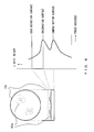
control unit 200 in response to a user press of theAF button 311 on the GUI screen. With this process, a focus value at each position in the Z direction is obtained, and a graph of characteristic data representing a relationship between a position in the Z direction and a focus value is calculated based on the obtained focus value. Then, an optimum position in the Z direction on an observation surface is calculated based on the graph of the characteristic data, and the XYZ θelectric stage 104 is moved to the position in the Z direction. Here, the focus value at each position in the Z direction is obtained as follows under the control of thefocus adjustment unit 207. Namely, the focus value is obtained by capturing an image by theimage capturing unit 105 at each position in the Z direction while moving the position of the XYZ θelectric stage 105 in the Z direction at predetermined intervals, and by calculating the focus value from a predetermined area of the captured image. Here, an area of approximately 30 percent of the captured image (however, the center position of the predetermined area is assumed to be the same as the center position of the captured image) is used as one example of the above described predetermined area. However, the predetermined area is not limited to this one. Moreover, a contrast value is used as one example of the above described focus value. However, the focus value is not limited to this one. Thus calculated graph of the characteristic data is stored in the internal memory, not illustrated, of thecontrol unit 200. -
FIG. 4 illustrates thus calculated graph of the characteristic data. The right side of this figure represents the graph of the characteristic data. Here, a horizontal axis corresponds to a focus value, whereas a vertical axis corresponds to a position of the XYZ θelectric stage 104 in the Z direction. Moreover, the left side schematically illustrates a top surface and a cross section of thecircular sample 103. Here,cells 103a being cultured are represented along with thecircular sample 103. Moreover,FIG. 4 schematically illustrates correspondences with the positions in the Z direction with dotted lines between the graph on the right side and the portion representing the cross section of thecircular sample 103 on the left side. - As represented by the graph on the right side of this figure, there are two positions having a large focus value in the Z direction. One of them is an observation surface (see the "observation surface" on the right side of this figure) , whereas the other is a bottom surface of the circular sample 103 (see the bottom surface of the sample on the right side of this figure) . Since a shorter relative distance between the XYZ θ
electric stage 104 and therevolver 105 at either of the two positions is the bottom surface of thecircular sample 103 in theinverted microscope 100, which of the two positions is the position of the observation surface (or the bottom surface of the circular sample 103) can be identified. When the position of the observation surface is identified in this way, the XYZ θelectric stage 104 moves to that position. As a result, the focus is achieved at that position. - In S3 of
FIG. 2 , the focus position of thecircular sample 103 is automatically aligned in this way. However, the focus position can be aligned manually by using the Zaxis focus handle 108. Alternatively, the focus position can be aligned by using theZ direction button 322 or the Zdirection slide bar 323 on the GUI screen. - Next, coordinates of the center position of the
circular sample 103 set on the XYZ θelectric stage 104 are calculated in S4. The coordinates of the center position calculated here are assumed to be an origin of an observation position to be obtained later (the origin on the XY plane). However, the calculation itself of the coordinates of the center position in S4 is performed by using XY coordinates possessed by the XYZ θelectric stage 104. - Such a calculation of the coordinates of the center position of the
circular sample 103 is intended for the following objectives. - 1. By setting a predetermined area recognized as a pattern image to be described later in the vicinity of the calculated coordinates of the center position, pattern detection efficiency at the time of pattern matching to be described later can be increased.
- 2. By using the calculated coordinates of the center position as the origin, an observation position can be reproduced with polar coordinates.
- If the rotational center position of the XYZ θ
electric stage 104 is the same as the center position of thecircular sample 103 when thecircular sample 103 is set on the XYZ θelectric stage 104, the center position of thecircular sample 103 is determined. However, if the rotational center position is not the same as the center position or if an electric stage that does not rotate is adopted, the coordinates of the center position of thecircular sample 103 need to be calculated. In this embodiment, the case where the rotational center position of the XYZ θelectric stage 104 and the center position of thecircular sample 103 are not the same is assumed, and the coordinates of the center position of thecircular sample 103 are calculated. -
FIG. 5 is a flowchart illustrating details of the operation (S4) for calculating the coordinates of the center position of thecircular sample 103. - As illustrated in this figure, a process for moving the XYZ θ
electric stage 104 to a particular position is initially executed in S41. This is the process executed under the control of thecontrol unit 200 in response to a user press of the centerposition calculation button 363 on the GUI screen. The move to the particular position is made to enhance an edge of an outer shape of thecircular sample 103. The particular position is a position in the Z direction (see the edge detection surface on the right side ofFIG. 4 ) where a focus value of 50 percent of a maximum focus value is obtained in the graph of the characteristic data (see the right side ofFIG. 4 ) obtained in S3 ofFIG. 2 . However, if there are a plurality of positions where the focus value of 50 percent is obtained in this case, a position located on an upper side of an observation surface (see the observation surface on the right side ofFIG. 4 ) is recognized as the particular position among the plurality of positions. Here, the particular position is assumed to have the focus value of 50 percent of the maximum focus value. However, the ratio is not limited to 50 percent. Moreover, the ratio may be arbitrarily set by a user. Otherwise, the particular position may be obtained not in this way but as follows. For example, a distance between a position of the bottom surface of thecircular sample 103 and a position of the edge detection surface is prestored in the memory, not illustrated, of thecontrol unit 200. Then, the particular position can be obtained based on the distance, and the position of the bottom surface of the circular sample 103 (see the sample bottom surface on the right side ofFIG. 4 ) identified with the graph of the characteristic data (see the right side ofFIG. 4 ) obtained in S3 ofFIG. 2 . - Upon termination of S41 of
FIG. 5 in this way, an image including an edge of the outer shape of thecircular sample 103 is captured next in S42. This capturing is performed as follows. Initially, a user moves the XYZ θelectric stage 104 in the XY direction by operating the stage control area 320 on the GUI screen while viewing a live image displayed in theimage display area 340 on the GUI screen. Then, the user presses theSNAP button 313 on the GUI screen when an area including the edge of the left end (one end) of thecircular sample 103 is displayed in theimage display area 340 as a live image. As a result, the image of the area including the edge of the left end of thecircular sample 103 is captured as a snap image under the control of thecontrol unit 200. Next, the user moves the XYZ θelectric stage 104 only in the X direction (here, the horizontal direction of thecircular sample 103 is assumed to be the X direction) by operating the stage control area 320 on the GUI screen. Then, in a similar manner, the user presses theSNAP button 313 when an area including an edge of the right end (the other end) of thecircular sample 103 is displayed in theimage display area 340 as a live image. As a result, the image of the area including the edge of the right end of thecircular sample 103 is captured as a snap image under the control of thecontrol unit 200. - The order of capturing the two images here is not limited to this one. Moreover, the user can switch the
objective lens 107 in the optical path (for example, switch to anobjective lens 107 having the lowest magnification) by operating the objectivelens control area 330 on the GUI screen so that an image of a desired area is captured. In this case, however, the sameobjective lens 107 in the optical path needs to be used to capture the two images. Alternatively, theobjective lens 107 in the optical path can be automatically switched to anobjective lens 107 having the following magnification when a user presses the centerposition calculation button 363 on the GUI screen. Namely, theobjective lens 107 in the optical path can be automatically switched to anobjective lens 107 having a magnification (for example, theobjective lens 107 having the lowest magnification) by which an image of an area suitable for edge point detection in S43 to be described later is captured. Here, the automatically switched objective lens (inserted in the optical path) can be preset based on the diameter or the like of a usedcircular sample 103, or may be arbitrarily set by a user. - Upon termination of S42 in this way, a process for detecting an edge point from the two images captured in S42 is executed under the control of the
control unit 200 in S43. -
FIG. 6 is an explanatory view of the edge point detection process executed in S43. - In this figure,
images image 501 is the image of the area including the edge of the left end of thecircular sample 103, whereas theimage 502 is the image of the area including the edge of the right end of thecircular sample 103. Theimages sample fixing member 104a for fixing thecircular sample 103 onto the XYZ θelectric stage 104 is captured. - The edge point detection is performed by filtering a captured image with a differential filter, and by using, as an edge point, a position where an absolute value of the output of the differential filter becomes large. For example, a Laplacian filter is used as the differential filter. When edge points are detected in this way, an edge point of the
circular sample 103 is further detected from among the detected edge points. In this embodiment, anedge point 501a positioned on the uppermost side and the rightmost side, and anedge point 501b positioned on the lowermost side and the rightmost side in theimage 501 of the area including the edge of the left end of thecircular sample 103 are detected as edge points of thecircular sample 103. Moreover, in theimage 502 of the area including the edge of the right end of thecircular sample 103, anedge point 502a positioned on the uppermost side and the leftmost side, and anedge point 502b positioned on the lowermost side and the leftmost side are detected as edge points of thecircular sample 103. - Upon termination of S43 of
FIG. 5 in this way, a process for calculating the coordinates of the center position of thecircular sample 103 from the detected edge points by using, for example, a method such as a least-square method or the like is executed under the control of thecontrol unit 200 in S44. -
FIG. 7 is an explanatory view of the center position coordinates calculation process executed in S44. Here, a simple processing method is described as one example. - As illustrated in
FIG. 7 , the coordinates of the center position of thecircular sample 103 are calculated from at least four edge points. Here, edge points detected as the edge points on the left end side of thecircular sample 103 are defined as 501c and 501d, whereas edge points detected as the edge points on the right end side are defined as 502c and 502d. These four edge points have a positional relationship different from the four edge points (501a, 501b, 502a and 502b) illustrated inFIG. 6 . However, in either case, the center position can be similarly calculated with the processing method described here. - In the process example, as illustrated on the left side of
FIG. 7 , the edge points 501c and 501d on the left end side are initially compared with the edge points 502c and 502d on the right end side, and edge points having the same Y coordinate are paired up. Then, all midpoints of segments respectively linking the paired edge points are detected, and a linear line (approximately linear line) X=a linking the midpoints is obtained. Next, as illustrated on the right side ofFIG. 7 , a linear line (approximately linear line) Y=b is obtained so that distances from all the edge points to the linear line X=a become equal. As a result, coordinates (a,b) of the center position of thecircular sample 103 are obtained, and a radius r of thecircular sample 103 is obtained based on the coordinates (a,b) of the center position and the edge points. - Here, the simple processing method is described. However, the process for calculating the coordinates of the center position of the
circular sample 103 is not limited to this one. For example, like a method for measuring the center position of a circle disclosed by Japanese Laid-open Patent Publication No.H07-225843 - By adopting such a processing method, the coordinates of the center position of the
circular sample 103 can be calculated even though the image of thecircular sample 103 cannot be actually captured as a circle when thecircular sample 103 is set on the XYZ θelectric stage 104. - Thus calculated coordinates of the center position of the
circular sample 103 are stored and held in the memory, not illustrated, of thecontrol unit 200. - Upon termination of S44 of
FIG. 5 in this way, the XYZ θelectric stage 104 next moves both in the XY direction and in the Z direction as follows under the control of thecontrol unit 200 in S45. Namely, the XYZ θelectric stage 104 moves in the XY direction based on the coordinates of the center position of thecircular sample 103, which are calculated in S44, so that the center position of thecircular sample 103 matches that of an image capturing range by theimage capturing unit 106. At the same time, the XYZ θelectric stage 104 moves in the Z direction to retract to the position of the observation surface (see the observation surface on the right side ofFIG. 4 ) where the focus position is aligned in the above described S3. - In S4 of
FIG. 2 (the flowchart ofFIG. 5 ) executed in this way, the edge points of thecircular sample 103 are automatically detected as described with reference toFIG. 6 and the like. However, the edge points can be manually detected. -
FIG. 8 is an explanatory view of an example of operations performed when the edge points are manually detected. - As illustrated in this figure, a
dialog 371 "Automatically calculates edge detection?" is displayed on thedisplay unit 300 in response to a user press of the centerposition calculation button 363 on the GUI screen. If the user selects "YES" in thisdialog 371 via theinput unit 400, edge points of thecircular sample 103 are automatically detected. In the meantime, if the user selects "NO", thedialog 371 is switched to adialog 372 "Click a sample edge on a live screen". Here, the user moves the XYZ θelectric stage 104 by operating the stage control area 320 on the GUI screen, and causes an area including edges of thecircular sample 103 to be displayed in theimage display area 340 on the GUI screen as a live image. Then, the user specifies (such as clicks with a mouse) a position used as an edge point of thecircular sample 103 via theinput unit 400 in the live image, the position is detected as the edge point. Moreover, a mark (a flag icon in this embodiment) is attached to the edge point that the user has specified in the live image for visual verification. The example illustrated inFIG. 8 represents that the four edge points have been specified in the live image as the edge points of thecircular sample 103. If the user selects "NEXT" in thedialog 372 via theinput unit 400 after specifying the edge points needed to calculate the coordinates of the center position of thecircular sample 103 in this way, the following operations are performed. Namely, thedialog 372 is switched to adialog 373 "Calculating the center position of the circular sample" the same time the center position coordinates calculation process (S44 ofFIG. 5 ) of thecircular sample 103 is started based on the specified edge points. If "CANCEL" is selected via theinput unit 400 when thedialog - Upon termination of S4 of
FIG. 2 in this way, whether or not thecircular sample 103 set on the XYZ θelectric stage 104 is acircular sample 103 observed for the first time is determined next in S5. This determination is performed under the control of thecontrol unit 200, for example, by causing a dialog for inquiring of a user about whether or not thecircular sample 103 is the circular sample observed for the first time to be displayed on thedisplay unit 300, and by causing the user to select "YES" or "NO" via theinput unit 400. If the user selects "YES" in this dialog, the determination results in YES and the flow goes to S6. Alternatively, if the user selects "NO" in this dialog, the determination results in "NO" and the flow goes to S11. - If the determination results in "YES" in S5, the sample ID is newly registered in S6. This new registration is performed under the control of the
control unit 200 in response to a user press of theregistration button 361 on the GUI screen. For the new registration, a dialog for accepting a sample ID of thecircular sample 103 set on the XYZ θelectric stage 104 is displayed on thedisplay unit 300. When the user inputs his or her desired sample ID in the dialog via theinput unit 400, the sample ID is displayed in a sampleID display field 364 on the GUI screen and stored in the position reproductioninformation storage unit 208. -
FIG. 9 is an explanatory view of the sample ID new registration performed in S6. As illustrated in this figure, when a user presses theregistration button 361 on the GUI screen, thedialog 376 for accepting a sample ID input from a user is displayed on thedisplay unit 300. This embodiment assumes to accept a sample ID as a file name.FIG. 9 illustrates an example where "test1. xxx" is input as a sample ID. Then, the user selects "SAVE (S)" in thedialog 376 via theinput unit 400, whereby the input sample ID is displayed in the sampleID display field 364 on the GUI screen and stored in the position reproductioninformation storage unit 208. In contrast, if the user selects "CANCEL" in thedialog 376 via theinput unit 400, the sample ID new registration at this time point is canceled. After "SAVE (S)" or "CANCEL" is selected in thedialog 376, thedialog 376 is not displayed on thedisplay unit 300 any more. - This embodiment assumes that a user inputs a sample ID to be newly registered. However, the sample ID to be newly registered may be automatically input. In this case, the sample ID to be newly registered automatically can be set, for example, as "user login ID name - date - total number of new registrations. xxx". Alternatively, whether the sample ID to be newly registered is either input by a user or automatically input may be arbitrarily changed by a user.
- Upon termination of S6 of
FIG. 2 in this way, a reference pattern image (one example of the above described first pattern image) is next obtained under the control of thecontrol unit 200 in S7. The reference pattern image obtained here is an image of a predetermined area in the image of the bottom surface of thecircular sample 103, and obtained as follows. Initially, the XYZ θelectric stage 104 moves in the XY direction based on the coordinates of the center position (one example of the coordinates of the above described first center position) of thecircular sample 103, which are calculated in the above described S4, so that the center position of thecircular sample 103 matches that of the image capturing area by theimage capturing unit 106. The XYZ θelectric stage 104 moves also in the Z direction to reach the position of the bottom surface of the circular sample 103(see the sample bottom surface on the right side ofFIG. 4 ) identified with the graph of the characteristic data (see the right side ofFIG. 4 ) obtained in S3. As a result, the focus position is aligned with the position of the bottom surface of thecircular sample 13. Moreover, theobjective lens 107 is switched as needed so that anobjective lens 107 having a predetermined magnification (such as the lowest magnification) is inserted in the optical path. Then, an image, having a center position that is the center position of thecircular sample 103, of the bottom surface of thecircular sample 103 is obtained by image capturing of theimage capturing unit 106. - The reason why the focus position is aligned not with the position of the observation surface to be actually observed but with the position of the bottom surface of the
circular sample 103 is as follows. Supposing that the image is obtained by aligning the focus position with the position of the observation surface to be actually observed, a pattern of the obtained image can possibly vary with time due to a morphological change or growth of live cells to be observed. Accordingly, such an image is not suitable as an image used for pattern matching to be performed later. - Additionally, when the image of the bottom surface of the
circular sample 103 is obtained, image capturing is performed under image capturing conditions different from those used when an image of the observation surface to be actually observed is obtained. The reason is to more clearly capture an image of a distinctive pattern, a flaw or the like on the bottom surface of thecircular sample 103. Areas of the captured image portions (areas of the image) are used for the pattern matching to be performed later. For example, even though image capturing conditions according to a phase difference observation method, set as an observation method, are set as image capturing conditions when an image on an observation surface is obtained, the observation method is changed to a bright-field observation method when the image of the bottom surface of thecircular sample 103 is obtained. As a result, the image capturing conditions are changed to those according to the bright-field observation method. Alternatively, for example, even though image capturing conditions according to a differential interference observation method, set as an observation method, are set as image capturing conditions when an image on an observation surface is obtained, the observation method is changed to a phase difference observation method when the image of the bottom surface of thecircular sample 103 is obtained. As a result, the image capturing conditions are changed to those according to the phase difference observation method. Such a change of an observation method (including image capturing conditions) is automatically performed. However, for example, a user may arbitrarily change the observation method. After the image of the bottom surface of thecircular sample 103 is obtained, the observation method (including the image capturing conditions) is restored to an observation method used when an image of an observation surface to be actually observed is obtained. - When the image of the bottom surface of the
circular sample 103 is obtained in this way, an image of a predetermined area in the image is next recognized and obtained as a reference pattern image. Here, the predetermined area is determined based on the image capturing area of theimage capturing unit 106, and the coordinates of the center position of thecircular sample 103, which are calculated in S4. This embodiment assumes that the predetermined area is an area within a circle having a center that is the center of the image, and having a radius that is the shortest length from the center to an end of the image in the obtained image of the bottom surface of thecircular sample 103. -
FIG. 10 illustrates one example of the image of the predetermined area, which is recognized as a reference pattern image, from the image of the bottom surface of thecircular sample 103. - As illustrated in this figure, the image of the predetermined area, which is recognized as the reference pattern image from the
image 511 of the bottom surface of thecircular sample 103, is the following image. Namely, the image of the predetermined area is an image of thearea 511b within the circle having a center that is thecenter 511a of theimage 511 of the bottom surface, and having a radius that is the shortest length from thecenter 511a to an end of the image (the length from thecenter 511a to the upper or lower end of theimage 511 in this example). - In the example illustrated in
FIG. 10 , the diameter of thearea 511b corresponds to the number of vertical pixels of the CCD of theimage capturing unit 106. Moreover, acenter 103b of thecircular sample 103 corresponds to thecenter 511a of theimage 511. Additionally, the image of thearea 511b within the circle also includes apattern 511c where an image of a flaw located on the bottom surface of thecircular sample 103 is captured. - The reason why such an image of the area within the circle is recognized as a reference pattern image is as follows. If a rotational shift of the
circular sample 103 occurs when thecircular sample 103 is set on the XYZ θelectric stage 104 at the second or subsequent observation, a pattern included outside the area within the circle, namely, the pattern included in the area outside the circle moves outside the image of the bottom surface of thecircular sample 103, which is obtained at the second or subsequent observation. Accordingly, there is a possibility that the pattern matching to be described later cannot be performed. - Note that a user may arbitrarily set the image of the predetermined area, which is recognized as the reference pattern image from the image of the bottom surface of the
circular sample 103. However, the predetermined area is defined as an area within a circle having a center that is the center of the image of the bottom surface of thecircular sample 103, and having a radius that is shorter than the shortest length from the center to an end of the image in order to eliminate the above described possibility. - When the reference pattern image is obtained in this way, the following image and information are stored in the position reproduction
information storage unit 208 in association with the sample ID newly registered in S6. The image and the information are the reference pattern image, and the information such as image capturing conditions, the position of the XYZ θelectric stage 104 in the Z direction, and other items of information when the reference pattern image is captured. Here, the image capturing conditions used when the reference pattern image is captured are image capturing conditions used also when the image of the bottom surface of thecircular sample 103 including the reference pattern image is captured. Moreover, the image capturing conditions include the magnification of theobjective lens 107, an observation method, an exposure time, an image size and the like. - The reference pattern image, and the information such as the image capturing conditions, the position in the Z direction, and the like, which are stored here, are used for operations performed later at the second or subsequent observation.
- Upon termination of S7 of
FIG. 2 in this way, an image at an observation position to be observed actually in thecircular sample 103 is obtained, and at the same time, also the coordinates of the observation position, image capturing conditions, and the like used when the image is obtained are obtained. However, the obtained XY coordinates of the observation position are represented not with a coordinate system possessed by the XYZ θelectric stage 104 but with a coordinate system using the coordinates of the center position of thecircular sample 103, which are calculated in the above described S4, as an origin. Namely, the origin of the XY coordinates is changed from the origin possessed by the XYZ θelectric stage 104 to the center position of thecircular sample 103, which is calculated in the above described S4, thereby representing the XY coordinates of the observation position. -
FIG. 11 is an explanatory view of such a change of the origin. - As illustrated in this figure, the origin of the XY coordinates is changed from an
origin 104b in the coordinate system possessed by the XYZ θelectric stage 104 to thecenter position 103b of thecircular sample 103. Here, in the coordinate system possessed by the XYZ θelectric stage 104, XY coordinates of thecenter position 103b of thecircular sample 103 are (Δx, Δy). - The reason why the origin of the XY coordinates is changed in this way is as follows. If the
circular sample 103 is repeatedly removed/set, the center of thecircular sample 103 cannot be always set at the same position on the XYZ θelectric stage 104. Accordingly, it is more convenient to use relative coordinates having an origin that is the center of thecircular sample 103 as the XY coordinates of an observation position in order to reproduce the observation position stored at the first observation at the second or subsequent observation. - Additionally, at that time, a rotational shift of the
circular sample 103 set on the XYZ θelectric stage 104 is also taken into account at the second or subsequent observation, and polar coordinates having an origin that is the center of thecircular sample 103 are used as relative coordinates. -
FIG. 12 illustrates an example where the XY coordinates of an observation position are represented with polar coordinates. - In the example illustrated in
FIG. 12 , the XY coordinates of an observation position P are represented as (R1, θ 1) by using a polar coordinate system having an origin O that is thecenter position 103b of thecircular sample 103. Here, R1 is a distance between the origin O and the observation position P, andθ 1 is an angle formed between a horizontal line (a linear line in the horizontal direction ofFIG. 12 ) that passes through the origin O and a segment OP. The coordinates of the observation position P can be represented also as (R1cos θ 1, R1sin θ 1) with an XY coordinate system having the origin O that is thecenter position 103b of thecircular sample 103. - By representing and storing the XY coordinates of an observation position with polar coordinates as described above, the observation position can be reproduced based on the coordinates of the observation position, and the coordinates of the center position of the
circular sample 103, which are obtained at the second or subsequent observation when the observation position is reproduced at the second or subsequent observation. - In S8 of
FIG. 2 , an image or the like of the observation position is specifically obtained as follows. - Initially, a user operates the stage control area 320 or the objective
lens control area 330 on the GUI screen as needed so that a desired observation area is displayed in theimage display area 340 while verifying a live image of thecircular sample 103 displayed in theimage display area 340 on the GUI screen. When the desired observation area is displayed in theimage display area 340, the user presses theSNAP button 313 on the GUI screen. As a result, under the control of thecontrol unit 200, an image of the area displayed in theimage display area 340 is obtained with image capturing performed by theimage capturing unit 106, and the captured image is stored in the position reproductioninformation storage unit 208 in association with the sample ID newly registered in S6 along with information such as coordinates, image capturing conditions, and the like at the time of image capturing. - The coordinates at the time of image capturing are coordinates of the center position of an obtained image, and represented with relative coordinates as described above. Moreover, the image capturing conditions at the time of image capturing include the magnification of the
objective lens 107, an observation method, an exposure time, an image size and the like used at the time of image capturing. - Additionally, the information such as the coordinates, the image capturing conditions, and the like at the time of image capturing are displayed as a list in the
list area 365 on the GUI screen. Moreover, the position (corresponding to the center position of an obtained image) of thecircular sample 103, at which the obtained image is captured, is schematically displayed in the entiremap image area 350 on the GUI screen so that a user can verify that position. -
FIG. 13 illustrates one example of the GUI screen when an image at an observation position is obtained twice in this way. - As illustrated in this figure, coordinates and image capturing conditions used when each image at each observation position is obtained are displayed as a list in the
list area 365, and at the same time, each observation position is schematically displayed as a flag icon in the entiremap image area 350. - In the
list area 365, "X", "Y" and "Z" indicate the coordinates of each observation position. As described above, XY coordinates of each observation position are represented and stored with polar coordinates. However, the coordinates of each observation position are represented and displayed with XY coordinates when being displayed in thelist area 365. Naturally, the coordinates represented with the polar coordinates can be displayed in thelist area 365 unchanged. Moreover, in thelist area 365, "M" indicates the magnification of anobjective lens 107, and "OM" indicates an observation method. Such items displayed in thelist area 365 are not limited to these ones. A user may arbitrarily select items. - Upon termination of S8 of
FIG. 2 in this way, the user removes thecircular sample 103 from the XYZ θelectric stage 104 and again keeps thecircular sample 103 in a particular culture environment such as an incubator or the like in S9. - Next, in S10, whether or not to transfer to an observation of another
circular sample 103 is determined. This determination is performed with a predetermined operation that the user performs via theinput unit 400. For example, if the user performs the operation for transferring to an observation of anothercircular sample 103, the determination results in "YES" and the flow goes back to S2. In contrast, if the user performs an operation for terminating this process (the operation for not transferring to the observation of another circular sample 103), the determination results in "NO" and the process is terminated. - By performing the operations for the first observation in this way, the following image and information are stored in the position reproduction
information storage unit 208 in association with the sample ID newly registered in S6. The image and the information are the reference pattern image obtained in S7, information such as the image capturing conditions, the position of the XYZ θelectric stage 104 in the Z direction when the reference pattern image is captured, the image at the observation position, which is obtained in S8, and information such as coordinates of the observation position, the image capturing conditions and other items of information when the image is captured. -
FIG. 14 illustrates a folder structure of images and information stored in the position reproductioninformation storage unit 208 in association with a newly registered sample ID. - As illustrated in
FIG. 14 , the folder structure is composed of a hierarchical structure of four layers from the first highest layer to the fourth lowest layer. A folder of the first layer is a sample ID folder provided for each newly registered sample ID. Here, the sample ID folder includes a sample ID (a file having a file name input as a sample ID at the time of new registration) newly registered in S6 ofFIG. 2 .FIG. 14 illustrates the sample ID folder provided for one newly registered sample ID as acircular sample 1 folder. Each sample ID folder includes a reference pattern data folder and a sample reproduction position information folder as folders of the second layer. Here, the reference pattern data folder includes the reference pattern image obtained in S7 ofFIG. 2 , and information such as image capturing conditions, the position of the XYZ θelectric stage 104 in the Z direction, and other items of information when the reference pattern image is captured. Each sample reproduction position information folder includes an observation position folder provided for each observation position as a folder of the third layer. Here, each observation position folder includes information such as the coordinates of the observation position, image capturing conditions and the like when the image at the observation position, which is obtained in S8, is captured. InFIG. 14 , the observation position folders respectively provided for theobservation position 1, theobservation position 2 and theobservation position 3 are represented as anobservation position 1 folder, anobservation position 2 folder and anobservation position 3 folder. Each of the observation position folders includes an observation image folder provided for each observation as a folder of the fourth layer. In this figure, the observation image folders respectively provided for the first, the second and the third observations are represented as a first folder, a second folder and a third folder, respectively. Here, the first folder includes the image at the observation position, which is obtained in S8. - The folder structure of images and information stored in the position reproduction
information storage unit 208 in association with a newly registered sample ID is not limited to that illustrated inFIG. 14 . - Operations performed at the second or subsequent observation are described next.
- With these operations, after S1 of
FIG. 2 is performed similarly to the operations performed at the first observation, or after the determination of S10 results in "YES", S2 to S5 are performed similarly to the operations performed at the first observation. However, thecircular sample 103 set on the XYZ θelectric stage 104 at this time in S2 is acircular sample 2 used in the second or subsequent observation. - Then, the user selects "NO" via the
input unit 400 in the above described dialog for inquiring whether or not thecircular sample 103 set on the XYZ θelectric stage 104 is a circular sample to be observed for the first time, whereby the determination of S5 results in "NO". Then, the flow goes to S11. - In S11, the following information is read from the position reproduction information storage unit 208 (the reference pattern data folder of
FIG. 14 ). The information is information such as the image capturing conditions, the position of the XYZ θelectric stage 104 in the Z direction, and the like when the reference pattern image obtained at the first observation of thecircular sample 103 set on the XYZ θelectric stage 104 is captured. Then, the image capturing conditions, the position of the XYZ θelectric stage 104 in the Z direction, and other items of information when the reference pattern image is captured are reproduced on themicroscope 100 based on the information. Moreover, the reference pattern image obtained at the first observation is read from the position reproduction information storage unit 208 (the reference pattern data folder ofFIG. 14 ) and stored in the pattern storage unit 112. These operations are performed under the control of thecontrol unit 200 in response to an input of the sample ID of thecircular sample 103 set on the XYZ θelectric stage 104 via theinput unit 400 with a user press of theread button 362 on the GUI screen. The operation that the user performs for inputting the sample ID of thecircular sample 103 is performed as follows. -
FIG. 15 illustrates a dialog displayed on thedisplay unit 300 when the user inputs the sample ID of thecircular sample 103. - When the user presses the
read button 362 on the GUI screen, thedialog 377 for inputting a sample ID is displayed under the control of thecontrol unit 200 in response to the user press as illustrated in this figure. In thedialog 377, all sample IDs read from the position reproductioninformation storage unit 208 are displayed as a list of sample IDs registered up to this point. In the example illustrated in this figure, three sample IDs such as "test1. xxx", "test2.xxx" and "test3.xxx" are displayed as sample IDs. Then, the user selects the sample ID of thecircular sample 103 set on the XYZ θelectric stage 104 with theinput unit 400 from among the sample IDs displayed as the list. Alternatively, the user may directly input the sample ID and select "OPEN (O)" in thedialog 377. In this way, the sample ID is input. Moreover, the sample ID input at this time is displayed in the sampleID display field 364. In contrast, if the user selects "CANCEL" in thedialog 377 via theinput unit 400, the input of the sample ID at this time point is canceled. After "OPEN (O)" or "CANCEL" in thedialog 377 is selected, thedialog 377 is not displayed on thedisplay unit 300 any more. - If corresponding image capturing conditions, position in the Z direction, and the like cannot be reproduced according to the input sample ID in S11 of
FIG. 2 , an error message may be displayed on thedisplay unit 300 under the control of thecontrol unit 200. Also in this case, a dialog for inquiring of the user about whether or not to newly register a sample ID may be displayed, and the flow may go to S6 if "YES" is selected in this dialog. - Upon termination of S11 in this way, a pattern image (one example of the above described second pattern image) for which pattern matching with the reference pattern image read in the above described S11 is performed is obtained next under the control of the
control unit 200 in S12. Specifically, the XYZ θelectric stage 104 initially moves in the XY direction as follows. Namely, the XYZ θelectric stage 104 moves in the XY direction based on the coordinates of the center position of thecircular sample 103, which are calculated in the above described S4 for thecircular sample 103 set on the XYZ θelectric stage 104, so that the center position of thecircular sample 103 matches that of the image capturing area of theimage capturing unit 106. In the Z direction, the XYZ θelectric stage 104 has already moved to the position when the reference pattern image is captured in the above described S11. With image capturing by theimage capturing unit 106, the image, having the center position that is the center position of thecircular sample 103, of the bottom surface of thecircular sample 103 is obtained. - When the image of the bottom surface of the
circular sample 103 is obtained in this way, an image of a predetermined area in the image of the bottom surface is recognized and obtained as a pattern image similarly to the case of obtaining the reference pattern image. Here, also the predetermined area is determined based on the image capturing area of theimage capturing unit 106, and the coordinates of the center position of thecircular sample 103, which are calculated in the above described S4. In this embodiment, the predetermined area is assumed to be an area within a circle having a center that is the center of the circle, and having a radius that is the shortest length from the center to an end of the image in the obtained image of the bottom surface of thecircular sample 103. As a result, the size of the pattern image and that of the reference pattern image become equal. Thus obtained pattern image is stored in thepattern storage unit 203. - Upon termination of S12 in this way, pattern matching is performed under the control of the
control unit 200 between the reference pattern image stored in thepattern storage unit 203 in the above described S11 and the pattern image stored in thepattern storage unit 203 in the above described S12. Then, a rotational shift angle (a rotational shift amount) between the reference pattern image and the pattern image is calculated. Here, the calculation of the rotational shift angle using the pattern matching can be performed, for example, by using a known technique such as an affine transform or the like. -
FIG. 16 illustrates an example of calculating a rotational shift angle by using pattern matching. - The example illustrated in this figure is a simple calculation example of calculating the rotational shift angle by performing pattern matching with a method for detecting a
focused area 522b from apattern image 522a, and for detecting thefocused area 522b from areference pattern image 521a. - In this figure, an
image 521 represents an image of the bottom surface of thecircular sample 103 including areference pattern image 521a when the above described S7 is executed at the first observation for thecircular sample 103 set on the XYZ θelectric stage 104. Moreover, apoint 521b represents the center position of thereference pattern image 521a (also the center position of the image 521). - Additionally, an
image 522 represents the image of the bottom surface of thecircular sample 103 including thepattern image 522a when the above described S12 is executed for thecircular sample 103 set on the XYZ θelectric stage 104. Moreover, apoint 522c represents the center position of thepattern image 522a (also the center position of the image 522) . - Detection of the focused
area 522b from thepattern image 522a is performed, for example, by detecting the largest area as an aggregation of pixels having a low brightness value from thepattern image 522a. In this case, a brightness value threshold value is preset, and an aggregation of pixels having a brightness value smaller than the threshold value is detected from thepattern image 522a, and an area having the largest number of pixels included in the aggregation is detected as a focused area. In this case, a user may arbitrarily change the brightness value threshold value. - Detection of the focused
area 522b from thereference pattern image 521a is performed, for example, as follows. A relative distance between thecenter position 522c and thefocused area 522b of thepattern image 522a can be calculated. Accordingly, thefocused area 522b is detected by rotating thefocused area 522b about thecenter position 522c, and by detecting an area where all characteristic points (such as edge coordinates, and the like) of the focusedarea 522b match is detected from thereference pattern image 521a. - Then, a rotational angle formed when the area where all the characteristic points of the focused
area 522b match is detected from thereference pattern image 521a is calculated as a rotational shift angle between thereference pattern image 521a and thepattern image 522a. - As described above, in this embodiment, the pattern matching between the
reference pattern image 521a and thefocused area 522b of thepattern image 522a is performed as pattern matching performed between thereference pattern image 521a and thepattern image 522a. However, the pattern matching is not limited to this one. - Upon termination of S13 of
FIG. 2 in this way, the XYZ θelectric stage 104 rotates in the θ direction under the control of thecontrol unit 200 so that the rotational shift angle calculated in S13 becomes 0 degrees. As a result, the rotational shift of thecircular sample 103 between the first observation and the second or subsequent observation is corrected. - Next, in S15, coordinates of each observation position, and image capturing conditions at each observation position, which are obtained for the
circular sample 103 having the sample ID input in S11, are read from the position reproduction information storage unit 208 (each observation position folder ofFIG. 14 ) under the control of thecontrol unit 200. Then, each observation position is schematically displayed as a flag icon in the entiremap image area 350 on the GUI screen based on the read coordinates of each observation position. Moreover, the read image capturing conditions at each observation position are displayed in thelist area 365 on the GUI screen. - Then, in S16, an image is captured at each observation position by the
image capturing unit 106 based on the coordinates and the image capturing conditions of each observation position, which are read from the position reproductioninformation storage unit 208 in S15, under the control of thecontrol unit 200, so that the image at each observation position is automatically obtained. In this case, based on corresponding coordinates and image capturing conditions, the XYZ θelectric stage 104 moves to the coordinates of each observation position, and at the same time, the image capturing conditions are reproduced on themicroscope 100. Then, an image is captured by theimage capturing unit 106. - The image obtained at each observation position is stored in the position reproduction information storage unit 208 (the observation image folder of
FIG. 14 ) as an image obtained at the second or subsequent observation in association with the sample ID input in S11. - Upon termination of S16 in this way, the flow goes back to S9, and these operations are similarly repeated until the determination of S10 results in "NO".
- As described above, with the microscope apparatus according to this embodiment, a rotational shift of the
circular sample 103, which can possibly occur between the first observation and the second or subsequent observation when thecircular sample 103 is observed a plurality of times, can be corrected. Accordingly, an observation position at the first observation can be reproduced with high accuracy also at the second or subsequent observation, thereby enabling an accurate temporal observation. - Note that the microscope apparatus according to this embodiment can be modified in a variety of ways.
- For example, the following modification can be performed as a modification example 1.
- In this modification example, the rotational shift correction performed in S14 of
FIG. 2 is performed by rotating not the XYZ θelectric stage 104 but theimage capturing unit 106. -
FIG. 17 schematically illustrates an entire configuration of a microscope apparatus according to this modification example. - As illustrated in this figure, the
microscope 100 further includes arotation unit 110 in the microscope apparatus according to this modification example. Therotation unit 110 rotates theimage capturing unit 106 about an optical axis that passes through the center of an image capturing surface as a rotational axis under the control of thecontrol unit 200. - In the microscope apparatus according to this modification example, the
rotation unit 110 rotates theimage capturing unit 106 under the control of thecontrol unit 200 in S14 ofFIG. 2 so that the rotational shift angle calculated in S13 becomes 0 degrees. As a result, the rotational shift between an image of thecircular sample 103, which is obtained at the first observation, and an image of thecircular sample 103, which is obtained at the second or subsequent observation, is corrected. - In this modification example, the
image capturing unit 106 is automatically rotated in this way. However, theimage capturing unit 106 may be manually rotated. In this case, therotation unit 110 is configured to have a manual handle, which a user operates to rotate theimage capturing unit 106. Moreover, the rotational shift angle calculated in S13 ofFIG. 2 is displayed on the display unit 300 (the rotational shift angle may be displayed on the GUI screen), and at the same time, the displayed rotational shift angle may be varied according to the rotational angle of theimage capturing unit 106. In this way, the user operates the manual handle of therotation unit 110 so that that the rotational shift angle displayed on thedisplay unit 300 becomes 0 degrees, thereby enabling the rotational shift of the image of thecircular sample 103 to be corrected. - As described above, according to this modification example, an image of the
circular sample 103, which has no rotational shift between the first observation and the second or subsequent observation, can be obtained and displayed on thedisplay unit 300, and effects similar to those of the above described embodiment can be achieved. - Additionally, the microscope apparatus according to this embodiment can be modified, for example, as follows as a modification example 2.
- In this modification example, the rotational shift correction in S14 of
FIG. 2 is performed by rotating not the XYZ θelectric stage 104 but an image displayed in theimage display area 340 on the GUI screen (the image displayed on the display unit 300). -
FIG. 18 schematically illustrates an entire configuration of a microscope apparatus according to this modification example. - As illustrated in this figure, in the microscope apparatus according to this modification example, the
control unit 200 further includes a displayimage rotation unit 209. The displayimage rotation unit 209 rotates an image displayed in theimage display area 340 on the GUI screen about the center of the image as a rotational center. - With the microscope apparatus according to this modification example, the display
image rotation unit 209 rotates an image of thecircular sample 103, which is displayed in theimage display area 340 on the GUI screen, under the control of thecontrol unit 200 so that the rotational shift angle calculated in S13 becomes 0 degrees. As a result, a rotational shift between an image of thecircular sample 103 displayed on thedisplay unit 300 at the first observation and an image of thecircular sample 103 displayed on thedisplay unit 300 at the second or subsequent observation is corrected. - The rotation of an image by the display
image rotation unit 209 can be performed with a known image process such as an affine transform or the like. - As described above, according to this modification example, an image of a
circular sample 103, which has no rotational shift between the first observation and the second or subsequent observation, can be displayed on thedisplay unit 300 similarly to the modification example 1. As a result, effects similar to those of the above described embodiment can be achieved. - Additionally, the microscope apparatus according to this embodiment can be also modified, for example, as follows as a modification example 3.
- In this modification example, an observation position can be added or deleted at the second or subsequent observation. As a result, at the second or subsequent observation, a user can add a new observation position, or deletes an observation position determined to be unnecessary.
-
FIG. 19 is a flowchart illustrating operations according to this modification example. - As illustrated in this figure, the operations according to this modification example further include S21 and S22 between S16 and S9.
- In S21, whether either to add or to delete an observation position is determined. This determination is performed under the control of the
control unit 200, for example, by causing a dialog for inquiring of a user about whether either to add or to delete an observation position to be displayed on thedisplay unit 300, and by causing the user to select "YES" or "NO" in the dialog via theinput unit 400. If the user selects "YES", the determination results in "YES" and the flow goes to S22. If the user selects "NO", the determination results in "NO" and the flow goes to S9. - In S22, the observation position is added or deleted. This addition/deletion is performed under the control of the
control unit 200, for example, by displaying a dialog for inquiring of the user about whether either to add or to delete the observation position to be displayed on thedisplay unit 300, and by causing the user to select "ADD" or "DELETE" in the dialog via theinput unit 400. - If the user selects "ADD", an image is obtained at the added observation position, and coordinates of the observation position, image capturing conditions and the like used when the image is obtained are obtained similarly to S8 under the control of the
control unit 200. As a result, an image and the like also for the observation position added here can be automatically obtained at subsequent observations. - If the user selects "DELETE", an observation position to be deleted is selected under the control of the
control unit 200. This is performed by causing the user to select a flag icon of the observation position to be deleted from among flag icons displayed in the entiremap image area 350 on the GUI screen via theinput unit 400. When the observation position to be deleted is selected in this way, the selected observation position is invalidated, and its image and the like are not automatically obtained at subsequent observations. - As described above, according to this modification example, a user can easily add or delete an observation position at the second or subsequent observation.
- The microscope apparatus according to this embodiment can be modified, for example, as follows as a modification example 4.
- In this modification example, processes are executed by excluding an area (also referred to as an unnecessary pattern area) of a portion, not obtained from the
circular sample 103, from the pattern image obtained in S12 in S13 ofFIG. 2 . As a result, the area of the portion, not obtained from thecircular sample 103, is not detected as a focused area when the focused area (seeFIG. 16 ) is detected from the pattern image in S13. The area of the portion, not obtained from thecircular sample 103, is, for example, an area of a portion caused by an influence of dust in an optical system or a pixel fault or the like of theimage capturing unit 106. - With operations according to this modification example, in S13, before a focused area is detected from a pattern image, the XYZ θ
electric stage 104 is initially rotated in the θ direction under the control of thecontrol unit 200 while a live image of thecircular sample 103 is being captured by theimage capturing unit 106. At this time, an area that does not rotate with the rotation of the XYZ θelectric stage 104 is detected from the live image, and the detected area is recognized as an area of a portion that is not obtained from thecircular sample 103. -
FIG. 20 is an explanatory view of the area detection performed in this way. - An
image 523 illustrated on the upper side of this figure is a live image of thecircular sample 103, which is captured by theimage capturing unit 106 before the XYZ θelectric stage 104 is rotated. Thelive image 523 is assumed to include apartial area 523a corresponding to a portion of thecircular sample 103, and apartial area 523b that is an area where an image of dust in the optical system is captured. - The position of the XYZ θ
electric stage 104, the image capturing conditions, and the like when thislive image 523 is captured are the same as those when the pattern image is obtained in S12 ofFIG. 2 , and acenter position 523c of thelive image 523 corresponds to the center position of thecircular sample 103. - An image 523' illustrated on the lower side of
FIG. 20 is a live image of thecircular sample 103, which is captured by theimage capturing unit 106 after the XYZ θelectric stage 104 is rotated. Here,partial areas 523a' and 523b' within the live image 523' are the twopartial areas electric stage 104 is rotated. - As described above, the
partial area 523a corresponding to the portion of thecircular sample 103 rotates with the rotation of the XYZ θelectric stage 104, whereas thepartial area 523b that is the area where the image of the dust in the optical system is captured does not rotate with the rotation of the XYZ θelectric stage 104. Accordingly, in such a case, thepartial area 523 is detected as an area that does not rotate with the rotation of the XYZ θstage 104, and this area is recognized as an area of a portion that is not obtained from thecircular sample 103. - When the area that does not rotate with the rotation of the XYZ θ
electric stage 104 is recognized as an area of a portion that is not obtained from thecircular sample 103 in this way, the processes are executed by excluding this area from the pattern image when detecting a focused area. As a result, the area recognized as the area of the portion that is not obtained from thecircular sample 103 is not detected as a focused area any more. - As described above, according to this modification example, a suitable area as a focused area can be detected from a pattern image without being exerted by an influence of dust in the optical system, a pixel flaw or the like of the
image capturing unit 106. - In this modification example, the area recognized as the area of the portion that is not obtained from the
circular sample 103 can be displayed, for example, in different color for the sake of quick identification when the image is thereafter displayed in theimage display area 340 on the GUI screen. - Additionally, in this modification example, an area that does not rotate with the rotation of the XYZ θ
electric stage 104 is detected. However, theimage capturing unit 106 may be rotated instead of rotating the XYZ θelectric stage 104. In this case, for example, the configuration applied to the modification example 1 is combined, and the area that does not rotate with the rotation of theimage capturing unit 106 is detected from a live image. As a result, at least an area caused by an influence of a pixel flaw of theimage capturing unit 106 can be prevented from being detected as a focused area. Alternatively, a user may manually rotate a circular sample instead of rotating the XYZ θelectric stage 104. In this case, an area that does not rotate with the user manual rotation of the circular sample is detected from a live image. - Furthermore, the microscope apparatus according to this embodiment can be modified, for example, as follows as a modification example 5.
- In S13 of
FIG. 2 , pattern matching is performed by detecting the focused area (522b ofFIG. 16 ), which is detected from the pattern image (522a ofFIG. 16 ), from the reference pattern image (521a ofFIG. 16 ) as described with reference toFIG. 16 . In contrast, in this modification example, pattern matching is performed by detecting a pattern image itself from a reference pattern image. -
FIG. 21 illustrates an example of calculating a rotational shift angle with the pattern matching according to this modification example. - The example illustrated in this figure is a simple calculation example of calculating the rotational shift angle by performing pattern matching with a method for detecting a
pattern image 525a from areference pattern image 524a. - In this figure, an
image 524 represents an image of the bottom surface of thecircular sample 103 including thereference pattern image 524a when the above described S7 is executed at the first observation for thecircular sample 103 set on the XYZ θelectric stage 104. Moreover, apoint 524b represents the center position (also the center position of the image 524) of thereference pattern image 524a. - Additionally, an
image 525 represents an image of the bottom surface of thecircular sample 103 including thepattern image 525a when the above described S12 is executed for thecircular sample 103 set on the XYZ θelectric stage 104. Moreover, apoint 525b represents the center position (also the center position of the image 525) of thepattern image 525a. - Detection of the
pattern image 525a from thereference pattern image 524a is performed, for example, as follows. The detection is performed by rotating thepattern image 525a about thecenter position 525b, and by detecting that all character points (such as edge coordinates and the like) of thepattern image 525a match thereference pattern image 524a. - Then, a rotational angle when all the character points match are detected is calculated as a rotational shift angle between the
reference pattern image 524a and thepattern image 525a. - As described above, according to this modification example, the number of characteristic points compared between a reference pattern image and a pattern image increases, whereby pattern matching with higher accuracy can be performed, and a more accurate rotational shift angle can be calculated.
- Additionally, the above described modification examples 1 to 5 can be combined and applied in the microscope apparatus according to this embodiment.
- Furthermore, in the microscope apparatus according to this embodiment, a culture dish of a biological system is used as the
circular sample 103. However, for example, a disc, a circular substrate or the like of an industrial system can be used. - Still further, in the microscope apparatus according to this embodiment, a microscope such as a digital microscope, a time lapse observation microscope or the like is applicable as the
microscope 100. - Up to this point, the embodiment according to the present invention has been described. However, the present invention is not limited to the above described embodiment, and various improvements and modifications can be performed within a scope that does not depart from the gist of the present invention.
- As described above, according to the present invention, an observation position of a circular sample can be reproduced with high accuracy.
Claims (15)
- A microscope apparatus, comprising:an image capturing unit (106) for capturing an observation image;a center position calculation unit (201) for calculating coordinates of a center position of a circular sample based on the image of the circular sample, which is obtained by the image capturing unit (106);a recognition unit (202) for recognizing a pattern image of a predetermined area based on the coordinates of the center position, which are calculated by the center position calculation unit (201), from the image of the circular sample, which is obtained by the image capturing unit (106);a storage unit (203) for storing the pattern image recognized by the recognition unit (202);a rotational shift angle calculation unit (204) for calculating a rotational shift angle between a first pattern image recognized by the recognition unit (202) from an image of the circular sample, which is obtained by the image capturing unit (106) in a first period, and a second pattern image recognized by the recognition unit (202) from an image of the circular sample, which is obtained by the image capturing unit (106) in a second period later than the first period; anda position reproduction unit (205) for correcting a rotational shift of the circular sample based on the rotational shift angle calculated by the rotational shift angle calculation unit (204), and for reproducing a position of the circular sample in the first period.
- The microscope apparatus according to claim 1, wherein
the center position calculation unit (201) detects a plurality of edge points of the circular sample from the image of the circular sample, which is obtained by the image capturing unit (106), and calculates the coordinates of the center position of the circular sample based on the plurality of edge points. - The microscope apparatus according to claim 1, wherein
the center position calculation unit (201) calculates the coordinates of the center position of the circular sample based on a plurality of edge points of the circular sample, which are obtained with a manual operation from the image of the circular sample, which is obtained by the image capturing unit (106). - The microscope apparatus according to claim 2, wherein
the center position calculation unit (201) makes an arc approximation by using the plurality of edge points, and calculates the coordinates of the center position of the circular sample. - The microscope apparatus according to claim 1, wherein
the rotational shift angle calculation unit (204) calculates a rotational shift angle between the first pattern image and the second pattern image by performing pattern matching. - The microscope apparatus according to claim 1, wherein
the rotational shift angle calculation unit (204) detects a pattern image of a particular area from the second pattern image under a predetermined condition, rotates the pattern image of the particular area about an image center of the second pattern image as a rotational center, and calculates the rotational shift angle between the first pattern image and the second pattern image from a rotational angle of the pattern image of the particular area when a same pattern image as the pattern image of the particular area is detected from the first pattern image. - The microscope apparatus according to claim 1, wherein
the predetermined area is determined based on an image capturing area of the image capturing unit (106), and the coordinates of the center position, which are calculated by the center position calculation unit (201). - The microscope apparatus according to claim 1, wherein
the position reproduction unit (205) corrects the rotational shift of the circular sample by rotating the circular sample with the use of the coordinates of the center position, which are calculated by the center position calculation unit (201), as an origin based on the rotational shift angle calculated by the rotational shift angle calculation unit (204), and reproduces the position of the circular sample in the first period. - The microscope apparatus according to claim 1, further comprising
a rotation unit (110) for rotating the image capturing unit (106), wherein
the position reproduction unit (205) corrects the rotational shift of the circular sample by causing the rotation unit (110) to rotate the image capturing unit (106) based on the rotational shift angle calculated by the rotational shift angle calculation unit (204), and reproduces the position of the circular sample in the first period. - The microscope apparatus according to claim 1, further comprising
a display image rotation unit (209) for rotating an image displayed on a display unit (300), wherein
the position reproduction unit (205) corrects the rotational shift of the circular sample by causing the display image rotation unit (209) to rotate the image displayed on the display unit (300) based on the rotational shift angle calculated by the rotational shift angle calculation unit (204) , and reproduces the position of the circular sample in the first period. - The microscope apparatus according to claim 6, further comprising
an unnecessary pattern area detection unit (200) for detecting an unnecessary pattern area, caused by an influence of an optical system and/or the image capturing unit (106) , from the image obtained by the image capturing unit (106), wherein
the rotational shift angle calculation unit (204) executes a process by excluding the unnecessary pattern area detected by the unnecessary pattern area detection unit (200) from the second pattern image when calculating the rotational shift angle between the first pattern image and the second pattern image. - The microscope apparatus according to claim 1, wherein
the first pattern image is recognized by the recognition unit (202) from an image of a bottom surface of the circular sample, which is obtained by the image capturing unit (106) in the first period, and
the second pattern image is recognized by the recognition unit (202) from an image of the bottom surface of the circular sample, which is obtained by the image capturing unit (106) in the second period. - An observation position reproduction method, comprising:in a first period
capturing an image of a circular sample, calculating coordinates of a first center position of the circular sample based on the obtained image,
capturing an image of the circular image, and recognizing a first pattern image of a predetermined area from the obtained image based on the coordinates of the first center position of the circular sample; andin a second period later than the first period
capturing an image of the circular sample, calculating coordinates of a second center position of the circular sample based on the obtained image,
capturing an image of the circular sample, recognizing a second pattern image of a predetermined area from the obtained image based on the coordinates of the second center position of the circular sample,calculating a rotational shift angle between the first pattern image recognized in the first period and the second pattern image recognized in the second period,correcting a rotational shift of the circular sample based on the rotational shift angle, and reproducing a position of the circular sample in the first period. - A computer-readable recording medium on which an observation position reproduction program for causing a computer to execute a method, the method comprising:in a first period
capturing an image of a circular sample, calculating coordinates of a first center position of the circular sample based on the obtained image,
capturing an image of the circular image, and recognizing a first pattern image of a predetermined area from the obtained image based on the coordinates of the first center position of the circular sample; andin a second period later than the first period
capturing an image of the circular sample, calculating coordinates of a second center position of the circular sample based on the obtained image,
capturing an image of the circular sample, recognizing a second pattern image of a predetermined area from the obtained image based on the coordinates of the second center position of the circular sample,calculating a rotational shift angle between the first pattern image recognized in the first period and the second pattern image recognized in the second period,correcting a rotational shift of the circular sample based on the rotational shift angle, and reproducing a position of the circular sample in the first period. - An observation position reproduction program for causing a computer to execute a method, the method comprising:in a first period
capturing an image of a circular sample, calculating coordinates of a first center position of the circular sample based on the obtained image,
capturing an image of the circular image, and recognizing a first pattern image of a predetermined area from the obtained image based on the coordinates of the first center position of the circular sample; andin a second period later than the first period
capturing an image of the circular sample, calculating coordinates of a second center position of the circular sample based on the obtained image,
capturing an image of the circular sample, recognizing a second pattern image of a predetermined area from the obtained image based on the coordinates of the second center position of the circular sample,calculating a rotational shift angle between the first pattern image recognized in the first period and the second pattern image recognized in the second period,correcting a rotational shift of the circular sample based on the rotational shift angle, and reproducing a position of the circular sample in the first period.
Applications Claiming Priority (1)
| Application Number | Priority Date | Filing Date | Title |
|---|---|---|---|
| JP2010047179A JP5479950B2 (en) | 2010-03-03 | 2010-03-03 | Microscope device and observation position reproduction method |
Publications (2)
| Publication Number | Publication Date |
|---|---|
| EP2363740A1 true EP2363740A1 (en) | 2011-09-07 |
| EP2363740B1 EP2363740B1 (en) | 2012-03-28 |
Family
ID=44063736
Family Applications (1)
| Application Number | Title | Priority Date | Filing Date |
|---|---|---|---|
| EP11001458A Not-in-force EP2363740B1 (en) | 2010-03-03 | 2011-02-22 | Microscope apparatus and observation position reproduction method |
Country Status (4)
| Country | Link |
|---|---|
| US (1) | US20110216183A1 (en) |
| EP (1) | EP2363740B1 (en) |
| JP (1) | JP5479950B2 (en) |
| AT (1) | ATE551628T1 (en) |
Cited By (1)
| Publication number | Priority date | Publication date | Assignee | Title |
|---|---|---|---|---|
| US11215808B2 (en) | 2017-01-05 | 2022-01-04 | Olympus Corporation | Microscope parameter setting method and observation method recognizing the shape of a cell |
Families Citing this family (15)
| Publication number | Priority date | Publication date | Assignee | Title |
|---|---|---|---|---|
| JP5863357B2 (en) * | 2011-09-21 | 2016-02-16 | オリンパス株式会社 | Magnification observation apparatus, and image display method and spectroscopic method switching method of magnification observation apparatus |
| JP5841398B2 (en) * | 2011-10-07 | 2016-01-13 | 株式会社キーエンス | Magnifying observation device |
| JP2013120108A (en) * | 2011-12-07 | 2013-06-17 | Sumitomo Heavy Ind Ltd | Thin film formation device and thin film formation method |
| DE102012009257B4 (en) * | 2012-05-02 | 2023-10-05 | Leica Microsystems Cms Gmbh | Method for execution when operating a microscope and microscope |
| KR101384843B1 (en) * | 2012-09-07 | 2014-05-07 | 주식회사 나노엔텍 | microscope and controlling method thereof |
| JP6455829B2 (en) * | 2013-04-01 | 2019-01-23 | キヤノン株式会社 | Image processing apparatus, image processing method, and program |
| US20180252907A1 (en) * | 2013-06-28 | 2018-09-06 | Discover Echo Inc. | Upright and inverted standing microscope |
| JP6270425B2 (en) * | 2013-11-18 | 2018-01-31 | オリンパス株式会社 | Positioning apparatus, microscope system, and deposit removing method |
| DE102014210046B4 (en) | 2014-05-27 | 2021-03-18 | Carl Zeiss Meditec Ag | Surgical microscope system |
| JP2016049046A (en) * | 2014-08-29 | 2016-04-11 | 大日本印刷株式会社 | Image management device and program |
| JP6735645B2 (en) * | 2016-09-28 | 2020-08-05 | 日本電子株式会社 | Observation method and sample observation device |
| JP7060394B2 (en) * | 2018-02-14 | 2022-04-26 | オリンパス株式会社 | Microscope system, display control method, and program |
| DE102018107033A1 (en) * | 2018-03-23 | 2019-09-26 | Leica Microsystems Cms Gmbh | Microscope system and method for controlling such a microscope system |
| CN110534389B (en) * | 2018-05-25 | 2022-05-20 | 中国石油化工股份有限公司 | Resettable sample peg and sample resetting method |
| JP7412758B2 (en) | 2020-04-15 | 2024-01-15 | 日本分光株式会社 | Microscopic spectrometer |
Citations (6)
| Publication number | Priority date | Publication date | Assignee | Title |
|---|---|---|---|---|
| JPH07225843A (en) | 1994-02-09 | 1995-08-22 | Matsushita Electric Ind Co Ltd | Method for measuring center position of circle |
| US20020154216A1 (en) * | 2001-04-05 | 2002-10-24 | Kanji Yahiro | Method and apparatus for microscopic observation |
| JP2004205366A (en) | 2002-12-25 | 2004-07-22 | Japan Science & Technology Agency | High-powered microscope apparatus |
| US20050190437A1 (en) * | 2002-09-10 | 2005-09-01 | Olympus Optical Co., Ltd | Microscopic image capture apparatus and microscopic image capturing method |
| DE102004047519A1 (en) * | 2004-09-28 | 2006-03-30 | Leica Microsystems Cms Gmbh | Method for overlaying optical information in a scanning microscope |
| US20090028544A1 (en) * | 2007-07-27 | 2009-01-29 | Nikon Corporation | Microscope system and microscope observation method |
Family Cites Families (12)
| Publication number | Priority date | Publication date | Assignee | Title |
|---|---|---|---|---|
| US5497007A (en) * | 1995-01-27 | 1996-03-05 | Applied Materials, Inc. | Method for automatically establishing a wafer coordinate system |
| US5870187A (en) * | 1997-08-08 | 1999-02-09 | Applied Materials, Inc. | Method for aligning semiconductor wafer surface scans and identifying added and removed particles resulting from wafer handling or processing |
| JP3859396B2 (en) * | 1999-07-19 | 2006-12-20 | 日本電子株式会社 | Sample image observation method and scanning charged particle beam apparatus in scanning charged particle beam apparatus |
| US6711283B1 (en) * | 2000-05-03 | 2004-03-23 | Aperio Technologies, Inc. | Fully automatic rapid microscope slide scanner |
| JP2004177325A (en) * | 2002-11-28 | 2004-06-24 | Keyence Corp | Magnifying observation device, magnifying image observation method, operation program for magnifying observation device and computer-readable recording medium |
| KR100543468B1 (en) * | 2003-12-18 | 2006-01-20 | 삼성전자주식회사 | Systems and methods for measuring distance of semiconductor patterns |
| US7520854B2 (en) * | 2004-07-14 | 2009-04-21 | Olympus Corporation | Endoscope system allowing movement of a display image |
| JP2006091723A (en) * | 2004-09-27 | 2006-04-06 | Olympus Corp | Inverted microscope |
| JP5059297B2 (en) * | 2005-05-09 | 2012-10-24 | 株式会社日立ハイテクノロジーズ | Electron beam observation device |
| JP4691391B2 (en) * | 2005-05-12 | 2011-06-01 | 独立行政法人理化学研究所 | electronic microscope |
| JP4976387B2 (en) * | 2005-06-13 | 2012-07-18 | トライパス イメージング インコーポレイテッド | System and method for re-searching the position of an object in a sample on a slide using a microscope image acquisition device |
| US8089518B2 (en) * | 2007-11-16 | 2012-01-03 | Samsung Electronics Co., Ltd. | System and method for automatic image capture in a handheld camera with a multiple-axis actuating mechanism |
-
2010
- 2010-03-03 JP JP2010047179A patent/JP5479950B2/en not_active Expired - Fee Related
-
2011
- 2011-02-22 AT AT11001458T patent/ATE551628T1/en active
- 2011-02-22 EP EP11001458A patent/EP2363740B1/en not_active Not-in-force
- 2011-02-25 US US13/034,886 patent/US20110216183A1/en not_active Abandoned
Patent Citations (6)
| Publication number | Priority date | Publication date | Assignee | Title |
|---|---|---|---|---|
| JPH07225843A (en) | 1994-02-09 | 1995-08-22 | Matsushita Electric Ind Co Ltd | Method for measuring center position of circle |
| US20020154216A1 (en) * | 2001-04-05 | 2002-10-24 | Kanji Yahiro | Method and apparatus for microscopic observation |
| US20050190437A1 (en) * | 2002-09-10 | 2005-09-01 | Olympus Optical Co., Ltd | Microscopic image capture apparatus and microscopic image capturing method |
| JP2004205366A (en) | 2002-12-25 | 2004-07-22 | Japan Science & Technology Agency | High-powered microscope apparatus |
| DE102004047519A1 (en) * | 2004-09-28 | 2006-03-30 | Leica Microsystems Cms Gmbh | Method for overlaying optical information in a scanning microscope |
| US20090028544A1 (en) * | 2007-07-27 | 2009-01-29 | Nikon Corporation | Microscope system and microscope observation method |
Cited By (1)
| Publication number | Priority date | Publication date | Assignee | Title |
|---|---|---|---|---|
| US11215808B2 (en) | 2017-01-05 | 2022-01-04 | Olympus Corporation | Microscope parameter setting method and observation method recognizing the shape of a cell |
Also Published As
| Publication number | Publication date |
|---|---|
| US20110216183A1 (en) | 2011-09-08 |
| JP5479950B2 (en) | 2014-04-23 |
| EP2363740B1 (en) | 2012-03-28 |
| ATE551628T1 (en) | 2012-04-15 |
| JP2011180538A (en) | 2011-09-15 |
Similar Documents
| Publication | Publication Date | Title |
|---|---|---|
| EP2363740B1 (en) | Microscope apparatus and observation position reproduction method | |
| EP2194414B1 (en) | Microscope system and method of operation thereof | |
| JP5154392B2 (en) | Imaging device | |
| US9245317B2 (en) | Optically enhanced digital imaging system | |
| JP4878913B2 (en) | Microscope system, microscope image synthesis method, and program | |
| US8830313B2 (en) | Information processing apparatus, stage-undulation correcting method, program therefor | |
| US20140313312A1 (en) | Digital microscope and method for optimizing the work process in a digital microscope | |
| JP5997989B2 (en) | Image measuring apparatus, control method thereof, and program for image measuring apparatus | |
| JP2013072971A (en) | Microscope system and illumination intensity adjustment method | |
| JP5205306B2 (en) | Scanning electron microscope | |
| CN101750726A (en) | Imaging device | |
| JP2012042669A (en) | Microscope control device and optical distortion correction method | |
| US11112952B2 (en) | Interface for display of multi-layer images in digital microscopy | |
| US20220309711A1 (en) | Microscopic device and image processing device | |
| JP5091099B2 (en) | Imaging device | |
| JP2007017930A (en) | Microscopic device | |
| JP5893314B2 (en) | Display device and microscope system | |
| JP5730696B2 (en) | Image processing apparatus and image display system | |
| JP5149984B2 (en) | Imaging device | |
| JP5209137B2 (en) | Imaging device | |
| JP5491817B2 (en) | Thin film sample position recognition system in electron microscope | |
| JP2015102694A (en) | Alignment device, microscopic system, alignment method, and alignment program | |
| JP2012150142A (en) | Microscope control apparatus, microscope system and control method thereof | |
| JP2013072970A (en) | Microscope system | |
| JP6061614B2 (en) | Microscope system |
Legal Events
| Date | Code | Title | Description |
|---|---|---|---|
| PUAI | Public reference made under article 153(3) epc to a published international application that has entered the european phase |
Free format text: ORIGINAL CODE: 0009012 |
|
| 17P | Request for examination filed |
Effective date: 20110629 |
|
| AK | Designated contracting states |
Kind code of ref document: A1 Designated state(s): AL AT BE BG CH CY CZ DE DK EE ES FI FR GB GR HR HU IE IS IT LI LT LU LV MC MK MT NL NO PL PT RO RS SE SI SK SM TR |
|
| AX | Request for extension of the european patent |
Extension state: BA ME |
|
| GRAP | Despatch of communication of intention to grant a patent |
Free format text: ORIGINAL CODE: EPIDOSNIGR1 |
|
| RIC1 | Information provided on ipc code assigned before grant |
Ipc: G02B 21/00 20060101ALN20110928BHEP Ipc: G02B 21/36 20060101ALI20110928BHEP Ipc: G02B 21/16 20060101AFI20110928BHEP |
|
| RIC1 | Information provided on ipc code assigned before grant |
Ipc: G02B 21/00 20060101ALN20111012BHEP Ipc: G02B 21/16 20060101AFI20111012BHEP Ipc: G02B 21/36 20060101ALI20111012BHEP |
|
| GRAS | Grant fee paid |
Free format text: ORIGINAL CODE: EPIDOSNIGR3 |
|
| GRAA | (expected) grant |
Free format text: ORIGINAL CODE: 0009210 |
|
| AK | Designated contracting states |
Kind code of ref document: B1 Designated state(s): AL AT BE BG CH CY CZ DE DK EE ES FI FR GB GR HR HU IE IS IT LI LT LU LV MC MK MT NL NO PL PT RO RS SE SI SK SM TR |
|
| REG | Reference to a national code |
Ref country code: GB Ref legal event code: FG4D |
|
| REG | Reference to a national code |
Ref country code: CH Ref legal event code: EP |
|
| REG | Reference to a national code |
Ref country code: AT Ref legal event code: REF Ref document number: 551628 Country of ref document: AT Kind code of ref document: T Effective date: 20120415 |
|
| REG | Reference to a national code |
Ref country code: IE Ref legal event code: FG4D |
|
| REG | Reference to a national code |
Ref country code: DE Ref legal event code: R096 Ref document number: 602011000019 Country of ref document: DE Effective date: 20120524 |
|
| REG | Reference to a national code |
Ref country code: NL Ref legal event code: VDEP Effective date: 20120328 |
|
| PG25 | Lapsed in a contracting state [announced via postgrant information from national office to epo] |
Ref country code: LT Free format text: LAPSE BECAUSE OF FAILURE TO SUBMIT A TRANSLATION OF THE DESCRIPTION OR TO PAY THE FEE WITHIN THE PRESCRIBED TIME-LIMIT Effective date: 20120328 Ref country code: HR Free format text: LAPSE BECAUSE OF FAILURE TO SUBMIT A TRANSLATION OF THE DESCRIPTION OR TO PAY THE FEE WITHIN THE PRESCRIBED TIME-LIMIT Effective date: 20120328 Ref country code: NO Free format text: LAPSE BECAUSE OF FAILURE TO SUBMIT A TRANSLATION OF THE DESCRIPTION OR TO PAY THE FEE WITHIN THE PRESCRIBED TIME-LIMIT Effective date: 20120628 |
|
| LTIE | Lt: invalidation of european patent or patent extension |
Effective date: 20120328 |
|
| PG25 | Lapsed in a contracting state [announced via postgrant information from national office to epo] |
Ref country code: RS Free format text: LAPSE BECAUSE OF FAILURE TO SUBMIT A TRANSLATION OF THE DESCRIPTION OR TO PAY THE FEE WITHIN THE PRESCRIBED TIME-LIMIT Effective date: 20120328 Ref country code: GR Free format text: LAPSE BECAUSE OF FAILURE TO SUBMIT A TRANSLATION OF THE DESCRIPTION OR TO PAY THE FEE WITHIN THE PRESCRIBED TIME-LIMIT Effective date: 20120629 Ref country code: LV Free format text: LAPSE BECAUSE OF FAILURE TO SUBMIT A TRANSLATION OF THE DESCRIPTION OR TO PAY THE FEE WITHIN THE PRESCRIBED TIME-LIMIT Effective date: 20120328 Ref country code: FI Free format text: LAPSE BECAUSE OF FAILURE TO SUBMIT A TRANSLATION OF THE DESCRIPTION OR TO PAY THE FEE WITHIN THE PRESCRIBED TIME-LIMIT Effective date: 20120328 |
|
| REG | Reference to a national code |
Ref country code: AT Ref legal event code: MK05 Ref document number: 551628 Country of ref document: AT Kind code of ref document: T Effective date: 20120328 |
|
| PG25 | Lapsed in a contracting state [announced via postgrant information from national office to epo] |
Ref country code: CY Free format text: LAPSE BECAUSE OF FAILURE TO SUBMIT A TRANSLATION OF THE DESCRIPTION OR TO PAY THE FEE WITHIN THE PRESCRIBED TIME-LIMIT Effective date: 20120328 |
|
| PG25 | Lapsed in a contracting state [announced via postgrant information from national office to epo] |
Ref country code: PL Free format text: LAPSE BECAUSE OF FAILURE TO SUBMIT A TRANSLATION OF THE DESCRIPTION OR TO PAY THE FEE WITHIN THE PRESCRIBED TIME-LIMIT Effective date: 20120328 Ref country code: EE Free format text: LAPSE BECAUSE OF FAILURE TO SUBMIT A TRANSLATION OF THE DESCRIPTION OR TO PAY THE FEE WITHIN THE PRESCRIBED TIME-LIMIT Effective date: 20120328 Ref country code: BE Free format text: LAPSE BECAUSE OF FAILURE TO SUBMIT A TRANSLATION OF THE DESCRIPTION OR TO PAY THE FEE WITHIN THE PRESCRIBED TIME-LIMIT Effective date: 20120328 Ref country code: SE Free format text: LAPSE BECAUSE OF FAILURE TO SUBMIT A TRANSLATION OF THE DESCRIPTION OR TO PAY THE FEE WITHIN THE PRESCRIBED TIME-LIMIT Effective date: 20120328 Ref country code: RO Free format text: LAPSE BECAUSE OF FAILURE TO SUBMIT A TRANSLATION OF THE DESCRIPTION OR TO PAY THE FEE WITHIN THE PRESCRIBED TIME-LIMIT Effective date: 20120328 Ref country code: CZ Free format text: LAPSE BECAUSE OF FAILURE TO SUBMIT A TRANSLATION OF THE DESCRIPTION OR TO PAY THE FEE WITHIN THE PRESCRIBED TIME-LIMIT Effective date: 20120328 Ref country code: IS Free format text: LAPSE BECAUSE OF FAILURE TO SUBMIT A TRANSLATION OF THE DESCRIPTION OR TO PAY THE FEE WITHIN THE PRESCRIBED TIME-LIMIT Effective date: 20120728 Ref country code: SI Free format text: LAPSE BECAUSE OF FAILURE TO SUBMIT A TRANSLATION OF THE DESCRIPTION OR TO PAY THE FEE WITHIN THE PRESCRIBED TIME-LIMIT Effective date: 20120328 |
|
| PG25 | Lapsed in a contracting state [announced via postgrant information from national office to epo] |
Ref country code: SK Free format text: LAPSE BECAUSE OF FAILURE TO SUBMIT A TRANSLATION OF THE DESCRIPTION OR TO PAY THE FEE WITHIN THE PRESCRIBED TIME-LIMIT Effective date: 20120328 Ref country code: PT Free format text: LAPSE BECAUSE OF FAILURE TO SUBMIT A TRANSLATION OF THE DESCRIPTION OR TO PAY THE FEE WITHIN THE PRESCRIBED TIME-LIMIT Effective date: 20120730 |
|
| PG25 | Lapsed in a contracting state [announced via postgrant information from national office to epo] |
Ref country code: DK Free format text: LAPSE BECAUSE OF FAILURE TO SUBMIT A TRANSLATION OF THE DESCRIPTION OR TO PAY THE FEE WITHIN THE PRESCRIBED TIME-LIMIT Effective date: 20120328 Ref country code: NL Free format text: LAPSE BECAUSE OF FAILURE TO SUBMIT A TRANSLATION OF THE DESCRIPTION OR TO PAY THE FEE WITHIN THE PRESCRIBED TIME-LIMIT Effective date: 20120328 Ref country code: AT Free format text: LAPSE BECAUSE OF FAILURE TO SUBMIT A TRANSLATION OF THE DESCRIPTION OR TO PAY THE FEE WITHIN THE PRESCRIBED TIME-LIMIT Effective date: 20120328 |
|
| PLBE | No opposition filed within time limit |
Free format text: ORIGINAL CODE: 0009261 |
|
| STAA | Information on the status of an ep patent application or granted ep patent |
Free format text: STATUS: NO OPPOSITION FILED WITHIN TIME LIMIT |
|
| PG25 | Lapsed in a contracting state [announced via postgrant information from national office to epo] |
Ref country code: IT Free format text: LAPSE BECAUSE OF FAILURE TO SUBMIT A TRANSLATION OF THE DESCRIPTION OR TO PAY THE FEE WITHIN THE PRESCRIBED TIME-LIMIT Effective date: 20120328 |
|
| 26N | No opposition filed |
Effective date: 20130103 |
|
| REG | Reference to a national code |
Ref country code: DE Ref legal event code: R097 Ref document number: 602011000019 Country of ref document: DE Effective date: 20130103 |
|
| PG25 | Lapsed in a contracting state [announced via postgrant information from national office to epo] |
Ref country code: BG Free format text: LAPSE BECAUSE OF FAILURE TO SUBMIT A TRANSLATION OF THE DESCRIPTION OR TO PAY THE FEE WITHIN THE PRESCRIBED TIME-LIMIT Effective date: 20120628 |
|
| PG25 | Lapsed in a contracting state [announced via postgrant information from national office to epo] |
Ref country code: MC Free format text: LAPSE BECAUSE OF NON-PAYMENT OF DUE FEES Effective date: 20130228 |
|
| PG25 | Lapsed in a contracting state [announced via postgrant information from national office to epo] |
Ref country code: ES Free format text: LAPSE BECAUSE OF FAILURE TO SUBMIT A TRANSLATION OF THE DESCRIPTION OR TO PAY THE FEE WITHIN THE PRESCRIBED TIME-LIMIT Effective date: 20120709 |
|
| REG | Reference to a national code |
Ref country code: FR Ref legal event code: ST Effective date: 20131031 |
|
| REG | Reference to a national code |
Ref country code: IE Ref legal event code: MM4A |
|
| PG25 | Lapsed in a contracting state [announced via postgrant information from national office to epo] |
Ref country code: AL Free format text: LAPSE BECAUSE OF FAILURE TO SUBMIT A TRANSLATION OF THE DESCRIPTION OR TO PAY THE FEE WITHIN THE PRESCRIBED TIME-LIMIT Effective date: 20120328 Ref country code: IE Free format text: LAPSE BECAUSE OF NON-PAYMENT OF DUE FEES Effective date: 20130222 Ref country code: FR Free format text: LAPSE BECAUSE OF NON-PAYMENT OF DUE FEES Effective date: 20130228 |
|
| PG25 | Lapsed in a contracting state [announced via postgrant information from national office to epo] |
Ref country code: MT Free format text: LAPSE BECAUSE OF FAILURE TO SUBMIT A TRANSLATION OF THE DESCRIPTION OR TO PAY THE FEE WITHIN THE PRESCRIBED TIME-LIMIT Effective date: 20120328 |
|
| REG | Reference to a national code |
Ref country code: CH Ref legal event code: PL |
|
| PG25 | Lapsed in a contracting state [announced via postgrant information from national office to epo] |
Ref country code: LI Free format text: LAPSE BECAUSE OF NON-PAYMENT OF DUE FEES Effective date: 20140228 Ref country code: CH Free format text: LAPSE BECAUSE OF NON-PAYMENT OF DUE FEES Effective date: 20140228 |
|
| PG25 | Lapsed in a contracting state [announced via postgrant information from national office to epo] |
Ref country code: SM Free format text: LAPSE BECAUSE OF FAILURE TO SUBMIT A TRANSLATION OF THE DESCRIPTION OR TO PAY THE FEE WITHIN THE PRESCRIBED TIME-LIMIT Effective date: 20120328 |
|
| PG25 | Lapsed in a contracting state [announced via postgrant information from national office to epo] |
Ref country code: TR Free format text: LAPSE BECAUSE OF FAILURE TO SUBMIT A TRANSLATION OF THE DESCRIPTION OR TO PAY THE FEE WITHIN THE PRESCRIBED TIME-LIMIT Effective date: 20120328 |
|
| PG25 | Lapsed in a contracting state [announced via postgrant information from national office to epo] |
Ref country code: LU Free format text: LAPSE BECAUSE OF NON-PAYMENT OF DUE FEES Effective date: 20130222 Ref country code: HU Free format text: LAPSE BECAUSE OF FAILURE TO SUBMIT A TRANSLATION OF THE DESCRIPTION OR TO PAY THE FEE WITHIN THE PRESCRIBED TIME-LIMIT; INVALID AB INITIO Effective date: 20110222 Ref country code: MK Free format text: LAPSE BECAUSE OF FAILURE TO SUBMIT A TRANSLATION OF THE DESCRIPTION OR TO PAY THE FEE WITHIN THE PRESCRIBED TIME-LIMIT Effective date: 20120328 |
|
| GBPC | Gb: european patent ceased through non-payment of renewal fee |
Effective date: 20150222 |
|
| PG25 | Lapsed in a contracting state [announced via postgrant information from national office to epo] |
Ref country code: GB Free format text: LAPSE BECAUSE OF NON-PAYMENT OF DUE FEES Effective date: 20150222 |
|
| PGFP | Annual fee paid to national office [announced via postgrant information from national office to epo] |
Ref country code: DE Payment date: 20190219 Year of fee payment: 9 |
|
| REG | Reference to a national code |
Ref country code: DE Ref legal event code: R119 Ref document number: 602011000019 Country of ref document: DE |
|
| PG25 | Lapsed in a contracting state [announced via postgrant information from national office to epo] |
Ref country code: DE Free format text: LAPSE BECAUSE OF NON-PAYMENT OF DUE FEES Effective date: 20200901 |