EP2363574A2 - Rotating airfoil fabrication utilizing Ceramic Matrix Composites - Google Patents
Rotating airfoil fabrication utilizing Ceramic Matrix Composites Download PDFInfo
- Publication number
- EP2363574A2 EP2363574A2 EP20110250212 EP11250212A EP2363574A2 EP 2363574 A2 EP2363574 A2 EP 2363574A2 EP 20110250212 EP20110250212 EP 20110250212 EP 11250212 A EP11250212 A EP 11250212A EP 2363574 A2 EP2363574 A2 EP 2363574A2
- Authority
- EP
- European Patent Office
- Prior art keywords
- airfoil
- fabric sheet
- fabric
- layered
- outer diameter
- Prior art date
- Legal status (The legal status is an assumption and is not a legal conclusion. Google has not performed a legal analysis and makes no representation as to the accuracy of the status listed.)
- Granted
Links
- 239000011153 ceramic matrix composite Substances 0.000 title claims abstract description 45
- 238000004519 manufacturing process Methods 0.000 title 1
- 239000004744 fabric Substances 0.000 claims abstract description 101
- 239000000835 fiber Substances 0.000 claims abstract description 32
- 239000000463 material Substances 0.000 claims description 20
- 239000000945 filler Substances 0.000 claims description 14
- 238000000034 method Methods 0.000 claims description 11
- 239000011800 void material Substances 0.000 claims description 2
- 238000002485 combustion reaction Methods 0.000 description 4
- 239000007767 bonding agent Substances 0.000 description 3
- 239000011347 resin Substances 0.000 description 3
- 229920005989 resin Polymers 0.000 description 3
- PXHVJJICTQNCMI-UHFFFAOYSA-N Nickel Chemical compound [Ni] PXHVJJICTQNCMI-UHFFFAOYSA-N 0.000 description 2
- 238000010168 coupling process Methods 0.000 description 2
- 239000012530 fluid Substances 0.000 description 2
- 229910001092 metal group alloy Inorganic materials 0.000 description 2
- HBMJWWWQQXIZIP-UHFFFAOYSA-N silicon carbide Chemical compound [Si+]#[C-] HBMJWWWQQXIZIP-UHFFFAOYSA-N 0.000 description 2
- 229910010271 silicon carbide Inorganic materials 0.000 description 2
- OKTJSMMVPCPJKN-UHFFFAOYSA-N Carbon Chemical compound [C] OKTJSMMVPCPJKN-UHFFFAOYSA-N 0.000 description 1
- 229910000831 Steel Inorganic materials 0.000 description 1
- PNEYBMLMFCGWSK-UHFFFAOYSA-N aluminium oxide Inorganic materials [O-2].[O-2].[O-2].[Al+3].[Al+3] PNEYBMLMFCGWSK-UHFFFAOYSA-N 0.000 description 1
- 230000015572 biosynthetic process Effects 0.000 description 1
- 229910052799 carbon Inorganic materials 0.000 description 1
- 239000002131 composite material Substances 0.000 description 1
- 239000012809 cooling fluid Substances 0.000 description 1
- 230000008878 coupling Effects 0.000 description 1
- 238000005859 coupling reaction Methods 0.000 description 1
- 239000000446 fuel Substances 0.000 description 1
- 230000005484 gravity Effects 0.000 description 1
- 239000002184 metal Substances 0.000 description 1
- 229910052751 metal Inorganic materials 0.000 description 1
- 239000007769 metal material Substances 0.000 description 1
- 238000012986 modification Methods 0.000 description 1
- 230000004048 modification Effects 0.000 description 1
- 229910052759 nickel Inorganic materials 0.000 description 1
- 230000003068 static effect Effects 0.000 description 1
- 239000010959 steel Substances 0.000 description 1
Images


Classifications
-
- F—MECHANICAL ENGINEERING; LIGHTING; HEATING; WEAPONS; BLASTING
- F01—MACHINES OR ENGINES IN GENERAL; ENGINE PLANTS IN GENERAL; STEAM ENGINES
- F01D—NON-POSITIVE DISPLACEMENT MACHINES OR ENGINES, e.g. STEAM TURBINES
- F01D5/00—Blades; Blade-carrying members; Heating, heat-insulating, cooling or antivibration means on the blades or the members
- F01D5/12—Blades
- F01D5/28—Selecting particular materials; Particular measures relating thereto; Measures against erosion or corrosion
- F01D5/282—Selecting composite materials, e.g. blades with reinforcing filaments
-
- F—MECHANICAL ENGINEERING; LIGHTING; HEATING; WEAPONS; BLASTING
- F01—MACHINES OR ENGINES IN GENERAL; ENGINE PLANTS IN GENERAL; STEAM ENGINES
- F01D—NON-POSITIVE DISPLACEMENT MACHINES OR ENGINES, e.g. STEAM TURBINES
- F01D5/00—Blades; Blade-carrying members; Heating, heat-insulating, cooling or antivibration means on the blades or the members
- F01D5/30—Fixing blades to rotors; Blade roots ; Blade spacers
- F01D5/3007—Fixing blades to rotors; Blade roots ; Blade spacers of axial insertion type
-
- F—MECHANICAL ENGINEERING; LIGHTING; HEATING; WEAPONS; BLASTING
- F05—INDEXING SCHEMES RELATING TO ENGINES OR PUMPS IN VARIOUS SUBCLASSES OF CLASSES F01-F04
- F05D—INDEXING SCHEME FOR ASPECTS RELATING TO NON-POSITIVE-DISPLACEMENT MACHINES OR ENGINES, GAS-TURBINES OR JET-PROPULSION PLANTS
- F05D2300/00—Materials; Properties thereof
- F05D2300/60—Properties or characteristics given to material by treatment or manufacturing
- F05D2300/603—Composites; e.g. fibre-reinforced
-
- Y—GENERAL TAGGING OF NEW TECHNOLOGICAL DEVELOPMENTS; GENERAL TAGGING OF CROSS-SECTIONAL TECHNOLOGIES SPANNING OVER SEVERAL SECTIONS OF THE IPC; TECHNICAL SUBJECTS COVERED BY FORMER USPC CROSS-REFERENCE ART COLLECTIONS [XRACs] AND DIGESTS
- Y10—TECHNICAL SUBJECTS COVERED BY FORMER USPC
- Y10T—TECHNICAL SUBJECTS COVERED BY FORMER US CLASSIFICATION
- Y10T156/00—Adhesive bonding and miscellaneous chemical manufacture
- Y10T156/10—Methods of surface bonding and/or assembly therefor
- Y10T156/1002—Methods of surface bonding and/or assembly therefor with permanent bending or reshaping or surface deformation of self sustaining lamina
- Y10T156/1028—Methods of surface bonding and/or assembly therefor with permanent bending or reshaping or surface deformation of self sustaining lamina by bending, drawing or stretch forming sheet to assume shape of configured lamina while in contact therewith
- Y10T156/1031—Methods of surface bonding and/or assembly therefor with permanent bending or reshaping or surface deformation of self sustaining lamina by bending, drawing or stretch forming sheet to assume shape of configured lamina while in contact therewith with preshaping of lamina
-
- Y—GENERAL TAGGING OF NEW TECHNOLOGICAL DEVELOPMENTS; GENERAL TAGGING OF CROSS-SECTIONAL TECHNOLOGIES SPANNING OVER SEVERAL SECTIONS OF THE IPC; TECHNICAL SUBJECTS COVERED BY FORMER USPC CROSS-REFERENCE ART COLLECTIONS [XRACs] AND DIGESTS
- Y10—TECHNICAL SUBJECTS COVERED BY FORMER USPC
- Y10T—TECHNICAL SUBJECTS COVERED BY FORMER US CLASSIFICATION
- Y10T428/00—Stock material or miscellaneous articles
- Y10T428/23—Sheet including cover or casing
-
- Y—GENERAL TAGGING OF NEW TECHNOLOGICAL DEVELOPMENTS; GENERAL TAGGING OF CROSS-SECTIONAL TECHNOLOGIES SPANNING OVER SEVERAL SECTIONS OF THE IPC; TECHNICAL SUBJECTS COVERED BY FORMER USPC CROSS-REFERENCE ART COLLECTIONS [XRACs] AND DIGESTS
- Y10—TECHNICAL SUBJECTS COVERED BY FORMER USPC
- Y10T—TECHNICAL SUBJECTS COVERED BY FORMER US CLASSIFICATION
- Y10T428/00—Stock material or miscellaneous articles
- Y10T428/24—Structurally defined web or sheet [e.g., overall dimension, etc.]
- Y10T428/24132—Structurally defined web or sheet [e.g., overall dimension, etc.] including grain, strips, or filamentary elements in different layers or components parallel
-
- Y—GENERAL TAGGING OF NEW TECHNOLOGICAL DEVELOPMENTS; GENERAL TAGGING OF CROSS-SECTIONAL TECHNOLOGIES SPANNING OVER SEVERAL SECTIONS OF THE IPC; TECHNICAL SUBJECTS COVERED BY FORMER USPC CROSS-REFERENCE ART COLLECTIONS [XRACs] AND DIGESTS
- Y10—TECHNICAL SUBJECTS COVERED BY FORMER USPC
- Y10T—TECHNICAL SUBJECTS COVERED BY FORMER US CLASSIFICATION
- Y10T442/00—Fabric [woven, knitted, or nonwoven textile or cloth, etc.]
- Y10T442/60—Nonwoven fabric [i.e., nonwoven strand or fiber material]
- Y10T442/659—Including an additional nonwoven fabric
Definitions
- This application relates to an airfoil fabricated using a ceramic matrix composite (CMC) material.
- the airfoil is suitable for use in a rotor of a gas turbine engine.
- Gas turbine engines typically include rotors in the turbine and compressor sections of the engine.
- Rotors generally include a disk and a plurality of airfoils arranged about the outer circumference of the disk.
- the rotors are driven by the products of combustion.
- the airfoils of the turbine rotors are exposed to the products of combustion, thus they are subjected to extremely high temperatures.
- the airfoils are subjected to extremely high stresses due to, for example, resistance from the fluid in the gas turbine engine.
- a metallic material, often a cast metal alloy such as Nickel, is typically selected for the airfoil on the basis of its capability to withstand the temperatures and stresses that airfoils are required to endure.
- an airfoil is provided with an inner diameter section, an outer diameter section, and a main body portion between the inner diameter and outer diameter sections.
- the main body portion includes a pressure side, and a suction side opposite the pressure side.
- a plurality of ceramic matrix composite (CMC) fabric sheets are layered to form a layered fabric sheet.
- the layered fabric sheet may be formed about the inner diameter section so as to define the pressure side and the suction side of the airfoil.
- a rotor which comprises a disk and a plurality of airfoils arranged circumferentially about the disk.
- the plurality of airfoils each includes an inner diameter section including a root section.
- the inner diameter section is coupled to the disk by way of a pin extending from the disk through a cylindrical tube in the root section.
- the cylindrical tube and the pin each have a curved longitudinal axis.
- Each fabric sheet includes a first and second fabric sheet portion, and a plurality of primary fibers continuously extending along the length thereof.
- a first fabric sheet is formed such that the first fabric sheet generally opposes the second fabric sheet portion.
- the first and second fabric sheet portions each correspond to one of an airfoil pressure side and an airfoil suction side.
- a desired number of fabric sheets are wrapped about said first fabric sheet such that the primary fibers of the respective fabric sheets extend generally parallel to one another.
- a gas turbine engine 10 such as a turbofan gas turbine engine, circumferentially disposed about an engine centerline, or axial centerline axis 12, is shown.
- the engine 10 includes a housing 21, a fan 14, compressor sections 15 and 16, a combustion section 18 and a turbine 20.
- air compressed in the compressor 15/16 is mixed with fuel and burned in the combustion section 18 and expanded in turbine 20.
- the turbine 20 includes rotors 22 and 24, which rotate in response to the expansion.
- the turbine 20 comprises alternating rows of rotary airfoils or blades 26 and static airfoils or vanes 28. It should be understood that this view is included simply to provide a basic understanding of the sections in a gas turbine engine, and not to limit the invention.
- a fan 14 is shown, this invention may, be used in turbines that do not include a fan section.
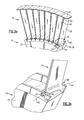
- the airfoil 26 includes three sections: an inner diameter section 30, an outer diameter section 32, and a main body portion 34 extending between the inner and outer diameter sections 30, 32.
- the airfoil 26 is comprised of a plurality of CMC fabric sheets 37, seen in detail in Figures 2b-2c .
- Each fabric sheet 37 includes a fiber mesh consisting of primary fibers 48 and secondary fibers 50.
- the fibers 48 and 50 can be Silicon-Carbide fibers, for example.
- a CMC fabric is selected such that the primary fibers 48 extend continuously and longitudinally along (or, along the length of) each fabric sheet 37.
- the primary fibers 48 extend within each CMC fabric sheet 37 such that they are generally parallel to one another.
- a plurality of the CMC fabric sheets 37 are formed, or wrapped, around a cylindrical tube 44.
- the CMC fabric sheets 37 are then layered to reach a desired thickness.
- a layered fabric sheet is generally represented at 36.
- a single and continuous layered fabric sheet 36 can be utilized to form both a pressure side 38 and a suction side 42 of the airfoil 26. That is, one portion of the layered fabric sheet 36 is used to form one side of the airfoil 26, while the other portion of the layered fabric sheet 36 is used to form the other side of the airfoil 26.
- the primary fibers 48 will generally be oriented radially outwardly from the inner diameter section 30, specifically, as the primary fibers 48 extend through the main body portion 34. It should be appreciated that by layering the CMC fabric sheets 37, the primary fibers 48 of adjacent CMC fabric sheets 37 will be generally unidirectional, and will extend generally parallel to one another.
- the main body portion 34 is formed to include a pressure side 38 and a suction side 42 typical of that known in the art. That is, the pressure side 38 and the suction side 42 are generally disposed on opposing sides of the axis 40.
- the primary fibers 48 extend generally perpendicular to the axis 40 of the tube 44. Viewed another way, the primary fibers 48 extend through the main body portion in a direction that is generally radially outward from the disk 25, shown in Figure 3a .
- the airfoil 26 When the airfoil 26 is rotated, it is subjected to stresses typical of a blade rotating through a fluid.
- the airfoil 26 is coupled to a disk 25 near the inner diameter section 30, shown in Figure 3a .
- the portions of the main body portion 34 closest to the inner diameter section 30 are subjected to a relatively large concentration of stress when compared to the rest of the main body portion 34. This is, in large part, because the portion of the airfoil 26 closest to the inner diameter section 30 is required to carry the load of the remainder of the airfoil 26.
- the airfoil 26 will be extremely strong in the direction of the fibers.
- the airfoil 26 will generally be able to withstand the stresses which airfoils are required to endure, even the relatively large stresses concentrated near the inner diameter section 30. Further, because CMC materials are extremely temperature resistant, the usage of CMC fabric sheets 37 is, again, desirable.
- the outer diameter section 32 of the airfoil 26 is shown.
- a plurality of CMC fabric sheets 37 are layered to form a layered fabric sheet 36.
- the ends 41 and 43 of the suction side 42 and the pressure side 38, respectively, of the layered fabric sheet 36 are flattened relative to one another to form an outer diameter platform capable of accommodating an outer diameter shroud 39, if required by the application.
- the outer diameter shroud, or OD shroud, 39 can comprise a plurality of layers of CMC fabric.
- the outer diameter shroud 39 serves to increase the rigidity of the respective airfoil 26 by abutting with another outer diameter shroud 39 of a like airfoil 26, shown generally in Figure 3a .
- a CMC filler material 46 is provided in voids between the pressure side 38 and the section side 42 of the layered fabric sheet 36. By providing the filler material 46, the overall rigidity of the airfoil 26 is increased.
- the inner diameter, or root, section 30 is shown.
- the CMC fabric sheets 37 may be layered around a cylindrical tube 44.
- the cylindrical tube 44 has a curved longitudinal axis 40.
- the tube 44 can be made of a metal, such as steel, for example, and can be bonded to the layered fabric sheet 36 via a resin or other known bonding agent.
- CMC filler material 46 is used to fill the void between the layered fabric sheet 36 and the tube 44.
- a turbine rotor 24 comprising a disk 25 and a plurality of airfoils 26 arranged about the outer circumference of the disk 25 is shown.
- Each airfoil 26 is coupled to the disk 25 by way of a pin 54 extending from the disk and through the tube 44.
- the pin 54 includes a curved longitudinal axis 40 similar to that of the tube 44 such that the pin 54 is capable of extending through and engaging the tube 44. Because the longitudinal axes of the tube 44 and pin 54 are curved, the contact surface area between the tube 44 and the pin 54 is increased relative to a conventional, straight axis. This increases the reliability of the connection between the tube 44 and the pin 54 and reduces the stress that is transferred from the airfoil 26 to the disk 25.
- the pin 54 can be removed from the tube 44 to facilitate replacement of a damaged or worn airfoil 26.
- the outer diameter shrouds 39 of respective airfoils 26 are arranged about the disk 25 such that they abut the adjacent airfoils 26. This restricts the movement of one airfoil 26 with respect to another, thus increasing the overall rigidity of the airfoils 26, and providing a more reliable rotor 24.
- Pin 54 extends from an opening 56 in the disk 25, through the tube 44, and into an opening formed in an opposite side of the disk 25.
- the coupling between the pin 54 and the disk 25 accommodates for the fact that the pin 54 has a curved longitudinal axis 40.
- the pin 54 may be coupled to the disk 25 using other known coupling methods.
- a flowchart depicting a method for forming the airfoil 26 using CMC fabric sheets 37 is shown.
- a tube 44 can be provided.
- a plurality of CMC fabric sheets 37 are formed, or wrapped, around the tube 44 until a desired thickness is reached.
- the CMC fabric sheets 37 are formed around the tube 44 such that the primary fibers 48 extend in a direction that is generally perpendicular to the axis 40 of the tube 44.
- a cylindrical die (with a similar axis 40) could be used in place of the tube 44. In such a case, the tube 44 would be added to the airfoil after the CMC fabric sheets 37 are layered.
- CMC filler material 46 can be provided in voids between portions of the layered fabric sheet 36, and between the layered fabric sheet 36 and the tube 44.
- the tube 44, along with the layered fabric sheet 36 and the filler material 46, can be placed into a die, heated, pressurized and allowed to cool. This is schematically represented in Figures 5d-5e .
- heat H and pressure P (seen in Figure 5e )
- the layered fabric sheet 36, the filler material 46, and the tube 44 become bonded together. It will be appreciated that the use of a bonding agent or resin may be used if needed.
- the die can cause the ends of layered fabric sheet 36 to become flattened with respect to one another, as shown generally at ends 41 and 43.
- An outer diameter shroud 39 can be added to the ends 41, 43 after the layered fabric sheet 36 has been heated and pressurized, or, alternatively, it can be inserted into the die along with the layered fabric sheet 36. Again, one of ordinary skill will appreciate that known methods, including the use of a bonding agent or resin, can be used to bond the outer diameter shroud 39 to the ends 41, 43 of the layered fabric sheet 36. CMC filler material 46 can be utilized to fill in any remaining voids in the airfoil 26.
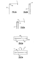
- Figures 5a-5e a method of forming the airfoil 26 is shown. While Figures 5a-5e generally correspond with the flowchart in Figure 4 , it should be appreciated that Figures 5a-5e are schematic representations and do not contradict the above description.
- FIG. 5a a schematic depicting a first CMC fabric sheet 37 as it is formed, or wrapped, around the tube 44 is provided.
- a cylindrical die may be used in place of the tube 44.
- the first CMC fabric sheet 37 from Figure 5a is shown as fully formed, or wrapped, about the tube 44.
- FIG. 5c a representation of additional CMC fabric sheets 37 being wrapped, or layered, around the first CMC fabric sheet 37 is shown. Additional CMC fabric sheets 37 can be wrapped in this manner until a desired thickness is reached. The wrapped CMC fabric sheets 37 form the layered fabric sheet 36. As depicted, the CMC fabric sheets 37 are wrapped around the tube 44 in an upside-down orientation when compared to the orientation of the airfoil 26 shown in Figure 2a . This accounts for the natural tendency of the CMC fabric sheets 37 to form around the tube 44 (by way of gravity), thus increasing the ease of the wrapping process.
- the layered fabric sheet 36 and the tube 44 are placed into a die including upper and lower die halves 60, 62.
- CMC filler material 46 can be provided in voids between respective portions of the layered fabric sheet 36, and between the layered fabric sheet 36 and the tube 44.
- filler material 46 As shown in Figures 2a-2c , formation of the airfoil 26 is assisted. That is, the die halves 60, 62 define the shape of the exterior of the airfoil 26, while the filler material 46 supports the interior of the airfoil 26.
- the die halves 60, 62 are configured to mirror the form of the airfoil 26, generally depicted in Figure 2a . Specifically, one of the die halves 60, 62 corresponds to the pressure side 38 and the other corresponds to the suction side 42 of the airfoil 26.
- the layered fabric sheet 36 and the tube 44 are treated with heat H and pressure P.
- the heat H and pressure P treatment causes the layered fabric sheet 36, the tube 44, the filler material 46 (if present), and the outer diameter shroud 39 (if present) to bond with one another.
- the layered fabric sheet 36 takes the form of the die halves 60, 62, and thus the layered fabric sheet 36 takes the general form of the airfoil 26.
- CMC materials such as Carbon, Silicon-Carbide, or Alumina based composites, etc.
- Various CMC materials are sold commercially and can be selected for use herein. Depending on operating conditions, one can select an appropriate CMC material for use in the described fabric sheets, filler material, and outer diameter shroud.
- CMC materials will allow an increase in the temperature at which the engine can be operated, and can even eliminate the need for some cooling fluids. Further, use of CMC materials in place of the metal alloys will result in significant weight saving.
Landscapes
- Engineering & Computer Science (AREA)
- Chemical & Material Sciences (AREA)
- Materials Engineering (AREA)
- Mechanical Engineering (AREA)
- General Engineering & Computer Science (AREA)
- Composite Materials (AREA)
- Turbine Rotor Nozzle Sealing (AREA)
- Structures Of Non-Positive Displacement Pumps (AREA)
- Laminated Bodies (AREA)
Abstract
Description
- This application relates to an airfoil fabricated using a ceramic matrix composite (CMC) material. The airfoil is suitable for use in a rotor of a gas turbine engine.
- Gas turbine engines typically include rotors in the turbine and compressor sections of the engine. Rotors generally include a disk and a plurality of airfoils arranged about the outer circumference of the disk. In the turbine, for example, the rotors are driven by the products of combustion. The airfoils of the turbine rotors are exposed to the products of combustion, thus they are subjected to extremely high temperatures. As the rotor is driven, the airfoils are subjected to extremely high stresses due to, for example, resistance from the fluid in the gas turbine engine. A metallic material, often a cast metal alloy such as Nickel, is typically selected for the airfoil on the basis of its capability to withstand the temperatures and stresses that airfoils are required to endure.
- In a disclosed embodiment of this invention, an airfoil is provided with an inner diameter section, an outer diameter section, and a main body portion between the inner diameter and outer diameter sections. The main body portion includes a pressure side, and a suction side opposite the pressure side. A plurality of ceramic matrix composite (CMC) fabric sheets are layered to form a layered fabric sheet. The layered fabric sheet may be formed about the inner diameter section so as to define the pressure side and the suction side of the airfoil.
- Further provided is a rotor which comprises a disk and a plurality of airfoils arranged circumferentially about the disk. The plurality of airfoils each includes an inner diameter section including a root section. The inner diameter section is coupled to the disk by way of a pin extending from the disk through a cylindrical tube in the root section. The cylindrical tube and the pin each have a curved longitudinal axis. Thus, there is a relatively large contact surface area between the tubular root section and the pin.
- Also put forth is a method for forming an airfoil utilizing a plurality of fabric sheets. Each fabric sheet includes a first and second fabric sheet portion, and a plurality of primary fibers continuously extending along the length thereof. A first fabric sheet is formed such that the first fabric sheet generally opposes the second fabric sheet portion. In this manner, the first and second fabric sheet portions each correspond to one of an airfoil pressure side and an airfoil suction side. A desired number of fabric sheets are wrapped about said first fabric sheet such that the primary fibers of the respective fabric sheets extend generally parallel to one another.
- These and other features of the present invention can be best understood from the following specification and drawings, the following of which is a brief description.
-
-
Figure 1 shows an example gas turbine engine. -
Figure 2a is a perspective view of an airfoil for a gas turbine engine. -
Figure 2b is a view of the outer diameter section of the airfoil ofFigure 2a . -
Figure 2c is a view of the inner diameter section of the airfoil ofFigure 2a . -
Figure 3a is a view of a rotor for a gas turbine engine, depicting the arrangement of the airfoils fromFigure 2a about a disk. -
Figure 3b is a view of the connection between the airfoil ofFigure 2a and the disk. -
Figure 4 is a flowchart exemplary of steps used to produce the airfoil ofFigure 2a . -
Figures 5a-5b are representative of a method for forming, or wrapping, a fabric sheet about a tube to form the airfoil ofFigure 2a . -
Figure 5c generally depicts a method for wrapping fabric sheets about the tube in order to provide the airfoil ofFigure 2a with the desired thickness. -
Figure 5d generally depicts the layered fabric sheet and tube within a die. -
Figure 5e is a schematic representation of heat and pressure being applied to the layered fabric sheet and tube. - Referring to
Figure 1 , agas turbine engine 10, such as a turbofan gas turbine engine, circumferentially disposed about an engine centerline, oraxial centerline axis 12, is shown. Theengine 10 includes ahousing 21, afan 14,compressor sections combustion section 18 and aturbine 20. As is well known in the art, air compressed in thecompressor 15/16 is mixed with fuel and burned in thecombustion section 18 and expanded inturbine 20. Theturbine 20 includesrotors 22 and 24, which rotate in response to the expansion. Theturbine 20 comprises alternating rows of rotary airfoils orblades 26 and static airfoils orvanes 28. It should be understood that this view is included simply to provide a basic understanding of the sections in a gas turbine engine, and not to limit the invention. For example, while afan 14 is shown, this invention may, be used in turbines that do not include a fan section. - Referring to
Figure 2a , arotary airfoil 26 is depicted. Theairfoil 26 includes three sections: aninner diameter section 30, anouter diameter section 32, and amain body portion 34 extending between the inner andouter diameter sections airfoil 26 is comprised of a plurality ofCMC fabric sheets 37, seen in detail inFigures 2b-2c . Eachfabric sheet 37 includes a fiber mesh consisting ofprimary fibers 48 andsecondary fibers 50. Thefibers primary fibers 48 extend continuously and longitudinally along (or, along the length of) eachfabric sheet 37. Theprimary fibers 48 extend within eachCMC fabric sheet 37 such that they are generally parallel to one another. To form theairfoil 26, explained in detail below, a plurality of theCMC fabric sheets 37 are formed, or wrapped, around acylindrical tube 44. TheCMC fabric sheets 37 are then layered to reach a desired thickness. A layered fabric sheet is generally represented at 36. In this manner, a single and continuous layeredfabric sheet 36 can be utilized to form both apressure side 38 and asuction side 42 of theairfoil 26. That is, one portion of thelayered fabric sheet 36 is used to form one side of theairfoil 26, while the other portion of thelayered fabric sheet 36 is used to form the other side of theairfoil 26. Because of the longitudinal orientation of theprimary fibers 48 with respect to eachfabric sheet 37, theprimary fibers 48 will generally be oriented radially outwardly from theinner diameter section 30, specifically, as theprimary fibers 48 extend through themain body portion 34. It should be appreciated that by layering theCMC fabric sheets 37, theprimary fibers 48 of adjacentCMC fabric sheets 37 will be generally unidirectional, and will extend generally parallel to one another. - The
main body portion 34 is formed to include apressure side 38 and asuction side 42 typical of that known in the art. That is, thepressure side 38 and thesuction side 42 are generally disposed on opposing sides of theaxis 40. Throughout the main body portion, theprimary fibers 48 extend generally perpendicular to theaxis 40 of thetube 44. Viewed another way, theprimary fibers 48 extend through the main body portion in a direction that is generally radially outward from thedisk 25, shown inFigure 3a . - When the
airfoil 26 is rotated, it is subjected to stresses typical of a blade rotating through a fluid. Theairfoil 26 is coupled to adisk 25 near theinner diameter section 30, shown inFigure 3a . The portions of themain body portion 34 closest to theinner diameter section 30 are subjected to a relatively large concentration of stress when compared to the rest of themain body portion 34. This is, in large part, because the portion of theairfoil 26 closest to theinner diameter section 30 is required to carry the load of the remainder of theairfoil 26. By providing alayered fabric sheet 36 with theprimary fibers 48 oriented in the manner described, theairfoil 26 will be extremely strong in the direction of the fibers. Thus, theairfoil 26 will generally be able to withstand the stresses which airfoils are required to endure, even the relatively large stresses concentrated near theinner diameter section 30. Further, because CMC materials are extremely temperature resistant, the usage ofCMC fabric sheets 37 is, again, desirable. - Referring to
Figure 2b , theouter diameter section 32 of theairfoil 26 is shown. As shown, and as described above, a plurality ofCMC fabric sheets 37 are layered to form alayered fabric sheet 36. In processing, the ends 41 and 43 of thesuction side 42 and thepressure side 38, respectively, of thelayered fabric sheet 36 are flattened relative to one another to form an outer diameter platform capable of accommodating anouter diameter shroud 39, if required by the application. The outer diameter shroud, or OD shroud, 39 can comprise a plurality of layers of CMC fabric. Theouter diameter shroud 39 serves to increase the rigidity of therespective airfoil 26 by abutting with anotherouter diameter shroud 39 of alike airfoil 26, shown generally inFigure 3a . ACMC filler material 46 is provided in voids between thepressure side 38 and thesection side 42 of thelayered fabric sheet 36. By providing thefiller material 46, the overall rigidity of theairfoil 26 is increased. - Referring to
Figure 2c , the inner diameter, or root,section 30 is shown. In processing, explained in detail below, theCMC fabric sheets 37 may be layered around acylindrical tube 44. Thecylindrical tube 44 has a curvedlongitudinal axis 40. Thetube 44 can be made of a metal, such as steel, for example, and can be bonded to thelayered fabric sheet 36 via a resin or other known bonding agent.CMC filler material 46 is used to fill the void between thelayered fabric sheet 36 and thetube 44. - Referring to
Figure 3a , aturbine rotor 24 comprising adisk 25 and a plurality ofairfoils 26 arranged about the outer circumference of thedisk 25 is shown. Eachairfoil 26 is coupled to thedisk 25 by way of apin 54 extending from the disk and through thetube 44. Thepin 54 includes a curvedlongitudinal axis 40 similar to that of thetube 44 such that thepin 54 is capable of extending through and engaging thetube 44. Because the longitudinal axes of thetube 44 andpin 54 are curved, the contact surface area between thetube 44 and thepin 54 is increased relative to a conventional, straight axis. This increases the reliability of the connection between thetube 44 and thepin 54 and reduces the stress that is transferred from theairfoil 26 to thedisk 25. Thepin 54 can be removed from thetube 44 to facilitate replacement of a damaged or wornairfoil 26. - As briefly explained above, the outer diameter shrouds 39 of
respective airfoils 26 are arranged about thedisk 25 such that they abut theadjacent airfoils 26. This restricts the movement of oneairfoil 26 with respect to another, thus increasing the overall rigidity of theairfoils 26, and providing a morereliable rotor 24. - Referring to
Figure 3b , a connection between theairfoil 26 and thedisk 25 is shown in detail.Pin 54 extends from anopening 56 in thedisk 25, through thetube 44, and into an opening formed in an opposite side of thedisk 25. The coupling between thepin 54 and thedisk 25 accommodates for the fact that thepin 54 has a curvedlongitudinal axis 40. Thepin 54 may be coupled to thedisk 25 using other known coupling methods. - Referring to
Figure 4 , a flowchart depicting a method for forming theairfoil 26 usingCMC fabric sheets 37 is shown. As shown, atube 44 can be provided. A plurality ofCMC fabric sheets 37 are formed, or wrapped, around thetube 44 until a desired thickness is reached. As explained above, theCMC fabric sheets 37 are formed around thetube 44 such that theprimary fibers 48 extend in a direction that is generally perpendicular to theaxis 40 of thetube 44. Alternatively, a cylindrical die (with a similar axis 40) could be used in place of thetube 44. In such a case, thetube 44 would be added to the airfoil after theCMC fabric sheets 37 are layered. Whether or not atube 44 or a cylindrical die is used, it can be said that theinner diameter portions 30 of respectiveCMC fabric sheets 37 are formed, or wrapped, about anaxis 40 to form thelayered fabric sheet 36. The process of forming, or wrapping, theCMC fabric sheets 37 is schematically represented inFigures 5a-5c . -
CMC filler material 46 can be provided in voids between portions of thelayered fabric sheet 36, and between thelayered fabric sheet 36 and thetube 44. Thetube 44, along with thelayered fabric sheet 36 and thefiller material 46, can be placed into a die, heated, pressurized and allowed to cool. This is schematically represented inFigures 5d-5e . By applying heat H and pressure P (seen inFigure 5e ), thelayered fabric sheet 36, thefiller material 46, and thetube 44 become bonded together. It will be appreciated that the use of a bonding agent or resin may be used if needed. The die can cause the ends oflayered fabric sheet 36 to become flattened with respect to one another, as shown generally at ends 41 and 43. Anouter diameter shroud 39 can be added to theends layered fabric sheet 36 has been heated and pressurized, or, alternatively, it can be inserted into the die along with thelayered fabric sheet 36. Again, one of ordinary skill will appreciate that known methods, including the use of a bonding agent or resin, can be used to bond theouter diameter shroud 39 to theends layered fabric sheet 36.CMC filler material 46 can be utilized to fill in any remaining voids in theairfoil 26. - Referring to
Figures 5a-5e , a method of forming theairfoil 26 is shown. WhileFigures 5a-5e generally correspond with the flowchart inFigure 4 , it should be appreciated thatFigures 5a-5e are schematic representations and do not contradict the above description. - Referring to
Figure 5a , a schematic depicting a firstCMC fabric sheet 37 as it is formed, or wrapped, around thetube 44 is provided. As stated above, a cylindrical die may be used in place of thetube 44. - Referring to
Figure 5b , the firstCMC fabric sheet 37 fromFigure 5a is shown as fully formed, or wrapped, about thetube 44. - Referring to
Figure 5c , a representation of additionalCMC fabric sheets 37 being wrapped, or layered, around the firstCMC fabric sheet 37 is shown. AdditionalCMC fabric sheets 37 can be wrapped in this manner until a desired thickness is reached. The wrappedCMC fabric sheets 37 form thelayered fabric sheet 36. As depicted, theCMC fabric sheets 37 are wrapped around thetube 44 in an upside-down orientation when compared to the orientation of theairfoil 26 shown inFigure 2a . This accounts for the natural tendency of theCMC fabric sheets 37 to form around the tube 44 (by way of gravity), thus increasing the ease of the wrapping process. - As seen in
Figure 5d , thelayered fabric sheet 36 and thetube 44 are placed into a die including upper and lower diehalves fabric sheet 36 and thetube 44 into the die,CMC filler material 46 can be provided in voids between respective portions of thelayered fabric sheet 36, and between thelayered fabric sheet 36 and thetube 44. By providingfiller material 46, as shown inFigures 2a-2c , formation of theairfoil 26 is assisted. That is, the die halves 60, 62 define the shape of the exterior of theairfoil 26, while thefiller material 46 supports the interior of theairfoil 26. - The die halves 60, 62 are configured to mirror the form of the
airfoil 26, generally depicted inFigure 2a . Specifically, one of the die halves 60, 62 corresponds to thepressure side 38 and the other corresponds to thesuction side 42 of theairfoil 26. - As seen in
Figure 5e , thelayered fabric sheet 36 and thetube 44 are treated with heat H and pressure P. The heat H and pressure P treatment causes thelayered fabric sheet 36, thetube 44, the filler material 46 (if present), and the outer diameter shroud 39 (if present) to bond with one another. Thelayered fabric sheet 36 takes the form of the die halves 60, 62, and thus thelayered fabric sheet 36 takes the general form of theairfoil 26. - Various CMC materials, such as Carbon, Silicon-Carbide, or Alumina based composites, etc., are sold commercially and can be selected for use herein. Depending on operating conditions, one can select an appropriate CMC material for use in the described fabric sheets, filler material, and outer diameter shroud.
- As will be appreciated, the use of CMC materials will allow an increase in the temperature at which the engine can be operated, and can even eliminate the need for some cooling fluids. Further, use of CMC materials in place of the metal alloys will result in significant weight saving.
- Although an embodiment of this invention has been disclosed, a worker of ordinary skill in this art would recognize that certain modifications would come within the scope of this invention as defined by the claims. For that reason, the following claims should be studied to determine the true scope and content of this invention.
Claims (14)
- An airfoil (26) comprising:an inner diameter section (30);an outer diameter section (32) opposite the inner diameter section;a main body portion (34) between the inner diameter and outer diameter sections;wherein a plurality of ceramic matrix composite fabric sheets (37) are layered to form a layered fabric sheet, and the layered fabric sheet is formed about the inner diameter section so as to define a pressure side and a suction side of the airfoil.
- The airfoil of claim 1 wherein each of the plurality of fabric sheets includes at least two primary fibers (48) arranged in a fiber mesh, the primary fibers continuously extending from the inner diameter section to the outer diameter section.
- The airfoil of claim 2 wherein the fabric sheets are layered such that the primary fibers of respective fabric sheets extend in substantially the same direction.
- The airfoil of claim 2 further including that the primary fibers are generally parallel to one another.
- The airfoil of claim 2, 3 or 4 further including that the primary fibers extend through the main body portion in a direction that is generally perpendicular to an axis (40) of the inner diameter section, the layered fabric sheet being formed about the axis.
- The airfoil of claim 2, 3, 4 or 5, wherein the fiber mesh includes a plurality of secondary fibers (50) oriented generally perpendicular to the primary fibers.
- The airfoil of any of claim 2 to 6, wherein the inner diameter section is capable of being coupled to a disk (25), and the primary fibers are unidirectional and will generally extend radially outwardly from the disk.
- The airfoil of any preceding claim, wherein an outer surface of the outer diameter section forms an outer diameter platform (32).
- The airfoil of claim 8 wherein the outer diameter platform is covered by an outer diameter shroud (39), the outer diameter shroud being made of a ceramic matrix composite.
- A rotor (22,24) for use in a turbine (10) or compressor (15,16) comprising:a disk (25) rotatable about an axis (12);a plurality of airfoils (26) as claimed in any preceding claim arranged circumferentially about the disk;wherein the inner diameter section (30) of each of the plurality of airfoils includes a root section; andwherein the inner diameter section is coupled to the disk by way of a pin (54) extending from the disk through a cylindrical tube (44) in the root section, each of the cylindrical tube and the pin having a curved longitudinal axis (40).
- The rotor of claim 10 wherein the plurality of airfoils each include a layered fabric sheet (37) defining the root section, a pressure side (38), and a suction side (42) thereof.
- A method of forming an airfoil (26) comprising the steps of:a) providing a plurality of fabric sheets (37), each fabric sheet including a first and second fabric sheet portion, and each fabric sheet including a plurality of primary fibers (48) continuously extending along the length thereof;b) forming a first fabric sheet such that a first fabric sheet portion of the first fabric sheet generally opposes a second fabric sheet portion of the first fabric sheet, the first and second fabric sheet portions each corresponding to one of an airfoil pressure side (38) and an airfoil suction side (42);c) wrapping a desired number of fabric sheets about said first fabric sheet such that the primary fibers of the respective fabric sheets extend generally parallel to one another.
- The method of claim 12 wherein after step (c):d) providing a filler material (46) within a void between the fabric sheets near the axis, and providing a filler material between the ends of the first and second fabric sheet portions.
- The method of claim 12 or 13 wherein after step (c):e) applying an outer diameter shroud (39) between the ends of the first and second fabric sheet portions.
Applications Claiming Priority (1)
| Application Number | Priority Date | Filing Date | Title |
|---|---|---|---|
| US12/711,297 US20110206522A1 (en) | 2010-02-24 | 2010-02-24 | Rotating airfoil fabrication utilizing cmc |
Publications (4)
| Publication Number | Publication Date |
|---|---|
| EP2363574A2 true EP2363574A2 (en) | 2011-09-07 |
| EP2363574A3 EP2363574A3 (en) | 2011-11-30 |
| EP2363574B1 EP2363574B1 (en) | 2015-09-09 |
| EP2363574B2 EP2363574B2 (en) | 2019-01-23 |
Family
ID=44170396
Family Applications (1)
| Application Number | Title | Priority Date | Filing Date |
|---|---|---|---|
| EP11250212.5A Active EP2363574B2 (en) | 2010-02-24 | 2011-02-24 | Rotating airfoil fabrication utilizing Ceramic Matrix Composites |
Country Status (2)
| Country | Link |
|---|---|
| US (1) | US20110206522A1 (en) |
| EP (1) | EP2363574B2 (en) |
Cited By (14)
| Publication number | Priority date | Publication date | Assignee | Title |
|---|---|---|---|---|
| FR2990462A1 (en) * | 2012-05-14 | 2013-11-15 | Snecma | DEVICE FOR ATTACHING AUBES TO A TURBOMACHINE ROTOR DISC |
| FR2997127A1 (en) * | 2012-10-22 | 2014-04-25 | Snecma | HIGH PRESSURE TURBINE BLADES IN CERAMIC MATRIX COMPOSITES |
| WO2014110569A1 (en) * | 2013-01-14 | 2014-07-17 | United Technologies Corporation | Organic matrix composite structural inlet guide vane for a turbine engine |
| WO2014143225A1 (en) * | 2013-03-15 | 2014-09-18 | Peter Loftus | Composite retention feature |
| EP2570611A3 (en) * | 2011-05-26 | 2015-02-11 | United Technologies Corporation | Ceramic matrix composite airfoil for a gas turbine engine and corresponding method of forming |
| WO2015041926A1 (en) * | 2013-09-17 | 2015-03-26 | United Technologies Corporation | Method for prepregging tackifier for cmc articles |
| EP2570609A3 (en) * | 2011-05-26 | 2015-07-29 | United Technologies Corporation | Ceramic matrix composite airfoil for a gas turbine engine and corresponding rotor disk assembly |
| EP2837796A4 (en) * | 2012-04-10 | 2015-12-02 | Ihi Corp | Method for manufacturing coupled turbine blades, and coupled turbine blades |
| US9308708B2 (en) | 2012-03-23 | 2016-04-12 | General Electric Company | Process for producing ceramic composite components |
| EP3026216A1 (en) * | 2014-11-20 | 2016-06-01 | Rolls-Royce North American Technologies, Inc. | Composite blades for gas turbine engines |
| US10227880B2 (en) | 2015-11-10 | 2019-03-12 | General Electric Company | Turbine blade attachment mechanism |
| US10329927B2 (en) | 2016-08-15 | 2019-06-25 | General Electric Company | Hollow ceramic matrix composite article, mandrel for forming hollow ceramic matrix composite article, and method for forming hollow ceramic matrix composite article |
| EP3587736A1 (en) * | 2018-06-22 | 2020-01-01 | United Technologies Corporation | Composite airfoil with fibres forming a cleft in the platform |
| US10556831B2 (en) | 2013-11-01 | 2020-02-11 | Mbda Uk Limited | Method of manufacturing ceramic matrix composite objects |
Families Citing this family (21)
| Publication number | Priority date | Publication date | Assignee | Title |
|---|---|---|---|---|
| US9212560B2 (en) * | 2011-06-30 | 2015-12-15 | United Technologies Corporation | CMC blade with integral 3D woven platform |
| US9103214B2 (en) * | 2011-08-23 | 2015-08-11 | United Technologies Corporation | Ceramic matrix composite vane structure with overwrap for a gas turbine engine |
| FR2995344B1 (en) * | 2012-09-10 | 2014-09-26 | Snecma | METHOD FOR MANUFACTURING AN EXHAUST CASE OF COMPOSITE MATERIAL FOR A GAS TURBINE ENGINE AND AN EXHAUST CASE THUS OBTAINED |
| US9506356B2 (en) | 2013-03-15 | 2016-11-29 | Rolls-Royce North American Technologies, Inc. | Composite retention feature |
| WO2015047485A2 (en) * | 2013-07-29 | 2015-04-02 | United Technologies Corporation | Gas turbine engine cmc airfoil assembly |
| US10273813B2 (en) * | 2015-10-29 | 2019-04-30 | General Electric Company | Ceramic matrix composite component and process of producing a ceramic matrix composite component |
| US10207471B2 (en) * | 2016-05-04 | 2019-02-19 | General Electric Company | Perforated ceramic matrix composite ply, ceramic matrix composite article, and method for forming ceramic matrix composite article |
| US10385868B2 (en) * | 2016-07-05 | 2019-08-20 | General Electric Company | Strut assembly for an aircraft engine |
| US10443410B2 (en) * | 2017-06-16 | 2019-10-15 | General Electric Company | Ceramic matrix composite (CMC) hollow blade and method of forming CMC hollow blade |
| US10941665B2 (en) | 2018-05-04 | 2021-03-09 | General Electric Company | Composite airfoil assembly for an interdigitated rotor |
| US10677075B2 (en) * | 2018-05-04 | 2020-06-09 | General Electric Company | Composite airfoil assembly for an interdigitated rotor |
| JP7150534B2 (en) * | 2018-09-13 | 2022-10-11 | 三菱重工業株式会社 | 1st stage stator vane of gas turbine and gas turbine |
| US10557361B1 (en) * | 2018-10-16 | 2020-02-11 | United Technologies Corporation | Platform for an airfoil of a gas turbine engine |
| US11919821B2 (en) | 2019-10-18 | 2024-03-05 | Rtx Corporation | Fiber reinforced composite and method of making |
| US11549380B2 (en) * | 2019-11-21 | 2023-01-10 | Raytheon Technologies Corporation | Contour weaving to form airfoil |
| US11156110B1 (en) | 2020-08-04 | 2021-10-26 | General Electric Company | Rotor assembly for a turbine section of a gas turbine engine |
| CN112267917B (en) * | 2020-09-18 | 2022-09-23 | 中国航发四川燃气涡轮研究院 | Fiber preform and ceramic matrix composite turbine outer ring |
| GB2599693B (en) * | 2020-10-09 | 2022-12-14 | Rolls Royce Plc | A heat exchanger |
| GB2599691A (en) * | 2020-10-09 | 2022-04-13 | Rolls Royce Plc | A heat exchanger |
| US11655719B2 (en) | 2021-04-16 | 2023-05-23 | General Electric Company | Airfoil assembly |
| US11781435B2 (en) | 2022-02-28 | 2023-10-10 | Rtx Corporation | Bifurcated fabric architecture for airfoils, methods of manufacture thereof and airfoils comprising the same |
Family Cites Families (35)
| Publication number | Priority date | Publication date | Assignee | Title |
|---|---|---|---|---|
| US1719415A (en) † | 1927-09-14 | 1929-07-02 | Westinghouse Electric & Mfg Co | Turbine-blade attachment |
| US2868439A (en) * | 1954-05-07 | 1959-01-13 | Goodyear Aircraft Corp | Plastic axial-flow compressor for gas turbines |
| US2929755A (en) * | 1958-07-24 | 1960-03-22 | Orenda Engines Ltd | Plastic blades for gas turbine engines |
| US3487879A (en) * | 1967-08-02 | 1970-01-06 | Dowty Rotol Ltd | Blades,suitable for propellers,compressors,fans and the like |
| US3903578A (en) * | 1972-02-28 | 1975-09-09 | United Aircraft Corp | Composite fan blade and method of construction |
| JPS5267405A (en) † | 1975-12-03 | 1977-06-03 | Mitsubishi Heavy Ind Ltd | Revoluting body |
| US4037990A (en) * | 1976-06-01 | 1977-07-26 | General Electric Company | Composite turbomachinery rotor |
| FR2497726A1 (en) * | 1981-01-12 | 1982-07-16 | Brochier Fils J | MULTILAYER TEXTILE ARTICLE FOR REINFORCING LAMINATED MATERIALS AND PROCESS FOR OBTAINING THE SAME |
| US4768924A (en) * | 1986-07-22 | 1988-09-06 | Pratt & Whitney Canada Inc. | Ceramic stator vane assembly |
| DE3826378A1 (en) * | 1988-08-03 | 1990-02-08 | Mtu Muenchen Gmbh | FIBER TECHNICAL PROPELLER BLADES |
| US5063662A (en) * | 1990-03-22 | 1991-11-12 | United Technologies Corporation | Method of forming a hollow blade |
| US5213476A (en) * | 1990-07-02 | 1993-05-25 | Hudson Products Corporation | Fan blade |
| US5129787A (en) * | 1991-02-13 | 1992-07-14 | United Technologies Corporation | Lightweight propulsor blade with internal spars and rigid base members |
| US5340280A (en) * | 1991-09-30 | 1994-08-23 | General Electric Company | Dovetail attachment for composite blade and method for making |
| US5240377A (en) * | 1992-02-25 | 1993-08-31 | Williams International Corporation | Composite fan blade |
| US6418973B1 (en) * | 1996-10-24 | 2002-07-16 | Boeing North American, Inc. | Integrally woven ceramic composites |
| US6431837B1 (en) * | 1999-06-01 | 2002-08-13 | Alexander Velicki | Stitched composite fan blade |
| US6398501B1 (en) * | 1999-09-17 | 2002-06-04 | General Electric Company | Apparatus for reducing thermal stress in turbine airfoils |
| US6451416B1 (en) * | 1999-11-19 | 2002-09-17 | United Technologies Corporation | Hybrid monolithic ceramic and ceramic matrix composite airfoil and method for making the same |
| FR2817192B1 (en) * | 2000-11-28 | 2003-08-08 | Snecma Moteurs | ASSEMBLY FORMED BY AT LEAST ONE BLADE AND A BLADE ATTACHMENT PLATFORM FOR A TURBOMACHINE, AND METHOD FOR THE PRODUCTION THEREOF |
| US6764282B2 (en) * | 2001-11-14 | 2004-07-20 | United Technologies Corporation | Blade for turbine engine |
| US6733233B2 (en) * | 2002-04-26 | 2004-05-11 | Pratt & Whitney Canada Corp. | Attachment of a ceramic shroud in a metal housing |
| US7093359B2 (en) * | 2002-09-17 | 2006-08-22 | Siemens Westinghouse Power Corporation | Composite structure formed by CMC-on-insulation process |
| US6857856B2 (en) * | 2002-09-27 | 2005-02-22 | Florida Turbine Technologies, Inc. | Tailored attachment mechanism for composite airfoils |
| WO2006059969A1 (en) * | 2004-12-01 | 2006-06-08 | United Technologies Corporation | Counter-rotating compressor case and assembly method for tip turbine engine |
| US7223465B2 (en) * | 2004-12-29 | 2007-05-29 | General Electric Company | SiC/SiC composites incorporating uncoated fibers to improve interlaminar strength |
| US7754126B2 (en) * | 2005-06-17 | 2010-07-13 | General Electric Company | Interlaminar tensile reinforcement of SiC/SiC CMC's using fugitive fibers |
| US7507466B2 (en) * | 2006-02-22 | 2009-03-24 | General Electric Company | Manufacture of CMC articles having small complex features |
| US7600978B2 (en) * | 2006-07-27 | 2009-10-13 | Siemens Energy, Inc. | Hollow CMC airfoil with internal stitch |
| US7611326B2 (en) * | 2006-09-06 | 2009-11-03 | Pratt & Whitney Canada Corp. | HP turbine vane airfoil profile |
| US20090165924A1 (en) * | 2006-11-28 | 2009-07-02 | General Electric Company | Method of manufacturing cmc articles having small complex features |
| GB2447271B (en) * | 2007-03-06 | 2010-02-17 | Rolls Royce Plc | A composite structure |
| US8042767B2 (en) * | 2007-09-04 | 2011-10-25 | The Boeing Company | Composite fabric with rigid member structure |
| US8206118B2 (en) * | 2008-01-04 | 2012-06-26 | United Technologies Corporation | Airfoil attachment |
| EP2322763A1 (en) * | 2009-11-17 | 2011-05-18 | Siemens Aktiengesellschaft | Turbine or compressor blade |
-
2010
- 2010-02-24 US US12/711,297 patent/US20110206522A1/en not_active Abandoned
-
2011
- 2011-02-24 EP EP11250212.5A patent/EP2363574B2/en active Active
Non-Patent Citations (1)
| Title |
|---|
| None |
Cited By (23)
| Publication number | Priority date | Publication date | Assignee | Title |
|---|---|---|---|---|
| EP2570611A3 (en) * | 2011-05-26 | 2015-02-11 | United Technologies Corporation | Ceramic matrix composite airfoil for a gas turbine engine and corresponding method of forming |
| EP2570609A3 (en) * | 2011-05-26 | 2015-07-29 | United Technologies Corporation | Ceramic matrix composite airfoil for a gas turbine engine and corresponding rotor disk assembly |
| US9334743B2 (en) | 2011-05-26 | 2016-05-10 | United Technologies Corporation | Ceramic matrix composite airfoil for a gas turbine engine |
| US9308708B2 (en) | 2012-03-23 | 2016-04-12 | General Electric Company | Process for producing ceramic composite components |
| EP2837796A4 (en) * | 2012-04-10 | 2015-12-02 | Ihi Corp | Method for manufacturing coupled turbine blades, and coupled turbine blades |
| US9752445B2 (en) | 2012-04-10 | 2017-09-05 | Ihi Corporation | Method for producing coupled turbine vanes, and turbine vanes |
| US9518470B2 (en) | 2012-05-14 | 2016-12-13 | Snecma | Device for attaching blades to a turbine engine rotor disk |
| FR2990462A1 (en) * | 2012-05-14 | 2013-11-15 | Snecma | DEVICE FOR ATTACHING AUBES TO A TURBOMACHINE ROTOR DISC |
| FR2997127A1 (en) * | 2012-10-22 | 2014-04-25 | Snecma | HIGH PRESSURE TURBINE BLADES IN CERAMIC MATRIX COMPOSITES |
| US9482104B2 (en) | 2012-10-22 | 2016-11-01 | Snecma | High-pressure turbine blades made of ceramic matrix composites |
| WO2014110569A1 (en) * | 2013-01-14 | 2014-07-17 | United Technologies Corporation | Organic matrix composite structural inlet guide vane for a turbine engine |
| WO2014143225A1 (en) * | 2013-03-15 | 2014-09-18 | Peter Loftus | Composite retention feature |
| US10087111B2 (en) | 2013-09-17 | 2018-10-02 | United Technologies Corporation | Method for prepregging tackifier for CMC articles |
| WO2015041926A1 (en) * | 2013-09-17 | 2015-03-26 | United Technologies Corporation | Method for prepregging tackifier for cmc articles |
| US10556831B2 (en) | 2013-11-01 | 2020-02-11 | Mbda Uk Limited | Method of manufacturing ceramic matrix composite objects |
| EP3063107B1 (en) * | 2013-11-01 | 2020-12-23 | MBDA UK Limited | Method of manufacturing ceramic matrix composite objects |
| EP3026216A1 (en) * | 2014-11-20 | 2016-06-01 | Rolls-Royce North American Technologies, Inc. | Composite blades for gas turbine engines |
| EP3239469A1 (en) * | 2014-11-20 | 2017-11-01 | Rolls-Royce North American Technologies, Inc. | Composite blades for gas turbine engines |
| US10180071B2 (en) | 2014-11-20 | 2019-01-15 | Rolls-Royce North American Technologies Inc. | Composite blades for gas turbine engines |
| US10227880B2 (en) | 2015-11-10 | 2019-03-12 | General Electric Company | Turbine blade attachment mechanism |
| US10329927B2 (en) | 2016-08-15 | 2019-06-25 | General Electric Company | Hollow ceramic matrix composite article, mandrel for forming hollow ceramic matrix composite article, and method for forming hollow ceramic matrix composite article |
| EP3284593B1 (en) * | 2016-08-15 | 2021-10-20 | General Electric Company | Hollow ceramic matrix composite article and method for forming hollow ceramic matrix composite article |
| EP3587736A1 (en) * | 2018-06-22 | 2020-01-01 | United Technologies Corporation | Composite airfoil with fibres forming a cleft in the platform |
Also Published As
| Publication number | Publication date |
|---|---|
| EP2363574B1 (en) | 2015-09-09 |
| US20110206522A1 (en) | 2011-08-25 |
| EP2363574A3 (en) | 2011-11-30 |
| EP2363574B2 (en) | 2019-01-23 |
Similar Documents
| Publication | Publication Date | Title |
|---|---|---|
| EP2363574B1 (en) | Rotating airfoil fabrication utilizing Ceramic Matrix Composites | |
| EP3064715B1 (en) | Airfoil for a gas turbine and fabrication method | |
| EP3048254B1 (en) | Vane assembly for a gas turbine engine | |
| EP3339573B1 (en) | Composite turbine vane with three-dimensional fiber reinforcements | |
| EP2562360B1 (en) | Ceramic matrix composite vane structure with overwrap for a gas turbine engine | |
| US9482108B2 (en) | Turbomachine blade assembly | |
| US8366378B2 (en) | Blade assembly | |
| EP2570611B1 (en) | Ceramic matrix composite airfoil for a gas turbine engine and corresponding method of forming | |
| EP3023581A1 (en) | Turbine disk assembly including ceramic matrix composite blades and method of manufacture | |
| CN110439626B (en) | Composite airfoil assembly for interdigitated rotors | |
| US20140271208A1 (en) | Systems and method for a composite blade with fillet transition | |
| JP2012026448A (en) | Components with bonded edges | |
| EP3865667B1 (en) | Variable stator vane and method of fabricating variable stator vane | |
| JP2017133499A (en) | Fiber reinforced airfoil | |
| EP3865663B1 (en) | Extended root region and platform over-wrap for a blade of a gas turbine engine | |
| CN110439625B (en) | Composite airfoil assembly for interdigitated rotors | |
| EP3339574B1 (en) | Turbine blade with reinforced platform for composite material construction | |
| EP3059390B1 (en) | Vane assembly for a gas turbine engine, airfoil and method of making | |
| EP3020918B1 (en) | Reinforced gas turbine engine rotor disk | |
| US11692444B2 (en) | Gas turbine engine rotor blade having a root section with composite and metallic portions | |
| US11879354B2 (en) | Rotor blade with frangible spar for a gas turbine engine | |
| US20200131092A1 (en) | Ceramic matrix composite turbine nozzle shell and method of assembly | |
| EP3287601A1 (en) | Multi-piece non-linear fan blade | |
| EP3751103B1 (en) | Ceramic matrix composite rotor blade attachment | |
| EP3951137A1 (en) | Efficient, low pressure ratio propulsor for gas turbine engines |
Legal Events
| Date | Code | Title | Description |
|---|---|---|---|
| PUAI | Public reference made under article 153(3) epc to a published international application that has entered the european phase |
Free format text: ORIGINAL CODE: 0009012 |
|
| AK | Designated contracting states |
Kind code of ref document: A2 Designated state(s): AL AT BE BG CH CY CZ DE DK EE ES FI FR GB GR HR HU IE IS IT LI LT LU LV MC MK MT NL NO PL PT RO RS SE SI SK SM TR |
|
| AX | Request for extension of the european patent |
Extension state: BA ME |
|
| PUAL | Search report despatched |
Free format text: ORIGINAL CODE: 0009013 |
|
| AK | Designated contracting states |
Kind code of ref document: A3 Designated state(s): AL AT BE BG CH CY CZ DE DK EE ES FI FR GB GR HR HU IE IS IT LI LT LU LV MC MK MT NL NO PL PT RO RS SE SI SK SM TR |
|
| AX | Request for extension of the european patent |
Extension state: BA ME |
|
| RIC1 | Information provided on ipc code assigned before grant |
Ipc: F01D 5/30 20060101ALI20111027BHEP Ipc: F01D 5/28 20060101AFI20111027BHEP |
|
| 17P | Request for examination filed |
Effective date: 20120328 |
|
| 17Q | First examination report despatched |
Effective date: 20120530 |
|
| GRAP | Despatch of communication of intention to grant a patent |
Free format text: ORIGINAL CODE: EPIDOSNIGR1 |
|
| INTG | Intention to grant announced |
Effective date: 20150602 |
|
| RIN1 | Information on inventor provided before grant (corrected) |
Inventor name: LEVASSEUR, GLENN N. Inventor name: DYE, CHRISTOPHER M. Inventor name: ALVANOS, IOANNIS Inventor name: SUCIU, GABRIEL L. |
|
| GRAS | Grant fee paid |
Free format text: ORIGINAL CODE: EPIDOSNIGR3 |
|
| GRAA | (expected) grant |
Free format text: ORIGINAL CODE: 0009210 |
|
| AK | Designated contracting states |
Kind code of ref document: B1 Designated state(s): AL AT BE BG CH CY CZ DE DK EE ES FI FR GB GR HR HU IE IS IT LI LT LU LV MC MK MT NL NO PL PT RO RS SE SI SK SM TR |
|
| REG | Reference to a national code |
Ref country code: GB Ref legal event code: FG4D |
|
| REG | Reference to a national code |
Ref country code: AT Ref legal event code: REF Ref document number: 748304 Country of ref document: AT Kind code of ref document: T Effective date: 20150915 Ref country code: CH Ref legal event code: EP |
|
| REG | Reference to a national code |
Ref country code: IE Ref legal event code: FG4D |
|
| REG | Reference to a national code |
Ref country code: DE Ref legal event code: R096 Ref document number: 602011019553 Country of ref document: DE |
|
| REG | Reference to a national code |
Ref country code: NL Ref legal event code: MP Effective date: 20150909 |
|
| PG25 | Lapsed in a contracting state [announced via postgrant information from national office to epo] |
Ref country code: NO Free format text: LAPSE BECAUSE OF FAILURE TO SUBMIT A TRANSLATION OF THE DESCRIPTION OR TO PAY THE FEE WITHIN THE PRESCRIBED TIME-LIMIT Effective date: 20151209 Ref country code: LV Free format text: LAPSE BECAUSE OF FAILURE TO SUBMIT A TRANSLATION OF THE DESCRIPTION OR TO PAY THE FEE WITHIN THE PRESCRIBED TIME-LIMIT Effective date: 20150909 Ref country code: LT Free format text: LAPSE BECAUSE OF FAILURE TO SUBMIT A TRANSLATION OF THE DESCRIPTION OR TO PAY THE FEE WITHIN THE PRESCRIBED TIME-LIMIT Effective date: 20150909 Ref country code: GR Free format text: LAPSE BECAUSE OF FAILURE TO SUBMIT A TRANSLATION OF THE DESCRIPTION OR TO PAY THE FEE WITHIN THE PRESCRIBED TIME-LIMIT Effective date: 20151210 Ref country code: FI Free format text: LAPSE BECAUSE OF FAILURE TO SUBMIT A TRANSLATION OF THE DESCRIPTION OR TO PAY THE FEE WITHIN THE PRESCRIBED TIME-LIMIT Effective date: 20150909 |
|
| REG | Reference to a national code |
Ref country code: LT Ref legal event code: MG4D |
|
| REG | Reference to a national code |
Ref country code: AT Ref legal event code: MK05 Ref document number: 748304 Country of ref document: AT Kind code of ref document: T Effective date: 20150909 |
|
| PG25 | Lapsed in a contracting state [announced via postgrant information from national office to epo] |
Ref country code: SE Free format text: LAPSE BECAUSE OF FAILURE TO SUBMIT A TRANSLATION OF THE DESCRIPTION OR TO PAY THE FEE WITHIN THE PRESCRIBED TIME-LIMIT Effective date: 20150909 Ref country code: RS Free format text: LAPSE BECAUSE OF FAILURE TO SUBMIT A TRANSLATION OF THE DESCRIPTION OR TO PAY THE FEE WITHIN THE PRESCRIBED TIME-LIMIT Effective date: 20150909 Ref country code: ES Free format text: LAPSE BECAUSE OF FAILURE TO SUBMIT A TRANSLATION OF THE DESCRIPTION OR TO PAY THE FEE WITHIN THE PRESCRIBED TIME-LIMIT Effective date: 20150909 Ref country code: HR Free format text: LAPSE BECAUSE OF FAILURE TO SUBMIT A TRANSLATION OF THE DESCRIPTION OR TO PAY THE FEE WITHIN THE PRESCRIBED TIME-LIMIT Effective date: 20150909 |
|
| PG25 | Lapsed in a contracting state [announced via postgrant information from national office to epo] |
Ref country code: NL Free format text: LAPSE BECAUSE OF FAILURE TO SUBMIT A TRANSLATION OF THE DESCRIPTION OR TO PAY THE FEE WITHIN THE PRESCRIBED TIME-LIMIT Effective date: 20150909 |
|
| PG25 | Lapsed in a contracting state [announced via postgrant information from national office to epo] |
Ref country code: CZ Free format text: LAPSE BECAUSE OF FAILURE TO SUBMIT A TRANSLATION OF THE DESCRIPTION OR TO PAY THE FEE WITHIN THE PRESCRIBED TIME-LIMIT Effective date: 20150909 Ref country code: IT Free format text: LAPSE BECAUSE OF FAILURE TO SUBMIT A TRANSLATION OF THE DESCRIPTION OR TO PAY THE FEE WITHIN THE PRESCRIBED TIME-LIMIT Effective date: 20150909 Ref country code: EE Free format text: LAPSE BECAUSE OF FAILURE TO SUBMIT A TRANSLATION OF THE DESCRIPTION OR TO PAY THE FEE WITHIN THE PRESCRIBED TIME-LIMIT Effective date: 20150909 Ref country code: IS Free format text: LAPSE BECAUSE OF FAILURE TO SUBMIT A TRANSLATION OF THE DESCRIPTION OR TO PAY THE FEE WITHIN THE PRESCRIBED TIME-LIMIT Effective date: 20160109 Ref country code: SK Free format text: LAPSE BECAUSE OF FAILURE TO SUBMIT A TRANSLATION OF THE DESCRIPTION OR TO PAY THE FEE WITHIN THE PRESCRIBED TIME-LIMIT Effective date: 20150909 |
|
| PG25 | Lapsed in a contracting state [announced via postgrant information from national office to epo] |
Ref country code: RO Free format text: LAPSE BECAUSE OF FAILURE TO SUBMIT A TRANSLATION OF THE DESCRIPTION OR TO PAY THE FEE WITHIN THE PRESCRIBED TIME-LIMIT Effective date: 20150909 Ref country code: BE Free format text: LAPSE BECAUSE OF NON-PAYMENT OF DUE FEES Effective date: 20160229 Ref country code: AT Free format text: LAPSE BECAUSE OF FAILURE TO SUBMIT A TRANSLATION OF THE DESCRIPTION OR TO PAY THE FEE WITHIN THE PRESCRIBED TIME-LIMIT Effective date: 20150909 Ref country code: PL Free format text: LAPSE BECAUSE OF FAILURE TO SUBMIT A TRANSLATION OF THE DESCRIPTION OR TO PAY THE FEE WITHIN THE PRESCRIBED TIME-LIMIT Effective date: 20150909 Ref country code: PT Free format text: LAPSE BECAUSE OF FAILURE TO SUBMIT A TRANSLATION OF THE DESCRIPTION OR TO PAY THE FEE WITHIN THE PRESCRIBED TIME-LIMIT Effective date: 20160111 |
|
| REG | Reference to a national code |
Ref country code: DE Ref legal event code: R026 Ref document number: 602011019553 Country of ref document: DE |
|
| PLBI | Opposition filed |
Free format text: ORIGINAL CODE: 0009260 |
|
| 26 | Opposition filed |
Opponent name: SNECMA Effective date: 20160603 |
|
| PLAX | Notice of opposition and request to file observation + time limit sent |
Free format text: ORIGINAL CODE: EPIDOSNOBS2 |
|
| PG25 | Lapsed in a contracting state [announced via postgrant information from national office to epo] |
Ref country code: SI Free format text: LAPSE BECAUSE OF FAILURE TO SUBMIT A TRANSLATION OF THE DESCRIPTION OR TO PAY THE FEE WITHIN THE PRESCRIBED TIME-LIMIT Effective date: 20150909 Ref country code: DK Free format text: LAPSE BECAUSE OF FAILURE TO SUBMIT A TRANSLATION OF THE DESCRIPTION OR TO PAY THE FEE WITHIN THE PRESCRIBED TIME-LIMIT Effective date: 20150909 |
|
| REG | Reference to a national code |
Ref country code: FR Ref legal event code: PLFP Year of fee payment: 6 |
|
| PG25 | Lapsed in a contracting state [announced via postgrant information from national office to epo] |
Ref country code: LU Free format text: LAPSE BECAUSE OF FAILURE TO SUBMIT A TRANSLATION OF THE DESCRIPTION OR TO PAY THE FEE WITHIN THE PRESCRIBED TIME-LIMIT Effective date: 20160224 Ref country code: MC Free format text: LAPSE BECAUSE OF FAILURE TO SUBMIT A TRANSLATION OF THE DESCRIPTION OR TO PAY THE FEE WITHIN THE PRESCRIBED TIME-LIMIT Effective date: 20150909 |
|
| PLAB | Opposition data, opponent's data or that of the opponent's representative modified |
Free format text: ORIGINAL CODE: 0009299OPPO |
|
| REG | Reference to a national code |
Ref country code: CH Ref legal event code: PL |
|
| RAP2 | Party data changed (patent owner data changed or rights of a patent transferred) |
Owner name: UNITED TECHNOLOGIES CORPORATION |
|
| PG25 | Lapsed in a contracting state [announced via postgrant information from national office to epo] |
Ref country code: CH Free format text: LAPSE BECAUSE OF NON-PAYMENT OF DUE FEES Effective date: 20160229 Ref country code: LI Free format text: LAPSE BECAUSE OF NON-PAYMENT OF DUE FEES Effective date: 20160229 |
|
| R26 | Opposition filed (corrected) |
Opponent name: SAFRAN AIRCRAFT ENGINES Effective date: 20160603 |
|
| PLBB | Reply of patent proprietor to notice(s) of opposition received |
Free format text: ORIGINAL CODE: EPIDOSNOBS3 |
|
| REG | Reference to a national code |
Ref country code: IE Ref legal event code: MM4A |
|
| PG25 | Lapsed in a contracting state [announced via postgrant information from national office to epo] |
Ref country code: BE Free format text: LAPSE BECAUSE OF FAILURE TO SUBMIT A TRANSLATION OF THE DESCRIPTION OR TO PAY THE FEE WITHIN THE PRESCRIBED TIME-LIMIT Effective date: 20150909 |
|
| REG | Reference to a national code |
Ref country code: FR Ref legal event code: PLFP Year of fee payment: 7 |
|
| PG25 | Lapsed in a contracting state [announced via postgrant information from national office to epo] |
Ref country code: IE Free format text: LAPSE BECAUSE OF NON-PAYMENT OF DUE FEES Effective date: 20160224 |
|
| REG | Reference to a national code |
Ref country code: DE Ref legal event code: R082 Ref document number: 602011019553 Country of ref document: DE Representative=s name: SCHMITT-NILSON SCHRAUD WAIBEL WOHLFROM PATENTA, DE |
|
| REG | Reference to a national code |
Ref country code: DE Ref legal event code: R082 Ref document number: 602011019553 Country of ref document: DE Representative=s name: SCHMITT-NILSON SCHRAUD WAIBEL WOHLFROM PATENTA, DE Ref country code: DE Ref legal event code: R081 Ref document number: 602011019553 Country of ref document: DE Owner name: UNITED TECHNOLOGIES CORP. (N.D.GES.D. STAATES , US Free format text: FORMER OWNER: UNITED TECHNOLOGIES CORPORATION, HARTFORD, CONN., US |
|
| PG25 | Lapsed in a contracting state [announced via postgrant information from national office to epo] |
Ref country code: MT Free format text: LAPSE BECAUSE OF FAILURE TO SUBMIT A TRANSLATION OF THE DESCRIPTION OR TO PAY THE FEE WITHIN THE PRESCRIBED TIME-LIMIT Effective date: 20150909 |
|
| REG | Reference to a national code |
Ref country code: FR Ref legal event code: PLFP Year of fee payment: 8 |
|
| PG25 | Lapsed in a contracting state [announced via postgrant information from national office to epo] |
Ref country code: HU Free format text: LAPSE BECAUSE OF FAILURE TO SUBMIT A TRANSLATION OF THE DESCRIPTION OR TO PAY THE FEE WITHIN THE PRESCRIBED TIME-LIMIT; INVALID AB INITIO Effective date: 20110224 Ref country code: SM Free format text: LAPSE BECAUSE OF FAILURE TO SUBMIT A TRANSLATION OF THE DESCRIPTION OR TO PAY THE FEE WITHIN THE PRESCRIBED TIME-LIMIT Effective date: 20150909 Ref country code: CY Free format text: LAPSE BECAUSE OF FAILURE TO SUBMIT A TRANSLATION OF THE DESCRIPTION OR TO PAY THE FEE WITHIN THE PRESCRIBED TIME-LIMIT Effective date: 20150909 |
|
| PG25 | Lapsed in a contracting state [announced via postgrant information from national office to epo] |
Ref country code: TR Free format text: LAPSE BECAUSE OF FAILURE TO SUBMIT A TRANSLATION OF THE DESCRIPTION OR TO PAY THE FEE WITHIN THE PRESCRIBED TIME-LIMIT Effective date: 20150909 Ref country code: MK Free format text: LAPSE BECAUSE OF FAILURE TO SUBMIT A TRANSLATION OF THE DESCRIPTION OR TO PAY THE FEE WITHIN THE PRESCRIBED TIME-LIMIT Effective date: 20150909 Ref country code: MT Free format text: LAPSE BECAUSE OF FAILURE TO SUBMIT A TRANSLATION OF THE DESCRIPTION OR TO PAY THE FEE WITHIN THE PRESCRIBED TIME-LIMIT Effective date: 20160229 |
|
| PG25 | Lapsed in a contracting state [announced via postgrant information from national office to epo] |
Ref country code: BG Free format text: LAPSE BECAUSE OF FAILURE TO SUBMIT A TRANSLATION OF THE DESCRIPTION OR TO PAY THE FEE WITHIN THE PRESCRIBED TIME-LIMIT Effective date: 20150909 |
|
| PG25 | Lapsed in a contracting state [announced via postgrant information from national office to epo] |
Ref country code: AL Free format text: LAPSE BECAUSE OF FAILURE TO SUBMIT A TRANSLATION OF THE DESCRIPTION OR TO PAY THE FEE WITHIN THE PRESCRIBED TIME-LIMIT Effective date: 20150909 |
|
| PUAH | Patent maintained in amended form |
Free format text: ORIGINAL CODE: 0009272 |
|
| STAA | Information on the status of an ep patent application or granted ep patent |
Free format text: STATUS: PATENT MAINTAINED AS AMENDED |
|
| 27A | Patent maintained in amended form |
Effective date: 20190123 |
|
| AK | Designated contracting states |
Kind code of ref document: B2 Designated state(s): AL AT BE BG CH CY CZ DE DK EE ES FI FR GB GR HR HU IE IS IT LI LT LU LV MC MK MT NL NO PL PT RO RS SE SI SK SM TR |
|
| REG | Reference to a national code |
Ref country code: DE Ref legal event code: R102 Ref document number: 602011019553 Country of ref document: DE |
|
| REG | Reference to a national code |
Ref country code: DE Ref legal event code: R081 Ref document number: 602011019553 Country of ref document: DE Owner name: RAYTHEON TECHNOLOGIES CORPORATION (N.D.GES.D.S, US Free format text: FORMER OWNER: UNITED TECHNOLOGIES CORP. (N.D.GES.D. STAATES DELAWARE), FARMINGTON, CONN., US |
|
| P01 | Opt-out of the competence of the unified patent court (upc) registered |
Effective date: 20230520 |
|
| PGFP | Annual fee paid to national office [announced via postgrant information from national office to epo] |
Ref country code: DE Payment date: 20240123 Year of fee payment: 14 Ref country code: GB Payment date: 20240123 Year of fee payment: 14 |
|
| PGFP | Annual fee paid to national office [announced via postgrant information from national office to epo] |
Ref country code: FR Payment date: 20240123 Year of fee payment: 14 |