EP2363306A2 - System und Verfahren für automatisierte Anhängerkupplung - Google Patents
System und Verfahren für automatisierte Anhängerkupplung Download PDFInfo
- Publication number
- EP2363306A2 EP2363306A2 EP11156693A EP11156693A EP2363306A2 EP 2363306 A2 EP2363306 A2 EP 2363306A2 EP 11156693 A EP11156693 A EP 11156693A EP 11156693 A EP11156693 A EP 11156693A EP 2363306 A2 EP2363306 A2 EP 2363306A2
- Authority
- EP
- European Patent Office
- Prior art keywords
- vehicle
- towing
- hook
- unit
- connection means
- Prior art date
- Legal status (The legal status is an assumption and is not a legal conclusion. Google has not performed a legal analysis and makes no representation as to the accuracy of the status listed.)
- Granted
Links
Images


Classifications
-
- B—PERFORMING OPERATIONS; TRANSPORTING
- B60—VEHICLES IN GENERAL
- B60D—VEHICLE CONNECTIONS
- B60D1/00—Traction couplings; Hitches; Draw-gear; Towing devices
- B60D1/14—Draw-gear or towing devices characterised by their type
- B60D1/18—Tow ropes, chains or the like
-
- B—PERFORMING OPERATIONS; TRANSPORTING
- B60—VEHICLES IN GENERAL
- B60D—VEHICLE CONNECTIONS
- B60D1/00—Traction couplings; Hitches; Draw-gear; Towing devices
- B60D1/01—Traction couplings or hitches characterised by their type
- B60D1/04—Hook or hook-and-hasp couplings
-
- B—PERFORMING OPERATIONS; TRANSPORTING
- B60—VEHICLES IN GENERAL
- B60D—VEHICLE CONNECTIONS
- B60D1/00—Traction couplings; Hitches; Draw-gear; Towing devices
- B60D1/24—Traction couplings; Hitches; Draw-gear; Towing devices characterised by arrangements for particular functions
- B60D1/36—Traction couplings; Hitches; Draw-gear; Towing devices characterised by arrangements for particular functions for facilitating connection, e.g. hitch catchers
Definitions
- FIGs. 1A and 1B are schematic illustrations of a towing unit and towed unit of an automated tow coupling system according to some embodiments of the present invention
- Figs. 2A, 2B and 2C are schematic side-view illustrations of an automated tow coupling system according to some embodiments of the present invention.
- Fig. 3 is a schematic top view illustration of an automated tow coupling system according to some embodiments of the present invention.
- Figs. 4A and 4B are schematic partial top view illustrations of an automated tow coupling system according to some embodiments of the present invention.
- Fig. 5 is a schematic top view illustration of an automated tow coupling system according to some embodiments of the present invention.
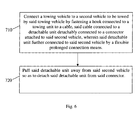
- Fig. 6 is a flow chart illustrating a method for automated tow coupling according to some embodiments of the present invention..
- Embodiments of the present invention may provide a tow coupling system, which facilitates quick automated fastening of a towing unit to a towed unit by a hook connected to the towing unit and a cable connected to the towed unit by a detachable unit.
- a tow coupling system which facilitates quick automated fastening of a towing unit to a towed unit by a hook connected to the towing unit and a cable connected to the towed unit by a detachable unit.
- the detachable unit detaches from an adapter connected to the towed vehicle, and remains connected to the vehicle by chains. Therefore, the pulling forces during towing are operated on the cable and chains only. Therefore, the tow coupling system according to the present invention may be relatively light and cheap and does not require massive connectors durable under the pulling forces.
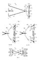
- FIGs. 1A and 1B are schematic illustrations of a towing unit 100 and towed unit 200 of an automated tow coupling system 10 (a view of the whole system 10 is shown in Figs. 2A-2C, 3 and 5 ) according to some embodiments of the present invention.
- Towing unit 100 may be connected to a rear portion of a towing vehicle 500, and towed unit 200 may be connected to a front portion of a vehicle 600 to be towed, for example, by vehicle 500.
- towed unit 200 may be used for towing non-vehicle units, such as a big container, or the like.
- Towing unit 100 may include a permanent connector 110 and rings 112, which may be permanently or otherwise connected to a towing portion, such as a rear portion, of a towing vehicle 500. Additionally, towing unit 100 may include a mounted towing unit 120 which may be mounted on permanent connector 110. Mounted towing unit 120 may include an adapter 122, an arm 124, a hook 126, an elevation guide 125 and a chain 123. Adapter 122 may be installed on permanent connector 110 so as to enable connection of mounted towing unit 120 to permanent connector 110. Arm 124 may be pivotally connected to adapter 122.
- Hook 126 may be detachably connected to a distal end of arm 124, for example such as to enable detaching of hook 126 from arm 124 when a pulling force is operated on hook 126, for example when hook 126 is fastened to towed unit 200 and/or when towing vehicle 500 moves away from vehicle 600 and thus, for example, detaches and draws arm 124 away from hook 126.
- a mechanism may cause detachment of hook 126 from arm 124 upon fastening of hook 126 to towed unit 200 and thus pulling hook 126 away from arm 124.
- Chain 123 may also be, in some embodiments, a cable or a rope or any other suitable strong and flexible prolonged connection means, adapted to provide the required towing force.
- Chain 123 may be connected to rings 112. Additionally, chain 123 may be connected to hook 126 so that, for example, hook 126 may remain connected to rings 112 by chain 123 when hook 126 is detached from arm 124. Elevation guide 125 may facilitate connection of hook 126 to towed unit 200, as described in more detail herein below.
- Towed unit 200 may include a permanent connector 210 and rings 212, which may be permanently or otherwise connected to a towed portion, such as front portion of towed vehicle 600. Additionally, towed unit 200 may include a mounted towed unit 220, which may be mounted on permanent connector 210. Mounted towed unit 220 may include an adapter 222, one or more detachable units 224, a cable 226 and chains 223. Adapter 222 may be installed on permanent connector 210 so as to enable connection of mounted towed unit 220 to permanent connector 210. Detachable unit 224 may be detachably connected to adapter 222 by any suitable detachable connectors, for example, snapping connectors.
- detachable unit 224 may be detachably connected to adapter 222 by pins 225 which may snap into, or out of slots 227 (which are shown more clearly in Figs. 4A and 4B ).
- Two distal ends of cable 226 may be attached to detachable units 224.
- Cable 226 may have a desired amount of stiffness which ensures that it substantially maintains its shape and position with respect to detachable units 224 and does not, for example, collapse downwardly before engagement with hook 126 occurs, for example due to its self weight. When the rear portion of vehicle 500 advances towards the front portion of vehicle 600, hook 126 becomes in contact with cable 226.
- Cable 226 may be stable enough and/or may be held firmly by detachable unit 224, so as to prevent excessive movement of the cable and thus, for example, enabling automated connection to hook 126 as described below.
- elevation guide 125 causes hook 126 to rise above cable 226.
- tip 128 of hook 126 may pass cable 226.
- hook 126 may slide down on cable 226 and become fastened to cable 226, thus completing an automated connection process. After hook 126 is fastened to cable, vehicle 500 may move away from vehicle 600.
- hook 126 may pull cable 226 and thus, for example, detachable units 224 may be detached from adapter 222.
- pins 225 may be snapped out from slots 227.
- Chains 223 may be connected at one distal end to rings 212 and at other distal end to detachable units 224 so that, for example, detachable units 224 may remain connected to rings 212 by chains 223 when detachable units 224 are detached from adapter 222.
- FIGs. 2A, 2B and 2C are schematic side-view illustrations of automated tow coupling system 10 according to some embodiments of the present invention.
- Figs. 2A, 2B and 2C show the process of coupling of hook 126 to cable 226.
- the same referral numbers refer to the same elements of system 10 as in Figs. 1A and 1B .
- Elevation guide 125 facilitates and/or guides hook 126 upwards and above 226 when vehicle 500 continues advancing towards vehicle 600, thus compensating for a large height differences between vehicle 500 and vehicle 600.
- edge 128 passes cable 226, hook 126 descends on cable 226 and becomes fastened to cable 226, as shown in Fig. 2B .
- hook 126 may detach from arm 124, as shown in Fig. 2C .
- a mechanism may cause detachment of hook 126 from arm 124 upon fastening of hook 126 to cable 226.
- hook 126 detaches from arm 124, hook 126 remains connected to rings 112 by chain 123, as shown in Fig. 2C .
- Fig. 3 is a schematic top view illustration of automated tow coupling system 10 according to some embodiments of the present invention.
- the same referral numbers refer to the same elements of system 10 as in the previous figures.
- hook 126 detaches from arm 124, hook 126 remains connected to rings 112 by chain 123.
- chain 123 stretches as shown in Fig. 3 .
- hook 126 starts pulling cable 226.
- Figs. 4A and 4B are schematic partial top view illustrations of automated tow coupling system 10 according to some embodiments of the present invention.
- the same referral numbers refer to the same elements of system 10 as in the previous figures.
- Figs. 4A and 4B show different stages of detachment of detachable units 224 from adapter 222.
- hook 126 pulls cable 226 with a pulling force higher than a certain amount
- detachable units 224 detach from adapter 222.
- detachable units 224 are detachably connected to adapter 222 by any suitable detachable connectors, for example, snapping connectors.
- detachable units 224 are detachably connected to adapter 222 by pins 225 which may respectively snap into slots 227.
- pins 225 which may respectively snap into slots 227.
- detachable units 224 may detach from adapter 222 by snapping pins 225 out of slots 227.
- detachable units 224 detaches from adapter 222, it remains connected to rings 212 by chains 223.
- FIG. 5 is a schematic top view illustration of automated tow coupling system 10 according to some embodiments of the present invention.
- the same referral numbers refer to the same elements of system 10 as in the previous figures.
- Fig. 5 shows the configuration of tow coupling system 10 after detachable units 224 detach from adapter 222 and remain attached to rings 212 by chains 223.
- chains 223 stretch.
- dragging of vehicle 600 by vehicle 500 is initiated, wherein the connection between vehicle 500 and vehicle 600 is by chains 123 and 223 connected at rings 112 and 212, respectively.
- automated tow coupling system 10 may facilitate automated connection of a towing vehicle to a towed one without needing human assistance or intervention, thus allowing, for example, soldiers in a battle field who are under threat or fire to remain protected inside their armored vehicles while a towing armored vehicle is connecting and then towing a faulty armored vehicle, away from the scene.
- Automated tow coupling system 10 allows taking advantage of existing towing points, such as rings 112, 212, adapted to stand high towing forces, which are typically provided with an armored vehicle and provide an automated connecting system which is relatively light-weight and simple thus ensuring high yield and low at-field
- the method may include connecting a towing vehicle to a second vehicle to be towed by said towing vehicle by fastening a hook connected to a towing unit to a cable, said cable connected to a detachable unit detachably connected to a connector attached to said second vehicle, wherein said detachable unit further connected to said second vehicle by a flexible prolonged connection means.
- the method may include pulling said detachable unit away from said second vehicle so as to detach said detachable unit from said connector.
Landscapes
- Engineering & Computer Science (AREA)
- Transportation (AREA)
- Mechanical Engineering (AREA)
- Platform Screen Doors And Railroad Systems (AREA)
- Handcart (AREA)
Applications Claiming Priority (1)
| Application Number | Priority Date | Filing Date | Title |
|---|---|---|---|
| US30965610P | 2010-03-02 | 2010-03-02 |
Publications (3)
| Publication Number | Publication Date |
|---|---|
| EP2363306A2 true EP2363306A2 (de) | 2011-09-07 |
| EP2363306A3 EP2363306A3 (de) | 2013-06-19 |
| EP2363306B1 EP2363306B1 (de) | 2016-01-13 |
Family
ID=44169560
Family Applications (1)
| Application Number | Title | Priority Date | Filing Date |
|---|---|---|---|
| EP11156693.1A Not-in-force EP2363306B1 (de) | 2010-03-02 | 2011-03-02 | System und Verfahren für automatisierte Anhängerkupplung |
Country Status (1)
| Country | Link |
|---|---|
| EP (1) | EP2363306B1 (de) |
Family Cites Families (2)
| Publication number | Priority date | Publication date | Assignee | Title |
|---|---|---|---|---|
| US5261687A (en) * | 1992-01-06 | 1993-11-16 | Bergman Manufacturing, Inc. | Automatic hitch assembly |
| IL188467A (en) * | 2006-12-28 | 2012-08-30 | Eliahu Tayar | Device, system and method for automated tow coupling |
-
2011
- 2011-03-02 EP EP11156693.1A patent/EP2363306B1/de not_active Not-in-force
Non-Patent Citations (1)
| Title |
|---|
| None |
Also Published As
| Publication number | Publication date |
|---|---|
| EP2363306B1 (de) | 2016-01-13 |
| EP2363306A3 (de) | 2013-06-19 |
Similar Documents
| Publication | Publication Date | Title |
|---|---|---|
| WO2008114830A1 (ja) | 光コネクタ付光ファイバケーブル及び該光ファイバケーブルの通線方法、該通線方法に用いる牽引部品及び光コネクタ | |
| EP3617761A3 (de) | Klammer für faseroptischen verbinder | |
| EP2671803A3 (de) | System und Verfahren zum Verbinden zweier Raumschiffe als Ladung | |
| EP2400108A3 (de) | Vorrichtung und Verfahren zum fluidischen Koppeln von rohrförmigen Abschnitten und rohrförmiges System daraus | |
| CN109835500B (zh) | 用于尾向安装拆卸发动机的系统的飞机和尾向拆卸发动机的方法 | |
| EP2781964A3 (de) | Kombinierte Einheiten und Bilderzeugungssystem | |
| CN118952118B (zh) | 用于术中超声探头的拆卸工装 | |
| EP2363306B1 (de) | System und Verfahren für automatisierte Anhängerkupplung | |
| EP2293004A3 (de) | Kopplungsbaugruppe für eine Farhzeug-Klimaanlage | |
| US10723594B2 (en) | Coupling unit | |
| EP2306596A3 (de) | Bandverbindungsvorrichtung für elektrische Leitfähigkeit | |
| EP2590284A3 (de) | Montagevorrichtung zum Halten und Führen eines Kabels an einen Strukturbauteil eines Luft- oder Raumfahrzeugs, und ein Luft- oder Raumfahrzeug | |
| RU2018114498A (ru) | Система и способ испытания лобового смещенного удара | |
| CN104552379B (zh) | 一种加工汽车驻车拉索用的剥皮切断装置 | |
| EP2366565A3 (de) | Kontaktvorrichtungsanordnung für eine Anhängekupplung | |
| EP2689664A3 (de) | Verfahren und Anlage zur zeitlich begrenzten Aufnahme von Backgutträgern | |
| KR20090106525A (ko) | 연결이 풀려진 후에 케이블 손상을 방지하는 케이블 리트랙터를 위한 방법들 및 장치 | |
| CN107092057B (zh) | 一种光纤活动连接器安装结构 | |
| CN208582377U (zh) | 内窥镜手柄控制端与牵引钢丝的连接结构 | |
| CN118457919A (zh) | 一种无人机救援索道搭建装置 | |
| CN102951092B (zh) | 用于交通工具的框架的核心 | |
| CN212529212U (zh) | 一种汽车前拖车钩 | |
| CN213304948U (zh) | 一种线缆收纳装置 | |
| CN101898591A (zh) | 一种扩展方舱 | |
| CN215219963U (zh) | 一种多功能飞机牵引模拟训练装置 |
Legal Events
| Date | Code | Title | Description |
|---|---|---|---|
| PUAI | Public reference made under article 153(3) epc to a published international application that has entered the european phase |
Free format text: ORIGINAL CODE: 0009012 |
|
| AK | Designated contracting states |
Kind code of ref document: A2 Designated state(s): AL AT BE BG CH CY CZ DE DK EE ES FI FR GB GR HR HU IE IS IT LI LT LU LV MC MK MT NL NO PL PT RO RS SE SI SK SM TR |
|
| AX | Request for extension of the european patent |
Extension state: BA ME |
|
| PUAL | Search report despatched |
Free format text: ORIGINAL CODE: 0009013 |
|
| AK | Designated contracting states |
Kind code of ref document: A3 Designated state(s): AL AT BE BG CH CY CZ DE DK EE ES FI FR GB GR HR HU IE IS IT LI LT LU LV MC MK MT NL NO PL PT RO RS SE SI SK SM TR |
|
| AX | Request for extension of the european patent |
Extension state: BA ME |
|
| RIC1 | Information provided on ipc code assigned before grant |
Ipc: B60D 1/36 20060101ALI20130514BHEP Ipc: B60D 1/18 20060101ALI20130514BHEP Ipc: B60D 1/04 20060101AFI20130514BHEP |
|
| 17P | Request for examination filed |
Effective date: 20131218 |
|
| RBV | Designated contracting states (corrected) |
Designated state(s): AL AT BE BG CH CY CZ DE DK EE ES FI FR GB GR HR HU IE IS IT LI LT LU LV MC MK MT NL NO PL PT RO RS SE SI SK SM TR |
|
| GRAP | Despatch of communication of intention to grant a patent |
Free format text: ORIGINAL CODE: EPIDOSNIGR1 |
|
| INTG | Intention to grant announced |
Effective date: 20150611 |
|
| GRAP | Despatch of communication of intention to grant a patent |
Free format text: ORIGINAL CODE: EPIDOSNIGR1 |
|
| GRAS | Grant fee paid |
Free format text: ORIGINAL CODE: EPIDOSNIGR3 |
|
| INTG | Intention to grant announced |
Effective date: 20151102 |
|
| GRAA | (expected) grant |
Free format text: ORIGINAL CODE: 0009210 |
|
| AK | Designated contracting states |
Kind code of ref document: B1 Designated state(s): AL AT BE BG CH CY CZ DE DK EE ES FI FR GB GR HR HU IE IS IT LI LT LU LV MC MK MT NL NO PL PT RO RS SE SI SK SM TR |
|
| REG | Reference to a national code |
Ref country code: GB Ref legal event code: FG4D |
|
| REG | Reference to a national code |
Ref country code: CH Ref legal event code: EP |
|
| REG | Reference to a national code |
Ref country code: IE Ref legal event code: FG4D |
|
| REG | Reference to a national code |
Ref country code: AT Ref legal event code: REF Ref document number: 770251 Country of ref document: AT Kind code of ref document: T Effective date: 20160215 |
|
| REG | Reference to a national code |
Ref country code: FR Ref legal event code: PLFP Year of fee payment: 6 |
|
| REG | Reference to a national code |
Ref country code: DE Ref legal event code: R096 Ref document number: 602011022565 Country of ref document: DE |
|
| REG | Reference to a national code |
Ref country code: LT Ref legal event code: MG4D |
|
| REG | Reference to a national code |
Ref country code: NL Ref legal event code: MP Effective date: 20160113 |
|
| REG | Reference to a national code |
Ref country code: AT Ref legal event code: MK05 Ref document number: 770251 Country of ref document: AT Kind code of ref document: T Effective date: 20160113 |
|
| PG25 | Lapsed in a contracting state [announced via postgrant information from national office to epo] |
Ref country code: NL Free format text: LAPSE BECAUSE OF FAILURE TO SUBMIT A TRANSLATION OF THE DESCRIPTION OR TO PAY THE FEE WITHIN THE PRESCRIBED TIME-LIMIT Effective date: 20160113 |
|
| PG25 | Lapsed in a contracting state [announced via postgrant information from national office to epo] |
Ref country code: IT Free format text: LAPSE BECAUSE OF FAILURE TO SUBMIT A TRANSLATION OF THE DESCRIPTION OR TO PAY THE FEE WITHIN THE PRESCRIBED TIME-LIMIT Effective date: 20160113 Ref country code: HR Free format text: LAPSE BECAUSE OF FAILURE TO SUBMIT A TRANSLATION OF THE DESCRIPTION OR TO PAY THE FEE WITHIN THE PRESCRIBED TIME-LIMIT Effective date: 20160113 Ref country code: ES Free format text: LAPSE BECAUSE OF FAILURE TO SUBMIT A TRANSLATION OF THE DESCRIPTION OR TO PAY THE FEE WITHIN THE PRESCRIBED TIME-LIMIT Effective date: 20160113 Ref country code: NO Free format text: LAPSE BECAUSE OF FAILURE TO SUBMIT A TRANSLATION OF THE DESCRIPTION OR TO PAY THE FEE WITHIN THE PRESCRIBED TIME-LIMIT Effective date: 20160413 Ref country code: GR Free format text: LAPSE BECAUSE OF FAILURE TO SUBMIT A TRANSLATION OF THE DESCRIPTION OR TO PAY THE FEE WITHIN THE PRESCRIBED TIME-LIMIT Effective date: 20160414 Ref country code: FI Free format text: LAPSE BECAUSE OF FAILURE TO SUBMIT A TRANSLATION OF THE DESCRIPTION OR TO PAY THE FEE WITHIN THE PRESCRIBED TIME-LIMIT Effective date: 20160113 |
|
| PG25 | Lapsed in a contracting state [announced via postgrant information from national office to epo] |
Ref country code: IS Free format text: LAPSE BECAUSE OF FAILURE TO SUBMIT A TRANSLATION OF THE DESCRIPTION OR TO PAY THE FEE WITHIN THE PRESCRIBED TIME-LIMIT Effective date: 20160513 Ref country code: PL Free format text: LAPSE BECAUSE OF FAILURE TO SUBMIT A TRANSLATION OF THE DESCRIPTION OR TO PAY THE FEE WITHIN THE PRESCRIBED TIME-LIMIT Effective date: 20160113 Ref country code: RS Free format text: LAPSE BECAUSE OF FAILURE TO SUBMIT A TRANSLATION OF THE DESCRIPTION OR TO PAY THE FEE WITHIN THE PRESCRIBED TIME-LIMIT Effective date: 20160113 Ref country code: BE Free format text: LAPSE BECAUSE OF NON-PAYMENT OF DUE FEES Effective date: 20160331 Ref country code: PT Free format text: LAPSE BECAUSE OF FAILURE TO SUBMIT A TRANSLATION OF THE DESCRIPTION OR TO PAY THE FEE WITHIN THE PRESCRIBED TIME-LIMIT Effective date: 20160513 Ref country code: SE Free format text: LAPSE BECAUSE OF FAILURE TO SUBMIT A TRANSLATION OF THE DESCRIPTION OR TO PAY THE FEE WITHIN THE PRESCRIBED TIME-LIMIT Effective date: 20160113 Ref country code: AT Free format text: LAPSE BECAUSE OF FAILURE TO SUBMIT A TRANSLATION OF THE DESCRIPTION OR TO PAY THE FEE WITHIN THE PRESCRIBED TIME-LIMIT Effective date: 20160113 Ref country code: LV Free format text: LAPSE BECAUSE OF FAILURE TO SUBMIT A TRANSLATION OF THE DESCRIPTION OR TO PAY THE FEE WITHIN THE PRESCRIBED TIME-LIMIT Effective date: 20160113 Ref country code: LT Free format text: LAPSE BECAUSE OF FAILURE TO SUBMIT A TRANSLATION OF THE DESCRIPTION OR TO PAY THE FEE WITHIN THE PRESCRIBED TIME-LIMIT Effective date: 20160113 |
|
| REG | Reference to a national code |
Ref country code: DE Ref legal event code: R119 Ref document number: 602011022565 Country of ref document: DE |
|
| PG25 | Lapsed in a contracting state [announced via postgrant information from national office to epo] |
Ref country code: DK Free format text: LAPSE BECAUSE OF FAILURE TO SUBMIT A TRANSLATION OF THE DESCRIPTION OR TO PAY THE FEE WITHIN THE PRESCRIBED TIME-LIMIT Effective date: 20160113 Ref country code: MC Free format text: LAPSE BECAUSE OF FAILURE TO SUBMIT A TRANSLATION OF THE DESCRIPTION OR TO PAY THE FEE WITHIN THE PRESCRIBED TIME-LIMIT Effective date: 20160113 Ref country code: EE Free format text: LAPSE BECAUSE OF FAILURE TO SUBMIT A TRANSLATION OF THE DESCRIPTION OR TO PAY THE FEE WITHIN THE PRESCRIBED TIME-LIMIT Effective date: 20160113 Ref country code: LU Free format text: LAPSE BECAUSE OF FAILURE TO SUBMIT A TRANSLATION OF THE DESCRIPTION OR TO PAY THE FEE WITHIN THE PRESCRIBED TIME-LIMIT Effective date: 20160302 |
|
| REG | Reference to a national code |
Ref country code: CH Ref legal event code: PL |
|
| PLBE | No opposition filed within time limit |
Free format text: ORIGINAL CODE: 0009261 |
|
| STAA | Information on the status of an ep patent application or granted ep patent |
Free format text: STATUS: NO OPPOSITION FILED WITHIN TIME LIMIT |
|
| PG25 | Lapsed in a contracting state [announced via postgrant information from national office to epo] |
Ref country code: CZ Free format text: LAPSE BECAUSE OF FAILURE TO SUBMIT A TRANSLATION OF THE DESCRIPTION OR TO PAY THE FEE WITHIN THE PRESCRIBED TIME-LIMIT Effective date: 20160113 Ref country code: SK Free format text: LAPSE BECAUSE OF FAILURE TO SUBMIT A TRANSLATION OF THE DESCRIPTION OR TO PAY THE FEE WITHIN THE PRESCRIBED TIME-LIMIT Effective date: 20160113 Ref country code: RO Free format text: LAPSE BECAUSE OF FAILURE TO SUBMIT A TRANSLATION OF THE DESCRIPTION OR TO PAY THE FEE WITHIN THE PRESCRIBED TIME-LIMIT Effective date: 20160113 Ref country code: SM Free format text: LAPSE BECAUSE OF FAILURE TO SUBMIT A TRANSLATION OF THE DESCRIPTION OR TO PAY THE FEE WITHIN THE PRESCRIBED TIME-LIMIT Effective date: 20160113 |
|
| 26N | No opposition filed |
Effective date: 20161014 |
|
| REG | Reference to a national code |
Ref country code: IE Ref legal event code: MM4A |
|
| PG25 | Lapsed in a contracting state [announced via postgrant information from national office to epo] |
Ref country code: BE Free format text: LAPSE BECAUSE OF FAILURE TO SUBMIT A TRANSLATION OF THE DESCRIPTION OR TO PAY THE FEE WITHIN THE PRESCRIBED TIME-LIMIT Effective date: 20160113 |
|
| PG25 | Lapsed in a contracting state [announced via postgrant information from national office to epo] |
Ref country code: LI Free format text: LAPSE BECAUSE OF NON-PAYMENT OF DUE FEES Effective date: 20160331 Ref country code: IE Free format text: LAPSE BECAUSE OF NON-PAYMENT OF DUE FEES Effective date: 20160302 Ref country code: CH Free format text: LAPSE BECAUSE OF NON-PAYMENT OF DUE FEES Effective date: 20160331 Ref country code: DE Free format text: LAPSE BECAUSE OF NON-PAYMENT OF DUE FEES Effective date: 20161001 |
|
| PG25 | Lapsed in a contracting state [announced via postgrant information from national office to epo] |
Ref country code: SI Free format text: LAPSE BECAUSE OF FAILURE TO SUBMIT A TRANSLATION OF THE DESCRIPTION OR TO PAY THE FEE WITHIN THE PRESCRIBED TIME-LIMIT Effective date: 20160113 Ref country code: BG Free format text: LAPSE BECAUSE OF FAILURE TO SUBMIT A TRANSLATION OF THE DESCRIPTION OR TO PAY THE FEE WITHIN THE PRESCRIBED TIME-LIMIT Effective date: 20160413 |
|
| REG | Reference to a national code |
Ref country code: FR Ref legal event code: PLFP Year of fee payment: 7 |
|
| PGFP | Annual fee paid to national office [announced via postgrant information from national office to epo] |
Ref country code: GB Payment date: 20170530 Year of fee payment: 7 Ref country code: FR Payment date: 20170530 Year of fee payment: 7 |
|
| PG25 | Lapsed in a contracting state [announced via postgrant information from national office to epo] |
Ref country code: MT Free format text: LAPSE BECAUSE OF FAILURE TO SUBMIT A TRANSLATION OF THE DESCRIPTION OR TO PAY THE FEE WITHIN THE PRESCRIBED TIME-LIMIT Effective date: 20160113 |
|
| PG25 | Lapsed in a contracting state [announced via postgrant information from national office to epo] |
Ref country code: HU Free format text: LAPSE BECAUSE OF FAILURE TO SUBMIT A TRANSLATION OF THE DESCRIPTION OR TO PAY THE FEE WITHIN THE PRESCRIBED TIME-LIMIT; INVALID AB INITIO Effective date: 20110302 Ref country code: CY Free format text: LAPSE BECAUSE OF FAILURE TO SUBMIT A TRANSLATION OF THE DESCRIPTION OR TO PAY THE FEE WITHIN THE PRESCRIBED TIME-LIMIT Effective date: 20160113 |
|
| PG25 | Lapsed in a contracting state [announced via postgrant information from national office to epo] |
Ref country code: MK Free format text: LAPSE BECAUSE OF FAILURE TO SUBMIT A TRANSLATION OF THE DESCRIPTION OR TO PAY THE FEE WITHIN THE PRESCRIBED TIME-LIMIT Effective date: 20160113 Ref country code: MT Free format text: LAPSE BECAUSE OF FAILURE TO SUBMIT A TRANSLATION OF THE DESCRIPTION OR TO PAY THE FEE WITHIN THE PRESCRIBED TIME-LIMIT Effective date: 20160331 Ref country code: TR Free format text: LAPSE BECAUSE OF FAILURE TO SUBMIT A TRANSLATION OF THE DESCRIPTION OR TO PAY THE FEE WITHIN THE PRESCRIBED TIME-LIMIT Effective date: 20160113 |
|
| PG25 | Lapsed in a contracting state [announced via postgrant information from national office to epo] |
Ref country code: AL Free format text: LAPSE BECAUSE OF FAILURE TO SUBMIT A TRANSLATION OF THE DESCRIPTION OR TO PAY THE FEE WITHIN THE PRESCRIBED TIME-LIMIT Effective date: 20160113 |
|
| GBPC | Gb: european patent ceased through non-payment of renewal fee |
Effective date: 20180302 |
|
| PG25 | Lapsed in a contracting state [announced via postgrant information from national office to epo] |
Ref country code: GB Free format text: LAPSE BECAUSE OF NON-PAYMENT OF DUE FEES Effective date: 20180302 |
|
| PG25 | Lapsed in a contracting state [announced via postgrant information from national office to epo] |
Ref country code: FR Free format text: LAPSE BECAUSE OF NON-PAYMENT OF DUE FEES Effective date: 20180331 |