EP2363282A2 - Composite substance comprising multiple fibre compound layers and a reinforcement area - Google Patents
Composite substance comprising multiple fibre compound layers and a reinforcement area Download PDFInfo
- Publication number
- EP2363282A2 EP2363282A2 EP11156210A EP11156210A EP2363282A2 EP 2363282 A2 EP2363282 A2 EP 2363282A2 EP 11156210 A EP11156210 A EP 11156210A EP 11156210 A EP11156210 A EP 11156210A EP 2363282 A2 EP2363282 A2 EP 2363282A2
- Authority
- EP
- European Patent Office
- Prior art keywords
- layers
- fiber composite
- reinforcing
- composite
- perforations
- Prior art date
- Legal status (The legal status is an assumption and is not a legal conclusion. Google has not performed a legal analysis and makes no representation as to the accuracy of the status listed.)
- Granted
Links
Images


Classifications
-
- B—PERFORMING OPERATIONS; TRANSPORTING
- B32—LAYERED PRODUCTS
- B32B—LAYERED PRODUCTS, i.e. PRODUCTS BUILT-UP OF STRATA OF FLAT OR NON-FLAT, e.g. CELLULAR OR HONEYCOMB, FORM
- B32B5/00—Layered products characterised by the non- homogeneity or physical structure, i.e. comprising a fibrous, filamentary, particulate or foam layer; Layered products characterised by having a layer differing constitutionally or physically in different parts
- B32B5/22—Layered products characterised by the non- homogeneity or physical structure, i.e. comprising a fibrous, filamentary, particulate or foam layer; Layered products characterised by having a layer differing constitutionally or physically in different parts characterised by the presence of two or more layers which are next to each other and are fibrous, filamentary, formed of particles or foamed
- B32B5/24—Layered products characterised by the non- homogeneity or physical structure, i.e. comprising a fibrous, filamentary, particulate or foam layer; Layered products characterised by having a layer differing constitutionally or physically in different parts characterised by the presence of two or more layers which are next to each other and are fibrous, filamentary, formed of particles or foamed one layer being a fibrous or filamentary layer
- B32B5/26—Layered products characterised by the non- homogeneity or physical structure, i.e. comprising a fibrous, filamentary, particulate or foam layer; Layered products characterised by having a layer differing constitutionally or physically in different parts characterised by the presence of two or more layers which are next to each other and are fibrous, filamentary, formed of particles or foamed one layer being a fibrous or filamentary layer another layer next to it also being fibrous or filamentary
-
- B—PERFORMING OPERATIONS; TRANSPORTING
- B29—WORKING OF PLASTICS; WORKING OF SUBSTANCES IN A PLASTIC STATE IN GENERAL
- B29C—SHAPING OR JOINING OF PLASTICS; SHAPING OF MATERIAL IN A PLASTIC STATE, NOT OTHERWISE PROVIDED FOR; AFTER-TREATMENT OF THE SHAPED PRODUCTS, e.g. REPAIRING
- B29C37/00—Component parts, details, accessories or auxiliary operations, not covered by group B29C33/00 or B29C35/00
- B29C37/0078—Measures or configurations for obtaining anchoring effects in the contact areas between layers
- B29C37/0082—Mechanical anchoring
- B29C37/0085—Mechanical anchoring by means of openings in the layers
-
- B—PERFORMING OPERATIONS; TRANSPORTING
- B29—WORKING OF PLASTICS; WORKING OF SUBSTANCES IN A PLASTIC STATE IN GENERAL
- B29C—SHAPING OR JOINING OF PLASTICS; SHAPING OF MATERIAL IN A PLASTIC STATE, NOT OTHERWISE PROVIDED FOR; AFTER-TREATMENT OF THE SHAPED PRODUCTS, e.g. REPAIRING
- B29C70/00—Shaping composites, i.e. plastics material comprising reinforcements, fillers or preformed parts, e.g. inserts
- B29C70/04—Shaping composites, i.e. plastics material comprising reinforcements, fillers or preformed parts, e.g. inserts comprising reinforcements only, e.g. self-reinforcing plastics
- B29C70/28—Shaping operations therefor
- B29C70/30—Shaping by lay-up, i.e. applying fibres, tape or broadsheet on a mould, former or core; Shaping by spray-up, i.e. spraying of fibres on a mould, former or core
- B29C70/304—In-plane lamination by juxtaposing or interleaving of plies, e.g. scarf joining
-
- B—PERFORMING OPERATIONS; TRANSPORTING
- B29—WORKING OF PLASTICS; WORKING OF SUBSTANCES IN A PLASTIC STATE IN GENERAL
- B29C—SHAPING OR JOINING OF PLASTICS; SHAPING OF MATERIAL IN A PLASTIC STATE, NOT OTHERWISE PROVIDED FOR; AFTER-TREATMENT OF THE SHAPED PRODUCTS, e.g. REPAIRING
- B29C70/00—Shaping composites, i.e. plastics material comprising reinforcements, fillers or preformed parts, e.g. inserts
- B29C70/68—Shaping composites, i.e. plastics material comprising reinforcements, fillers or preformed parts, e.g. inserts by incorporating or moulding on preformed parts, e.g. inserts or layers, e.g. foam blocks
- B29C70/86—Incorporated in coherent impregnated reinforcing layers, e.g. by winding
-
- B—PERFORMING OPERATIONS; TRANSPORTING
- B29—WORKING OF PLASTICS; WORKING OF SUBSTANCES IN A PLASTIC STATE IN GENERAL
- B29C—SHAPING OR JOINING OF PLASTICS; SHAPING OF MATERIAL IN A PLASTIC STATE, NOT OTHERWISE PROVIDED FOR; AFTER-TREATMENT OF THE SHAPED PRODUCTS, e.g. REPAIRING
- B29C70/00—Shaping composites, i.e. plastics material comprising reinforcements, fillers or preformed parts, e.g. inserts
- B29C70/88—Shaping composites, i.e. plastics material comprising reinforcements, fillers or preformed parts, e.g. inserts characterised primarily by possessing specific properties, e.g. electrically conductive or locally reinforced
-
- B—PERFORMING OPERATIONS; TRANSPORTING
- B32—LAYERED PRODUCTS
- B32B—LAYERED PRODUCTS, i.e. PRODUCTS BUILT-UP OF STRATA OF FLAT OR NON-FLAT, e.g. CELLULAR OR HONEYCOMB, FORM
- B32B15/00—Layered products comprising a layer of metal
- B32B15/14—Layered products comprising a layer of metal next to a fibrous or filamentary layer
-
- B—PERFORMING OPERATIONS; TRANSPORTING
- B32—LAYERED PRODUCTS
- B32B—LAYERED PRODUCTS, i.e. PRODUCTS BUILT-UP OF STRATA OF FLAT OR NON-FLAT, e.g. CELLULAR OR HONEYCOMB, FORM
- B32B3/00—Layered products comprising a layer with external or internal discontinuities or unevennesses, or a layer of non-planar form; Layered products having particular features of form
- B32B3/10—Layered products comprising a layer with external or internal discontinuities or unevennesses, or a layer of non-planar form; Layered products having particular features of form characterised by a discontinuous layer, i.e. formed of separate pieces of material
-
- B—PERFORMING OPERATIONS; TRANSPORTING
- B32—LAYERED PRODUCTS
- B32B—LAYERED PRODUCTS, i.e. PRODUCTS BUILT-UP OF STRATA OF FLAT OR NON-FLAT, e.g. CELLULAR OR HONEYCOMB, FORM
- B32B3/00—Layered products comprising a layer with external or internal discontinuities or unevennesses, or a layer of non-planar form; Layered products having particular features of form
- B32B3/26—Layered products comprising a layer with external or internal discontinuities or unevennesses, or a layer of non-planar form; Layered products having particular features of form characterised by a particular shape of the outline of the cross-section of a continuous layer; characterised by a layer with cavities or internal voids ; characterised by an apertured layer
- B32B3/266—Layered products comprising a layer with external or internal discontinuities or unevennesses, or a layer of non-planar form; Layered products having particular features of form characterised by a particular shape of the outline of the cross-section of a continuous layer; characterised by a layer with cavities or internal voids ; characterised by an apertured layer characterised by an apertured layer, the apertures going through the whole thickness of the layer, e.g. expanded metal, perforated layer, slit layer regular cells B32B3/12
-
- B—PERFORMING OPERATIONS; TRANSPORTING
- B32—LAYERED PRODUCTS
- B32B—LAYERED PRODUCTS, i.e. PRODUCTS BUILT-UP OF STRATA OF FLAT OR NON-FLAT, e.g. CELLULAR OR HONEYCOMB, FORM
- B32B5/00—Layered products characterised by the non- homogeneity or physical structure, i.e. comprising a fibrous, filamentary, particulate or foam layer; Layered products characterised by having a layer differing constitutionally or physically in different parts
- B32B5/02—Layered products characterised by the non- homogeneity or physical structure, i.e. comprising a fibrous, filamentary, particulate or foam layer; Layered products characterised by having a layer differing constitutionally or physically in different parts characterised by structural features of a fibrous or filamentary layer
- B32B5/10—Layered products characterised by the non- homogeneity or physical structure, i.e. comprising a fibrous, filamentary, particulate or foam layer; Layered products characterised by having a layer differing constitutionally or physically in different parts characterised by structural features of a fibrous or filamentary layer characterised by a fibrous or filamentary layer reinforced with filaments
-
- B—PERFORMING OPERATIONS; TRANSPORTING
- B32—LAYERED PRODUCTS
- B32B—LAYERED PRODUCTS, i.e. PRODUCTS BUILT-UP OF STRATA OF FLAT OR NON-FLAT, e.g. CELLULAR OR HONEYCOMB, FORM
- B32B5/00—Layered products characterised by the non- homogeneity or physical structure, i.e. comprising a fibrous, filamentary, particulate or foam layer; Layered products characterised by having a layer differing constitutionally or physically in different parts
- B32B5/14—Layered products characterised by the non- homogeneity or physical structure, i.e. comprising a fibrous, filamentary, particulate or foam layer; Layered products characterised by having a layer differing constitutionally or physically in different parts characterised by a layer differing constitutionally or physically in different parts, e.g. denser near its faces
- B32B5/142—Variation across the area of the layer
-
- B—PERFORMING OPERATIONS; TRANSPORTING
- B32—LAYERED PRODUCTS
- B32B—LAYERED PRODUCTS, i.e. PRODUCTS BUILT-UP OF STRATA OF FLAT OR NON-FLAT, e.g. CELLULAR OR HONEYCOMB, FORM
- B32B2250/00—Layers arrangement
- B32B2250/42—Alternating layers, e.g. ABAB(C), AABBAABB(C)
-
- B—PERFORMING OPERATIONS; TRANSPORTING
- B32—LAYERED PRODUCTS
- B32B—LAYERED PRODUCTS, i.e. PRODUCTS BUILT-UP OF STRATA OF FLAT OR NON-FLAT, e.g. CELLULAR OR HONEYCOMB, FORM
- B32B2260/00—Layered product comprising an impregnated, embedded, or bonded layer wherein the layer comprises an impregnation, embedding, or binder material
- B32B2260/02—Composition of the impregnated, bonded or embedded layer
- B32B2260/021—Fibrous or filamentary layer
- B32B2260/023—Two or more layers
-
- B—PERFORMING OPERATIONS; TRANSPORTING
- B32—LAYERED PRODUCTS
- B32B—LAYERED PRODUCTS, i.e. PRODUCTS BUILT-UP OF STRATA OF FLAT OR NON-FLAT, e.g. CELLULAR OR HONEYCOMB, FORM
- B32B2260/00—Layered product comprising an impregnated, embedded, or bonded layer wherein the layer comprises an impregnation, embedding, or binder material
- B32B2260/04—Impregnation, embedding, or binder material
- B32B2260/046—Synthetic resin
-
- B—PERFORMING OPERATIONS; TRANSPORTING
- B32—LAYERED PRODUCTS
- B32B—LAYERED PRODUCTS, i.e. PRODUCTS BUILT-UP OF STRATA OF FLAT OR NON-FLAT, e.g. CELLULAR OR HONEYCOMB, FORM
- B32B2307/00—Properties of the layers or laminate
- B32B2307/50—Properties of the layers or laminate having particular mechanical properties
- B32B2307/542—Shear strength
Definitions
- the invention relates to a composite material with a plurality of fiber composite layers and a reinforcement region having at least one reinforcement layer of a composite material reinforcing the material, and with perforations in the reinforcement layer.
- Composites of multiple fiber composite layers are sometimes equipped with reinforcement layers in certain reinforcement areas. These reinforcing layers are, for example, metal sheets, which are integrated locally in the coupling regions of fiber composite laminates. There you can positively influence certain less favorable or less desirable properties of fiber composite laminates.
- reinforcing layers in particular of metal
- for the local reinforcement of fiber composite material is therefore widespread.
- Improved measures for reinforcing fiber composite material with metal provide for a local implementation of thin metal sheets in the area of the joint, in which they alternately between the individual fiber composite layers or as in the US 7,115,323 B2 proposed by substitution of certain fiber composite layers are embedded.
- the EP 1 082 217 B1 proposes the EP 1 082 217 B1 a composite material in which the transition region between the fiber composite layers and the reinforcing material is formed in a certain way.
- the fiber composite layers are formed of continuous fiber layers combined with layers of the reinforcing material.
- hybrid laminates have the disadvantage over a pure fiber composite that the reinforcing layer leads to a higher laminate density and thus to a higher overall laminate mass.
- the bonding strength ie the avoidance of delamination of the various layers is a problem that must be dealt with in hybrid laminates.
- the mentioned DE 10 2006 001 44 A1 deals with the improvement of the situation of generic edges or even end areas of sheets in order to avoid their delamination. With loaded holes, which represent a completely different situation from a structural mechanic point of view, the DE 10 2006 001 A1 not.
- the object of the invention is therefore to propose such a composite material.
- This object is achieved in the invention with a generic composite material in that one or more holes are guided through the composite material in the area in which the Fiber composite layers are provided with one or more reinforcing layers, that the or at least one of the reinforcing layers in a region around the bore (s) is formed homogeneous and perforation-free, and that the reinforcing layer is provided in areas outside the area around the bore (s) with perforations whose size and / or number per area is formed as a function of the stress state of the reinforcing layer in the respective areas.
- the shape of the homogeneous and perforation-free trained area around the holes can then be formed with great advantage depending on the state of stress of the reinforcing layer in this area.
- the metal sheet can be designed so that the buoyancy around a bolt is not adversely affected by the provision of perforations.
- the invention provides a composite material in the form of a laminate which has a region as a local hybrid laminate. It consists of fiber composite layers with reinforcing layers embedded therein, in particular metal sheets, which are formed as a layer additive or as a layer substitute. In addition, there is at least one loaded hole in the hybrid area.
- At least one of the reinforcing layers has a homogeneous region around the loaded bore and around this homogeneous region around an area weakened by material recesses or perforations.
- the shape and design of the weakening is formed according to the state of stress of the sheet.
- the state of stress of the sheet or reinforcing layer can be predicted and determined very precisely when the use case for the composite material is known. If this state of stress and its respective local size are known, then Accordingly, the distribution of the perforations according to number and size and also the shape of the perforation-free, that is to say non-perforated and therefore homogeneous, region are defined and taken into account accordingly.
- the material recesses are preferably formed in the form of perforations which have been produced by laser processes, mechanical machining or electron beam processes.
- the area with the material recesses or perforations is provided with perforations with variable packing density, variable perforation shape and / or variable perforation size. Also combinations of these possibilities are conceivable in embodiments. Different areas can also be equipped with different changes.
- the degree of the recess or the changes in packing density, perforation shape and perforation size is preferably designed to flow smoothly from the low-loaded area further decreasing towards the higher-loaded area in the vicinity of the bore.
- the perforations may preferably be filled with resin derived from adjacent fiber composite layers. This resin results in an additional positive engagement between the fiber composite layers and the reinforcing layer in the form of the perforated metal sheet.
- the invention provides an actually further improved composite material whose properties are the already excellent properties of composite materials such as DE 10 2006 001 444 A1 outperform.
- the perforation preferably takes place in all those areas that are less stressed under stress.
- the shape and dimensions of the unperforated areas depend on the stress state of the reinforcing layer, in particular the reinforcing sheet.
- perforations are now provided in the regions of the reinforcing layer or of the metal sheet which are located away from these particularly heavily stressed regions, specifically in terms of size and / or number per area in a different form.
- this local state of stress has a particular effect due to its notch effect, which without Finally, the invention causes failure by a cheek, cleaveage or shear fracture.
- a cheek fracture is a tensile break of the net cross section
- a shear fracture is an exaggeration of the laminate to the edge in the loading direction
- a cleavage fracture is a combination of shear and cheek fracture.
- these local sheet metal elements must have sufficient areal extent to allow the load transfer and rearrangement between the layers to occur without the risk of delamination of the embedded metal elements, so that minimizing the size of the reinforcing elements according to the local voltage peaks is not advisable is.
- the present invention now proposes a constructive method by means of which the mass of the reinforcing sheets can be reduced without impairing the reinforcing effect, without producing disadvantageous secondary effects or making the production process more difficult.
- These advantages of the invention are based on the generation of a specific structured material recess adapted to the material stress.
- These material recesses are preferably realized as microperforations.
- the packing density, the areal spread and the size of the microperforations can be made variable and adapted according to the loading conditions.
- the microperforations can be realized, for example, by laser methods, machining mechanical methods or electron beam methods. With existing technologies, perforation diameters of up to 60 microns can be created.
- the perforations can be adjusted according to the state of stress or failure: at high bearing stress or hole failure of the hybrid laminate reinforcement should be provided with homogeneous sheet material primarily in the contact area of the bolt, so that the surrounding area of the reinforcing plates weakened, that can be performed with micro perforations. In the case of failing joints, the reinforcement may be in the area of the notch bottom or in the total net cross section. The remaining, less loaded area can then be perforated. In the case of a shear fracture of the hybrid laminate, the reinforcement sheets should have no perforations in the shear area.
- the homogeneous, non-perforated area should be of sufficient size to allow the loads of the reinforcing sheet over the area Neighbor layers can be specified. Conveniently, the degree of attenuation by perforation from the homogeneous highly loaded (imperforate) area to the less loaded areas continuously increase, so that the maximum weakened areas are in the range of sheet metal outlet (edge).
- the perforation of the reinforcing sheets reduces the effective rigidity of the sheet. In this way, less stiffness jumps between the pure fiber composite laminate and the hybrid laminate; the load bearing of the reinforcing metal sheet can thus be made softer and smoother.
- the perforation structure results in a mechanical positive connection to the adjacent fiber composite layers due to the infiltrated, cured resin which acts as a micron-rivet. Both mechanisms together improve the adhesion between the sheet and the adjacent fiber composite layers and thus avoid the risk of delaminations.
- the sheet retains its evenness and manageability, so the integration as reinforcement can be done easily.
- This technical solution is useful primarily for quasi-statically stressed components.
- the perforations act as potential sources of cracking and therefore significantly affect the fatigue strength of the joint.
- the local reinforcement of a fiber composite material for example as glass fiber reinforced, as aramid fiber reinforced or as carbon fiber reinforced plastic, with the mentioned embedded metal sheets leads to an increase in the total laminate density.
- weight advantages can also be recorded, for example in the context of a mass balance covering the entire coupling region including the connection elements considered.
- mass balance covering the entire coupling region including the connection elements considered.
- the reinforcing metals in particular eligible materials such as titanium, steel and / or cobalt have a higher density than the fiber composites.
- the hybrid laminate will experience a slightly greater increase in density compared to the corresponding reinforcing effect of higher strength. It follows that the specific laminate-related values in this case are lower than those of the actual reference material, ie the fiber composite material.
- the reinforcing effect of the invention which is greater than that of lighter materials such as titanium, even in such cases, still allows to achieve important mass savings in the bonding area.
- the result is an increase in efficiency or a reduction in weight of connection areas in bolted or riveted joints and the like of fiber composite laminates, which locally have a reinforcement by embedded in particular metal sheets.
- the presented technology of structured perforation of metal sheets can be used for single-stud connections, point-to-point connections as well as for single or multi-row continuous connections.
- the first three figures show typical embodiments of the present invention for the local reinforcement of mechanical joints on fiber composite laminates with embedded metal sheets.
- FIG. 1 shows a plan view of a typical embodiment of a single-row bolt connection with a composite material.
- a region is shown in which a pure fiber composite base laminate 11 is still present without metallic reinforcements.
- a transition region 12 is followed by a transition region 12 and, in turn, a hybrid region 13.
- the reinforcing layers, in particular the metallic layers are already completely present.
- the holes 20 are perpendicular to the plane in FIG. 1 , All holes 20 are provided in the illustrated embodiment in a row behind each other or side by side. It can also be seen a number of bolts 21, which is positioned in the hybrid region 13. The bolts 21 extend through the holes 20.
- FIG. 2 makes a cut through the composite in FIG. 1 along the line AA. It is a first basic version of a local embedding of metal layers.
- FIG. 2 shows a gain by layer addition, that is, between continuous fiber composite layers 31 reinforcing layers 32, in particular reinforcing metal layers are inserted.
- the reinforcing metal layers 32 have an edge 33, in particular so a sheet edge 33.
- This sheet edge 33 can also in the FIG. 1 recognize, it runs, inter alia, in the middle in the transition region 12. At the sheet edge 33 arise in this way deflections of the fiber composite layers 31st
- the reinforcement layers 32 are mostly and also preferably metal layers.
- other materials would also be conceivable which have a reinforcing effect and preferably also possess the further advantageous properties of metals, here for example the homogeneous formation and the uniform structure, which do not assume different values in certain directions.
- the further description is often simplistic of "metal layers" the speech, since it is the preferred embodiment. In principle, however, other reinforcing layers could also be used there.
- FIG. 3 is also a cut through the FIG. 1 in another basic embodiment of local embedding of metal layers or other reinforcement layers 32.
- the local reinforcement is performed by layer replacement, that is, certain layers of the fiber composite layers 31 are replaced by the reinforcing metal sheets or layers 32 , The replaced fiber composite layers 31 are thus interrupted and abut against the reinforcing metal layers 32 at the edge 33 thereof.
- the prior art in both embodiments has a hybrid material in the mechanical joining area, consisting of fiber composite layers 31 and reinforcing metal layers 32, which are homogeneous and undisturbed, except for the bores for receiving the connecting pins 21.
- FIG. 4 and FIG. 5 show the state of stress (from a FEM simulation) of a titanium sheet embedded in a fiber composite laminate as a metal layer 32 around a hole loaded by a titanium bolt 21 (Load direction from left to right).
- the comparison stress of Mises is given considering an elastic / ideal plastic behavior of the titanium of the metal layer 32.
- FIG. 4 shows the state of tension shortly before the beginning of the first plasticity phenomena at the notch bottom.
- the material behavior is elastic.
- the notch base corresponds to the local stress increase at the hole edge of the hole for the bolt 21.
- FIG. 5 shows the state of stress at breakage of the connection, which is accompanied by an accumulation of the plastic deformation (ideally ductile material) in the region of the contact surface with the bolt 21.
- FIG. 2 schematically shows an exemplary influence region 36, which comprises the voltage peaks around a hole in the hybrid laminate 13 loaded in the direction 37 by a bolt 21.
- This area includes the stresses that ultimately lead to failure of the connection.
- FIG. 8 is represented by an embodiment of the subject matter of the present invention.
- a composite material here in plan view.
- reinforcing metal sheets are preferably locally embedded by layer addition (between the fiber composite layers 32) or by layer substitution (in the case of substitution of certain fiber composite layers 32) in the fiber composite laminate.
- bores 20 are provided, which are loaded by a bolt 21.
- the reinforcing layers can be formed, for example, from steel, titanium, cobalt, aluminum or other metals.
- perforations 50 are provided in low-load areas 34 and 35. Highly loaded areas of influence 36 remain homogeneous and undisturbed, so that the maximum strength capacity of the reinforcing metal can be exploited there.
- At least one of the reinforcing layers 32 is as shown in FIG FIG. 8 schematically indicated so a homogeneous and undisturbed area 36 around the bore 20 around. In the regions farther away from the bore 20, where the stress is less, a pattern of perforations 50 and 51 can be seen.
- the shape and the shape of the homogeneous region 36 are derived from the stress state or the fracture characteristic of the special hybrid laminate, which can be determined beforehand.
- the structure of the perforations 50, 51 has different shape sizes of perforations, which in the FIG. 8 only hinted at. Here you can see in particular a different packing density of the perforations.
- the perforation structure may be configured such that a decreasing degree of the number and / or size of the recesses decreases from the low loaded to the highest loaded homogeneous range.
- the decreasing degree of The number and / or size of the recesses can be realized in such a way that the packing density of the perforations 50 decreases, as in detail A of FIG. 8 is shown: the distance of the recesses or perforations 50 and 51 to each other increases from the low-loaded area 34 to the higher-loaded area 35.
- this can also be carried out with variable shape and size of the perforations 50, 51, but with regard to the production of such perforation patterns, the variation of the packing density appears as the more efficient method for a progressive shaping of the recesses.
- the shape of the local homogeneous region, the shape and type of the structured recesses may hereby be different from metal layer 32 to metal layer 32 in the area of a loaded hole for a bolt 21 or for other purposes. In this way, the reinforcement can be tailored for the given case and consequently the maximum efficiency of the reinforcement can be achieved while minimizing the laminate weight.
- FIG. 9 An embodiment for continuous single-row joining of the composite with a series of bolts 21 is shown in FIG. 9 played. It can be seen that the homogeneous regions 36 of the metal layers 32 cover the highest loaded area and are designed in shape and size such that the load introduction and load transfer are optimally ensured.
- the perforations 50 are small compared to the thickness of the metal layer 32.
- the shape of the sheet or the metal layer 32 is still rectangular and flat, so that the integration of the reinforcing sheet continues to be unproblematic is.
- the perforations 50 help to impregnate in the laminate thickness direction, thus simplifying the manufacturing process.
- local hybrid laminates in the conventional design with homogeneous, undisturbed metal sheets or metal layers 32 can only be saturated in the plane direction, since each metal layer 32 represents an injection barrier in the thickness direction.
- the perforations 50, 51 are in any case completely filled with resin from the adjacent fiber composite layers 31 in practice during the production of the composite material with resin. In this way, an additional positive connection between the fiber composite layers 31 and the respective metal layer 32 with the perforations 50, 51 arises. This additionally stabilizes the composite material according to the invention.
Abstract
Description
Die Erfindung betrifft einen Verbundwerkstoff mit mehreren Faserverbundschichten und einem Verstärkungsbereich mit mindestens einer Verstärkungsschicht aus einem die Faserverbundschichten verstärkenden Material, und mit Perforationen in der Verstärkungsschicht.The invention relates to a composite material with a plurality of fiber composite layers and a reinforcement region having at least one reinforcement layer of a composite material reinforcing the material, and with perforations in the reinforcement layer.
Verbundwerkstoffe aus mehreren Faserverbundschichten werden gelegentlich mit Verstärkungsschichten in bestimmten Verstärkungsbereichen ausgestattet. Diese Verstärkungsschichten sind beispielsweise Metallbleche, die lokal in dem Kopplungsbereichen von Faserverbundlaminaten integriert werden. Sie können dort bestimmte weniger günstige oder weniger gewünschte Eigenschaften von Faserverbundlaminaten positiv beeinflussen.Composites of multiple fiber composite layers are sometimes equipped with reinforcement layers in certain reinforcement areas. These reinforcing layers are, for example, metal sheets, which are integrated locally in the coupling regions of fiber composite laminates. There you can positively influence certain less favorable or less desirable properties of fiber composite laminates.
Dies betrifft beispielsweise die Lochleibungsfestigkeit, die Kerbfestigkeit und die Scherfestigkeit. Diese Festigkeiten sind bei Faserverbundlaminaten häufig unbefriedigend und können durch die Integration von Metallblechen verbessert werden. Diese Eigenschaften können beispielsweise für eine leistungsfähige Ankopplung des Verbundwerkstoffs an angrenzende Strukturen dadurch sorgen, dass sie Niet- oder Bolzenverbindungen besser aufnehmen können.This concerns, for example, the bearing fatigue strength, the notch strength and the shear strength. These strengths are often unsatisfactory in fiber composite laminates and can be improved by the integration of metal sheets. For example, these properties may provide for efficient coupling of the composite to adjacent structures in that they can better accommodate rivet or bolt connections.
Der Einsatz von Verstärkungsschichten, insbesondere von Metall, zur lokalen Verstärkung von Faserverbundmaterial ist daher weit verbreitet. Meist findet eine beidseitige Verklebung von massiven Metallplatten am Faserverbundlaminat im Bereich der Fügung statt. Verbesserte Maßnahmen zur Verstärkung von Faserverbundmaterial mit Metall sehen eine lokale Implementierung von dünnen Metallblechen im Bereich der Fügung vor, in dem diese alternierend zwischen den einzelnen Faserverbundschichten oder wie in der
Der Gedanke, metallische Bauteile als Verstärkungselement für die Einleitung von Kräften in geschäumte Kunststoffteile einzusetzen, also nicht in Faserverbundwerkstoffe, ist schon aus der
Vorgeschlagen worden ist auch schon, die Metallbleche oder -platten derart zwischen den einzelnen Faserverbundschichten einzubetten, dass die Verstärkungsbleche aus dem Faserverbundwerkstoff hinaus ragen, um wie in der
Darüber hinaus schlägt beispielsweise die
Leider besitzen Hybridlaminate gegenüber einem reinen Faserverbundwerkstoff den Nachteil, dass die Verstärkungsschicht zu einer höheren Laminatdichte und damit insgesamt zu einer höheren Laminatmasse führt. Darüber hinaus ist auch die Verbindungsfestigkeit, also die Vermeidung von Delamination der verschiedenen Schichten ein Problem, mit dem man sich bei Hybridlaminaten beschäftigen muss.Unfortunately, hybrid laminates have the disadvantage over a pure fiber composite that the reinforcing layer leads to a higher laminate density and thus to a higher overall laminate mass. In addition, the bonding strength, ie the avoidance of delamination of the various layers is a problem that must be dealt with in hybrid laminates.
Aus einem weiteren, aus der
Die erwähnte
In der
Trotz dieser bereits zahlreichen Vorschläge zur ständig weiteren Verbesserung von Verbundwerkstoffen aus Faserverbundschichten mit Verstärkungsschichten insbesondere aus Metall besteht ein weiterer Bedarf. Dies liegt gerade an dem zunehmenden Einsatz derartiger Verbundwerkstoffe. Die Anforderungen an solche Verbundwerkstoffe steigen dadurch, um immer weiteren Randbedingungen genügen zu können. Die Festigkeit und die Reduzierung der Gefahr einer Delamination sind weiter wesentliche Gesichtspunkte und die Vorteile, die einsprechende Hybridverbundwerkstoffe besitzen, sollen nach dem Wunsch der Fachwelt immer weiter ausgebaut werden.Despite these already numerous proposals for the continuous further improvement of composite materials of fiber composite layers with reinforcing layers, in particular of metal, there is a further need. This is precisely due to the increasing use of such composite materials. The requirements for such composites increase in order to be able to meet more and more constraints. The strength and the reduction of the risk of delamination are further essential aspects and the advantages, which have enthroning hybrid composites should be further expanded according to the desire of the art.
Aufgabe der Erfindung ist es daher, einen solchen Verbundwerkstoff vorzuschlagen.The object of the invention is therefore to propose such a composite material.
Diese Aufgabe wird bei der Erfindung mit einem gattungsgemäßen Verbundwerkstoff dadurch gelöst, dass eine oder mehrere Bohrungen durch den Verbundwerkstoff in dem Bereich geführt sind, in welchem die Faserverbundschichten mit einer oder mehreren Verstärkungsschichten versehen sind, dass die oder zumindest eine der Verstärkungsschichten in einem Bereich um die Bohrung(en) homogen und perforationsfrei ausgebildet ist, und dass die Verstärkungsschicht in Bereichen außerhalb des Bereiches um die Bohrung(en) mit Perforationen versehen ist, deren Größe und/oder Zahl pro Fläche in Abhängigkeit vom Beanspruchungszustand der Verstärkungsschicht in den jeweiligen Bereichen ausgebildet ist.This object is achieved in the invention with a generic composite material in that one or more holes are guided through the composite material in the area in which the Fiber composite layers are provided with one or more reinforcing layers, that the or at least one of the reinforcing layers in a region around the bore (s) is formed homogeneous and perforation-free, and that the reinforcing layer is provided in areas outside the area around the bore (s) with perforations whose size and / or number per area is formed as a function of the stress state of the reinforcing layer in the respective areas.
Die Form des homogen und perforationsfrei ausgebildeten Bereiches um die Bohrungen kann dann mit großem Vorteil in Abhängigkeit vom Beanspruchungszustand der Verstärkungsschicht in diesem Bereich ausgebildet werden. Auf diese Weise wird nicht nur der Bereich mit den Perforationen beanspruchungsgerecht gestaltet, sondern auch der Bereich ohne Perforationen. Dadurch kann das Metallblech so ausgestaltet werden, dass das Tragvermögen um einen Bolzen herum durch das Vorsehen von Perforationen nicht negativ beeinträchtigt wird.The shape of the homogeneous and perforation-free trained area around the holes can then be formed with great advantage depending on the state of stress of the reinforcing layer in this area. In this way, not only the area with the perforations is designed to be stress-resistant, but also the area without perforations. Thereby, the metal sheet can be designed so that the buoyancy around a bolt is not adversely affected by the provision of perforations.
Durch die Erfindung entsteht ein Verbundwerkstoff in Form eines Laminats, das einen Bereich als lokales Hybridlaminat aufweist. Es besteht aus Faserverbundschichten mit darin eingebetteten Verstärkenden Schichten, insbesondere Metallblechen, die als Schichtzusatz oder auch als Schichtersatz ausgebildet sind. Darüber hinaus existiert mindestens eine belastete Bohrung im Hybridbereich.The invention provides a composite material in the form of a laminate which has a region as a local hybrid laminate. It consists of fiber composite layers with reinforcing layers embedded therein, in particular metal sheets, which are formed as a layer additive or as a layer substitute. In addition, there is at least one loaded hole in the hybrid area.
Mindestens eine der Verstärkungsschichten besitzt einen homogenen Bereich um die belastete Bohrung und um diesen homogenen Bereich herum einen durch Materialausnehmungen beziehungsweise Perforationen geschwächt ausgebildeten Bereich. Die Form und Ausführung der Schwächung ist entsprechend dem Beanspruchungszustand des Bleches ausgebildet.At least one of the reinforcing layers has a homogeneous region around the loaded bore and around this homogeneous region around an area weakened by material recesses or perforations. The shape and design of the weakening is formed according to the state of stress of the sheet.
Der Beanspruchungszustand des Bleches beziehungsweise der Verstärkungsschicht kann sehr präzise vorausbestimmt und festgelegt werden, wenn der Anwendungsfall für den Verbundwerkstoff bekannt ist. Ist dieser Beanspruchungszustand und seine jeweilige lokale Größe bekannt, so kann dementsprechend auch definiert die Verteilung der Perforationen nach Zahl und Größe und auch die Form des perforationsfreien, also nicht perforierten und mithin homogenen Bereiches definiert und berücksichtigt werden.The state of stress of the sheet or reinforcing layer can be predicted and determined very precisely when the use case for the composite material is known. If this state of stress and its respective local size are known, then Accordingly, the distribution of the perforations according to number and size and also the shape of the perforation-free, that is to say non-perforated and therefore homogeneous, region are defined and taken into account accordingly.
Die Materialausnehmungen sind bevorzugt in Form von Perforationen ausgebildet, die durch Laserverfahren, mechanische spanende Bearbeitung oder durch Elektronenstrahlverfahren erzeugt worden sind.The material recesses are preferably formed in the form of perforations which have been produced by laser processes, mechanical machining or electron beam processes.
Der Bereich mit den Materialausnehmungen oder Perforationen ist mit Perforationen mit veränderlicher Packungsdichte, veränderlicher Perforationsform und/oder veränderlicher Perforationsgröße versehen. Auch Kombinationen aus diesen Möglichkeiten sind in Ausführungsformen denkbar. Es können auch unterschiedliche Bereiche mit unterschiedlichen Änderungen ausgestattet werden.The area with the material recesses or perforations is provided with perforations with variable packing density, variable perforation shape and / or variable perforation size. Also combinations of these possibilities are conceivable in embodiments. Different areas can also be equipped with different changes.
Der Grad der Ausnehmung beziehungsweise die Veränderungen an Packungsdichte, Perforationsform und Perforationsgröße ist vorzugsweise fließend vom niedrig belasteten Bereich weiter außen abnehmend hin zum höher belasteten Bereich in der Nähe der Bohrung ausgebildet.The degree of the recess or the changes in packing density, perforation shape and perforation size is preferably designed to flow smoothly from the low-loaded area further decreasing towards the higher-loaded area in the vicinity of the bore.
Die Perforationen können bevorzugt mit Harz ausgefüllt sein, das aus benachbarten Faserverbundschichten stammt. Dieses Harz führt zu einem zusätzlichen Formschluss zwischen den Faserverbundschichten und der Verstärkungsschicht in Form des perforierten Metallblechs.The perforations may preferably be filled with resin derived from adjacent fiber composite layers. This resin results in an additional positive engagement between the fiber composite layers and the reinforcing layer in the form of the perforated metal sheet.
Durch die Erfindung wird ein tatsächlich weiter verbesserter Verbundwerkstoff geschaffen, dessen Eigenschaften die bereits ausgezeichneten Eigenschaften von Verbundwerkstoffen etwa aus der
Dies gilt insbesondere hinsichtlich der Masseneffizienz des Verbundwerkstoffs und der leichtbauspezifischen Eigenschaften.This applies in particular with regard to the mass efficiency of the composite material and the lightweight-specific properties.
Anders als bei diesem bekannten Verbundwerkstoff werden jetzt Perforationen in den Verstärkungsbereichen, also insbesondere in der Verstärkungsschicht, speziell der Metallschicht oder dem Metallblech, nicht oder nicht nur in dessen Endbereich beim Anstoßen an benachbarte Faserverbundschichten vorgesehen. Stattdessen findet eine Perforation in Bereichen statt, die bei Belastungen weniger stark beansprucht werden.Unlike in this known composite material now perforations in the reinforcement areas, ie in particular in the reinforcing layer, especially the metal layer or the metal sheet, not or not only in its end region when abutting adjacent fiber composite layers provided. Instead, a perforation takes place in areas that are less stressed under stress.
Die Perforation findet bevorzugt in all jenen Bereichen statt, die bei Belastungen weniger stark beansprucht werden.The perforation preferably takes place in all those areas that are less stressed under stress.
Das ermöglicht es, eine Bohrung (oder mehrere Bohrungen) in dem Verbundwerkstoff durch die Verstärkungsschichten zu setzen und in diesen Bohrungen bevorzugt Bolzen zu verankern. An diesen Bolzen können dann Kräfte angreifen. Diese Kräfte werden in der Verstärkungsschicht von den Bolzen auf die Verstärkungsschicht übertragen, wobei die größten Beanspruchungen unmittelbar in der Umgebung des Bolzens wirken. Genau dort sind nun keine Perforationen, sondern ein homogener Werkstoff vorgesehen.This makes it possible to set a hole (or more holes) in the composite material through the reinforcing layers and to anchor bolts in these holes preferably. Then forces can attack on this bolt. These forces are transmitted in the reinforcing layer from the bolts to the reinforcing layer, with the greatest stresses acting directly in the vicinity of the bolt. Exactly there are now no perforations, but a homogeneous material provided.
Die Form und die Ausmaße der unperforierten Bereiche hängen vom Belastungszustand der Verstärkungsschicht, insbesondere des Verstärkungsblechs, ab.The shape and dimensions of the unperforated areas depend on the stress state of the reinforcing layer, in particular the reinforcing sheet.
In den abseits von diesen besonders stark beanspruchten Regionen liegenden Bereichen der Verstärkungsschicht beziehungsweise des Metallblechs sind jetzt jedoch Perforationen vorgesehen, und zwar nach Größe und/oder nach Zahl pro Fläche in unterschiedlicher Form. Je weniger beansprucht ein entsprechendes Flächenstück der Verstärkungsschicht ist, desto mehr oder desto größere Perforationen sind dort vorgesehen.However, perforations are now provided in the regions of the reinforcing layer or of the metal sheet which are located away from these particularly heavily stressed regions, specifically in terms of size and / or number per area in a different form. The less stressed a corresponding patch of the reinforcing layer, the more or the larger perforations are provided there.
Der komplexe, mehrachsige Beanspruchungszustand des Laminates an einem belasteten Loch, also der Bohrung mit dem hindurchgeführten Bolzen, ist in einem eingeschränkten Bereich um die Bohrung lokalisiert. Angesichts des in Analogie zum reinen Faserverbundlaminat spröden Bruchverhaltens des Verbundwerkstoffes aus Faserverbundschichten mit Verstärkungsschicht, also des gebildeten Hybridlaminates, wirkt sich dieser lokale Beanspruchungszustand durch deren Kerbwirkung besonders aus, welche ohne die Erfindung schließlich ein Versagen durch einen Wangen-, Cleaveage- oder Scherbruch bewirkt. Ein Wangenbruch ist ein Zugbruch des Nettoquerschnittes, ein Scherbruch ist ein Ausscheren des Laminates zum Rand in Belastungsrichtung und ein Cleavagebruch ist eine Kombination aus Scher- und Wangenbruch.The complex, multi-axis stress state of the laminate on a loaded hole, so the hole with the bolt passed through, is located in a restricted area around the hole. In view of the fracture behavior of the composite material made of fiber composite layers with reinforcing layer, ie the hybrid laminate formed, which is brittle in analogy to the pure fiber composite laminate, this local state of stress has a particular effect due to its notch effect, which without Finally, the invention causes failure by a cheek, cleaveage or shear fracture. A cheek fracture is a tensile break of the net cross section, a shear fracture is an exaggeration of the laminate to the edge in the loading direction and a cleavage fracture is a combination of shear and cheek fracture.
Darüber hinaus besteht auch noch die Möglichkeit eines Lochleibungsbruches, das ist ein lokales Druckversagen des Laminates an der Kontaktfläche zum Bolzen in der Bohrung. Ein Lochleibungsbruch wird durch das lokale Druckversagen der einzelnen Schichten an der Bolzenkontaktzone eingeleitet. Da die Verstärkung durch Metallbleche im Laminat sich aufgrund der lokalisierten Beanspruchung primär im unmittelbaren Bereich um das belastete Loch auswirkt, ist das Verstärkungsmaterial in den weniger beanspruchten Bereichen nicht ausgenutzt und - wie die Erfindung feststellt und mit Erfolg nutzt - daher nicht notwendig.In addition, there is also the possibility of a broken hole fracture, which is a local pressure failure of the laminate at the contact surface to the bolt in the bore. A bearing rupture is initiated by the local pressure failure of the individual layers at the stud contact zone. Since the reinforcement by metal sheets in the laminate due to the localized stress primarily in the immediate area around the loaded hole, the reinforcing material in the less stressed areas is not utilized and - as the invention finds and uses with success - therefore not necessary.
Die Ineffizienz der Verstärkungsbleche in Bereichen geringer Materialbeanspruchung wird hierbei ausgeprägter im Fall einer Schichtaddition. Die vollständige Entfernung des Materials der Bleche, welches einer großen Beanspruchung unterzogen wird, stellt hierbei zunächst eine logisch erscheinende, jedoch keine sinnvolle Maßnahme dar: die minimierten Verstärkungselemente, welche um das belastete Loch der Verbindung platziert werden würden, wären zu unhandlich und im Rahmen eines konventionellen Fertigungsprozesses nicht umsetzbar.The inefficiency of the reinforcing sheets in areas of low material stress becomes more pronounced in the case of a layer addition. The complete removal of the material of the sheets, which is subjected to a large load, this is initially a logical, but not meaningful measure: the minimized reinforcing elements, which would be placed around the loaded hole of the compound, would be too unwieldy and under a conventional production process not feasible.
Auf der anderen Seite müssen diese lokalen Blechelemente eine ausreichende flächige Ausprägung haben, damit die Lasteinleitung und Umlagerung zwischen den Schichten erfolgen kann, ohne die Gefahr einer Delamination (Schichttrennung) der eingebetteten Metallelemente, sodass eine Minimierung der Größe der Verstärkungselemente entsprechend der lokalen Spannungsüberhöhungen nicht ratsam ist.On the other hand, these local sheet metal elements must have sufficient areal extent to allow the load transfer and rearrangement between the layers to occur without the risk of delamination of the embedded metal elements, so that minimizing the size of the reinforcing elements according to the local voltage peaks is not advisable is.
Desweiteren würden die angrenzenden Lagen im Fall einer Schichtaddition (das heißt Blechelemente zwischen den einzelnen Faserverbundschichten eingebettet) sehr ungünstige Sprünge und unregelmäßige Umlenkungen erfahren.Furthermore, the adjacent layers in the case of a layer addition (that is, sheet metal elements between the individual fiber composite layers embedded) experience very unfavorable jumps and irregular deflections.
Die vorliegende Erfindung schlägt nun eine konstruktive Methode vor, mit deren Hilfe die Masse der Verstärkungsbleche herabgesetzt werden kann, ohne den Verstärkungseffekt zu beeinträchtigen, ohne nachteilige Sekundäreffekte zu erzeugen oder den Fertigungsprozess zu erschweren. Durch das Herabsetzen der Blechmasse kann daher das Gesamtgewicht des Hybridlaminates und damit der Verstärkung maßgeblich herabgesetzt werden.The present invention now proposes a constructive method by means of which the mass of the reinforcing sheets can be reduced without impairing the reinforcing effect, without producing disadvantageous secondary effects or making the production process more difficult. By lowering the sheet metal mass, therefore, the total weight of the hybrid laminate and thus the gain can be significantly reduced.
Diese Vorteile der Erfindung beruhen auf der Generierung einer gezielten strukturierten, der Materialbeanspruchung angepassten Materialausnehmung. Diese Materialausnehmungen sind vorzugsweise als Mikroperforationen realisiert. Die Packungsdichte, die flächige Ausbreitung und die Größe der Mikroperforationen können variabel gestaltet werden und entsprechend der Belastungszustände angepasst werden. Die Mikroperforationen können beispielsweise durch Laserverfahren, spanende mechanische Verfahren oder Elektronenstrahlverfahren realisiert werden. Mit den bestehenden Technologien können Perforationsdurchmesser von bis zu 60 Mikrometern erzeugt werden.These advantages of the invention are based on the generation of a specific structured material recess adapted to the material stress. These material recesses are preferably realized as microperforations. The packing density, the areal spread and the size of the microperforations can be made variable and adapted according to the loading conditions. The microperforations can be realized, for example, by laser methods, machining mechanical methods or electron beam methods. With existing technologies, perforation diameters of up to 60 microns can be created.
Die Perforationen können entsprechend des Beanspruchungszustandes beziehungsweise des Versagens angepasst werden: bei hohen Lochleibungsspannungen beziehungsweise bei Lochleibungsversagen des Hybridlaminates sollte die Verstärkung mit homogenem Blechmaterial primär im Kontaktbereich des Bolzens vorgesehen werden, sodass der umliegende Bereich der Verstärkungsbleche verschwächt, das heißt mit Mikroperforationen ausgeführt werden kann. Bei durch Wangenbruch versagenden Verbindungen bietet sich die Verstärkung im Bereich des Kerbgrundes oder im gesamten Nettoquerschnitt an. Der übrige, weniger ausgelastete Bereich kann dann perforiert ausgeführt werden. Im Falle eines Scherbruches des Hybridlaminates sollten die Verstärkungsbleche im Scherbereich keine Perforationen aufweisen.The perforations can be adjusted according to the state of stress or failure: at high bearing stress or hole failure of the hybrid laminate reinforcement should be provided with homogeneous sheet material primarily in the contact area of the bolt, so that the surrounding area of the reinforcing plates weakened, that can be performed with micro perforations. In the case of failing joints, the reinforcement may be in the area of the notch bottom or in the total net cross section. The remaining, less loaded area can then be perforated. In the case of a shear fracture of the hybrid laminate, the reinforcement sheets should have no perforations in the shear area.
Der homogene, nicht perforierte Bereich sollte eine ausreichende Größe haben, damit über die Fläche die Lasten des Verstärkungsbleches an die Nachbarschichten angegeben werden kann. Zweckmäßigerweise soll der Grad der Abschwächung durch Perforation vom homogenen höchstbelasteten (unperforierten) Bereich bis hin zu den geringer belasteten Bereichen kontinuierlich zunehmen, sodass die maximal geschwächten Bereiche sich im Bereich des Blechauslaufs (Rand) befinden.The homogeneous, non-perforated area should be of sufficient size to allow the loads of the reinforcing sheet over the area Neighbor layers can be specified. Conveniently, the degree of attenuation by perforation from the homogeneous highly loaded (imperforate) area to the less loaded areas continuously increase, so that the maximum weakened areas are in the range of sheet metal outlet (edge).
Durch die Perforation der Verstärkungsbleche wird die effektive Steifigkeit des Bleches reduziert. Auf diese Weise entstehen geringere Steifigkeitssprünge zwischen dem reinen Faserverbundlaminat und dem Hybridlaminat; die Lastaufnahme des verstärkenden Metallbleches kann somit weicher und gleichmäßiger erfolgen. Zudem resultiert aus der Perforationsstruktur ein mechanischer Formschluss zu den benachbarten Faserverbundschichten durch das infiltierte, ausgehärtete und als Mikroniete agierende Harz. Beide Mechanismen zusammen verbessern die Haftung zwischen dem Blech und den angrenzenden Faserverbundschichten und vermeiden somit die Gefahr von Delaminationen.The perforation of the reinforcing sheets reduces the effective rigidity of the sheet. In this way, less stiffness jumps between the pure fiber composite laminate and the hybrid laminate; the load bearing of the reinforcing metal sheet can thus be made softer and smoother. In addition, the perforation structure results in a mechanical positive connection to the adjacent fiber composite layers due to the infiltrated, cured resin which acts as a micron-rivet. Both mechanisms together improve the adhesion between the sheet and the adjacent fiber composite layers and thus avoid the risk of delaminations.
Selbst mit mikroperforierten Bereichen behält das Blech seine Ebenheit und Handhabbarkeit, die Integration als Verstärkung kann somit problemlos erfolgen. Diese technische Lösung ist in erster Linie für quasistatisch beanspruchte Bauteile sinnvoll. Bei ermüdungskritischen Bauteilen wirken sich die Perforationen als potentielle Rissentstehungsquellen und beeinträchtigen daher erheblich die Dauerfestigkeit der Fügung.Even with microperforated areas, the sheet retains its evenness and manageability, so the integration as reinforcement can be done easily. This technical solution is useful primarily for quasi-statically stressed components. For fatigue-critical components, the perforations act as potential sources of cracking and therefore significantly affect the fatigue strength of the joint.
Die lokale Verstärkung eines Faserverbundmaterials, beispielsweise also als glasfaserverstärkter, als aramidfaserverstärkter oder auch als kohlenstofffaserverstärkter Kunststoff, mit den erwähnten eingebetteten Metallblechen führt zu einer Erhöhung der Gesamtlaminatdichte.The local reinforcement of a fiber composite material, for example as glass fiber reinforced, as aramid fiber reinforced or as carbon fiber reinforced plastic, with the mentioned embedded metal sheets leads to an increase in the total laminate density.
Durch den erfindungsgemäßen Einsatz von Metallblechen mit gezielt angeordneten und ausgebildeten Perforationen zur lokalen Verstärkung eines Verbundwerkstoffs lassen sich auch Gewichtsvorteile verzeichnen, beispielsweise im Rahmen einer Massenbilanz, die den gesamten Kopplungsbereich einschließlich der Anschlusselemente berücksichtigt. Die Anforderungen an einen effizienten Leichtbau steigen jedoch kontinuierlich weiter.By the use according to the invention of metal sheets with specifically arranged and formed perforations for the local reinforcement of a composite material, weight advantages can also be recorded, for example in the context of a mass balance covering the entire coupling region including the connection elements considered. However, the requirements for efficient lightweight construction continue to increase.
Es wird daher nach wie vor gewünscht, die gewichtsspezifischen Laminatwerte der lokalen Hybridmaterialien weiter zu verbessern.It is therefore still desired to further improve the weight specific laminate values of the local hybrid materials.
Die als Verstärkungsmetalle insbesondere in Betracht kommenden Werkstoffe wie Titan, Stahl und/oder Kobalt weisen eine höhere Dichte auf als die Faserverbundmaterialien.The reinforcing metals in particular eligible materials such as titanium, steel and / or cobalt have a higher density than the fiber composites.
Ausschlaggebend für die Beurteilung eines Leichtbaupotentials eines Konstruktionswerkstoffes sind jedoch weniger die absoluten Werte, sondern vielmehr die spezifischen, insbesondere auf das spezifische Gewicht (die Dichte) bezogenen Absolutwerte.Decisive for the assessment of a lightweight potential of a construction material, however, are less the absolute values, but rather the specific, in particular on the specific weight (density) related absolute values.
Bei einigen Verstärkungswerkstoffen mit einer höheren Dichte, wie beispielsweise Stahl, ergibt sich für das Hybridlaminat daher ein etwas höherer Anstieg der Dichte im Vergleich zum entsprechenden Verstärkungseffekt in formhöherer Festigkeit. Daraus folgt, dass die spezifischen, Laminat bezogenen Werte in diesem Fall geringer ausfallen als die des eigentlichen Referenzmaterials, also des Faserverbundmaterials.Thus, for some higher density reinforcing materials, such as steel, the hybrid laminate will experience a slightly greater increase in density compared to the corresponding reinforcing effect of higher strength. It follows that the specific laminate-related values in this case are lower than those of the actual reference material, ie the fiber composite material.
Trotz dieser Gewichtseinbußen in Bezug auf das Laminat erlaubt es der erfindungsgemäße Verstärkungseffekt, der größer ist als bei leichteren Werkstoffen wie Titan, selbst in solchen Fällen noch, wichtige Masseneinsparungen im Verbindungsbereich zu erzielen.Despite these weight losses with respect to the laminate, the reinforcing effect of the invention, which is greater than that of lighter materials such as titanium, even in such cases, still allows to achieve important mass savings in the bonding area.
Für Kopplungsbereiche mit Niet- oder Bolzenverbindungen sind zwar die spezifischen Werte für die Dichte nicht für eine globale Massenbilanz ausschlaggebend, sondern vielmehr die höheren Absolutwerte. Eine Gewichtsoptimierung der Verstärkung wird durch die Erfindung jedoch auch durch eine Verringerung des Laminatgewichtes und somit durch eine Erhöhung der spezifischen Festigkeiten erreicht. Dadurch wird die Problemstellung gelöst, dass konventionelle Ausführungsformen von Hybridverbundwerkstoffen zwar den Vorteil einer lokalen Verstärkung von mechanischen Fügungen mit eingebetteten Metallschichten aufweisen, dies jedoch stets mit einem nachteiligen höheren Laminatgewicht einhergeht. Dies wird durch die Erfindung deutlich verbessert.For coupling areas with rivet or bolt connections, the specific values for the density are not decisive for a global mass balance, but rather the higher absolute values. Weight optimization of the reinforcement is achieved by the invention, however, also by a reduction of the laminate weight and thus by an increase of the specific strengths. This solves the problem that conventional embodiments of hybrid composite materials indeed have the advantage of a local reinforcement of mechanical joints with embedded metal layers, but this is always accompanied by a disadvantageous higher laminate weight. This is significantly improved by the invention.
Es entsteht eine Effizienzsteigerung beziehungsweise eine Gewichtsreduktion von Verbindungsbereichen bei Bolzen- oder Nietverbindungen und Ähnlichen an Faserverbundlaminaten, welche lokal eine Verstärkung durch eingebettete insbesondere Metallbleche aufweisen.The result is an increase in efficiency or a reduction in weight of connection areas in bolted or riveted joints and the like of fiber composite laminates, which locally have a reinforcement by embedded in particular metal sheets.
Die vorgestellte Technologie der strukturierten Perforation von Metallblechen lässt sich sowohl für Verbindungen mit nur einem Bolzen, punktuelle Verbindungen, als auch für ein- oder mehrreihige kontinuierliche Verbindungen einsetzen.The presented technology of structured perforation of metal sheets can be used for single-stud connections, point-to-point connections as well as for single or multi-row continuous connections.
Im Folgenden wird anhand der Zeichnung der technische Hintergrund der Erfindung und ein Ausführungsbeispiel der Erfindung näher beschrieben. Es zeigen:
-
Figur 1 - eine Draufsicht auf ein Faserverbundlaminat mit einem Fügebereich mit Bohrungen und mit eingebetteten Metallblechen;
-
Figur 2 - einen Schnitt durch die
Figur 1 -
Figur 3 - einen Schnitt durch die
Figur 1 -
Figur 4 - eine FEM-Simulation des Beanspruchungszustandes eines in einem Faserverbundlaminat eingebetteten Titanbleches vor Beginn der ersten Plastizitätserscheinungen;
- Figur 5
- eine FEM-Simulation des Beanspruchungszustandes eines in einem Faserverbundlaminat eingebetteten Titanbleches beim Bruch der Verbindung;
-
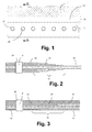
Figur 6 - ein Beispiel für einen Einflussbereich um ein Loch;
-
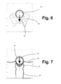
Figur 7 - eine Draufsicht auf den Bereich um ein belastetes
Loch entsprechend Figur 6 mit mehreren unterschiedlichen Versagensformen; - Figur 8
- eine Ausführungsform der Erfindung mit einem größer heraus gezeichneten Detail;
- Figur 9
- eine weitere Ausführungsform der Erfindung.
- FIG. 1
- a plan view of a fiber composite laminate with a joining area with holes and with embedded metal sheets;
- FIG. 2
- a cut through the
FIG. 1 along the line AA in a first alternative; - FIG. 3
- a cut through the
FIG. 1 along the line AA in a second alternative; - FIG. 4
- a FEM simulation of the stress state of a titanium sheet embedded in a fiber composite laminate before the beginning of the first plasticity phenomena;
- FIG. 5
- a FEM simulation of the stress state of a titanium sheet embedded in a fiber composite laminate upon breakage of the joint;
- FIG. 6
- an example of an area of influence around a hole;
- FIG. 7
- a plan view of the area around a loaded hole accordingly
FIG. 6 with several different forms of failure; - FIG. 8
- an embodiment of the invention with a drawn out more detail;
- FIG. 9
- a further embodiment of the invention.
Zunächst soll der grundsätzliche Aufbau und Hintergrund von Verbundwerkstoffen mit Faserverbundschichten und Verstärkungselementen erläutert werden. Die ersten drei Figuren zeigen für den heutigen Stand der Technik typische Ausführungen der lokalen Verstärkung von mechanischen Fügungen an Faserverbundlaminaten mit eingebetteten Metallblechen.First, the basic structure and background of composite materials with fiber composite layers and reinforcing elements will be explained. The first three figures show typical embodiments of the present invention for the local reinforcement of mechanical joints on fiber composite laminates with embedded metal sheets.
Durch den hybriden Bereich 13 sind mehrere Bohrungen 20 geführt. Die Bohrungen 20 verlaufen senkrecht zu der Zeichenebene in
Im hybriden Bereich 13 bestehend aus Faserverbundschichten 31 und Metallschichten oder anderen Verstärkungsschichten 32 wird die eigentliche mechanische Fügung, beispielsweise mit Bolzen 21 in den Bohrungen 20 vorgesehen. Die Verstärkungsschichten 32 sind meist und auch bevorzugt Metallschichten. Grundsätzlich wären aber auch andere Werkstoffe denkbar, die eine verstärkende Wirkung haben und bevorzugt auch die weiteren vorteilhaften Eigenschaften von Metallen besitzen, hier beispielsweise die homogene Ausbildung und die gleichförmige Struktur, die nicht in bestimmten Richtungen unterschiedliche Werte annehmen. In der weiteren Beschreibung ist häufig vereinfachend von "Metallschichten" die Rede, da es sich um die bevorzugte Ausführungsform handelt. Auch dort könnten grundsätzlich aber auch andere Verstärkungsschichten eingesetzt werden.In the
In der
Die mechanische Fügung etwa mittels Bolzen 21 wird auch hier im Bereich 13 des hybriden Materials durchgeführt.The mechanical joining about by means of
Es ist ersichtlich, dass im Stand der Technik bei beiden Ausführungsformen im Bereich der mechanischen Fügung ein Hybridmaterial vorliegt, und zwar bestehend aus Faserverbundschichten 31 und verstärkenden Metallschichten 32, welche homogen und ungestört sind - abgesehen von den Bohrungen für die Aufnahme der Verbindungsbolzen 21.It can be seen that the prior art in both embodiments has a hybrid material in the mechanical joining area, consisting of fiber composite layers 31 and reinforcing
Aus beiden Verläufen ist ersichtlich, dass die Spannungskonzentrationen in einem geringeren Bereich um die belastete Bohrung lokalisiert sind. Diese Spannungskonzentrationen können, je nach Probegeometrie und Laminataufbau, zu unterschiedlichen Versagensformen führen.From both runs it can be seen that the stress concentrations are located in a smaller area around the loaded bore. These stress concentrations can, depending on the sample geometry and laminate structure, lead to different failure modes.
In
Ausgehend von den Spannungskonzentrationen im Einflussbereich können verschiedene Versagensformen auftreten, die in
In
Mindestens eine der Verstärkungsschichten 32 zeigt wie in der
Die Struktur der Perforationen 50, 51 weist unterschiedliche Gestaltengrößen von Perforationen auf, was in der
Es ist auch möglich, verschiedene Strukturen der Bereiche 34, 35, 36 für unterschiedliche Verstärkungsschichten 32 des Verbundwerkstoffes vorzusehen.It is also possible to provide different structures of the
Die Perforationsstruktur kann derart konfiguriert sein, dass ein abnehmender Grad der Zahl und/oder Größe der Ausnehmungen vom niedrig belasteten zum höchstbelasteten, homogenen Bereich hin abnimmt. Der abnehmende Grad der Zahl und/oder Größe der Ausnehmungen kann derart realisiert werden, dass die Packungsdichte der Perforationen 50 abnimmt, wie im Detail A der
Die Gestalt des lokalen homogenen Bereichs, die Form und Art der strukturierten Ausnehmungen kann hierbei von Metallschicht 32 zu Metallschicht 32 im Bereich eines belasteten Loches für einen Bolzen 21 oder zu anderen Zwecken verschieden sein. Auf diese Weise lässt sich die Verstärkung für den gegebenen Fall maßschneidern und folglich die maximale Effizienz der Verstärkung bei Minimierung des Laminatgewichtes erzielen.The shape of the local homogeneous region, the shape and type of the structured recesses may hereby be different from
Eine Ausführungsform für eine kontinuierliche einreihige Fügung des Verbundwerkstoffs mit einer Reihe von Bolzen 21 ist in
Der Perforationen 50, 51 füllen sich ohnehin in der Praxis während der Herstellung des Verbundwerkstoffes mit Harz aus den benachbarten Faserverbundschichten 31 vollständig aus. Auf diese Weise entsteht auch ein zusätzlicher Formschluss zwischen den Faserverbundschichten 31 und der jeweiligen Metallschicht 32 mit den Perforationen 50, 51. Dies stabilisiert den erfindungsgemäßen Verbundwerkstoff zusätzlich.The
- 1111
- Faserverbund-BasislaminatFiber composite base laminate
- 1212
- ÜbergangsbereichTransition area
- 1313
- hybrider Bereichhybrid area
- 2020
- Bohrungdrilling
- 2121
- Bolzenbolt
- 3131
- FaserverbundschichtFiber composite layer
- 3232
- Verstärkungsschicht, insbesondere MetallschichtReinforcing layer, in particular metal layer
- 3333
-
Rand der Metallschicht 32Edge of the
metal layer 32 - 3434
- niedrig belasteter Bereich der Metallschicht 32Low loaded area of the metal layer 32nd
- 3535
- höher belasteter Bereich der Metallschicht 32higher loaded area of the metal layer 32nd
- 3636
-
stark belasteter Bereich der Metallschicht 32heavily loaded area of the
metal layer 32 - 3737
- Richtung einer BelastungDirection of a burden
- 4040
- Wangenbruchcheek fracture
- 4141
- LochleibungsbruchLochleibungsbruch
- 4242
- Scherbruchshear fracture
- 5050
- Perforationperforation
- 5151
- Perforationperforation
Claims (8)
mit Perforationen (50, 51) in der Verstärkungsschicht (32),
dadurch gekennzeichnet,
dass eine oder mehrere Bohrungen (20) durch den Verbundwerkstoff in dem Bereich (13) geführt sind, in welchem die Faserverbundschichten (31) mit einer oder mehreren Verstärkungsschichten (32) versehen sind,
dass die oder zumindest eine der Verstärkungsschichten (32) in einem Bereich (36) um die Bohrung(en) (20) homogen und perforationsfrei ausgebildet ist, und
dass die Verstärkungsschicht (32) in Bereichen (34, 35) außerhalb des Bereiches (36) um die Bohrungen (20) mit Perforationen (50, 51) versehen ist, deren Größe und/oder Zahl pro Fläche in Abhängigkeit vom Beanspruchungszustand der Verstärkungsschicht (32) in den jeweiligen Bereichen (34, 35) ausgebildet ist.Composite material having a plurality of fiber composite layers (31) and a reinforcement region (13) having at least one reinforcement layer (32) of a material reinforcing the fiber composite layers (31), and
with perforations (50, 51) in the reinforcing layer (32),
characterized,
in that one or more bores (20) are guided through the composite material in the region (13) in which the fiber composite layers (31) are provided with one or more reinforcement layers (32),
that the or at least one of the reinforcing layers (32) in a region (36) around the bore (s) (20) is formed homogeneous and perforation-free, and
that the reinforcement layer (32) in areas (34, 35) outside the region (36) around the holes (20) with perforations (50, 51) is provided, the size and / or number per area, depending on the stress state of the reinforcing layer ( 32) in the respective regions (34, 35) is formed.
dadurch gekennzeichnet,
dass die Form des homogen und perforationsfrei ausgebildeten Bereiches (36) um die Bohrungen (20) in Abhängigkeit vom Beanspruchungszustand der Verstärkungsschicht (32) in diesem Bereich (36) ausgebildet ist.Composite comprising a plurality of fiber composite layers according to claim 1,
characterized,
in that the shape of the homogeneous and perforation-free region (36) around the bores (20) is formed as a function of the stress state of the reinforcing layer (32) in this region (36).
dadurch gekennzeichnet,
dass die oder eine der Verstärkungsschichten (32) Metallschichten beziehungsweise Metallbleche sind.Composite comprising a plurality of fiber composite layers according to claim 1 or 2,
characterized,
that the or one of the reinforcement layers (32) are metal layers or metal sheets.
dadurch gekennzeichnet,
dass die oder eine der Verstärkungsschichten (32) aus Stahl, Titan, Kobalt oder Aluminium besteht.Composite comprising a plurality of fiber composite layers according to claim 3,
characterized,
in that the or one of the reinforcing layers (32) consists of steel, titanium, cobalt or aluminum.
dadurch gekennzeichnet,
dass die Perforationen (50, 51) mit bei der Herstellung des Laminats des Verbundwerkstoffs anfallendem Harz befüllt sind.Composite comprising a plurality of fiber composite layers according to one of the preceding claims,
characterized,
in that the perforations (50, 51) are filled with resin produced during the production of the laminate of the composite material.
dadurch gekennzeichnet,
dass Bolzen (21) durch die Bohrung(en) (20) geführt sind, und
dass an den Bolzen Angriffsmöglichkeiten für Kräfte vorgesehen sind.Composite comprising a plurality of fiber composite layers according to one of the preceding claims,
characterized,
that bolts (21) are passed through the bore (s) (20), and
that are provided on the bolt attack possibilities for forces.
dadurch gekennzeichnet,
dass die Perforationen (50, 51) durch Laserverfahren, spanende mechanische Verfahren und/oder Elektronenstrahlverfahren realisiert sind.Composite comprising a plurality of fiber composite layers according to one of the preceding claims,
characterized,
in that the perforations (50, 51) are realized by laser methods, machining mechanical methods and / or electron beam methods.
dadurch gekennzeichnet,
dass die Perforationen (50, 51) einen Durchmesser von bis zu 60 Micrometer aufweisen.Composite comprising a plurality of fiber composite layers according to one of the preceding claims,
characterized,
that the perforations (50, 51) have a diameter of up to 60 microns.
Applications Claiming Priority (1)
| Application Number | Priority Date | Filing Date | Title |
|---|---|---|---|
| DE102010009769A DE102010009769A1 (en) | 2010-03-01 | 2010-03-01 | Composite of several fiber composite layers and a reinforcing region |
Publications (3)
| Publication Number | Publication Date |
|---|---|
| EP2363282A2 true EP2363282A2 (en) | 2011-09-07 |
| EP2363282A3 EP2363282A3 (en) | 2012-08-22 |
| EP2363282B1 EP2363282B1 (en) | 2019-08-28 |
Family
ID=44260399
Family Applications (1)
| Application Number | Title | Priority Date | Filing Date |
|---|---|---|---|
| EP11156210.4A Active EP2363282B1 (en) | 2010-03-01 | 2011-02-28 | Composite substance comprising multiple fibre compound layers and a reinforcement area |
Country Status (2)
| Country | Link |
|---|---|
| EP (1) | EP2363282B1 (en) |
| DE (1) | DE102010009769A1 (en) |
Cited By (2)
| Publication number | Priority date | Publication date | Assignee | Title |
|---|---|---|---|---|
| EP3124221A1 (en) * | 2015-07-27 | 2017-02-01 | Airbus Operations Limited | Composite structure |
| EP3552813A1 (en) * | 2018-04-13 | 2019-10-16 | Deutsches Zentrum für Luft- und Raumfahrt e.V. | Fibre compound component with intermediate layers and method for producing the same |
Families Citing this family (3)
| Publication number | Priority date | Publication date | Assignee | Title |
|---|---|---|---|---|
| EP3006190B1 (en) | 2014-10-08 | 2018-12-05 | AIRBUS HELICOPTERS DEUTSCHLAND GmbH | Composite laminate and load-introduction component for a load-introduction joint |
| DE102018110307A1 (en) * | 2018-04-30 | 2019-10-31 | Airbus Defence and Space GmbH | Composite component and method for producing a composite component |
| DE102022115553A1 (en) | 2022-06-22 | 2023-12-28 | Deutsches Zentrum für Luft- und Raumfahrt e.V. | Method for producing a fiber composite component and fiber composite hollow component and a wind turbine for this purpose |
Citations (8)
| Publication number | Priority date | Publication date | Assignee | Title |
|---|---|---|---|---|
| DE7317520U (en) | 1974-03-14 | Lahmann F | Reinforcement element for introducing forces into foamed plastic parts | |
| US4673606A (en) | 1984-02-14 | 1987-06-16 | Harald Unden | Load-introducing armature as component part of a laminated structural element |
| CH681871A5 (en) | 1990-07-13 | 1993-06-15 | Hydrostress Ag | Equipment for producing back cuts with holes of concrete and stone material - uses material removal tools pressed radially outwards during their rotary movement by use of adjustment body moved linearly hydraulically |
| EP1082217B1 (en) | 1999-03-20 | 2002-06-05 | DLR Deutsches Zentrum für Luft- und Raumfahrt e.V. | Composite material with a reinforced connecting area |
| DE102006000001A1 (en) | 2005-01-11 | 2006-08-24 | Toyota Jidosha K.K., Toyota | Agent apparatus for a vehicle, agent system, agent control method, terminal apparatus, and information providing method |
| US7115323B2 (en) | 2003-08-28 | 2006-10-03 | The Boeing Company | Titanium foil ply replacement in layup of composite skin |
| DE102006000144A1 (en) | 2005-03-30 | 2006-10-05 | Toyota Jidosha K.K., Toyota | Relay defect e.g. melting defect, diagnosing device for e.g. hybrid vehicle, has control unit to detects defect based on determination if capacitor connected to unit is charged or not and to notify defect to driver via alarm lamp |
| DE102006001444A1 (en) | 2006-01-10 | 2007-07-12 | Deutsches Zentrum für Luft- und Raumfahrt e.V. | Reinforced composite material comprising several layers of fibre composite and layers of reinforcing material weakened in the end section by resin-filled holes increasing in size towards the edge of the end |
Family Cites Families (5)
| Publication number | Priority date | Publication date | Assignee | Title |
|---|---|---|---|---|
| FI83791C (en) * | 1989-08-24 | 1991-08-26 | Neste Oy | SLITSTARKT BAND OCH FOERFARANDE FOER FRAMSTAELLNING AV DETTA. |
| JPH0661899B2 (en) * | 1991-02-22 | 1994-08-17 | 新日鐵化学株式会社 | Composite panel manufacturing method |
| JPH06198806A (en) * | 1992-12-28 | 1994-07-19 | Tonen Corp | Prepreg |
| DE19925588A1 (en) * | 1999-06-04 | 2000-12-07 | Deutsch Zentr Luft & Raumfahrt | Thread for connecting fibers of a semifinished fiber product and semifinished fiber product, and method for producing fiber composite materials |
| JP5625260B2 (en) * | 2009-04-21 | 2014-11-19 | 株式会社豊田自動織機 | Fiber reinforced composite material and fastening structure of fiber reinforced composite material |
-
2010
- 2010-03-01 DE DE102010009769A patent/DE102010009769A1/en not_active Withdrawn
-
2011
- 2011-02-28 EP EP11156210.4A patent/EP2363282B1/en active Active
Patent Citations (8)
| Publication number | Priority date | Publication date | Assignee | Title |
|---|---|---|---|---|
| DE7317520U (en) | 1974-03-14 | Lahmann F | Reinforcement element for introducing forces into foamed plastic parts | |
| US4673606A (en) | 1984-02-14 | 1987-06-16 | Harald Unden | Load-introducing armature as component part of a laminated structural element |
| CH681871A5 (en) | 1990-07-13 | 1993-06-15 | Hydrostress Ag | Equipment for producing back cuts with holes of concrete and stone material - uses material removal tools pressed radially outwards during their rotary movement by use of adjustment body moved linearly hydraulically |
| EP1082217B1 (en) | 1999-03-20 | 2002-06-05 | DLR Deutsches Zentrum für Luft- und Raumfahrt e.V. | Composite material with a reinforced connecting area |
| US7115323B2 (en) | 2003-08-28 | 2006-10-03 | The Boeing Company | Titanium foil ply replacement in layup of composite skin |
| DE102006000001A1 (en) | 2005-01-11 | 2006-08-24 | Toyota Jidosha K.K., Toyota | Agent apparatus for a vehicle, agent system, agent control method, terminal apparatus, and information providing method |
| DE102006000144A1 (en) | 2005-03-30 | 2006-10-05 | Toyota Jidosha K.K., Toyota | Relay defect e.g. melting defect, diagnosing device for e.g. hybrid vehicle, has control unit to detects defect based on determination if capacitor connected to unit is charged or not and to notify defect to driver via alarm lamp |
| DE102006001444A1 (en) | 2006-01-10 | 2007-07-12 | Deutsches Zentrum für Luft- und Raumfahrt e.V. | Reinforced composite material comprising several layers of fibre composite and layers of reinforcing material weakened in the end section by resin-filled holes increasing in size towards the edge of the end |
Cited By (2)
| Publication number | Priority date | Publication date | Assignee | Title |
|---|---|---|---|---|
| EP3124221A1 (en) * | 2015-07-27 | 2017-02-01 | Airbus Operations Limited | Composite structure |
| EP3552813A1 (en) * | 2018-04-13 | 2019-10-16 | Deutsches Zentrum für Luft- und Raumfahrt e.V. | Fibre compound component with intermediate layers and method for producing the same |
Also Published As
| Publication number | Publication date |
|---|---|
| EP2363282A3 (en) | 2012-08-22 |
| DE102010009769A1 (en) | 2011-09-01 |
| EP2363282B1 (en) | 2019-08-28 |
Similar Documents
| Publication | Publication Date | Title |
|---|---|---|
| DE10301445B4 (en) | Lightweight structural component, in particular for aircraft and method for its production | |
| EP1735211B1 (en) | Fairing for an aircraft structure | |
| EP2331318B1 (en) | Fiber composite component for energy absorption in the event of a crash for an aircraft or spacecraft, fuselage structural section of an aircraft or spacecraft, and aircraft or spacecraft | |
| EP2363282B1 (en) | Composite substance comprising multiple fibre compound layers and a reinforcement area | |
| EP1312467A1 (en) | Metal fibre reinforced composite material and method of making | |
| DE102010006144B4 (en) | Fairing for an aircraft structure | |
| DE102008024585B4 (en) | Spring element for a spring-damper arrangement | |
| EP1678390A1 (en) | Construction component comprising an auxetic structure | |
| EP3057774B1 (en) | Component having a fastening region for a threaded connection, molded part, and fastening part | |
| EP1666354A1 (en) | Structural component, process for manufacturing a structural component and use of a structural component for an aircraft skin | |
| DE102015014489A1 (en) | Part made of partially hardened sheet steel | |
| WO2006119732A1 (en) | Metal, integral structural component having improved residual strength | |
| DE102010035324A1 (en) | Hybrid laminated structural element useful in aerospace industry, comprises layers such as fiber composite material layers and metallic material layers, where each fiber composite layer has unidirectionally aligned fibers | |
| DE102006001444A1 (en) | Reinforced composite material comprising several layers of fibre composite and layers of reinforcing material weakened in the end section by resin-filled holes increasing in size towards the edge of the end | |
| DE102008052604B4 (en) | Fiber-reinforced composite material and method for producing the same | |
| EP1723317A1 (en) | Lever for a valve control of a piston machine | |
| EP3067448B1 (en) | Method for the production of a heald | |
| EP3242983A1 (en) | Frame-panel formwork element | |
| DE102007016634A1 (en) | Joint element for use in composite structure for connecting e.g. sheet metals, has joint section with tapering cross section rotationally symmetric around central axis of element, which extends in axial direction | |
| WO2014108240A1 (en) | Method for producing a structural component of a vehicle | |
| DE102014202566A1 (en) | A composite part comprising a metal component and a continuous fiber reinforced plastic material component | |
| DE102018105246B4 (en) | Method for producing a reinforced fiber composite material, fiber composite material and aircraft or spacecraft | |
| EP2332721A1 (en) | Compound material | |
| DE102008049257A1 (en) | Connecting rod for reciprocating piston engine, has connecting bars interconnected with longitudinal bars, and recesses formed in connecting rod shank, where bars asymmetrically run in relation to longitudinal plane of connecting rod | |
| DE102021128827A1 (en) | Escalator device with cantilevered truss-type support structure with hybrid material tie rods and method and use |
Legal Events
| Date | Code | Title | Description |
|---|---|---|---|
| PUAI | Public reference made under article 153(3) epc to a published international application that has entered the european phase |
Free format text: ORIGINAL CODE: 0009012 |
|
| AK | Designated contracting states |
Kind code of ref document: A2 Designated state(s): AL AT BE BG CH CY CZ DE DK EE ES FI FR GB GR HR HU IE IS IT LI LT LU LV MC MK MT NL NO PL PT RO RS SE SI SK SM TR |
|
| AX | Request for extension of the european patent |
Extension state: BA ME |
|
| PUAL | Search report despatched |
Free format text: ORIGINAL CODE: 0009013 |
|
| AK | Designated contracting states |
Kind code of ref document: A3 Designated state(s): AL AT BE BG CH CY CZ DE DK EE ES FI FR GB GR HR HU IE IS IT LI LT LU LV MC MK MT NL NO PL PT RO RS SE SI SK SM TR |
|
| AX | Request for extension of the european patent |
Extension state: BA ME |
|
| RIC1 | Information provided on ipc code assigned before grant |
Ipc: B32B 5/24 20060101ALI20120713BHEP Ipc: B32B 15/14 20060101ALI20120713BHEP Ipc: B32B 3/02 20060101ALI20120713BHEP Ipc: B32B 3/10 20060101AFI20120713BHEP Ipc: B32B 7/04 20060101ALI20120713BHEP Ipc: B29C 70/00 20060101ALI20120713BHEP Ipc: B32B 7/08 20060101ALI20120713BHEP Ipc: B32B 7/02 20060101ALI20120713BHEP Ipc: B32B 3/26 20060101ALI20120713BHEP Ipc: B32B 5/26 20060101ALI20120713BHEP Ipc: B32B 15/00 20060101ALI20120713BHEP |
|
| 17P | Request for examination filed |
Effective date: 20130221 |
|
| STAA | Information on the status of an ep patent application or granted ep patent |
Free format text: STATUS: EXAMINATION IS IN PROGRESS |
|
| 17Q | First examination report despatched |
Effective date: 20170914 |
|
| GRAP | Despatch of communication of intention to grant a patent |
Free format text: ORIGINAL CODE: EPIDOSNIGR1 |
|
| STAA | Information on the status of an ep patent application or granted ep patent |
Free format text: STATUS: GRANT OF PATENT IS INTENDED |
|
| INTG | Intention to grant announced |
Effective date: 20190507 |
|
| GRAS | Grant fee paid |
Free format text: ORIGINAL CODE: EPIDOSNIGR3 |
|
| GRAA | (expected) grant |
Free format text: ORIGINAL CODE: 0009210 |
|
| STAA | Information on the status of an ep patent application or granted ep patent |
Free format text: STATUS: THE PATENT HAS BEEN GRANTED |
|
| AK | Designated contracting states |
Kind code of ref document: B1 Designated state(s): AL AT BE BG CH CY CZ DE DK EE ES FI FR GB GR HR HU IE IS IT LI LT LU LV MC MK MT NL NO PL PT RO RS SE SI SK SM TR |
|
| REG | Reference to a national code |
Ref country code: GB Ref legal event code: FG4D Free format text: NOT ENGLISH |
|
| REG | Reference to a national code |
Ref country code: CH Ref legal event code: EP |
|
| REG | Reference to a national code |
Ref country code: AT Ref legal event code: REF Ref document number: 1171894 Country of ref document: AT Kind code of ref document: T Effective date: 20190915 |
|
| REG | Reference to a national code |
Ref country code: IE Ref legal event code: FG4D Free format text: LANGUAGE OF EP DOCUMENT: GERMAN |
|
| REG | Reference to a national code |
Ref country code: DE Ref legal event code: R096 Ref document number: 502011016038 Country of ref document: DE |
|
| REG | Reference to a national code |
Ref country code: NL Ref legal event code: MP Effective date: 20190828 |
|
| REG | Reference to a national code |
Ref country code: LT Ref legal event code: MG4D |
|
| PG25 | Lapsed in a contracting state [announced via postgrant information from national office to epo] |
Ref country code: FI Free format text: LAPSE BECAUSE OF FAILURE TO SUBMIT A TRANSLATION OF THE DESCRIPTION OR TO PAY THE FEE WITHIN THE PRESCRIBED TIME-LIMIT Effective date: 20190828 Ref country code: NO Free format text: LAPSE BECAUSE OF FAILURE TO SUBMIT A TRANSLATION OF THE DESCRIPTION OR TO PAY THE FEE WITHIN THE PRESCRIBED TIME-LIMIT Effective date: 20191128 Ref country code: PT Free format text: LAPSE BECAUSE OF FAILURE TO SUBMIT A TRANSLATION OF THE DESCRIPTION OR TO PAY THE FEE WITHIN THE PRESCRIBED TIME-LIMIT Effective date: 20191230 Ref country code: HR Free format text: LAPSE BECAUSE OF FAILURE TO SUBMIT A TRANSLATION OF THE DESCRIPTION OR TO PAY THE FEE WITHIN THE PRESCRIBED TIME-LIMIT Effective date: 20190828 Ref country code: LT Free format text: LAPSE BECAUSE OF FAILURE TO SUBMIT A TRANSLATION OF THE DESCRIPTION OR TO PAY THE FEE WITHIN THE PRESCRIBED TIME-LIMIT Effective date: 20190828 Ref country code: NL Free format text: LAPSE BECAUSE OF FAILURE TO SUBMIT A TRANSLATION OF THE DESCRIPTION OR TO PAY THE FEE WITHIN THE PRESCRIBED TIME-LIMIT Effective date: 20190828 Ref country code: BG Free format text: LAPSE BECAUSE OF FAILURE TO SUBMIT A TRANSLATION OF THE DESCRIPTION OR TO PAY THE FEE WITHIN THE PRESCRIBED TIME-LIMIT Effective date: 20191128 Ref country code: SE Free format text: LAPSE BECAUSE OF FAILURE TO SUBMIT A TRANSLATION OF THE DESCRIPTION OR TO PAY THE FEE WITHIN THE PRESCRIBED TIME-LIMIT Effective date: 20190828 |
|
| PG25 | Lapsed in a contracting state [announced via postgrant information from national office to epo] |
Ref country code: GR Free format text: LAPSE BECAUSE OF FAILURE TO SUBMIT A TRANSLATION OF THE DESCRIPTION OR TO PAY THE FEE WITHIN THE PRESCRIBED TIME-LIMIT Effective date: 20191129 Ref country code: LV Free format text: LAPSE BECAUSE OF FAILURE TO SUBMIT A TRANSLATION OF THE DESCRIPTION OR TO PAY THE FEE WITHIN THE PRESCRIBED TIME-LIMIT Effective date: 20190828 Ref country code: AL Free format text: LAPSE BECAUSE OF FAILURE TO SUBMIT A TRANSLATION OF THE DESCRIPTION OR TO PAY THE FEE WITHIN THE PRESCRIBED TIME-LIMIT Effective date: 20190828 Ref country code: RS Free format text: LAPSE BECAUSE OF FAILURE TO SUBMIT A TRANSLATION OF THE DESCRIPTION OR TO PAY THE FEE WITHIN THE PRESCRIBED TIME-LIMIT Effective date: 20190828 Ref country code: IS Free format text: LAPSE BECAUSE OF FAILURE TO SUBMIT A TRANSLATION OF THE DESCRIPTION OR TO PAY THE FEE WITHIN THE PRESCRIBED TIME-LIMIT Effective date: 20191228 Ref country code: ES Free format text: LAPSE BECAUSE OF FAILURE TO SUBMIT A TRANSLATION OF THE DESCRIPTION OR TO PAY THE FEE WITHIN THE PRESCRIBED TIME-LIMIT Effective date: 20190828 |
|
| PG25 | Lapsed in a contracting state [announced via postgrant information from national office to epo] |
Ref country code: TR Free format text: LAPSE BECAUSE OF FAILURE TO SUBMIT A TRANSLATION OF THE DESCRIPTION OR TO PAY THE FEE WITHIN THE PRESCRIBED TIME-LIMIT Effective date: 20190828 |
|
| PG25 | Lapsed in a contracting state [announced via postgrant information from national office to epo] |
Ref country code: RO Free format text: LAPSE BECAUSE OF FAILURE TO SUBMIT A TRANSLATION OF THE DESCRIPTION OR TO PAY THE FEE WITHIN THE PRESCRIBED TIME-LIMIT Effective date: 20190828 Ref country code: IT Free format text: LAPSE BECAUSE OF FAILURE TO SUBMIT A TRANSLATION OF THE DESCRIPTION OR TO PAY THE FEE WITHIN THE PRESCRIBED TIME-LIMIT Effective date: 20190828 Ref country code: PL Free format text: LAPSE BECAUSE OF FAILURE TO SUBMIT A TRANSLATION OF THE DESCRIPTION OR TO PAY THE FEE WITHIN THE PRESCRIBED TIME-LIMIT Effective date: 20190828 Ref country code: DK Free format text: LAPSE BECAUSE OF FAILURE TO SUBMIT A TRANSLATION OF THE DESCRIPTION OR TO PAY THE FEE WITHIN THE PRESCRIBED TIME-LIMIT Effective date: 20190828 Ref country code: EE Free format text: LAPSE BECAUSE OF FAILURE TO SUBMIT A TRANSLATION OF THE DESCRIPTION OR TO PAY THE FEE WITHIN THE PRESCRIBED TIME-LIMIT Effective date: 20190828 |
|
| PG25 | Lapsed in a contracting state [announced via postgrant information from national office to epo] |
Ref country code: CZ Free format text: LAPSE BECAUSE OF FAILURE TO SUBMIT A TRANSLATION OF THE DESCRIPTION OR TO PAY THE FEE WITHIN THE PRESCRIBED TIME-LIMIT Effective date: 20190828 Ref country code: SM Free format text: LAPSE BECAUSE OF FAILURE TO SUBMIT A TRANSLATION OF THE DESCRIPTION OR TO PAY THE FEE WITHIN THE PRESCRIBED TIME-LIMIT Effective date: 20190828 Ref country code: SK Free format text: LAPSE BECAUSE OF FAILURE TO SUBMIT A TRANSLATION OF THE DESCRIPTION OR TO PAY THE FEE WITHIN THE PRESCRIBED TIME-LIMIT Effective date: 20190828 Ref country code: IS Free format text: LAPSE BECAUSE OF FAILURE TO SUBMIT A TRANSLATION OF THE DESCRIPTION OR TO PAY THE FEE WITHIN THE PRESCRIBED TIME-LIMIT Effective date: 20200224 |
|
| REG | Reference to a national code |
Ref country code: DE Ref legal event code: R097 Ref document number: 502011016038 Country of ref document: DE |
|
| PLBE | No opposition filed within time limit |
Free format text: ORIGINAL CODE: 0009261 |
|
| STAA | Information on the status of an ep patent application or granted ep patent |
Free format text: STATUS: NO OPPOSITION FILED WITHIN TIME LIMIT |
|
| PG2D | Information on lapse in contracting state deleted |
Ref country code: IS |
|
| 26N | No opposition filed |
Effective date: 20200603 |
|
| PG25 | Lapsed in a contracting state [announced via postgrant information from national office to epo] |
Ref country code: SI Free format text: LAPSE BECAUSE OF FAILURE TO SUBMIT A TRANSLATION OF THE DESCRIPTION OR TO PAY THE FEE WITHIN THE PRESCRIBED TIME-LIMIT Effective date: 20190828 |
|
| REG | Reference to a national code |
Ref country code: CH Ref legal event code: PL |
|
| GBPC | Gb: european patent ceased through non-payment of renewal fee |
Effective date: 20200228 |
|
| REG | Reference to a national code |
Ref country code: BE Ref legal event code: MM Effective date: 20200229 |
|
| PG25 | Lapsed in a contracting state [announced via postgrant information from national office to epo] |
Ref country code: MC Free format text: LAPSE BECAUSE OF FAILURE TO SUBMIT A TRANSLATION OF THE DESCRIPTION OR TO PAY THE FEE WITHIN THE PRESCRIBED TIME-LIMIT Effective date: 20190828 Ref country code: LU Free format text: LAPSE BECAUSE OF NON-PAYMENT OF DUE FEES Effective date: 20200228 |
|
| PG25 | Lapsed in a contracting state [announced via postgrant information from national office to epo] |
Ref country code: CH Free format text: LAPSE BECAUSE OF NON-PAYMENT OF DUE FEES Effective date: 20200229 Ref country code: LI Free format text: LAPSE BECAUSE OF NON-PAYMENT OF DUE FEES Effective date: 20200229 |
|
| PG25 | Lapsed in a contracting state [announced via postgrant information from national office to epo] |
Ref country code: FR Free format text: LAPSE BECAUSE OF NON-PAYMENT OF DUE FEES Effective date: 20200229 Ref country code: GB Free format text: LAPSE BECAUSE OF NON-PAYMENT OF DUE FEES Effective date: 20200228 Ref country code: IE Free format text: LAPSE BECAUSE OF NON-PAYMENT OF DUE FEES Effective date: 20200228 |
|
| PG25 | Lapsed in a contracting state [announced via postgrant information from national office to epo] |
Ref country code: BE Free format text: LAPSE BECAUSE OF NON-PAYMENT OF DUE FEES Effective date: 20200229 |
|
| REG | Reference to a national code |
Ref country code: AT Ref legal event code: MM01 Ref document number: 1171894 Country of ref document: AT Kind code of ref document: T Effective date: 20200228 |
|
| PG25 | Lapsed in a contracting state [announced via postgrant information from national office to epo] |
Ref country code: AT Free format text: LAPSE BECAUSE OF NON-PAYMENT OF DUE FEES Effective date: 20200228 |
|
| PGFP | Annual fee paid to national office [announced via postgrant information from national office to epo] |
Ref country code: DE Payment date: 20210113 Year of fee payment: 11 |
|
| PG25 | Lapsed in a contracting state [announced via postgrant information from national office to epo] |
Ref country code: MT Free format text: LAPSE BECAUSE OF FAILURE TO SUBMIT A TRANSLATION OF THE DESCRIPTION OR TO PAY THE FEE WITHIN THE PRESCRIBED TIME-LIMIT Effective date: 20190828 Ref country code: CY Free format text: LAPSE BECAUSE OF FAILURE TO SUBMIT A TRANSLATION OF THE DESCRIPTION OR TO PAY THE FEE WITHIN THE PRESCRIBED TIME-LIMIT Effective date: 20190828 |
|
| PG25 | Lapsed in a contracting state [announced via postgrant information from national office to epo] |
Ref country code: MK Free format text: LAPSE BECAUSE OF FAILURE TO SUBMIT A TRANSLATION OF THE DESCRIPTION OR TO PAY THE FEE WITHIN THE PRESCRIBED TIME-LIMIT Effective date: 20190828 |
|
| REG | Reference to a national code |
Ref country code: DE Ref legal event code: R119 Ref document number: 502011016038 Country of ref document: DE |
|
| PG25 | Lapsed in a contracting state [announced via postgrant information from national office to epo] |
Ref country code: DE Free format text: LAPSE BECAUSE OF NON-PAYMENT OF DUE FEES Effective date: 20220901 |