EP2363088B1 - Sensors on patient side for a microwave generator - Google Patents
Sensors on patient side for a microwave generator Download PDFInfo
- Publication number
- EP2363088B1 EP2363088B1 EP11001689A EP11001689A EP2363088B1 EP 2363088 B1 EP2363088 B1 EP 2363088B1 EP 11001689 A EP11001689 A EP 11001689A EP 11001689 A EP11001689 A EP 11001689A EP 2363088 B1 EP2363088 B1 EP 2363088B1
- Authority
- EP
- European Patent Office
- Prior art keywords
- generator
- sensor module
- isolation device
- electrosurgical
- energy
- Prior art date
- Legal status (The legal status is an assumption and is not a legal conclusion. Google has not performed a legal analysis and makes no representation as to the accuracy of the status listed.)
- Active
Links
- 238000002955 isolation Methods 0.000 claims description 27
- 230000009977 dual effect Effects 0.000 claims description 9
- 239000003990 capacitor Substances 0.000 claims description 7
- 210000001519 tissue Anatomy 0.000 description 23
- 238000000034 method Methods 0.000 description 16
- 239000000523 sample Substances 0.000 description 13
- 238000002679 ablation Methods 0.000 description 12
- 239000004020 conductor Substances 0.000 description 11
- 238000011282 treatment Methods 0.000 description 8
- 230000005540 biological transmission Effects 0.000 description 5
- 238000010438 heat treatment Methods 0.000 description 4
- 206010028980 Neoplasm Diseases 0.000 description 3
- 201000011510 cancer Diseases 0.000 description 3
- 238000010276 construction Methods 0.000 description 3
- 238000010586 diagram Methods 0.000 description 3
- 230000005670 electromagnetic radiation Effects 0.000 description 3
- 230000004048 modification Effects 0.000 description 3
- 238000012986 modification Methods 0.000 description 3
- 230000005404 monopole Effects 0.000 description 3
- 230000008878 coupling Effects 0.000 description 2
- 238000010168 coupling process Methods 0.000 description 2
- 238000005859 coupling reaction Methods 0.000 description 2
- 239000003989 dielectric material Substances 0.000 description 2
- 201000010099 disease Diseases 0.000 description 2
- 208000037265 diseases, disorders, signs and symptoms Diseases 0.000 description 2
- 230000006870 function Effects 0.000 description 2
- 230000000266 injurious effect Effects 0.000 description 2
- 230000003993 interaction Effects 0.000 description 2
- 230000007246 mechanism Effects 0.000 description 2
- 238000012545 processing Methods 0.000 description 2
- 230000005855 radiation Effects 0.000 description 2
- 206010020843 Hyperthermia Diseases 0.000 description 1
- 239000012190 activator Substances 0.000 description 1
- 210000000481 breast Anatomy 0.000 description 1
- 230000010261 cell growth Effects 0.000 description 1
- 230000015271 coagulation Effects 0.000 description 1
- 238000005345 coagulation Methods 0.000 description 1
- 230000001010 compromised effect Effects 0.000 description 1
- 230000006378 damage Effects 0.000 description 1
- 230000003247 decreasing effect Effects 0.000 description 1
- 238000003745 diagnosis Methods 0.000 description 1
- 230000000694 effects Effects 0.000 description 1
- 210000002216 heart Anatomy 0.000 description 1
- 230000036031 hyperthermia Effects 0.000 description 1
- 238000009217 hyperthermia therapy Methods 0.000 description 1
- 230000002427 irreversible effect Effects 0.000 description 1
- 210000003734 kidney Anatomy 0.000 description 1
- 230000000670 limiting effect Effects 0.000 description 1
- 210000004185 liver Anatomy 0.000 description 1
- 210000004072 lung Anatomy 0.000 description 1
- 230000003211 malignant effect Effects 0.000 description 1
- 238000005259 measurement Methods 0.000 description 1
- 208000007106 menorrhagia Diseases 0.000 description 1
- 210000000056 organ Anatomy 0.000 description 1
- 230000037368 penetrate the skin Effects 0.000 description 1
- 210000002307 prostate Anatomy 0.000 description 1
- 238000001959 radiotherapy Methods 0.000 description 1
- 238000002271 resection Methods 0.000 description 1
- 238000001356 surgical procedure Methods 0.000 description 1
- 238000002560 therapeutic procedure Methods 0.000 description 1
- 230000003685 thermal hair damage Effects 0.000 description 1
- 238000012546 transfer Methods 0.000 description 1
Images
Classifications
-
- A—HUMAN NECESSITIES
- A61—MEDICAL OR VETERINARY SCIENCE; HYGIENE
- A61B—DIAGNOSIS; SURGERY; IDENTIFICATION
- A61B18/00—Surgical instruments, devices or methods for transferring non-mechanical forms of energy to or from the body
- A61B18/18—Surgical instruments, devices or methods for transferring non-mechanical forms of energy to or from the body by applying electromagnetic radiation, e.g. microwaves
- A61B18/1815—Surgical instruments, devices or methods for transferring non-mechanical forms of energy to or from the body by applying electromagnetic radiation, e.g. microwaves using microwaves
-
- A—HUMAN NECESSITIES
- A61—MEDICAL OR VETERINARY SCIENCE; HYGIENE
- A61B—DIAGNOSIS; SURGERY; IDENTIFICATION
- A61B18/00—Surgical instruments, devices or methods for transferring non-mechanical forms of energy to or from the body
- A61B18/04—Surgical instruments, devices or methods for transferring non-mechanical forms of energy to or from the body by heating
- A61B18/12—Surgical instruments, devices or methods for transferring non-mechanical forms of energy to or from the body by heating by passing a current through the tissue to be heated, e.g. high-frequency current
- A61B18/1206—Generators therefor
-
- A—HUMAN NECESSITIES
- A61—MEDICAL OR VETERINARY SCIENCE; HYGIENE
- A61B—DIAGNOSIS; SURGERY; IDENTIFICATION
- A61B17/00—Surgical instruments, devices or methods, e.g. tourniquets
- A61B2017/00017—Electrical control of surgical instruments
- A61B2017/00022—Sensing or detecting at the treatment site
- A61B2017/00026—Conductivity or impedance, e.g. of tissue
-
- A—HUMAN NECESSITIES
- A61—MEDICAL OR VETERINARY SCIENCE; HYGIENE
- A61B—DIAGNOSIS; SURGERY; IDENTIFICATION
- A61B17/00—Surgical instruments, devices or methods, e.g. tourniquets
- A61B2017/00017—Electrical control of surgical instruments
- A61B2017/00022—Sensing or detecting at the treatment site
- A61B2017/00084—Temperature
-
- A—HUMAN NECESSITIES
- A61—MEDICAL OR VETERINARY SCIENCE; HYGIENE
- A61B—DIAGNOSIS; SURGERY; IDENTIFICATION
- A61B18/00—Surgical instruments, devices or methods for transferring non-mechanical forms of energy to or from the body
- A61B2018/00636—Sensing and controlling the application of energy
- A61B2018/00642—Sensing and controlling the application of energy with feedback, i.e. closed loop control
-
- A—HUMAN NECESSITIES
- A61—MEDICAL OR VETERINARY SCIENCE; HYGIENE
- A61B—DIAGNOSIS; SURGERY; IDENTIFICATION
- A61B18/00—Surgical instruments, devices or methods for transferring non-mechanical forms of energy to or from the body
- A61B2018/00636—Sensing and controlling the application of energy
- A61B2018/00696—Controlled or regulated parameters
- A61B2018/00702—Power or energy
-
- A—HUMAN NECESSITIES
- A61—MEDICAL OR VETERINARY SCIENCE; HYGIENE
- A61B—DIAGNOSIS; SURGERY; IDENTIFICATION
- A61B18/00—Surgical instruments, devices or methods for transferring non-mechanical forms of energy to or from the body
- A61B2018/00636—Sensing and controlling the application of energy
- A61B2018/00773—Sensed parameters
- A61B2018/00791—Temperature
-
- A—HUMAN NECESSITIES
- A61—MEDICAL OR VETERINARY SCIENCE; HYGIENE
- A61B—DIAGNOSIS; SURGERY; IDENTIFICATION
- A61B18/00—Surgical instruments, devices or methods for transferring non-mechanical forms of energy to or from the body
- A61B2018/00636—Sensing and controlling the application of energy
- A61B2018/00773—Sensed parameters
- A61B2018/00827—Current
-
- A—HUMAN NECESSITIES
- A61—MEDICAL OR VETERINARY SCIENCE; HYGIENE
- A61B—DIAGNOSIS; SURGERY; IDENTIFICATION
- A61B18/00—Surgical instruments, devices or methods for transferring non-mechanical forms of energy to or from the body
- A61B2018/00636—Sensing and controlling the application of energy
- A61B2018/00773—Sensed parameters
- A61B2018/00869—Phase
-
- A—HUMAN NECESSITIES
- A61—MEDICAL OR VETERINARY SCIENCE; HYGIENE
- A61B—DIAGNOSIS; SURGERY; IDENTIFICATION
- A61B18/00—Surgical instruments, devices or methods for transferring non-mechanical forms of energy to or from the body
- A61B2018/00636—Sensing and controlling the application of energy
- A61B2018/00773—Sensed parameters
- A61B2018/00875—Resistance or impedance
-
- A—HUMAN NECESSITIES
- A61—MEDICAL OR VETERINARY SCIENCE; HYGIENE
- A61B—DIAGNOSIS; SURGERY; IDENTIFICATION
- A61B18/00—Surgical instruments, devices or methods for transferring non-mechanical forms of energy to or from the body
- A61B2018/00636—Sensing and controlling the application of energy
- A61B2018/00773—Sensed parameters
- A61B2018/00892—Voltage
-
- A—HUMAN NECESSITIES
- A61—MEDICAL OR VETERINARY SCIENCE; HYGIENE
- A61B—DIAGNOSIS; SURGERY; IDENTIFICATION
- A61B18/00—Surgical instruments, devices or methods for transferring non-mechanical forms of energy to or from the body
- A61B18/18—Surgical instruments, devices or methods for transferring non-mechanical forms of energy to or from the body by applying electromagnetic radiation, e.g. microwaves
- A61B18/1815—Surgical instruments, devices or methods for transferring non-mechanical forms of energy to or from the body by applying electromagnetic radiation, e.g. microwaves using microwaves
- A61B2018/1892—Details of electrical isolations of the antenna
Definitions
- the present disclosure relates generally to microwave ablation procedures that utilize microwave surgical devices having a microwave antenna which may be inserted directly into tissue for diagnosis and treatment of diseases. More particularly, the present disclosure is directed to measuring tissue impedance during a microwave ablation procedure.
- One non-invasive procedure generally involves the treatment of tissue (e.g., a tumor) underlying the skin via the use of microwave energy.
- tissue e.g., a tumor
- the microwave energy is able to non-invasively penetrate the skin to reach the underlying tissue.
- this non-invasive procedure may result in the unwanted heating of healthy tissue.
- the non-invasive use of microwave energy requires a great deal of control.
- microwave probes there are several types of microwave probes in use, e.g., monopole, dipole, and helical.
- One type is a monopole antenna probe, which consists of a single, elongated microwave conductor exposed at the end of the probe. The probe is typically surrounded by a dielectric sleeve.
- the second type of microwave probe commonly used is a dipole antenna, which consists of a coaxial construction having an inner conductor and an outer conductor with a dielectric junction separating a portion of the inner conductor.
- the inner conductor may be coupled to a portion corresponding to a first dipole radiating portion, and a portion of the outer conductor may be coupled to a second dipole radiating portion.
- the dipole radiating portions may be configured such that one radiating portion is located proximally of the dielectric junction, and the other portion is located distally of the dielectric junction.
- microwave energy generally radiates perpendicularly from the axis of the conductor.
- the typical microwave antenna has a long, thin inner conductor that extends along the axis of the probe and is surrounded by a dielectric material and is further surrounded by an outer conductor around the dielectric material such that the outer conductor also extends along the axis of the probe.
- a portion or portions of the outer conductor can be selectively removed.
- This type of construction is typically referred to as a "leaky waveguide” or “leaky coaxial" antenna.
- Another variation on the microwave probe involves having the tip formed in a uniform spiral pattern, such as a helix, to provide the necessary configuration for effective radiation. This variation can be used to direct energy in a particular direction, e.g., perpendicular to the axis, in a forward direction (i.e., towards the distal end of the antenna), or combinations thereof.
- Invasive procedures and devices have been developed in which a microwave antenna probe may be either inserted directly into a point of treatment via a normal body orifice or percutaneously inserted. Such invasive procedures and devices potentially provide better temperature control of the tissue being treated. Because of the small difference between the temperature required for denaturing malignant cells and the temperature injurious to healthy cells, a known heating pattern and predictable temperature control is important so that heating is confmed to the tissue to be treated. For instance, hyperthermia treatment at the threshold temperature of about 41.5°C generally has little effect on most malignant growth of cells. However, at slightly elevated temperatures above the approximate range of 43°C to 45°C, thermal damage to most types of normal cells is routinely observed. Accordingly, great care must be taken not to exceed these temperatures in healthy tissue.
- sensors are utilized to measure and determine various properties of the affected tissue region and/or the ablation system.
- such sensors tend to be on the ground reference side and are not referenced to the patient. Accordingly, the accuracy of the sensors can be compromised due to the isolation boundary from the ground referenced side to the patient, especially if phase is being measured.
- Even the type of isolation boundary may cause inaccuracies in sensor readings. For instance, if capacitors are used as the isolation boundary, the tolerance and/or mechanical mounting of the capacitors may cause phase and impedance variations that affect the sensors. If a coupling mechanism is used as the isolation boundary, it may be difficult to have a repeatable coupling from device to device thereby leading to inaccurate sensor readings.
- the present disclosure relates to an electrosurgical system provided for use in electrosurgical procedures.
- the system includes a generator configured to provide electrosurgical energy to an instrument and a dual directional coupler coupled between the generator and the instrument and configured to sample the electrosurgical energy.
- the system also includes a sensor module configured to detect one or more properties of the sampled electrosurgical energy, a controller configured to receive the detected one or more properties and configured to control the output of the generator based on the detected one or more properties, and an isolation device coupled between the sensor module and the controller.
- the sensor module detects at least one of a phase, forward voltage or reflected voltage.
- the isolation device may include one or more capacitors or one or more transformers.
- the electrosurgical system may include an analog to digital converter operatively coupled between the sensor module and the isolation device where the isolation device may be an opto-coupler.
- Fig. 1 is a schematic block diagram of an electrosurgical system according to an embodiment of the present disclosure.
- Fig. 2 is a schematic block diagram of an electrosurgical system according to another embodiment of the present disclosure. The embodiment shown in figure 2 is not part of the invention.
- Electromagnetic energy is generally classified by increasing energy or decreasing wavelength into radio waves, microwaves, infrared, visible light, ultraviolet, X-rays and gamma-rays.
- microwave generally refers to electromagnetic waves in the frequency range of 300 megahertz (MHz) (3 x 10 8 cycles/second) to 300 gigahertz (GHz) (3 x 10 11 cycles/second).
- RF generally refers to electromagnetic waves having a lower frequency than microwaves.
- ablation procedure generally refers to any ablation procedure, such as RF or microwave ablation or microwave ablation assisted resection.
- transmission line generally refers to any transmission medium that can be used for the propagation of signals from one point to another.
- the present disclosure is directed to an electrosurgical system for use in performing a medical procedure. Such a system is described in document EP-A-2014249 .
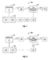
- Fig. 1 is a schematic block diagram of an electrosurgical system 100 according to an embodiment of the present disclosure.
- System 100 may include a generator 102 that supplies electromagnetic energy, e.g., microwave of RF energy, to an energy delivering implement or instrument 130 (e.g., an electrosurgical pencil, a microwave ablation antenna, etc.) via a transmission line 140 (e.g., a coaxial cable) or the like.
- electromagnetic energy e.g., microwave of RF energy
- an energy delivering implement or instrument 130 e.g., an electrosurgical pencil, a microwave ablation antenna, etc.
- a transmission line 140 e.g., a coaxial cable
- the generator 102 includes suitable input controls (e.g., buttons, activators, switches, touch screen, etc.) for controlling the generator 102, as well as one or more display screens for providing the surgeon with variety of output information (e.g., intensity settings, treatment complete indicators, etc.).
- the controls allow the surgeon to adjust power of the energy, waveform, and other parameters to achieve the desired waveform suitable for a particular task (e.g., tissue ablation).
- the instrument 130 may include a plurality of input controls which may be redundant with certain input controls of the generator 102. Placing the input controls at the instrument 130 allows for easier and faster modification of energy parameters during the surgical procedure without requiring interaction with the generator 102.
- System 100 also includes a dual directional coupler 104 operatively coupled between generator 102 and instrument 130. Dual directional coupler 104 is used to sample the forward and reflected energy in system 100.
- An isolation device 106 is provided between generator 102 and dual directional coupler 104 to isolate the generator 102 from a patient. Isolation device may be discrete components such as a capacitor(s) or transformer or it may be built into transmission line 140.
- the sensor module 112 may include a plurality of sensors (not explicitly shown) strategically located for sensing various properties or conditions, e.g., tissue impedance, voltage at the tissue site, current at the tissue site, etc.
- the sensors are provided with leads (or wireless) for transmitting information to the controller 120.
- the sensor module 112 may include control circuitry that receives information from multiple sensors, and provides the information and the source of the information (e.g., the particular sensor providing the information) to the controller 120.
- the sensor module 112 may include a real-time voltage sensing system (not explicitly shown) and a real-time current sensing system (not explicitly shown) for sensing real-time values related to applied voltage and current at the surgical site. Additionally, an RMS voltage sensing system (not explicitly shown) and an RMS current sensing system (not explicitly shown) may be included for sensing and deriving RMS values for applied voltage and current at the surgical site.
- the controller 120 includes a microprocessor 122 having a memory 124 which may be volatile type memory (e.g., RAM) and/or non-volatile type memory (e.g., flash media, disk media, etc.).
- the microprocessor 122 includes an output port connected to the generator 102 that allows the microprocessor 122 to control the output of the generator 102 according to either open and/or closed control loop schemes.
- a closed loop control scheme generally includes a feedback control loop wherein the sensor module 112 provides feedback to the controller 120 (i.e., information obtained from one or more sensing mechanisms for sensing various parameters such as tissue impedance, tissue temperature, forward and reflected current and/or voltage, etc.).
- the controller 120 then signals the generator 102 which then adjusts the output electromagnetic energy.
- the controller 120 also receives input signals from the input controls of the generator 102 and/or instrument 130.
- the controller 120 utilizes the input signals to adjust the power output of the generator 102 and/or instructs the generator 102 to perform other control functions.
- the microprocessor 122 is capable of executing software instructions for processing data received by the sensor module 112, and for outputting control signals to the generator 102, accordingly.
- the software instructions, which are executable by the controller 120, are stored in the memory 124 of the controller 120.
- Sensor module 112 provides a signal that is indicative of the various sensed properties or conditions to an analog to digital converter (ADC) 116 to convert the signal to a digital signal.
- ADC analog to digital converter
- the digital signal is sent to isolation device 114 which conveys the signal to controller 120.
- Isolation device 114 may be an opto-coupler used to transmit information or data from the patient side to the generator side.
- Sensor module 112 is on the patient side and may be configured to convert the signal to digital to go across the isolation boundary provided by isolation device 114.
- the controller 120 may include analog and/or logic circuitry for processing the sensed values and determining the control signals that are sent to the generator 102, rather than, or in combination with, the microprocessor 122.
- Isolation device 114 is coupled between sensor module 112 and controller 120. Isolation device 114 provides electrical isolation between the patient and generator 102. By moving the sensors to the patient side, the interaction between dual directional coupler 104 and the isolation boundary is removed. This allows for a more accurate measurement of phase, forward and reflected voltages. Additionally, any tolerance issue with the isolation boundary does not affect the sensors. Isolation device 114 may be a capacitor, opto-coupler or a transformer.
- system 100 may be included in a single device or may be separate components that are operatively connected to each other.
- Electrosurgical system 200 includes components similar to electrosurgical system 100 which are described in more detail above and will not be repeated hereinbelow.
- sensor module 212 may include a plurality of sensors (not explicitly shown) strategically located for sensing various properties or conditions, e.g., tissue impedance, voltage at the tissue site, current at the tissue site, etc.
- System 200 uses an isolation device 214, such as a capacitor or transformer, to transfer the dual directional coupler signals to the reference of the generator.
- the isolation device 214 is provided between dual directional coupler 104 and sensor module 212.
- the sensor module 212 no longer needs to convert the signal to digital as in system 100. However, sensor module 212 may digitize the signal if desired or necessary.
Landscapes
- Health & Medical Sciences (AREA)
- Surgery (AREA)
- Life Sciences & Earth Sciences (AREA)
- Biomedical Technology (AREA)
- Medical Informatics (AREA)
- Nuclear Medicine, Radiotherapy & Molecular Imaging (AREA)
- Electromagnetism (AREA)
- Engineering & Computer Science (AREA)
- Physics & Mathematics (AREA)
- Heart & Thoracic Surgery (AREA)
- Otolaryngology (AREA)
- Molecular Biology (AREA)
- Animal Behavior & Ethology (AREA)
- General Health & Medical Sciences (AREA)
- Public Health (AREA)
- Veterinary Medicine (AREA)
- Surgical Instruments (AREA)
Description
- The present disclosure relates generally to microwave ablation procedures that utilize microwave surgical devices having a microwave antenna which may be inserted directly into tissue for diagnosis and treatment of diseases. More particularly, the present disclosure is directed to measuring tissue impedance during a microwave ablation procedure.
- In the treatment of diseases such as cancer, certain types of cancer cells have been found to denature at elevated temperatures (which are slightly lower than temperatures normally injurious to healthy cells.) These types of treatments, known generally as hyperthermia therapy, typically utilize electromagnetic radiation to heat diseased cells to temperatures above 41°C, while maintaining adjacent healthy cells at lower temperatures where irreversible cell destruction will not occur. Other procedures utilizing electromagnetic radiation to heat tissue also include ablation and coagulation of the tissue. Such ablation procedures, e.g., such as those performed for menorrhagia, are typically done to ablate and coagulate the targeted tissue to denature or kill the tissue. Many procedures and types of devices utilizing electromagnetic radiation therapy are known in the art. Such microwave therapy is typically used in the treatment of tissue and organs such as the prostate, heart, liver, lung, kidney, and breast.
- One non-invasive procedure generally involves the treatment of tissue (e.g., a tumor) underlying the skin via the use of microwave energy. The microwave energy is able to non-invasively penetrate the skin to reach the underlying tissue. However, this non-invasive procedure may result in the unwanted heating of healthy tissue. Thus, the non-invasive use of microwave energy requires a great deal of control.
- Presently, there are several types of microwave probes in use, e.g., monopole, dipole, and helical. One type is a monopole antenna probe, which consists of a single, elongated microwave conductor exposed at the end of the probe. The probe is typically surrounded by a dielectric sleeve. The second type of microwave probe commonly used is a dipole antenna, which consists of a coaxial construction having an inner conductor and an outer conductor with a dielectric junction separating a portion of the inner conductor. The inner conductor may be coupled to a portion corresponding to a first dipole radiating portion, and a portion of the outer conductor may be coupled to a second dipole radiating portion. The dipole radiating portions may be configured such that one radiating portion is located proximally of the dielectric junction, and the other portion is located distally of the dielectric junction. In the monopole and dipole antenna probe, microwave energy generally radiates perpendicularly from the axis of the conductor.
- The typical microwave antenna has a long, thin inner conductor that extends along the axis of the probe and is surrounded by a dielectric material and is further surrounded by an outer conductor around the dielectric material such that the outer conductor also extends along the axis of the probe. In another variation of the probe that provides for effective outward radiation of energy or heating, a portion or portions of the outer conductor can be selectively removed. This type of construction is typically referred to as a "leaky waveguide" or "leaky coaxial" antenna. Another variation on the microwave probe involves having the tip formed in a uniform spiral pattern, such as a helix, to provide the necessary configuration for effective radiation. This variation can be used to direct energy in a particular direction, e.g., perpendicular to the axis, in a forward direction (i.e., towards the distal end of the antenna), or combinations thereof.
- Invasive procedures and devices have been developed in which a microwave antenna probe may be either inserted directly into a point of treatment via a normal body orifice or percutaneously inserted. Such invasive procedures and devices potentially provide better temperature control of the tissue being treated. Because of the small difference between the temperature required for denaturing malignant cells and the temperature injurious to healthy cells, a known heating pattern and predictable temperature control is important so that heating is confmed to the tissue to be treated. For instance, hyperthermia treatment at the threshold temperature of about 41.5°C generally has little effect on most malignant growth of cells. However, at slightly elevated temperatures above the approximate range of 43°C to 45°C, thermal damage to most types of normal cells is routinely observed. Accordingly, great care must be taken not to exceed these temperatures in healthy tissue.
- In order to achieve better control during ablation procedures, sensors are utilized to measure and determine various properties of the affected tissue region and/or the ablation system. Typically, such sensors tend to be on the ground reference side and are not referenced to the patient. Accordingly, the accuracy of the sensors can be compromised due to the isolation boundary from the ground referenced side to the patient, especially if phase is being measured. Even the type of isolation boundary may cause inaccuracies in sensor readings. For instance, if capacitors are used as the isolation boundary, the tolerance and/or mechanical mounting of the capacitors may cause phase and impedance variations that affect the sensors. If a coupling mechanism is used as the isolation boundary, it may be difficult to have a repeatable coupling from device to device thereby leading to inaccurate sensor readings.
- Document
EP-A-2014249 discloses the most relevant prior art. - The present disclosure, relates to an electrosurgical system provided for use in electrosurgical procedures. The system includes a generator configured to provide electrosurgical energy to an instrument and a dual directional coupler coupled between the generator and the instrument and configured to sample the electrosurgical energy. The system also includes a sensor module configured to detect one or more properties of the sampled electrosurgical energy, a controller configured to receive the detected one or more properties and configured to control the output of the generator based on the detected one or more properties, and an isolation device coupled between the sensor module and the controller.
- The sensor module detects at least one of a phase, forward voltage or reflected voltage. The isolation device may include one or more capacitors or one or more transformers.
- In another embodiment, the electrosurgical system may include an analog to digital converter operatively coupled between the sensor module and the isolation device where the isolation device may be an opto-coupler.
- The above and other aspects, features, and advantages of the present disclosure will become more apparent in light of the following detailed description when taken in conjunction with the accompanying drawings in which:
-
Fig. 1 is a schematic block diagram of an electrosurgical system according to an embodiment of the present disclosure; and -
Fig. 2 is a schematic block diagram of an electrosurgical system according to another embodiment of the present disclosure. The embodiment shown infigure 2 is not part of the invention. - Particular embodiments of the present disclosure are described hereinbelow with reference to the accompanying drawings; however, it is to be understood that the disclosed embodiments are merely exemplary of the disclosure and may be embodied in various forms. Well-known functions or constructions are not described in detail to avoid obscuring the present disclosure in unnecessary detail. Therefore, specific structural and functional details disclosed herein are not to be interpreted as limiting, but merely as a basis for the claims and as a representative basis for teaching one skilled in the art to variously employ the present disclosure in virtually any appropriately detailed structure. Like reference numerals may refer to similar or identical elements throughout the description of the figures.
- Electromagnetic energy is generally classified by increasing energy or decreasing wavelength into radio waves, microwaves, infrared, visible light, ultraviolet, X-rays and gamma-rays. As used herein, the term "microwave" generally refers to electromagnetic waves in the frequency range of 300 megahertz (MHz) (3 x 10⁸ cycles/second) to 300 gigahertz (GHz) (3 x 10¹¹ cycles/second). As used herein, the term "RF" generally refers to electromagnetic waves having a lower frequency than microwaves. The phrase "ablation procedure" generally refers to any ablation procedure, such as RF or microwave ablation or microwave ablation assisted resection. The phrase "transmission line" generally refers to any transmission medium that can be used for the propagation of signals from one point to another.
- The present disclosure is directed to an electrosurgical system for use in performing a medical procedure. Such a system is described in document
EP-A-2014249 . -
Fig. 1 is a schematic block diagram of anelectrosurgical system 100 according to an embodiment of the present disclosure.System 100 may include agenerator 102 that supplies electromagnetic energy, e.g., microwave of RF energy, to an energy delivering implement or instrument 130 (e.g., an electrosurgical pencil, a microwave ablation antenna, etc.) via a transmission line 140 (e.g., a coaxial cable) or the like. - Not explicitly shown in
Fig. 1 , thegenerator 102 includes suitable input controls (e.g., buttons, activators, switches, touch screen, etc.) for controlling thegenerator 102, as well as one or more display screens for providing the surgeon with variety of output information (e.g., intensity settings, treatment complete indicators, etc.). The controls allow the surgeon to adjust power of the energy, waveform, and other parameters to achieve the desired waveform suitable for a particular task (e.g., tissue ablation). Further, theinstrument 130 may include a plurality of input controls which may be redundant with certain input controls of thegenerator 102. Placing the input controls at theinstrument 130 allows for easier and faster modification of energy parameters during the surgical procedure without requiring interaction with thegenerator 102. -
System 100 also includes a dualdirectional coupler 104 operatively coupled betweengenerator 102 andinstrument 130. Dualdirectional coupler 104 is used to sample the forward and reflected energy insystem 100. Anisolation device 106 is provided betweengenerator 102 and dualdirectional coupler 104 to isolate thegenerator 102 from a patient. Isolation device may be discrete components such as a capacitor(s) or transformer or it may be built intotransmission line 140. - Forward energy and reflected energy sampled by dual
directional coupler 104 is provided tosensor module 112 via transmission lines 108 and 110, respectively. Thesensor module 112 may include a plurality of sensors (not explicitly shown) strategically located for sensing various properties or conditions, e.g., tissue impedance, voltage at the tissue site, current at the tissue site, etc. The sensors are provided with leads (or wireless) for transmitting information to thecontroller 120. Thesensor module 112 may include control circuitry that receives information from multiple sensors, and provides the information and the source of the information (e.g., the particular sensor providing the information) to thecontroller 120. - More particularly, the
sensor module 112 may include a real-time voltage sensing system (not explicitly shown) and a real-time current sensing system (not explicitly shown) for sensing real-time values related to applied voltage and current at the surgical site. Additionally, an RMS voltage sensing system (not explicitly shown) and an RMS current sensing system (not explicitly shown) may be included for sensing and deriving RMS values for applied voltage and current at the surgical site. - The
controller 120 includes amicroprocessor 122 having amemory 124 which may be volatile type memory (e.g., RAM) and/or non-volatile type memory (e.g., flash media, disk media, etc.). Themicroprocessor 122 includes an output port connected to thegenerator 102 that allows themicroprocessor 122 to control the output of thegenerator 102 according to either open and/or closed control loop schemes. - A closed loop control scheme generally includes a feedback control loop wherein the
sensor module 112 provides feedback to the controller 120 (i.e., information obtained from one or more sensing mechanisms for sensing various parameters such as tissue impedance, tissue temperature, forward and reflected current and/or voltage, etc.). Thecontroller 120 then signals thegenerator 102 which then adjusts the output electromagnetic energy. Thecontroller 120 also receives input signals from the input controls of thegenerator 102 and/orinstrument 130. Thecontroller 120 utilizes the input signals to adjust the power output of thegenerator 102 and/or instructs thegenerator 102 to perform other control functions. - The
microprocessor 122 is capable of executing software instructions for processing data received by thesensor module 112, and for outputting control signals to thegenerator 102, accordingly. The software instructions, which are executable by thecontroller 120, are stored in thememory 124 of thecontroller 120. -
Sensor module 112 provides a signal that is indicative of the various sensed properties or conditions to an analog to digital converter (ADC) 116 to convert the signal to a digital signal. The digital signal is sent toisolation device 114 which conveys the signal tocontroller 120.Isolation device 114 may be an opto-coupler used to transmit information or data from the patient side to the generator side.Sensor module 112 is on the patient side and may be configured to convert the signal to digital to go across the isolation boundary provided byisolation device 114. - The
controller 120 may include analog and/or logic circuitry for processing the sensed values and determining the control signals that are sent to thegenerator 102, rather than, or in combination with, themicroprocessor 122. - An
isolation device 114 is coupled betweensensor module 112 andcontroller 120.Isolation device 114 provides electrical isolation between the patient andgenerator 102. By moving the sensors to the patient side, the interaction between dualdirectional coupler 104 and the isolation boundary is removed. This allows for a more accurate measurement of phase, forward and reflected voltages. Additionally, any tolerance issue with the isolation boundary does not affect the sensors.Isolation device 114 may be a capacitor, opto-coupler or a transformer. - It should be noted that the components of
system 100 described hereinabove may be included in a single device or may be separate components that are operatively connected to each other. - Turning to
Fig. 2 , an electrosurgical system according to another embodiment of the present disclosure is shown generally as 200.Electrosurgical system 200 includes components similar toelectrosurgical system 100 which are described in more detail above and will not be repeated hereinbelow. Similar tosensor module 112,sensor module 212 may include a plurality of sensors (not explicitly shown) strategically located for sensing various properties or conditions, e.g., tissue impedance, voltage at the tissue site, current at the tissue site, etc.System 200 uses anisolation device 214, such as a capacitor or transformer, to transfer the dual directional coupler signals to the reference of the generator. Theisolation device 214 is provided between dualdirectional coupler 104 andsensor module 212. Thesensor module 212 no longer needs to convert the signal to digital as insystem 100. However,sensor module 212 may digitize the signal if desired or necessary. - It should be understood that the foregoing description is only illustrative of the present disclosure. Various alternatives and modifications can be devised by those skilled in the art without departing from the disclosure. Accordingly, the present disclosure is intended to embrace all such alternatives, modifications and variances. The embodiments described with reference to the attached drawing figs. are presented only to demonstrate certain examples of the disclosure. Other elements, steps, methods and techniques that are insubstantially different from those described above and/or in the appended claims are also intended to be within the scope of the disclosure.
Claims (6)
- An electrosurgical system (100), comprising:a generator (102) configured to provide electrosurgical energy to an instrument;a dual directional coupler (104) coupled between the generator and the instrument and configured to sample the electrosurgical energy;a sensor module (112) configured to detect at least one property of the sampled electrosurgical energy;a controller (120) configured to receive the detected at least one property and configured to control the output of the generator based on the detected at least one property; characterized byan isolation device (114) coupled between the sensor module and the controller.
- The electrosurgical system according to claim 1, wherein the sensor module detects at least one of a phase, forward voltage or reflected voltage.
- The electrosurgical system according to claim 1, wherein the isolation device includes at least one capacitor.
- The electrosurgical system according to claim 1, wherein the isolation device includes at least one transformer.
- The electrosurgical system according to claim 1, further comprising an analog to digital converter operatively coupled between the sensor module and the isolation device.
- The electrosurgical system according to claim 5, wherein the isolation device includes at least one opto-coupler.
Applications Claiming Priority (1)
| Application Number | Priority Date | Filing Date | Title |
|---|---|---|---|
| US12/715,212 US20110213355A1 (en) | 2010-03-01 | 2010-03-01 | Sensors On Patient Side for a Microwave Generator |
Publications (2)
| Publication Number | Publication Date |
|---|---|
| EP2363088A1 EP2363088A1 (en) | 2011-09-07 |
| EP2363088B1 true EP2363088B1 (en) | 2012-09-19 |
Family
ID=44175972
Family Applications (1)
| Application Number | Title | Priority Date | Filing Date |
|---|---|---|---|
| EP11001689A Active EP2363088B1 (en) | 2010-03-01 | 2011-03-01 | Sensors on patient side for a microwave generator |
Country Status (3)
| Country | Link |
|---|---|
| US (1) | US20110213355A1 (en) |
| EP (1) | EP2363088B1 (en) |
| JP (1) | JP2011177512A (en) |
Families Citing this family (15)
| Publication number | Priority date | Publication date | Assignee | Title |
|---|---|---|---|---|
| US7137980B2 (en) | 1998-10-23 | 2006-11-21 | Sherwood Services Ag | Method and system for controlling output of RF medical generator |
| AU2004235739B2 (en) | 2003-05-01 | 2010-06-17 | Covidien Ag | Method and system for programming and controlling an electrosurgical generator system |
| US8104956B2 (en) | 2003-10-23 | 2012-01-31 | Covidien Ag | Thermocouple measurement circuit |
| US7396336B2 (en) | 2003-10-30 | 2008-07-08 | Sherwood Services Ag | Switched resonant ultrasonic power amplifier system |
| US7947039B2 (en) | 2005-12-12 | 2011-05-24 | Covidien Ag | Laparoscopic apparatus for performing electrosurgical procedures |
| CA2574934C (en) | 2006-01-24 | 2015-12-29 | Sherwood Services Ag | System and method for closed loop monitoring of monopolar electrosurgical apparatus |
| US8262652B2 (en) | 2009-01-12 | 2012-09-11 | Tyco Healthcare Group Lp | Imaginary impedance process monitoring and intelligent shut-off |
| US8454590B2 (en) * | 2010-02-26 | 2013-06-04 | Covidien Lp | Enhanced lossless current sense circuit |
| US8636730B2 (en) * | 2010-07-12 | 2014-01-28 | Covidien Lp | Polarity control of electrosurgical generator |
| US10376301B2 (en) * | 2011-09-28 | 2019-08-13 | Covidien Lp | Logarithmic amplifier, electrosurgical generator including same, and method of controlling electrosurgical generator using same |
| US8968290B2 (en) | 2012-03-14 | 2015-03-03 | Covidien Lp | Microwave ablation generator control system |
| US9106270B2 (en) * | 2012-10-02 | 2015-08-11 | Covidien Lp | Transmitting data across a patient isolation barrier using an electric-field capacitive coupler module |
| US9872719B2 (en) | 2013-07-24 | 2018-01-23 | Covidien Lp | Systems and methods for generating electrosurgical energy using a multistage power converter |
| US9636165B2 (en) | 2013-07-29 | 2017-05-02 | Covidien Lp | Systems and methods for measuring tissue impedance through an electrosurgical cable |
| US11712295B2 (en) * | 2019-12-30 | 2023-08-01 | Biosense Webster (Israel) Ltd. | Multi-purpose sensing and radiofrequency (RF) ablation spiral electrode for catheter |
Family Cites Families (13)
| Publication number | Priority date | Publication date | Assignee | Title |
|---|---|---|---|---|
| US5385544A (en) * | 1992-08-12 | 1995-01-31 | Vidamed, Inc. | BPH ablation method and apparatus |
| US5961871A (en) * | 1991-11-14 | 1999-10-05 | Lockheed Martin Energy Research Corporation | Variable frequency microwave heating apparatus |
| US5693082A (en) * | 1993-05-14 | 1997-12-02 | Fidus Medical Technology Corporation | Tunable microwave ablation catheter system and method |
| JPH10118093A (en) * | 1996-10-23 | 1998-05-12 | Olympus Optical Co Ltd | High-frequency current curing apparatus |
| US6067475A (en) * | 1998-11-05 | 2000-05-23 | Urologix, Inc. | Microwave energy delivery system including high performance dual directional coupler for precisely measuring forward and reverse microwave power during thermal therapy |
| US20070066972A1 (en) * | 2001-11-29 | 2007-03-22 | Medwaves, Inc. | Ablation catheter apparatus with one or more electrodes |
| US8133218B2 (en) * | 2000-12-28 | 2012-03-13 | Senorx, Inc. | Electrosurgical medical system and method |
| EP1748726B1 (en) * | 2004-05-26 | 2010-11-24 | Medical Device Innovations Limited | Tissue detection and ablation apparatus |
| GB0620061D0 (en) * | 2006-10-10 | 2006-11-22 | Medical Device Innovations Ltd | Oesophageal treatment apparatus and method |
| US9861424B2 (en) * | 2007-07-11 | 2018-01-09 | Covidien Lp | Measurement and control systems and methods for electrosurgical procedures |
| US8216220B2 (en) * | 2007-09-07 | 2012-07-10 | Tyco Healthcare Group Lp | System and method for transmission of combined data stream |
| GB0718721D0 (en) * | 2007-09-25 | 2007-11-07 | Medical Device Innovations Ltd | Surgical resection apparatus |
| US8133222B2 (en) * | 2008-05-28 | 2012-03-13 | Medwaves, Inc. | Tissue ablation apparatus and method using ultrasonic imaging |
-
2010
- 2010-03-01 US US12/715,212 patent/US20110213355A1/en not_active Abandoned
-
2011
- 2011-02-28 JP JP2011041527A patent/JP2011177512A/en active Pending
- 2011-03-01 EP EP11001689A patent/EP2363088B1/en active Active
Also Published As
| Publication number | Publication date |
|---|---|
| JP2011177512A (en) | 2011-09-15 |
| EP2363088A1 (en) | 2011-09-07 |
| US20110213355A1 (en) | 2011-09-01 |
Similar Documents
| Publication | Publication Date | Title |
|---|---|---|
| EP2363088B1 (en) | Sensors on patient side for a microwave generator | |
| AU2013212609B2 (en) | Electrosurgical device having a multiplexer | |
| US8282632B2 (en) | Feedpoint optimization for microwave ablation dipole antenna with integrated tip | |
| EP2316371B1 (en) | System for monitoring ablation size | |
| EP2316369B1 (en) | System for monitoring ablation size | |
| EP2359902B1 (en) | System for performing an electrosurgical procedure using an ablation device with an integrated imaging device | |
| EP2389132B1 (en) | Apparatus for aligning an ablation catheter and a temperature probe for an ablation procedure | |
| US20140058378A1 (en) | Bipolar electrode probe for ablation monitoring | |
| EP3648695B1 (en) | Apparatus for thermally treating ligaments | |
| EP4031047B1 (en) | Electrosurgical apparatus for treating biological tissue with microwave energy | |
| CN112384165B (en) | System for microwave ablation and temperature measurement during ablation | |
| US20210251688A1 (en) | Microwave ablation devices | |
| Ahmad et al. | On Electromagnetic Ablation of Biological Tissues: A Review |
Legal Events
| Date | Code | Title | Description |
|---|---|---|---|
| PUAI | Public reference made under article 153(3) epc to a published international application that has entered the european phase |
Free format text: ORIGINAL CODE: 0009012 |
|
| AK | Designated contracting states |
Kind code of ref document: A1 Designated state(s): AL AT BE BG CH CY CZ DE DK EE ES FI FR GB GR HR HU IE IS IT LI LT LU LV MC MK MT NL NO PL PT RO RS SE SI SK SM TR |
|
| AX | Request for extension of the european patent |
Extension state: BA ME |
|
| 17P | Request for examination filed |
Effective date: 20120210 |
|
| GRAP | Despatch of communication of intention to grant a patent |
Free format text: ORIGINAL CODE: EPIDOSNIGR1 |
|
| RIC1 | Information provided on ipc code assigned before grant |
Ipc: A61B 18/18 20060101AFI20120323BHEP |
|
| GRAS | Grant fee paid |
Free format text: ORIGINAL CODE: EPIDOSNIGR3 |
|
| GRAA | (expected) grant |
Free format text: ORIGINAL CODE: 0009210 |
|
| AK | Designated contracting states |
Kind code of ref document: B1 Designated state(s): AL AT BE BG CH CY CZ DE DK EE ES FI FR GB GR HR HU IE IS IT LI LT LU LV MC MK MT NL NO PL PT RO RS SE SI SK SM TR |
|
| REG | Reference to a national code |
Ref country code: GB Ref legal event code: FG4D |
|
| REG | Reference to a national code |
Ref country code: CH Ref legal event code: EP |
|
| REG | Reference to a national code |
Ref country code: IE Ref legal event code: FG4D |
|
| REG | Reference to a national code |
Ref country code: AT Ref legal event code: REF Ref document number: 575608 Country of ref document: AT Kind code of ref document: T Effective date: 20121015 |
|
| REG | Reference to a national code |
Ref country code: DE Ref legal event code: R096 Ref document number: 602011000215 Country of ref document: DE Effective date: 20121115 |
|
| PG25 | Lapsed in a contracting state [announced via postgrant information from national office to epo] |
Ref country code: FI Free format text: LAPSE BECAUSE OF FAILURE TO SUBMIT A TRANSLATION OF THE DESCRIPTION OR TO PAY THE FEE WITHIN THE PRESCRIBED TIME-LIMIT Effective date: 20120919 Ref country code: NO Free format text: LAPSE BECAUSE OF FAILURE TO SUBMIT A TRANSLATION OF THE DESCRIPTION OR TO PAY THE FEE WITHIN THE PRESCRIBED TIME-LIMIT Effective date: 20121219 Ref country code: HR Free format text: LAPSE BECAUSE OF FAILURE TO SUBMIT A TRANSLATION OF THE DESCRIPTION OR TO PAY THE FEE WITHIN THE PRESCRIBED TIME-LIMIT Effective date: 20120919 Ref country code: LT Free format text: LAPSE BECAUSE OF FAILURE TO SUBMIT A TRANSLATION OF THE DESCRIPTION OR TO PAY THE FEE WITHIN THE PRESCRIBED TIME-LIMIT Effective date: 20120919 |
|
| REG | Reference to a national code |
Ref country code: NL Ref legal event code: VDEP Effective date: 20120919 |
|
| REG | Reference to a national code |
Ref country code: AT Ref legal event code: MK05 Ref document number: 575608 Country of ref document: AT Kind code of ref document: T Effective date: 20120919 |
|
| REG | Reference to a national code |
Ref country code: LT Ref legal event code: MG4D Effective date: 20120919 |
|
| PG25 | Lapsed in a contracting state [announced via postgrant information from national office to epo] |
Ref country code: LV Free format text: LAPSE BECAUSE OF FAILURE TO SUBMIT A TRANSLATION OF THE DESCRIPTION OR TO PAY THE FEE WITHIN THE PRESCRIBED TIME-LIMIT Effective date: 20120919 Ref country code: SI Free format text: LAPSE BECAUSE OF FAILURE TO SUBMIT A TRANSLATION OF THE DESCRIPTION OR TO PAY THE FEE WITHIN THE PRESCRIBED TIME-LIMIT Effective date: 20120919 Ref country code: SE Free format text: LAPSE BECAUSE OF FAILURE TO SUBMIT A TRANSLATION OF THE DESCRIPTION OR TO PAY THE FEE WITHIN THE PRESCRIBED TIME-LIMIT Effective date: 20120919 Ref country code: GR Free format text: LAPSE BECAUSE OF FAILURE TO SUBMIT A TRANSLATION OF THE DESCRIPTION OR TO PAY THE FEE WITHIN THE PRESCRIBED TIME-LIMIT Effective date: 20121220 |
|
| PG25 | Lapsed in a contracting state [announced via postgrant information from national office to epo] |
Ref country code: NL Free format text: LAPSE BECAUSE OF FAILURE TO SUBMIT A TRANSLATION OF THE DESCRIPTION OR TO PAY THE FEE WITHIN THE PRESCRIBED TIME-LIMIT Effective date: 20120919 Ref country code: RO Free format text: LAPSE BECAUSE OF FAILURE TO SUBMIT A TRANSLATION OF THE DESCRIPTION OR TO PAY THE FEE WITHIN THE PRESCRIBED TIME-LIMIT Effective date: 20120919 Ref country code: IS Free format text: LAPSE BECAUSE OF FAILURE TO SUBMIT A TRANSLATION OF THE DESCRIPTION OR TO PAY THE FEE WITHIN THE PRESCRIBED TIME-LIMIT Effective date: 20130119 Ref country code: BE Free format text: LAPSE BECAUSE OF FAILURE TO SUBMIT A TRANSLATION OF THE DESCRIPTION OR TO PAY THE FEE WITHIN THE PRESCRIBED TIME-LIMIT Effective date: 20120919 Ref country code: EE Free format text: LAPSE BECAUSE OF FAILURE TO SUBMIT A TRANSLATION OF THE DESCRIPTION OR TO PAY THE FEE WITHIN THE PRESCRIBED TIME-LIMIT Effective date: 20120919 Ref country code: CZ Free format text: LAPSE BECAUSE OF FAILURE TO SUBMIT A TRANSLATION OF THE DESCRIPTION OR TO PAY THE FEE WITHIN THE PRESCRIBED TIME-LIMIT Effective date: 20120919 |
|
| PG25 | Lapsed in a contracting state [announced via postgrant information from national office to epo] |
Ref country code: SK Free format text: LAPSE BECAUSE OF FAILURE TO SUBMIT A TRANSLATION OF THE DESCRIPTION OR TO PAY THE FEE WITHIN THE PRESCRIBED TIME-LIMIT Effective date: 20120919 Ref country code: PL Free format text: LAPSE BECAUSE OF FAILURE TO SUBMIT A TRANSLATION OF THE DESCRIPTION OR TO PAY THE FEE WITHIN THE PRESCRIBED TIME-LIMIT Effective date: 20120919 Ref country code: PT Free format text: LAPSE BECAUSE OF FAILURE TO SUBMIT A TRANSLATION OF THE DESCRIPTION OR TO PAY THE FEE WITHIN THE PRESCRIBED TIME-LIMIT Effective date: 20130121 |
|
| PG25 | Lapsed in a contracting state [announced via postgrant information from national office to epo] |
Ref country code: AT Free format text: LAPSE BECAUSE OF FAILURE TO SUBMIT A TRANSLATION OF THE DESCRIPTION OR TO PAY THE FEE WITHIN THE PRESCRIBED TIME-LIMIT Effective date: 20120919 |
|
| PLBE | No opposition filed within time limit |
Free format text: ORIGINAL CODE: 0009261 |
|
| STAA | Information on the status of an ep patent application or granted ep patent |
Free format text: STATUS: NO OPPOSITION FILED WITHIN TIME LIMIT |
|
| PG25 | Lapsed in a contracting state [announced via postgrant information from national office to epo] |
Ref country code: BG Free format text: LAPSE BECAUSE OF FAILURE TO SUBMIT A TRANSLATION OF THE DESCRIPTION OR TO PAY THE FEE WITHIN THE PRESCRIBED TIME-LIMIT Effective date: 20121219 Ref country code: RS Free format text: LAPSE BECAUSE OF FAILURE TO SUBMIT A TRANSLATION OF THE DESCRIPTION OR TO PAY THE FEE WITHIN THE PRESCRIBED TIME-LIMIT Effective date: 20120919 Ref country code: DK Free format text: LAPSE BECAUSE OF FAILURE TO SUBMIT A TRANSLATION OF THE DESCRIPTION OR TO PAY THE FEE WITHIN THE PRESCRIBED TIME-LIMIT Effective date: 20120919 |
|
| REG | Reference to a national code |
Ref country code: DE Ref legal event code: R082 Ref document number: 602011000215 Country of ref document: DE Representative=s name: WUESTHOFF & WUESTHOFF PATENT- UND RECHTSANWAEL, DE |
|
| 26N | No opposition filed |
Effective date: 20130620 |
|
| PG25 | Lapsed in a contracting state [announced via postgrant information from national office to epo] |
Ref country code: IT Free format text: LAPSE BECAUSE OF FAILURE TO SUBMIT A TRANSLATION OF THE DESCRIPTION OR TO PAY THE FEE WITHIN THE PRESCRIBED TIME-LIMIT Effective date: 20120919 |
|
| REG | Reference to a national code |
Ref country code: DE Ref legal event code: R081 Ref document number: 602011000215 Country of ref document: DE Owner name: COVIDIEN LP (N.D.GES.D.STAATES DELAWARE), US Free format text: FORMER OWNER: VIVANT MEDICAL, INC., BOULDER, US Effective date: 20130812 Ref country code: DE Ref legal event code: R082 Ref document number: 602011000215 Country of ref document: DE Representative=s name: WUESTHOFF & WUESTHOFF PATENT- UND RECHTSANWAEL, DE Effective date: 20130812 Ref country code: DE Ref legal event code: R082 Ref document number: 602011000215 Country of ref document: DE Representative=s name: HOFFMANN - EITLE, DE Effective date: 20130812 Ref country code: DE Ref legal event code: R082 Ref document number: 602011000215 Country of ref document: DE Representative=s name: HOFFMANN - EITLE PATENT- UND RECHTSANWAELTE PA, DE Effective date: 20130812 Ref country code: DE Ref legal event code: R081 Ref document number: 602011000215 Country of ref document: DE Owner name: COVIDIEN LP (N.D.GES.D.STAATES DELAWARE), MANS, US Free format text: FORMER OWNER: VIVANT MEDICAL, INC., BOULDER, COL., US Effective date: 20130812 |
|
| REG | Reference to a national code |
Ref country code: DE Ref legal event code: R097 Ref document number: 602011000215 Country of ref document: DE Effective date: 20130620 |
|
| REG | Reference to a national code |
Ref country code: FR Ref legal event code: TP Owner name: COVIDIEN LP, US Effective date: 20130919 Ref country code: FR Ref legal event code: CD Owner name: COVIDIEN LP, US Effective date: 20130919 Ref country code: FR Ref legal event code: CJ Effective date: 20130919 |
|
| PG25 | Lapsed in a contracting state [announced via postgrant information from national office to epo] |
Ref country code: MC Free format text: LAPSE BECAUSE OF NON-PAYMENT OF DUE FEES Effective date: 20130331 Ref country code: ES Free format text: LAPSE BECAUSE OF FAILURE TO SUBMIT A TRANSLATION OF THE DESCRIPTION OR TO PAY THE FEE WITHIN THE PRESCRIBED TIME-LIMIT Effective date: 20121230 |
|
| PG25 | Lapsed in a contracting state [announced via postgrant information from national office to epo] |
Ref country code: CY Free format text: LAPSE BECAUSE OF FAILURE TO SUBMIT A TRANSLATION OF THE DESCRIPTION OR TO PAY THE FEE WITHIN THE PRESCRIBED TIME-LIMIT Effective date: 20120919 |
|
| REG | Reference to a national code |
Ref country code: GB Ref legal event code: 732E Free format text: REGISTERED BETWEEN 20131107 AND 20131113 |
|
| REG | Reference to a national code |
Ref country code: DE Ref legal event code: R082 Ref document number: 602011000215 Country of ref document: DE Representative=s name: HOFFMANN - EITLE PATENT- UND RECHTSANWAELTE PA, DE Ref country code: DE Ref legal event code: R082 Ref document number: 602011000215 Country of ref document: DE Representative=s name: HOFFMANN - EITLE, DE |
|
| PG25 | Lapsed in a contracting state [announced via postgrant information from national office to epo] |
Ref country code: AL Free format text: LAPSE BECAUSE OF FAILURE TO SUBMIT A TRANSLATION OF THE DESCRIPTION OR TO PAY THE FEE WITHIN THE PRESCRIBED TIME-LIMIT Effective date: 20120919 |
|
| PG25 | Lapsed in a contracting state [announced via postgrant information from national office to epo] |
Ref country code: MT Free format text: LAPSE BECAUSE OF FAILURE TO SUBMIT A TRANSLATION OF THE DESCRIPTION OR TO PAY THE FEE WITHIN THE PRESCRIBED TIME-LIMIT Effective date: 20120919 |
|
| REG | Reference to a national code |
Ref country code: CH Ref legal event code: PL |
|
| PG25 | Lapsed in a contracting state [announced via postgrant information from national office to epo] |
Ref country code: CH Free format text: LAPSE BECAUSE OF NON-PAYMENT OF DUE FEES Effective date: 20140331 Ref country code: LI Free format text: LAPSE BECAUSE OF NON-PAYMENT OF DUE FEES Effective date: 20140331 |
|
| PG25 | Lapsed in a contracting state [announced via postgrant information from national office to epo] |
Ref country code: SM Free format text: LAPSE BECAUSE OF FAILURE TO SUBMIT A TRANSLATION OF THE DESCRIPTION OR TO PAY THE FEE WITHIN THE PRESCRIBED TIME-LIMIT Effective date: 20120919 |
|
| PG25 | Lapsed in a contracting state [announced via postgrant information from national office to epo] |
Ref country code: TR Free format text: LAPSE BECAUSE OF FAILURE TO SUBMIT A TRANSLATION OF THE DESCRIPTION OR TO PAY THE FEE WITHIN THE PRESCRIBED TIME-LIMIT Effective date: 20120919 |
|
| PG25 | Lapsed in a contracting state [announced via postgrant information from national office to epo] |
Ref country code: LU Free format text: LAPSE BECAUSE OF NON-PAYMENT OF DUE FEES Effective date: 20130301 Ref country code: MK Free format text: LAPSE BECAUSE OF FAILURE TO SUBMIT A TRANSLATION OF THE DESCRIPTION OR TO PAY THE FEE WITHIN THE PRESCRIBED TIME-LIMIT Effective date: 20120919 Ref country code: HU Free format text: LAPSE BECAUSE OF FAILURE TO SUBMIT A TRANSLATION OF THE DESCRIPTION OR TO PAY THE FEE WITHIN THE PRESCRIBED TIME-LIMIT; INVALID AB INITIO Effective date: 20110301 |
|
| REG | Reference to a national code |
Ref country code: FR Ref legal event code: PLFP Year of fee payment: 6 |
|
| REG | Reference to a national code |
Ref country code: FR Ref legal event code: PLFP Year of fee payment: 7 |
|
| REG | Reference to a national code |
Ref country code: FR Ref legal event code: PLFP Year of fee payment: 8 |
|
| PGFP | Annual fee paid to national office [announced via postgrant information from national office to epo] |
Ref country code: GB Payment date: 20210219 Year of fee payment: 11 |
|
| PGFP | Annual fee paid to national office [announced via postgrant information from national office to epo] |
Ref country code: IE Payment date: 20220218 Year of fee payment: 12 |
|
| GBPC | Gb: european patent ceased through non-payment of renewal fee |
Effective date: 20220301 |
|
| PG25 | Lapsed in a contracting state [announced via postgrant information from national office to epo] |
Ref country code: GB Free format text: LAPSE BECAUSE OF NON-PAYMENT OF DUE FEES Effective date: 20220301 |
|
| REG | Reference to a national code |
Ref country code: IE Ref legal event code: MM4A |
|
| PG25 | Lapsed in a contracting state [announced via postgrant information from national office to epo] |
Ref country code: IE Free format text: LAPSE BECAUSE OF NON-PAYMENT OF DUE FEES Effective date: 20230301 |
|
| PGFP | Annual fee paid to national office [announced via postgrant information from national office to epo] |
Ref country code: DE Payment date: 20240220 Year of fee payment: 14 |
|
| PGFP | Annual fee paid to national office [announced via postgrant information from national office to epo] |
Ref country code: FR Payment date: 20240221 Year of fee payment: 14 |