EP2363013A1 - Cultivating and sowing combination with device for complying with a slip threshold - Google Patents
Cultivating and sowing combination with device for complying with a slip threshold Download PDFInfo
- Publication number
- EP2363013A1 EP2363013A1 EP11001564A EP11001564A EP2363013A1 EP 2363013 A1 EP2363013 A1 EP 2363013A1 EP 11001564 A EP11001564 A EP 11001564A EP 11001564 A EP11001564 A EP 11001564A EP 2363013 A1 EP2363013 A1 EP 2363013A1
- Authority
- EP
- European Patent Office
- Prior art keywords
- roller
- order combination
- combination
- chassis
- pressure
- Prior art date
- Legal status (The legal status is an assumption and is not a legal conclusion. Google has not performed a legal analysis and makes no representation as to the accuracy of the status listed.)
- Granted
Links
Images
Classifications
-
- A—HUMAN NECESSITIES
- A01—AGRICULTURE; FORESTRY; ANIMAL HUSBANDRY; HUNTING; TRAPPING; FISHING
- A01B—SOIL WORKING IN AGRICULTURE OR FORESTRY; PARTS, DETAILS, OR ACCESSORIES OF AGRICULTURAL MACHINES OR IMPLEMENTS, IN GENERAL
- A01B63/00—Lifting or adjusting devices or arrangements for agricultural machines or implements
- A01B63/14—Lifting or adjusting devices or arrangements for agricultural machines or implements for implements drawn by animals or tractors
- A01B63/145—Lifting or adjusting devices or arrangements for agricultural machines or implements for implements drawn by animals or tractors for controlling weight transfer between implements and tractor wheels
-
- A—HUMAN NECESSITIES
- A01—AGRICULTURE; FORESTRY; ANIMAL HUSBANDRY; HUNTING; TRAPPING; FISHING
- A01B—SOIL WORKING IN AGRICULTURE OR FORESTRY; PARTS, DETAILS, OR ACCESSORIES OF AGRICULTURAL MACHINES OR IMPLEMENTS, IN GENERAL
- A01B49/00—Combined machines
- A01B49/02—Combined machines with two or more soil-working tools of different kind
- A01B49/027—Combined machines with two or more soil-working tools of different kind with a rotating, soil working support element, e.g. a roller
-
- A—HUMAN NECESSITIES
- A01—AGRICULTURE; FORESTRY; ANIMAL HUSBANDRY; HUNTING; TRAPPING; FISHING
- A01B—SOIL WORKING IN AGRICULTURE OR FORESTRY; PARTS, DETAILS, OR ACCESSORIES OF AGRICULTURAL MACHINES OR IMPLEMENTS, IN GENERAL
- A01B49/00—Combined machines
- A01B49/04—Combinations of soil-working tools with non-soil-working tools, e.g. planting tools
- A01B49/06—Combinations of soil-working tools with non-soil-working tools, e.g. planting tools for sowing or fertilising
- A01B49/065—Combinations of soil-working tools with non-soil-working tools, e.g. planting tools for sowing or fertilising the soil-working tools being actively driven
Abstract
Description
Die Erfindung betrifft eine Bestellkombination gemäß dem Oberbegriff des Patentanspruches 1.The invention relates to an order combination according to the preamble of claim 1.
Eine derartige Bestellkombination ist der europäischen Patentanmeldung
Aufgabe der Erfindung ist es, eine Bestellkombination zu schaffen, bei der die Walze immer sicher vom Boden angetrieben wird, bei der der Bodendruck der Walze optimal gestaltet wird und bei der der Zugkraftbedarf nicht unnötig erhöht wird.The object of the invention is to provide an order combination in which the roller is always driven safely from the ground, in which the bottom pressure of the roller is optimally designed and in which the traction requirement is not unnecessarily increased.
Diese Aufgabe wird mit den aufgeführten Merkmalen des kennzeichnenden Teils des Patentanspruches 1 gelöst.This object is achieved with the listed features of the characterizing part of claim 1.
Durch die Ermittlung der Umdrehungsgeschwindigkeit der Walze und der Ermittlung der tatsächlichen Arbeitsgeschwindigkeit der Bestellkombination stehen die Werte zur Verfügung, die über eine Regeleinrichtung für die Einhaltung eines bestimmten Schlupfgrenzwertes genutzt werden können, der bei Überschreitung dazu führt, dass die Walze so weit entlastet oder belastet wird, bis sie wieder mit der von der Arbeitsgeschwindigkeit abhängigen, vorgegebenen Umdrehungsgeschwindigkeit arbeitet. Dabei wird auch vorausgesetzt, dass die Regeleinrichtung bei einer geringen Druckbelastung auf die Walze den Druck auf die Walze erhöht, um die vorgegebene Umdrehungsgeschwindigkeit zu erreichen oder aber auch die Druckbelastung auf die Walze reduziert, wenn eine zu hohe Druckbelastung eine Ursache für eine zu geringe Umdrehungsgeschwindigkeit der Walze ist.By determining the speed of rotation of the roller and determining the actual working speed of the order combination, the values are available which can be used by means of a control device to maintain a certain slip limit, which, if exceeded, will result in the roller being relieved or stressed to such an extent until it again operates at the given speed of rotation dependent on the working speed. It is also assumed that the control device increases the pressure on the roller at a low pressure load on the roller to reach the predetermined rotational speed or also reduces the pressure load on the roller, if too high Pressure load is a cause of too low a rotational speed of the roller.
Die Erfindung sieht dabei vor, dass die Regeleinrichtung über elektrische, pneumatische oder hydraulische Stellsysteme die Druckbelastung auf die Walze regelnd ausgebildet ist. Bei Überschreitung des Schlupfgrenzwertes wird über die Regeleinrichtung über elektrische, pneumatische oder hydraulische Stellsysteme wie Stellmotoren, Pneumatikzylinder oder Hydraulikzylinder die Druckbelastung auf die Walze wie gefordert verändert. Dabei ist es zweckmäßig, das Stellsystem zu wählen, für das bereits ein Versorgungssystem an der Bestellkombination vorhanden ist.The invention provides that the control device via electrical, pneumatic or hydraulic control systems, the pressure load on the roller is designed to regulate. If the slip limit value is exceeded, the pressure load on the roller is changed as required via the control device via electric, pneumatic or hydraulic actuating systems such as servomotors, pneumatic cylinders or hydraulic cylinders. It is expedient to choose the control system for which a supply system is already present on the order combination.
Nach einem weiteren Vorschlag ist vorgesehen, dass die zusätzliche Vorrichtung für die Erfassung der Arbeitsgeschwindigkeit der Bestellkombination dem Traktor oder der Bestellkombination zugeordnet ist. Falls der Traktor bereits mit einer entsprechenden Vorrichtung ausgerüstet ist, kann die Regeleinrichtung für die Ermittlung des Schlupfgrenzwertes die Daten entsprechend nutzen. Kann der Traktor derartige Geschwindigkeitssignale nicht liefern, sieht die Erfindung vor, dass die zusätzliche Vorrichtung für die Erfassung der Arbeitsgeschwindigkeit der Bestellkombination zugeordnet ist. Die Bestellkombination kann dazu mit einem Impulsrad ausgerüstet sein, das wegabhängig die Regeleinrichtung mit den entsprechenden Informationen versorgt, aber auch mit einem GPS-Empfänger oder auch Radarsensor.According to another proposal, it is provided that the additional device for detecting the working speed of the order combination is assigned to the tractor or the order combination. If the tractor is already equipped with a corresponding device, the control device can use the data to determine the slip limit value. If the tractor can not provide such speed signals, the invention provides that the additional device for detecting the operating speed of the order combination is assigned. The order combination can be equipped with a pulse wheel that supplies the control device with the appropriate information depending on the path, but also with a GPS receiver or radar sensor.
Die Erfindung sieht ebenfalls vor, dass bei mehrteiligen Walzen mindestens einer Walze eine Vorrichtung für die Ermittlung der Umdrehungsgeschwindigkeit zugeordnet ist. Bei Doppelwalzen oder bei mehreren nebeneinander angeordneten Walzen kann so mit nur einer Vorrichtung für die Ermittlung der Umdrehungsgeschwindigkeit einer Walze die Druckbelastung für alle Walzen im Sinne der Erfindung über die Regeleinrichtung geregelt werden. Umgekehrt kann aber jede Walze bzw. jeder Walzenkörper individuell mit einer entsprechenden Vorrichtung ausgerüstet werden. In diesem Fall wird die Druckbelastung auf jede Walze bzw. jeden Walzenkörper individuell so geregelt, dass der vorgegebene Schlupfgrenzwert jeder einzelnen Walze nicht überschritten wird.The invention also provides that, in the case of multi-part rolls, at least one roll is assigned a device for determining the rotational speed. In the case of double rolls or in the case of several rolls arranged next to one another, the pressure load for all rolls in the sense of the invention can thus be regulated via the regulating device with only one device for determining the rotational speed of a roll. Conversely, can but each roller or each roller body to be equipped individually with a corresponding device. In this case, the pressure load on each roller or roller body is individually controlled so that the predetermined slip limit of each roller is not exceeded.
In Hinblick auf die Verlagerung ist vorgesehen, dass bei Druckentlastung der Walze das entlastete Gewicht auf das Fahrwerk verlagert wird, wobei das Fahrwerk dem Traktors oder der Bestellkombination zugeordnet ist. Damit der Gewichtsanteil, der bei einer Druckentlastung der Walze verlagert wird, nicht die Funktionen anderer Werkzeuge negativ beeinflusst, wird bei dieser Ausführungsform der Erfindung dieses Gewicht nicht auf die Säschare oder auf die Druckrollen der Säschare verlagert, sondern auf das Fahrwerk des Traktors oder der Bestellkombination. Das jeweilige Fahrwerk wird üblicherweise mit einem Reifendruck eingesetzt, der sich nicht negativ auf das Arbeitsergebnis der Bestellkombination auswirkt.With regard to the displacement is provided that when pressure relief of the roller, the unloaded weight is shifted to the chassis, the chassis is assigned to the tractor or the order combination. In order that the proportion by weight, which is displaced during a pressure relief of the roller, does not adversely affect the functions of other tools, in this embodiment of the invention, this weight is not transferred to the coulters or to the pressure rollers of the coulters, but to the chassis of the tractor or the order combination , The respective chassis is usually used with a tire pressure, which does not adversely affect the work result of the order combination.
Weitere Einzelheiten und Vorteile des Erfindungsgegenstandes ergeben sich aus der nachfolgenden Beschreibung und der zugehörigen Zeichnung.Further details and advantages of the subject invention will become apparent from the following description and the accompanying drawings.
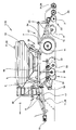
Die Figur zeigt eine Bestellkombination 1, die als gezogene Bestellkombination 13 ausgebildet ist. Die gezogene Bestellkombination 13 wird über die Zugeinrichtung 16 mit dem Dreipunktgestänge, dem Zugpendel oder der Anhängerkupplung eines nicht dargestellten Zugfahrzeuges bzw. Traktors verbunden. Die Zugeinrichtung 16 ist Bestandteil der Deichsel 17, die mit dem Grundrahmen 18 verbunden ist. Auf dem Grundrahmen 18 befindet sich der Saatgutbehälter 19. Zwischen Grundrahmen 18 und Saatgutbehälter 19 ist die Regeleinrichtung 6 untergebracht, die vorzugsweise mit einem nicht dargestellten Bedienterminal in Verbindung steht, das während des Betriebes in der Traktorkabine untergebracht ist. Über das Bedienterminal werden alle Funktionen der Bestellkombination 1 überwacht und auch alle notwendigen Einstellungen vorgenommen. Unterhalb des Grundrahmens 18 befinden sich die Bodenbearbeitungswerkzeuge 2, die dem Rahmen 8 zugeordnet sind, der über die Hydraulikzylinder 9 zusammen mit den Bodenbearbeitungswerkzeugen 2 in der Höhe einstellbar ist. Als Bodenbearbeitungswerkzeuge 2 sind hier Hohlscheiben 31 vorgesehen. Die links und rechts außen am Rahmen 8 der Bodenbearbeitungswerkzeuge 2 angeordneten Begrenzungsscheiben 32 unterstützen die Arbeitseffekte der Hohlscheiben 31. Vorne am Rahmen 8 der Bodenbearbeitungswerkzeuge 2 befinden sich die Planierwerkzeuge 30, die in Relation zu den Bodenbearbeitungswerkzeugen 2 über den Hydraulikzylinder 33 in der Arbeitsstellung einstellbar sind. Hinten am Grundrahmen 18 befindet sich der Tragrahmen 20, der über eine Hubvorrichtung 21 die Walze 4, die Säschiene 22 mit den Säscharen 3 und die den Säscharen 3 zugeordneten Druckrollen 23 und auch das Impulsrad 24 trägt. Die Walze 4 weist die Vorrichtung 10 auf, über die die Umdrehungsgeschwindigkeit der Walze 4 ermittelt wird. Das Impulsrad 24 weist eine zusätzliche Vorrichtung 11 auf, die die Arbeitsgeschwindigkeit der Bestellkombination 1 ermittelt. Es kann auch ein GPS-Empfänger 25 oder ein Radar-Sensor 26 als zusätzliche Vorrichtung 11 zur Ermittlung der tatsächlichen Arbeitsgeschwindigkeit der Bestellkombination 1 genutzt werden. Der Grundrahmen 18 stützt sich auf das Fahrwerk 7 ab, das sich in Fahrtrichtung 5 gesehen hinter den Bodenbearbeitungswerkzeugen 2 befindet. In Fahrtrichtung 5 gesehen ist die Walze 4 hinter dem Fahrwerk 7 angeordnet und vor der Säschiene 22 mit den Säscharen 3. Die zusätzliche Vorrichtung 11 für die Ermittlung der tatsächlichen Arbeitsgeschwindigkeit der Bestellkombination 1 kann auch dem Fahrwerk 7 zugeordnet werden, was in Verbindung mit der Vorrichtung 10 für die Ermittlung der Umdrehungsgeschwindigkeit der Walze 4 eine einfache Lösung darstellt. Die Vorrichtung 10 und die zusätzliche Vorrichtung 11 können aus einfachen Sensoren bestehen, die über Impulsgeber die Signale erzeugen, die dann von der Regeleinrichtung 6 ausgewertet werden und so die Druckbelastung auf die Walze 4 vorgeben. Für die Ausübung der Druckbelastung auf die Walze 4 dient der Hydraulikzylinder 34. Der Hydraulikzylinder 35 dient zur Einstellung des Schardruckes der Säschare 3.The figure shows an order combination 1, which is designed as a drawn order combination 13. The drawn order combination 13 is connected via the
Claims (5)
dadurch gekennzeichnet,
dass eine Vorrichtung (10) vorgesehen ist für die Ermittlung der Umdrehungsgeschwindigkeit der Walze (4) und eine zusätzliche Vorrichtung (11) für die Ermittlung der tatsächlichen Arbeitsgeschwindigkeit der Bestellkombination (1) und dass bei Überschreitung eines vorgegebenen Schlupfgrenzwertes zwischen der Umdrehungsgeschwindigkeit der Walze (4) und der Arbeitsgeschwindigkeit der Bestellkombination (1) die Druckbelastung auf die Walze (4) über die Regeleinrichtung (6) derart verändert wird, dass ein vorgegebener Schlupfgrenzwert der Walze (4) nicht überschritten wird,Ordering combination (1) with tillage tools (2), coulters (3) and a roller (4) which is arranged in the working direction (5) behind the tillage tools (2) and before the coulters (3) and with a control device (6), the pressure load of the roller (4) is designed to regulate the floor, the order combination (1) being carried by a chassis (7),
characterized,
in that a device (10) is provided for determining the rotational speed of the roller (4) and an additional device (11) for determining the actual working speed of the order combination (1) and that when the predetermined speed limit value is exceeded between the rotational speed of the roller (4 ) and the working speed of the order combination (1) the pressure load on the roller (4) via the control device (6) is changed such that a predetermined slip limit of the roller (4) is not exceeded,
dadurch gekennzeichnet,
dass die Regeleinrichtung (6) über elektrische, pneumatische oder hydraulische Stellsysteme die Druckbelastung auf die Walze (4) regelnd ausgebildet ist.Ordering combination according to claim 1,
characterized,
that the control device (6) via electrical, pneumatic or hydraulic actuation systems, the pressure load on the roller (4) is regulating.
dadurch gekennzeichnet,
dass die zusätzliche Vorrichtung (11) für die Erfassung der Arbeitsgeschwindigkeit der Bestellkombination (1) dem Traktor oder der Bestellkombination (1) zugeordnet ist.Ordering combination according to claim 1,
characterized,
in that the additional device (11) for detecting the working speed of the order combination (1) is associated with the tractor or the order combination (1).
dadurch gekennzeichnet.
dass bei mehrteiligen Walzen (4) mindestens einer Walze (4) eine Vorrichtung (10) für die Ermittlung der Umdrehungsgeschwindigkeit der Walze (4) zugeordnet ist.Ordering combination according to claim 1,
characterized.
that in multi-piece rollers (4) at least one roller (4) is associated with a device (10) for determining the rotational speed of the roller (4).
dadurch gekennzeichnet,
dass bei Druckentlastung der Walze (4) das entlastete Gewicht auf das Fahrwerk (7) verlagert wird, wobei das Fahrwerk (7) dem Traktor oder der Bestellkombination (1) zugeordnet ist.Ordering combination according to claim 1,
characterized,
that when pressure relief of the roller (4), the weight relieved on the chassis (7) is displaced, wherein the chassis (7) is associated with the tractor or the order combination (1).
Priority Applications (2)
| Application Number | Priority Date | Filing Date | Title |
|---|---|---|---|
| PL11001564T PL2363013T3 (en) | 2010-03-02 | 2011-02-25 | Cultivating and sowing combination with device for complying with a slip threshold |
| SI201130029T SI2363013T1 (en) | 2010-03-02 | 2011-02-25 | Cultivating and sowing combination with device for complying with a slip threshold |
Applications Claiming Priority (1)
| Application Number | Priority Date | Filing Date | Title |
|---|---|---|---|
| DE102010009819A DE102010009819A1 (en) | 2010-03-02 | 2010-03-02 | Bestellkombination |
Publications (2)
| Publication Number | Publication Date |
|---|---|
| EP2363013A1 true EP2363013A1 (en) | 2011-09-07 |
| EP2363013B1 EP2363013B1 (en) | 2013-04-17 |
Family
ID=44063895
Family Applications (1)
| Application Number | Title | Priority Date | Filing Date |
|---|---|---|---|
| EP11001564.1A Active EP2363013B1 (en) | 2010-03-02 | 2011-02-25 | Cultivating and sowing combination with device for complying with a slip threshold |
Country Status (8)
| Country | Link |
|---|---|
| EP (1) | EP2363013B1 (en) |
| DE (1) | DE102010009819A1 (en) |
| DK (1) | DK2363013T3 (en) |
| ES (1) | ES2408880T3 (en) |
| PL (1) | PL2363013T3 (en) |
| PT (1) | PT2363013E (en) |
| RS (1) | RS52791B (en) |
| SI (1) | SI2363013T1 (en) |
Cited By (2)
| Publication number | Priority date | Publication date | Assignee | Title |
|---|---|---|---|---|
| EP2556735A1 (en) * | 2011-08-11 | 2013-02-13 | Lemken GmbH & Co. KG | Soil cultivation device with device for maintaining a slippage threshold at constant working depth |
| CN103718684A (en) * | 2014-01-02 | 2014-04-16 | 张春平 | Machine capable of carrying out rotary tillage, four-plough ridge combination, seeding, chemical weeding and film lamination |
Families Citing this family (1)
| Publication number | Priority date | Publication date | Assignee | Title |
|---|---|---|---|---|
| DE102021133440A1 (en) | 2021-12-16 | 2023-06-22 | Lemken Gmbh & Co. Kg | Running gear with braking device |
Citations (9)
| Publication number | Priority date | Publication date | Assignee | Title |
|---|---|---|---|---|
| EP0632953A2 (en) * | 1993-06-29 | 1995-01-11 | Franz Kleine Maschinenfabrik GmbH & Co. | Soil working machine |
| DE19633119A1 (en) * | 1996-08-16 | 1998-02-19 | Amazonen Werke Dreyer H | Land cultivator for agricultural applications |
| EP1273215A1 (en) * | 2001-07-07 | 2003-01-08 | Deere & Company | Agricultural machinery combination |
| EP1336330A1 (en) * | 2002-02-14 | 2003-08-20 | Kuhn-Huard S.A. | Sowing machine |
| WO2003086842A1 (en) * | 2002-04-18 | 2003-10-23 | Herbert Fettweis | Baler and method for improving power utilisation and/or power improvement of a tractor unit |
| EP1825733A1 (en) * | 2006-02-22 | 2007-08-29 | Amazonen-Werke H. Dreyer GmbH & Co. KG | Soil cultivation device |
| US20080257570A1 (en) * | 2007-04-17 | 2008-10-23 | Johnny Keplinger | Electronic draft control for semi-trailed implements |
| EP2016816A2 (en) | 2007-06-05 | 2009-01-21 | Lemken GmbH & Co. KG | Collapsible cultivating and sowing combination |
| WO2009071253A1 (en) * | 2007-12-08 | 2009-06-11 | Agco Sa | Implement control systems |
Family Cites Families (1)
| Publication number | Priority date | Publication date | Assignee | Title |
|---|---|---|---|---|
| DE3513064A1 (en) * | 1985-04-12 | 1986-10-23 | Xaver Fendt & Co, 8952 Marktoberdorf | Control method and control device working accordingly for traction vehicles which can be used for agricultural purposes |
-
2010
- 2010-03-02 DE DE102010009819A patent/DE102010009819A1/en not_active Withdrawn
-
2011
- 2011-02-25 DK DK11001564.1T patent/DK2363013T3/en active
- 2011-02-25 PL PL11001564T patent/PL2363013T3/en unknown
- 2011-02-25 EP EP11001564.1A patent/EP2363013B1/en active Active
- 2011-02-25 ES ES11001564T patent/ES2408880T3/en active Active
- 2011-02-25 RS RS20130215A patent/RS52791B/en unknown
- 2011-02-25 PT PT110015641T patent/PT2363013E/en unknown
- 2011-02-25 SI SI201130029T patent/SI2363013T1/en unknown
Patent Citations (9)
| Publication number | Priority date | Publication date | Assignee | Title |
|---|---|---|---|---|
| EP0632953A2 (en) * | 1993-06-29 | 1995-01-11 | Franz Kleine Maschinenfabrik GmbH & Co. | Soil working machine |
| DE19633119A1 (en) * | 1996-08-16 | 1998-02-19 | Amazonen Werke Dreyer H | Land cultivator for agricultural applications |
| EP1273215A1 (en) * | 2001-07-07 | 2003-01-08 | Deere & Company | Agricultural machinery combination |
| EP1336330A1 (en) * | 2002-02-14 | 2003-08-20 | Kuhn-Huard S.A. | Sowing machine |
| WO2003086842A1 (en) * | 2002-04-18 | 2003-10-23 | Herbert Fettweis | Baler and method for improving power utilisation and/or power improvement of a tractor unit |
| EP1825733A1 (en) * | 2006-02-22 | 2007-08-29 | Amazonen-Werke H. Dreyer GmbH & Co. KG | Soil cultivation device |
| US20080257570A1 (en) * | 2007-04-17 | 2008-10-23 | Johnny Keplinger | Electronic draft control for semi-trailed implements |
| EP2016816A2 (en) | 2007-06-05 | 2009-01-21 | Lemken GmbH & Co. KG | Collapsible cultivating and sowing combination |
| WO2009071253A1 (en) * | 2007-12-08 | 2009-06-11 | Agco Sa | Implement control systems |
Cited By (2)
| Publication number | Priority date | Publication date | Assignee | Title |
|---|---|---|---|---|
| EP2556735A1 (en) * | 2011-08-11 | 2013-02-13 | Lemken GmbH & Co. KG | Soil cultivation device with device for maintaining a slippage threshold at constant working depth |
| CN103718684A (en) * | 2014-01-02 | 2014-04-16 | 张春平 | Machine capable of carrying out rotary tillage, four-plough ridge combination, seeding, chemical weeding and film lamination |
Also Published As
| Publication number | Publication date |
|---|---|
| PL2363013T3 (en) | 2013-09-30 |
| DE102010009819A1 (en) | 2011-09-08 |
| ES2408880T3 (en) | 2013-06-21 |
| DK2363013T3 (en) | 2013-06-17 |
| SI2363013T1 (en) | 2013-07-31 |
| RS52791B (en) | 2013-10-31 |
| EP2363013B1 (en) | 2013-04-17 |
| PT2363013E (en) | 2013-05-23 |
Similar Documents
| Publication | Publication Date | Title |
|---|---|---|
| EP3026997B1 (en) | Soil cultivation implement having a device for reconsolidation | |
| EP2462794B1 (en) | Agricultural machine | |
| DE102011085040A1 (en) | Agricultural vehicle | |
| WO2016192973A1 (en) | Control arrangement for a traction engine, traction engine having a control arrangement and method for a control arrangement | |
| DE102018221425A1 (en) | Object recognition and documentation system for tillage equipment | |
| EP2556735B1 (en) | Soil cultivation device with device for maintaining a slippage threshold at constant working depth | |
| EP3311641A1 (en) | Control device for a tractor, tractor provided with a control device and method of controlling a tractor | |
| EP2363013B1 (en) | Cultivating and sowing combination with device for complying with a slip threshold | |
| EP3424287B1 (en) | Device and method for controlling the operation of a hydraulically actuated towing device on a vehicle | |
| EP3300557B1 (en) | Device and method for controlling the operation of a hydraulically actuated towing device on a vehicle | |
| DE102015119145A1 (en) | Control and / or control system for an agricultural machine | |
| EP0928553B1 (en) | Agricultural applying combine | |
| EP3424788B1 (en) | Agricultural work vehicle | |
| DE10039600B4 (en) | Multi-share rotary plow | |
| DE102017129243A1 (en) | System for dynamic tire pressure monitoring of a farm vehicle | |
| EP1825733B1 (en) | Soil cultivation device | |
| DE102010017753A1 (en) | Agricultural device, has switch device including sensor for detecting raised position or lowered position of distributor, so as to determine distance of distributor to soil surface, where sensor is formed as non-contact probe | |
| DE102016119883A1 (en) | Agricultural machine | |
| DE102019115301B4 (en) | Control and/or regulating device and method for operating an attachment on a vehicle | |
| DE102017103646A1 (en) | Agricultural machine and process for an agricultural machine | |
| EP3569458B1 (en) | Agricultural train, brake system for an agricultural train and method for operating a brake system of an agricultural train | |
| AT524930B1 (en) | Method of sowing using a seeder | |
| EP3299232B1 (en) | Agricultural spreader machine with brake force-regulating system and method for regulating brake power | |
| DE102007026468B3 (en) | Foldable order combination | |
| EP3771320B1 (en) | Method for adjusting the inclination of an agricultural spreader |
Legal Events
| Date | Code | Title | Description |
|---|---|---|---|
| PUAI | Public reference made under article 153(3) epc to a published international application that has entered the european phase |
Free format text: ORIGINAL CODE: 0009012 |
|
| AK | Designated contracting states |
Kind code of ref document: A1 Designated state(s): AL AT BE BG CH CY CZ DE DK EE ES FI FR GB GR HR HU IE IS IT LI LT LU LV MC MK MT NL NO PL PT RO RS SE SI SK SM TR |
|
| AX | Request for extension of the european patent |
Extension state: BA ME |
|
| 17P | Request for examination filed |
Effective date: 20120307 |
|
| GRAP | Despatch of communication of intention to grant a patent |
Free format text: ORIGINAL CODE: EPIDOSNIGR1 |
|
| GRAS | Grant fee paid |
Free format text: ORIGINAL CODE: EPIDOSNIGR3 |
|
| GRAA | (expected) grant |
Free format text: ORIGINAL CODE: 0009210 |
|
| AK | Designated contracting states |
Kind code of ref document: B1 Designated state(s): AL AT BE BG CH CY CZ DE DK EE ES FI FR GB GR HR HU IE IS IT LI LT LU LV MC MK MT NL NO PL PT RO RS SE SI SK SM TR |
|
| REG | Reference to a national code |
Ref country code: GB Ref legal event code: FG4D Free format text: NOT ENGLISH |
|
| REG | Reference to a national code |
Ref country code: CH Ref legal event code: EP |
|
| REG | Reference to a national code |
Ref country code: IE Ref legal event code: FG4D Free format text: LANGUAGE OF EP DOCUMENT: GERMAN |
|
| REG | Reference to a national code |
Ref country code: RO Ref legal event code: EPE |
|
| REG | Reference to a national code |
Ref country code: CH Ref legal event code: NV Representative=s name: ALDO ROEMPLER PATENTANWALT, CH Ref country code: AT Ref legal event code: REF Ref document number: 606627 Country of ref document: AT Kind code of ref document: T Effective date: 20130515 |
|
| REG | Reference to a national code |
Ref country code: PT Ref legal event code: SC4A Free format text: AVAILABILITY OF NATIONAL TRANSLATION Effective date: 20130516 |
|
| REG | Reference to a national code |
Ref country code: DE Ref legal event code: R096 Ref document number: 502011000606 Country of ref document: DE Effective date: 20130613 |
|
| REG | Reference to a national code |
Ref country code: DK Ref legal event code: T3 |
|
| REG | Reference to a national code |
Ref country code: SE Ref legal event code: TRGR |
|
| REG | Reference to a national code |
Ref country code: ES Ref legal event code: FG2A Ref document number: 2408880 Country of ref document: ES Kind code of ref document: T3 Effective date: 20130621 |
|
| REG | Reference to a national code |
Ref country code: NL Ref legal event code: T3 |
|
| REG | Reference to a national code |
Ref country code: SK Ref legal event code: T3 Ref document number: E 14094 Country of ref document: SK |
|
| REG | Reference to a national code |
Ref country code: NO Ref legal event code: T2 Effective date: 20130417 |
|
| REG | Reference to a national code |
Ref country code: PL Ref legal event code: T3 |
|
| REG | Reference to a national code |
Ref country code: EE Ref legal event code: FG4A Ref document number: E008120 Country of ref document: EE Effective date: 20130703 |
|
| PG25 | Lapsed in a contracting state [announced via postgrant information from national office to epo] |
Ref country code: GR Free format text: LAPSE BECAUSE OF FAILURE TO SUBMIT A TRANSLATION OF THE DESCRIPTION OR TO PAY THE FEE WITHIN THE PRESCRIBED TIME-LIMIT Effective date: 20130718 Ref country code: IS Free format text: LAPSE BECAUSE OF FAILURE TO SUBMIT A TRANSLATION OF THE DESCRIPTION OR TO PAY THE FEE WITHIN THE PRESCRIBED TIME-LIMIT Effective date: 20130817 |
|
| PG25 | Lapsed in a contracting state [announced via postgrant information from national office to epo] |
Ref country code: CY Free format text: LAPSE BECAUSE OF FAILURE TO SUBMIT A TRANSLATION OF THE DESCRIPTION OR TO PAY THE FEE WITHIN THE PRESCRIBED TIME-LIMIT Effective date: 20130417 Ref country code: HR Free format text: LAPSE BECAUSE OF FAILURE TO SUBMIT A TRANSLATION OF THE DESCRIPTION OR TO PAY THE FEE WITHIN THE PRESCRIBED TIME-LIMIT Effective date: 20130417 |
|
| PLBE | No opposition filed within time limit |
Free format text: ORIGINAL CODE: 0009261 |
|
| STAA | Information on the status of an ep patent application or granted ep patent |
Free format text: STATUS: NO OPPOSITION FILED WITHIN TIME LIMIT |
|
| 26N | No opposition filed |
Effective date: 20140120 |
|
| REG | Reference to a national code |
Ref country code: HU Ref legal event code: AG4A Ref document number: E018639 Country of ref document: HU |
|
| REG | Reference to a national code |
Ref country code: DE Ref legal event code: R097 Ref document number: 502011000606 Country of ref document: DE Effective date: 20140120 |
|
| PG25 | Lapsed in a contracting state [announced via postgrant information from national office to epo] |
Ref country code: MC Free format text: LAPSE BECAUSE OF FAILURE TO SUBMIT A TRANSLATION OF THE DESCRIPTION OR TO PAY THE FEE WITHIN THE PRESCRIBED TIME-LIMIT Effective date: 20130417 |
|
| REG | Reference to a national code |
Ref country code: IE Ref legal event code: MM4A |
|
| PG25 | Lapsed in a contracting state [announced via postgrant information from national office to epo] |
Ref country code: IE Free format text: LAPSE BECAUSE OF NON-PAYMENT OF DUE FEES Effective date: 20140225 |
|
| PG25 | Lapsed in a contracting state [announced via postgrant information from national office to epo] |
Ref country code: MT Free format text: LAPSE BECAUSE OF FAILURE TO SUBMIT A TRANSLATION OF THE DESCRIPTION OR TO PAY THE FEE WITHIN THE PRESCRIBED TIME-LIMIT Effective date: 20130417 |
|
| REG | Reference to a national code |
Ref country code: FR Ref legal event code: PLFP Year of fee payment: 6 |
|
| PG25 | Lapsed in a contracting state [announced via postgrant information from national office to epo] |
Ref country code: SM Free format text: LAPSE BECAUSE OF FAILURE TO SUBMIT A TRANSLATION OF THE DESCRIPTION OR TO PAY THE FEE WITHIN THE PRESCRIBED TIME-LIMIT Effective date: 20130417 |
|
| PG25 | Lapsed in a contracting state [announced via postgrant information from national office to epo] |
Ref country code: TR Free format text: LAPSE BECAUSE OF FAILURE TO SUBMIT A TRANSLATION OF THE DESCRIPTION OR TO PAY THE FEE WITHIN THE PRESCRIBED TIME-LIMIT Effective date: 20130417 |
|
| REG | Reference to a national code |
Ref country code: FR Ref legal event code: PLFP Year of fee payment: 7 |
|
| REG | Reference to a national code |
Ref country code: FR Ref legal event code: PLFP Year of fee payment: 8 |
|
| PG25 | Lapsed in a contracting state [announced via postgrant information from national office to epo] |
Ref country code: MK Free format text: LAPSE BECAUSE OF FAILURE TO SUBMIT A TRANSLATION OF THE DESCRIPTION OR TO PAY THE FEE WITHIN THE PRESCRIBED TIME-LIMIT Effective date: 20130417 |
|
| PG25 | Lapsed in a contracting state [announced via postgrant information from national office to epo] |
Ref country code: AL Free format text: LAPSE BECAUSE OF FAILURE TO SUBMIT A TRANSLATION OF THE DESCRIPTION OR TO PAY THE FEE WITHIN THE PRESCRIBED TIME-LIMIT Effective date: 20130417 |
|
| PGFP | Annual fee paid to national office [announced via postgrant information from national office to epo] |
Ref country code: NL Payment date: 20190225 Year of fee payment: 9 Ref country code: LU Payment date: 20190226 Year of fee payment: 9 |
|
| PGFP | Annual fee paid to national office [announced via postgrant information from national office to epo] |
Ref country code: ES Payment date: 20190319 Year of fee payment: 16 Ref country code: FI Payment date: 20190219 Year of fee payment: 9 Ref country code: PL Payment date: 20190213 Year of fee payment: 9 Ref country code: BG Payment date: 20190219 Year of fee payment: 9 Ref country code: GB Payment date: 20190227 Year of fee payment: 9 Ref country code: NO Payment date: 20190221 Year of fee payment: 9 Ref country code: IT Payment date: 20190221 Year of fee payment: 9 Ref country code: CH Payment date: 20190225 Year of fee payment: 9 Ref country code: LT Payment date: 20190225 Year of fee payment: 9 Ref country code: CZ Payment date: 20190222 Year of fee payment: 9 |
|
| PGFP | Annual fee paid to national office [announced via postgrant information from national office to epo] |
Ref country code: SI Payment date: 20190211 Year of fee payment: 9 Ref country code: RS Payment date: 20190211 Year of fee payment: 9 Ref country code: LV Payment date: 20190301 Year of fee payment: 9 Ref country code: SE Payment date: 20190222 Year of fee payment: 9 Ref country code: DK Payment date: 20190225 Year of fee payment: 9 Ref country code: BE Payment date: 20190225 Year of fee payment: 9 |
|
| PGFP | Annual fee paid to national office [announced via postgrant information from national office to epo] |
Ref country code: SK Payment date: 20190221 Year of fee payment: 9 |
|
| PGFP | Annual fee paid to national office [announced via postgrant information from national office to epo] |
Ref country code: PT Payment date: 20190220 Year of fee payment: 9 |
|
| REG | Reference to a national code |
Ref country code: DE Ref legal event code: R082 Ref document number: 502011000606 Country of ref document: DE |
|
| REG | Reference to a national code |
Ref country code: EE Ref legal event code: MM4A Ref document number: E008120 Country of ref document: EE Effective date: 20200228 |
|
| REG | Reference to a national code |
Ref country code: FI Ref legal event code: MAE |
|
| REG | Reference to a national code |
Ref country code: DK Ref legal event code: EBP Effective date: 20200229 |
|
| REG | Reference to a national code |
Ref country code: NO Ref legal event code: MMEP |
|
| REG | Reference to a national code |
Ref country code: SE Ref legal event code: EUG |
|
| REG | Reference to a national code |
Ref country code: CH Ref legal event code: PL |
|
| REG | Reference to a national code |
Ref country code: NL Ref legal event code: MM Effective date: 20200301 |
|
| GBPC | Gb: european patent ceased through non-payment of renewal fee |
Effective date: 20200225 |
|
| REG | Reference to a national code |
Ref country code: BE Ref legal event code: MM Effective date: 20200229 |
|
| PG25 | Lapsed in a contracting state [announced via postgrant information from national office to epo] |
Ref country code: CZ Free format text: LAPSE BECAUSE OF NON-PAYMENT OF DUE FEES Effective date: 20200225 Ref country code: LU Free format text: LAPSE BECAUSE OF NON-PAYMENT OF DUE FEES Effective date: 20200225 Ref country code: SK Free format text: LAPSE BECAUSE OF NON-PAYMENT OF DUE FEES Effective date: 20200225 Ref country code: RO Free format text: LAPSE BECAUSE OF NON-PAYMENT OF DUE FEES Effective date: 20200225 Ref country code: FI Free format text: LAPSE BECAUSE OF NON-PAYMENT OF DUE FEES Effective date: 20200225 Ref country code: NO Free format text: LAPSE BECAUSE OF NON-PAYMENT OF DUE FEES Effective date: 20200229 Ref country code: EE Free format text: LAPSE BECAUSE OF NON-PAYMENT OF DUE FEES Effective date: 20200229 Ref country code: SE Free format text: LAPSE BECAUSE OF NON-PAYMENT OF DUE FEES Effective date: 20200226 Ref country code: PT Free format text: LAPSE BECAUSE OF NON-PAYMENT OF DUE FEES Effective date: 20200925 |
|
| REG | Reference to a national code |
Ref country code: SK Ref legal event code: MM4A Ref document number: E 14094 Country of ref document: SK Effective date: 20200225 |
|
| REG | Reference to a national code |
Ref country code: LT Ref legal event code: MM4D Effective date: 20200225 |
|
| PG25 | Lapsed in a contracting state [announced via postgrant information from national office to epo] |
Ref country code: LV Free format text: LAPSE BECAUSE OF NON-PAYMENT OF DUE FEES Effective date: 20200225 Ref country code: LI Free format text: LAPSE BECAUSE OF NON-PAYMENT OF DUE FEES Effective date: 20200229 Ref country code: BG Free format text: LAPSE BECAUSE OF NON-PAYMENT OF DUE FEES Effective date: 20200831 Ref country code: CH Free format text: LAPSE BECAUSE OF NON-PAYMENT OF DUE FEES Effective date: 20200229 Ref country code: RS Free format text: LAPSE BECAUSE OF NON-PAYMENT OF DUE FEES Effective date: 20200225 Ref country code: SI Free format text: LAPSE BECAUSE OF NON-PAYMENT OF DUE FEES Effective date: 20200226 Ref country code: HU Free format text: LAPSE BECAUSE OF NON-PAYMENT OF DUE FEES Effective date: 20200226 |
|
| PG25 | Lapsed in a contracting state [announced via postgrant information from national office to epo] |
Ref country code: NL Free format text: LAPSE BECAUSE OF NON-PAYMENT OF DUE FEES Effective date: 20200301 |
|
| PG25 | Lapsed in a contracting state [announced via postgrant information from national office to epo] |
Ref country code: LT Free format text: LAPSE BECAUSE OF NON-PAYMENT OF DUE FEES Effective date: 20200225 Ref country code: GB Free format text: LAPSE BECAUSE OF NON-PAYMENT OF DUE FEES Effective date: 20200225 Ref country code: DK Free format text: LAPSE BECAUSE OF NON-PAYMENT OF DUE FEES Effective date: 20200229 |
|
| PG25 | Lapsed in a contracting state [announced via postgrant information from national office to epo] |
Ref country code: BE Free format text: LAPSE BECAUSE OF NON-PAYMENT OF DUE FEES Effective date: 20200229 |
|
| REG | Reference to a national code |
Ref country code: ES Ref legal event code: FD2A Effective date: 20210708 |
|
| PG25 | Lapsed in a contracting state [announced via postgrant information from national office to epo] |
Ref country code: IT Free format text: LAPSE BECAUSE OF NON-PAYMENT OF DUE FEES Effective date: 20200225 |
|
| PG25 | Lapsed in a contracting state [announced via postgrant information from national office to epo] |
Ref country code: ES Free format text: LAPSE BECAUSE OF NON-PAYMENT OF DUE FEES Effective date: 20200226 |
|
| PG25 | Lapsed in a contracting state [announced via postgrant information from national office to epo] |
Ref country code: PL Free format text: LAPSE BECAUSE OF NON-PAYMENT OF DUE FEES Effective date: 20200225 |
|
| PGFP | Annual fee paid to national office [announced via postgrant information from national office to epo] |
Ref country code: FR Payment date: 20230223 Year of fee payment: 13 Ref country code: AT Payment date: 20230215 Year of fee payment: 13 |
|
| PGFP | Annual fee paid to national office [announced via postgrant information from national office to epo] |
Ref country code: DE Payment date: 20230203 Year of fee payment: 13 |
|
| P01 | Opt-out of the competence of the unified patent court (upc) registered |
Effective date: 20230518 |