EP2362933B1 - Counter flow indirect evaporative heat exchanger - Google Patents
Counter flow indirect evaporative heat exchanger Download PDFInfo
- Publication number
- EP2362933B1 EP2362933B1 EP09825644.9A EP09825644A EP2362933B1 EP 2362933 B1 EP2362933 B1 EP 2362933B1 EP 09825644 A EP09825644 A EP 09825644A EP 2362933 B1 EP2362933 B1 EP 2362933B1
- Authority
- EP
- European Patent Office
- Prior art keywords
- heat exchanger
- water
- wet
- passages
- dry
- Prior art date
- Legal status (The legal status is an assumption and is not a legal conclusion. Google has not performed a legal analysis and makes no representation as to the accuracy of the status listed.)
- Active
Links
- XLYOFNOQVPJJNP-UHFFFAOYSA-N water Substances O XLYOFNOQVPJJNP-UHFFFAOYSA-N 0.000 claims description 83
- 238000009736 wetting Methods 0.000 claims description 24
- 238000000034 method Methods 0.000 claims description 8
- 230000002745 absorbent Effects 0.000 claims description 6
- 239000002250 absorbent Substances 0.000 claims description 6
- 239000012528 membrane Substances 0.000 claims description 4
- 229920002678 cellulose Polymers 0.000 claims description 2
- 239000001913 cellulose Substances 0.000 claims description 2
- 230000000295 complement effect Effects 0.000 claims description 2
- 230000001419 dependent effect Effects 0.000 claims 2
- 238000001035 drying Methods 0.000 claims 1
- 238000001816 cooling Methods 0.000 description 15
- 238000010276 construction Methods 0.000 description 7
- 238000001704 evaporation Methods 0.000 description 7
- 230000008020 evaporation Effects 0.000 description 6
- 230000001010 compromised effect Effects 0.000 description 4
- 238000011010 flushing procedure Methods 0.000 description 4
- 150000003839 salts Chemical class 0.000 description 4
- 239000000463 material Substances 0.000 description 3
- 230000003068 static effect Effects 0.000 description 3
- 230000015556 catabolic process Effects 0.000 description 2
- 239000000356 contaminant Substances 0.000 description 2
- 238000006731 degradation reaction Methods 0.000 description 2
- 230000000694 effects Effects 0.000 description 2
- 239000007921 spray Substances 0.000 description 2
- 238000009825 accumulation Methods 0.000 description 1
- 238000004378 air conditioning Methods 0.000 description 1
- 230000001668 ameliorated effect Effects 0.000 description 1
- 230000009286 beneficial effect Effects 0.000 description 1
- 230000001143 conditioned effect Effects 0.000 description 1
- 230000003750 conditioning effect Effects 0.000 description 1
- 230000007423 decrease Effects 0.000 description 1
- 230000002349 favourable effect Effects 0.000 description 1
- 238000010348 incorporation Methods 0.000 description 1
- 230000002262 irrigation Effects 0.000 description 1
- 238000003973 irrigation Methods 0.000 description 1
- 238000004519 manufacturing process Methods 0.000 description 1
- 229910052751 metal Inorganic materials 0.000 description 1
- 239000002184 metal Substances 0.000 description 1
- 150000002739 metals Chemical class 0.000 description 1
- 239000000203 mixture Substances 0.000 description 1
- 230000000737 periodic effect Effects 0.000 description 1
Images


Classifications
-
- F—MECHANICAL ENGINEERING; LIGHTING; HEATING; WEAPONS; BLASTING
- F28—HEAT EXCHANGE IN GENERAL
- F28D—HEAT-EXCHANGE APPARATUS, NOT PROVIDED FOR IN ANOTHER SUBCLASS, IN WHICH THE HEAT-EXCHANGE MEDIA DO NOT COME INTO DIRECT CONTACT
- F28D5/00—Heat-exchange apparatus having stationary conduit assemblies for one heat-exchange medium only, the media being in contact with different sides of the conduit wall, using the cooling effect of natural or forced evaporation
- F28D5/02—Heat-exchange apparatus having stationary conduit assemblies for one heat-exchange medium only, the media being in contact with different sides of the conduit wall, using the cooling effect of natural or forced evaporation in which the evaporating medium flows in a continuous film or trickles freely over the conduits
-
- F—MECHANICAL ENGINEERING; LIGHTING; HEATING; WEAPONS; BLASTING
- F24—HEATING; RANGES; VENTILATING
- F24F—AIR-CONDITIONING; AIR-HUMIDIFICATION; VENTILATION; USE OF AIR CURRENTS FOR SCREENING
- F24F1/00—Room units for air-conditioning, e.g. separate or self-contained units or units receiving primary air from a central station
- F24F1/0007—Indoor units, e.g. fan coil units
- F24F1/0059—Indoor units, e.g. fan coil units characterised by heat exchangers
- F24F1/0063—Indoor units, e.g. fan coil units characterised by heat exchangers by the mounting or arrangement of the heat exchangers
-
- F—MECHANICAL ENGINEERING; LIGHTING; HEATING; WEAPONS; BLASTING
- F24—HEATING; RANGES; VENTILATING
- F24F—AIR-CONDITIONING; AIR-HUMIDIFICATION; VENTILATION; USE OF AIR CURRENTS FOR SCREENING
- F24F5/00—Air-conditioning systems or apparatus not covered by F24F1/00 or F24F3/00, e.g. using solar heat or combined with household units such as an oven or water heater
- F24F5/0007—Air-conditioning systems or apparatus not covered by F24F1/00 or F24F3/00, e.g. using solar heat or combined with household units such as an oven or water heater cooling apparatus specially adapted for use in air-conditioning
- F24F5/0035—Air-conditioning systems or apparatus not covered by F24F1/00 or F24F3/00, e.g. using solar heat or combined with household units such as an oven or water heater cooling apparatus specially adapted for use in air-conditioning using evaporation
-
- F—MECHANICAL ENGINEERING; LIGHTING; HEATING; WEAPONS; BLASTING
- F24—HEATING; RANGES; VENTILATING
- F24F—AIR-CONDITIONING; AIR-HUMIDIFICATION; VENTILATION; USE OF AIR CURRENTS FOR SCREENING
- F24F6/00—Air-humidification, e.g. cooling by humidification
- F24F6/02—Air-humidification, e.g. cooling by humidification by evaporation of water in the air
- F24F6/04—Air-humidification, e.g. cooling by humidification by evaporation of water in the air using stationary unheated wet elements
- F24F6/043—Air-humidification, e.g. cooling by humidification by evaporation of water in the air using stationary unheated wet elements with self-sucking action, e.g. wicks
-
- Y—GENERAL TAGGING OF NEW TECHNOLOGICAL DEVELOPMENTS; GENERAL TAGGING OF CROSS-SECTIONAL TECHNOLOGIES SPANNING OVER SEVERAL SECTIONS OF THE IPC; TECHNICAL SUBJECTS COVERED BY FORMER USPC CROSS-REFERENCE ART COLLECTIONS [XRACs] AND DIGESTS
- Y02—TECHNOLOGIES OR APPLICATIONS FOR MITIGATION OR ADAPTATION AGAINST CLIMATE CHANGE
- Y02B—CLIMATE CHANGE MITIGATION TECHNOLOGIES RELATED TO BUILDINGS, e.g. HOUSING, HOUSE APPLIANCES OR RELATED END-USER APPLICATIONS
- Y02B30/00—Energy efficient heating, ventilation or air conditioning [HVAC]
- Y02B30/54—Free-cooling systems
Definitions
- the present invention relates to counter flow indirect evaporative heat exchangers for evaporative coolers; for example, self contained air-conditioning units suitable for supplying cooled air to an enclosed space and also to self contained conditioning units suitable for supplying cooled water for use in heat exchange units forming part of a system for the cooling of enclosed spaces.
- coolers Of great practical importance in the provision of coolers is their size and shape which must be such as to fit and blend into the surroundings of, say, a domestic dwelling. While it has been traditional to mount direct evaporative coolers on rooves, the additional size and weight of indirect coolers of the same cooling capacity make this approach impractical. A similar problem presents itself when the working models of indirect evaporative coolers are positioned at ground level around the outside of a dwelling.
- the cooler may have a plan area which can be too large and use too much of the available space between, say, the wall of a building and a boundary fence.
- An ideal configuration consistent with technical requirements for its operation and, considering the above, would typically project from a wall, against which it is mounted, a distance of no more than about 600 mm, a width of up to 900 mm and height limited to about 2100 mm.
- the Maisotsenko device shown in US 6,581,402 has a heat exchanger width and depth restrained by air flow and resistance considerations where capacity is determined by the height of the exchanger.
- the configurations of Reinders and James have the depth and height of the heat exchanger determined by technical considerations, while the width determines the capacity of the device. We believe that if the favourable characteristics of each of these configurations could be combined into a device, then a much more practicable indirect cooler could be developed for the marketplace.
- the device disclosed in US 6,581,402 requires horizontal heat exchanger plates with a wettable surface on one side and an impervious surface on the other. Water distribution throughout the wettable surface relies on a wickable media distributing water from a central trough with a combination of wicking along the surface and some gravitational assistance from a slight decline from the horizontal. Cooling to a low temperature requires water flow through the wetted surface to be as low as possible, and preferably just sufficient to replace the loss due to evaporation. Flushing of the wettable surfaces to remove any accumulation of salts left behind by evaporating water is not possible without significant degradation of the thermal performance of the air conditioner.
- the Maisotsenko configuration which progressively transfers a percentage of cooled air from the dry passage to the wet passage to provide evaporative cooling, compromises the temperature of the delivered air relative to other configurations, since the transferred air cannot be subjected to the full temperature difference offered by the heat exchanger.
- water distribution to the heat exchanger core is by irrigation of the top surface of the core, allowing water to flow down through the core to be collected in a reservoir below the core.
- This water flow through the core must be kept to a minimum while the cooler is in operation since any excess water flow over that required for evaporation will compromise the temperatures of the usable conditioned air that can be delivered by the cooler.
- the water flow requirement for thermal performance desirably includes the capability for it to flush residual salts from the core surfaces.
- a reasonable, practical compromise utilised by both Reinders and James is to periodically wet the core with an excess of water to flush out residual salts and fill the water retaining capability of the materials used to form the wet channels, followed by relatively long periods of operation without wetting. During this period, evaporation still takes place from water held in the wetted surfaces and full thermal performance of the cooler is achieved. This solution works well provided the wetting period is short, and the period between wettings is long.
- a preferred solution is therefore to periodically wet the wet passages of the core with periods as long as possible between wettings to allow evaporation to take place and maximise the cooling capacity of the heat exchanger. This ideal becomes more difficult as the height of the heat exchanger is increased to take advantage of the preferred configuration of the overall indirect evaporative cooler.
- Water can only be added to the top of the core at a rate determined by the time it takes to trickle down through the wet passages. The wetting cycle must continue until water has spread through most of the vertical distance of the core, and to then be cut off allowing the excess water to flow all the way through the core and back to the reservoir.
- the cooling effect of the heat exchanger is compromised all the time that water is flowing through the wet passages, and only reverts to maximum cooling when all water flow has stopped.
- WO 2006/074508 A1 discloses an evaporative heat exchanger, having the precharacterizmg features of claim 1 or claim 2.
- the present invention proposes an amelioration of the problems associated with the prior art by constructing a heat exchange core wherein the wet and dry passages are mounted near to horizontal and stacked alternately one above the other, and wherein there is provided an alternative method and means for periodically wetting the wet passages of the core.
- the present invention provides a counter flow indirect evaporative heat exchanger having the characterizing features of claim 1.
- the present invention provides a counter flow indirect evaporative heat exchanger having the characterizing features of claim 2.
- wet and dry passages are constructed from corrugated sheets with one side comprising a wettable and absorbent medium and the other side comprising a water impermeable surface, membrane or layer.
- the wet and dry passages are constructed from a wettable and absorbent cellulose base with an impermeable membrane applied to one surface.
- the wet and dry passages are constructed from a water impermeable formed sheet to which is applied a water absorbent media to one surface of the sheet.
- corrugated sheets to make each passage are assembled such that the corrugations of vertically adjacent sheets intersect at an angle in the range of 20° to 70°.
- the corrugated sheets of the top and bottom of each passage are divided into two parts symmetrically about a centre-line substantially parallel to the mean airflow direction in each passage, with the corrugation angle in one part set at a complementary angle to the corrugation angle in the adjacent part.
- the corrugated sheets are constructed with the corrugations set in a herringbone angular pattern symmetrical about a centre line of each respective sheet.
- the heat exchanger is constructed with a cavity space available for the incorporation of the slotted tubes so as to contain water delivered from the slot to the heat exchanger passages.
- One preferred form of desired wetting mechanism comprises a vertically traveling water spreader which wets a small plurality of passages of the core at the one time relative to the total number of passages of the core while undergoing movement to adjacent sections of the core until a complete wetting cycle of the core is completed.
- vertical movement of the wetting mechanism between adjacent horizontal passages of the core is continuous.
- a traveling water spreader is wetting a particular plurality of wet passages, the cooling efficiency of those passages is compromised by the flow of water therein.
- the number of passages wetted at any one time is only a small proportion of the total number of wet passages in the whole core, the compromise to overall cooling is limited.
- the use of this mode of wetting allows heat exchange cores to be constructed with only structural or mechanical constraints as to height, thereby providing the flexibility required to provide an indirect evaporative cooler within desired size and shape constraints.
- an evaporative cooler having a counter flow indirect evaporative heat exchanger in accordance with the first or second aspect.
- a still further aspect of this invention provides a method of operating a counter flow indirect evaporative heat exchanger having a vertical stack of alternate substantially horizontal wet and dry passages in accordance with the first or second aspect.
- heat exchanger passages particularly suited for use in embodiments of the present invention includes corrugated sheets with a wettable surface and a water impermeable surface, with corrugation angles set at opposing angles as described in WO 2006/074508 A1 , which disclosure is incorporated herein by reference. It will, however, be understood by a person skilled in the art that the principles of the present invention could equally be applied to other methods of construction of heat exchanger stacks or cores.
- the aspect ratio of the dimensions of heat exchanger core 10 are such as to fit the preferred requirements of an indirect evaporative cooler.
- Dimension 16 is large compared to the dimensions 18 and 20. Typically, dimension 16 will be about 1,500 mm, dimension 20 about 900 mm and dimension 18 about 400 mm.
- Both the dry passages 12 (shown with horizontal shading) and wet passages 14 (shown with vertical shading) are orientated to be essentially horizontal, although it may be beneficial that they be slightly off horizontal to aid the distribution of water in the wet channels and the removal of excess water.
- the heat exchanger 10 is shown in front elevation with dry passages 12 and wet passages 14 orientated to be horizontal in use.
- Hot, dry intake air enters the dry passages 12 of the heat exchanger from side 40 and leaves from side 42 as cooled air.
- a proportion of air enters the wet passages 14 from side 42 to flow back along the wet passages until it enters exhaust space 44, from which it is exhausted to atmosphere.
- This flow path through the core produces a useable stream of cool air from side 42 being the proportion of air not passing back through the wet passages 14 to be exhausted via space 44.
- the means by which this arrangement cools the stream of useable air is described in previous publications, in particular see WO 2006/074508 A1 .
- a traversing water distribution mechanism is shown with shrouds 52 covering a proportion of the delivery side of the heat exchanger 10.
- cooled air travels through the dry channels 12 of the heat exchanger 10, exiting along face 51.
- a proportion of the air exiting from dry channel 12 is diverted to wet channel 14, the remainder if the cooled air from dry channel 12 is available as useful air to be delivered by the cooler.
- the shrouds 52 of the water delivery mechanism 50 are covering a small number of the wet and dry channels on the delivery side, the air cannot split into 2 streams as in normal operation.
- the static pressure in dry channel 12 will always be relatively high since the dry channel is connected directly to the space to be cooled which is pressurised by a fan (not shown).
- the water thus sprayed can only flow through the wet channel 14, since the static pressure differences created by the shrouds 52 ensure that all air must flow from the dry channel to the wet channel.
- all water sprayed is available to wet the wet channel 14, and water entering wet channel 14 is distributed throughout the wet channel by the accelerated air flow therein.
- wet channels necessarily need to be periodically wetted, the water distribution mechanism must be traversed vertically up and down along the cooled air delivery face 51 of the heat exchanger. By this means, a small number of wet channels are wetted at a time, with the means of wetting moving on to adjacent channels until the entire face has been traversed and all wet channels have been wetted.
- FIG. 3 One method of traversing the water distribution mechanism is illustrated in Figure 3 .
- the water distribution mechanism is attached to a threaded nut 62, which runs on an extended screw 60.
- a driving means such as an electric motor, not shown
- the water distributing mechanism will move over the delivery face of the heat exchanger.
- FIG. 4 An alternative water distribution mechanism is illustrated in Figure 4 .
- Water is conducted through a hollow conduit 70, which has a slot along its length on the side facing the delivery face of the heat exchanger 10.
- a sliding plug 76 Inside the hollow conduit 70 is a sliding plug 76, held in position by a continuous belt or chain 72.
- Flexible belt 72 is positioned by capstans 74, driven by, say, an electric motor such that the drive of the capstan causes the sliding plug 76 to move up and down within conduit 70.
- water 78 is directed down the conduit 70 from the top.
- the water 78 flows down conduit 70 until it impacts on sliding plug 76.
- the sliding plug 76 diverts the water flow through the slot in conduit 70 at the position of sliding plug 76. Since the slot of conduit 70 is positioned against the delivery face of heat exchanger 10, as shown in Section A-A, the water so diverted will impinge on a small proportion of both the wet and dry channels at the position of the plug 76. Since air is flowing out of the dry channels and into the wet channels along the delivery face of heat exchanger 10, the water diverted onto the delivery face of heat exchanger 10 will tend to flow into the wet channels only, thereby providing the means of wetting the internal surfaces of the wet channel. The effect at the dry channel, wherein no water flows against the direction of air flow is shown in Section B-B. As sliding plug 76 progresses up and down the face of heat exchanger 10, all the wet channels will be progressively wetted during a wetting cycle.
- FIG. 1 A preferred arrangement for transmitting water diverted by plug 76 into the heat exchanger 10 is illustrated in section Alt A-A.
- heat exchanger 10 is constructed with notches 80 on the delivery face 51 such that the slot in conduit 70 is contained within the notch of the heat exchanger.
- the water delivered to the heat exchanger by the sliding plug 76 is contained within the notch 80 greatly reducing the tendency to spray water into the delivered air space (42 in Figure 2 ) when it impacts the delivery face of the heat exchanger at high velocity.
- the method and means of applying water to the wet channels of the heat exchanger described above are designed to apply water to the wet channels at a rate much greater than is actually required for evaporation. Such a high flow rate is required for the purposes of flushing salt deposits and contaminants from the surfaces of the wet channels, and to ensure that all the internal surfaces of the wet channels are indeed wetted.
- the angle of the corrugations tend to bias all the water flow (which tends to cling to the lower surfaces of the channels) in the direction of the angle of the corrugation.
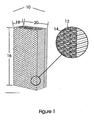
- Figure 5 shows a single sheet of the heat exchanger core wherein the pattern of corrugations follows a "herringbone" shape. Corrugations are set at an angle to the airflow (depicted by arrowed lines) as indicated by ridges 90 on one side of the sheet. Symmetrical about centreline 91, the angle of corrugations on the other side of line 91 are the mirror image as indicated by ridge line 94. Successive sheets in the heat exchanger stack are placed in the opposite direction such that the corrugation ridges intersect each other at an angle.
- an indirect evaporative cooler as herein described and exemplified by the embodiments shown in the drawings enables such a cooler to be made in which the channel elements are horizontal or approximately so, and ultimate cooling capacity of the cooler is determined by the height of the heat exchanger stack.
- a compact cooler can be constructed which has minimal projection from, say, a wall on which it is mounted.
- the preferred method of distributing water to the wet channels of the heat exchanger stack allows for reliable, periodic wetting of the channel surfaces with provision or capacity for the flushing of contaminants.
Description
- The present invention relates to counter flow indirect evaporative heat exchangers for evaporative coolers; for example, self contained air-conditioning units suitable for supplying cooled air to an enclosed space and also to self contained conditioning units suitable for supplying cooled water for use in heat exchange units forming part of a system for the cooling of enclosed spaces.
- Throughout this description and the claims which follow, unless the context requires otherwise, the word "comprise', or variations such as "comprises" or "comprising", will be understood to imply the inclusion of a stated integer or step or group of integers or steps.
- The reference to any prior art in this specification is not, and should not be taken as, an acknowledgement or any form of suggestion that that prior art forms part of the common general knowledge in Australia.
- The principles of indirect evaporative cooling have been well known for many years. Early references to the principle of pre-cooling air through a combination of heat exchange and evaporation prior to evaporative cooling include
SU 979796 by Maisotsenko US 4,977,753 by Maisotsenko , and as further refined inUS 6,581,402 ,US Application 2004/0226698 by Reinders and inWO 2006/074508 A1 by James . - The practical devices as shown in the aforementioned disclosures present a number of difficulties to be ameliorated before those devices can operate to a standard that is satisfactory for a commercially viable product.
- Of great practical importance in the provision of coolers is their size and shape which must be such as to fit and blend into the surroundings of, say, a domestic dwelling. While it has been traditional to mount direct evaporative coolers on rooves, the additional size and weight of indirect coolers of the same cooling capacity make this approach impractical. A similar problem presents itself when the working models of indirect evaporative coolers are positioned at ground level around the outside of a dwelling. The cooler may have a plan area which can be too large and use too much of the available space between, say, the wall of a building and a boundary fence.
- Marketing of indirect evaporative coolers would be greatly enhanced if a cooler could be fitted into a package to be mounted against the outside wall of a dwelling and had dimensions which satisfied the following criteria:
- A depth as small as practicable from the wall to the outside of the cooler.
- A width limited by handling considerations.
- A height only limited by clearance to the underside of any overhanging roof/eave members.
- An ideal configuration, consistent with technical requirements for its operation and, considering the above, would typically project from a wall, against which it is mounted, a distance of no more than about 600 mm, a width of up to 900 mm and height limited to about 2100 mm.
- The construction of a cooler within these parameters requires a radial departure from previously disclosed constructions of those devices. In all previous disclosures, certain dimensions of the heat exchanger core are defined by technical and/or practical restraints with only one dimension being able to be varied to increase the capacity of the heat exchanger.
- The Maisotsenko device shown in
US 6,581,402 has a heat exchanger width and depth restrained by air flow and resistance considerations where capacity is determined by the height of the exchanger. The configurations of Reinders and James have the depth and height of the heat exchanger determined by technical considerations, while the width determines the capacity of the device. We believe that if the favourable characteristics of each of these configurations could be combined into a device, then a much more practicable indirect cooler could be developed for the marketplace. - However, each of the previously disclosed configurations has other technical and practical difficulties which make a ready combination of their advantages somewhat problematic.
- The device disclosed in
US 6,581,402 requires horizontal heat exchanger plates with a wettable surface on one side and an impervious surface on the other. Water distribution throughout the wettable surface relies on a wickable media distributing water from a central trough with a combination of wicking along the surface and some gravitational assistance from a slight decline from the horizontal. Cooling to a low temperature requires water flow through the wetted surface to be as low as possible, and preferably just sufficient to replace the loss due to evaporation. Flushing of the wettable surfaces to remove any accumulation of salts left behind by evaporating water is not possible without significant degradation of the thermal performance of the air conditioner. - The Maisotsenko configuration, which progressively transfers a percentage of cooled air from the dry passage to the wet passage to provide evaporative cooling, compromises the temperature of the delivered air relative to other configurations, since the transferred air cannot be subjected to the full temperature difference offered by the heat exchanger.
- The configuration offered by Reinders fully exploits the original principles of indirect evaporative cooling, but the heat transfer performance of the heat exchanger is compromised by its layout and construction. Heat transferring from the wet passage side to the dry passage side has to travel through relatively long distances of heat exchanger material, necessitating the use of high conductivity materials such as metals to achieve reasonable performance.
- In both of the configurations used by Reinders and James, water distribution to the heat exchanger core is by irrigation of the top surface of the core, allowing water to flow down through the core to be collected in a reservoir below the core. This water flow through the core must be kept to a minimum while the cooler is in operation since any excess water flow over that required for evaporation will compromise the temperatures of the usable conditioned air that can be delivered by the cooler. The water flow requirement for thermal performance desirably includes the capability for it to flush residual salts from the core surfaces. A reasonable, practical compromise utilised by both Reinders and James is to periodically wet the core with an excess of water to flush out residual salts and fill the water retaining capability of the materials used to form the wet channels, followed by relatively long periods of operation without wetting. During this period, evaporation still takes place from water held in the wetted surfaces and full thermal performance of the cooler is achieved. This solution works well provided the wetting period is short, and the period between wettings is long.
- An alternative revealed by James is to divide the core into separately wetted segments, each segment with its own, thermally separated, water circuit (pump, reservoir and distributor). This method allows for constant flushing of the core without degradation of thermal performance. While this alternative has been demonstrated to work in practical models, it is difficult to implement in viable production models.
- A preferred solution is therefore to periodically wet the wet passages of the core with periods as long as possible between wettings to allow evaporation to take place and maximise the cooling capacity of the heat exchanger. This ideal becomes more difficult as the height of the heat exchanger is increased to take advantage of the preferred configuration of the overall indirect evaporative cooler. Water can only be added to the top of the core at a rate determined by the time it takes to trickle down through the wet passages. The wetting cycle must continue until water has spread through most of the vertical distance of the core, and to then be cut off allowing the excess water to flow all the way through the core and back to the reservoir. The cooling effect of the heat exchanger is compromised all the time that water is flowing through the wet passages, and only reverts to maximum cooling when all water flow has stopped. The taller the core, and hence the longer the wet passages, the longer will be the period required for wetting and the greater the proportion of time during which cooling is compromised. This situation becomes untenable with cores as tall as those required for the preferred geometry described above.
-
WO 2006/074508 A1 (James ) discloses an evaporative heat exchanger, having the precharacterizmg features of claim 1 or claim 2. - The present invention proposes an amelioration of the problems associated with the prior art by constructing a heat exchange core wherein the wet and dry passages are mounted near to horizontal and stacked alternately one above the other, and wherein there is provided an alternative method and means for periodically wetting the wet passages of the core.
- In accordance with a first aspect, the present invention provides a counter flow indirect evaporative heat exchanger having the characterizing features of claim 1.
In accordance with a second aspect, the present invention provides a counter flow indirect evaporative heat exchanger having the characterizing features of claim 2. - Preferably the wet and dry passages are constructed from corrugated sheets with one side comprising a wettable and absorbent medium and the other side comprising a water impermeable surface, membrane or layer.
- In one embodiment, the wet and dry passages are constructed from a wettable and absorbent cellulose base with an impermeable membrane applied to one surface.
- In an alternative embodiment, the wet and dry passages are constructed from a water impermeable formed sheet to which is applied a water absorbent media to one surface of the sheet.
- In a further embodiment the corrugated sheets to make each passage are assembled such that the corrugations of vertically adjacent sheets intersect at an angle in the range of 20° to 70°.
- In a still further embodiment, the corrugated sheets of the top and bottom of each passage are divided into two parts symmetrically about a centre-line substantially parallel to the mean airflow direction in each passage, with the corrugation angle in one part set at a complementary angle to the corrugation angle in the adjacent part.
- In a further enhancement, the corrugated sheets are constructed with the corrugations set in a herringbone angular pattern symmetrical about a centre line of each respective sheet.
- In a further enhancement of the second aspect the heat exchanger is constructed with a cavity space available for the incorporation of the slotted tubes so as to contain water delivered from the slot to the heat exchanger passages.
- One preferred form of desired wetting mechanism comprises a vertically traveling water spreader which wets a small plurality of passages of the core at the one time relative to the total number of passages of the core while undergoing movement to adjacent sections of the core until a complete wetting cycle of the core is completed. Preferably, vertical movement of the wetting mechanism between adjacent horizontal passages of the core is continuous. While a traveling water spreader is wetting a particular plurality of wet passages, the cooling efficiency of those passages is compromised by the flow of water therein. However, since the number of passages wetted at any one time is only a small proportion of the total number of wet passages in the whole core, the compromise to overall cooling is limited. The use of this mode of wetting allows heat exchange cores to be constructed with only structural or mechanical constraints as to height, thereby providing the flexibility required to provide an indirect evaporative cooler within desired size and shape constraints.
- In another aspect of the present invention there is provided an evaporative cooler having a counter flow indirect evaporative heat exchanger in accordance with the first or second aspect.
- A still further aspect of this invention provides a method of operating a counter flow indirect evaporative heat exchanger having a vertical stack of alternate substantially horizontal wet and dry passages in accordance with the first or second aspect.
- The construction of heat exchanger passages particularly suited for use in embodiments of the present invention includes corrugated sheets with a wettable surface and a water impermeable surface, with corrugation angles set at opposing angles as described in
WO 2006/074508 A1 , which disclosure is incorporated herein by reference. It will, however, be understood by a person skilled in the art that the principles of the present invention could equally be applied to other methods of construction of heat exchanger stacks or cores. - The present invention will now be described by way of example with reference to the accompanying drawings, in which:-
-
Figure 1 is an isometric view of a heat exchanger core of an indirect evaporative cooler as suited to an embodiment of this invention which has the proportions of being relatively tall compared to the plan dimensions thereof; -
Figure 2 shows a side elevation view of adjacent corrugated sheets in a heat exchanger having uniform corrugations; -
Figure 3 is a side elevation view of a heat exchanger core with a first water distribution mechanism; -
Figure 4 is a view similar to that ofFigure 3 but showing details of a second water distribution mechanism; and -
Figure 5 is a sectioned plan view through a heat exchanger stack or core showing an alternate layout of corrugations for a wet channel in the form of a herringbone pattern. - In
Figure 1 , the aspect ratio of the dimensions ofheat exchanger core 10 are such as to fit the preferred requirements of an indirect evaporative cooler.Dimension 16 is large compared to the dimensions 18 and 20. Typically,dimension 16 will be about 1,500 mm, dimension 20 about 900 mm and dimension 18 about 400 mm. Both the dry passages 12 (shown with horizontal shading) and wet passages 14 (shown with vertical shading) are orientated to be essentially horizontal, although it may be beneficial that they be slightly off horizontal to aid the distribution of water in the wet channels and the removal of excess water. - In
Figure 2 , theheat exchanger 10 is shown in front elevation withdry passages 12 andwet passages 14 orientated to be horizontal in use. Hot, dry intake air enters thedry passages 12 of the heat exchanger fromside 40 and leaves fromside 42 as cooled air. A proportion of air enters thewet passages 14 fromside 42 to flow back along the wet passages until it entersexhaust space 44, from which it is exhausted to atmosphere. This flow path through the core produces a useable stream of cool air fromside 42 being the proportion of air not passing back through thewet passages 14 to be exhausted viaspace 44. The means by which this arrangement cools the stream of useable air is described in previous publications, in particular seeWO 2006/074508 A1 . - In
Figure 3 , a traversing water distribution mechanism is shown withshrouds 52 covering a proportion of the delivery side of theheat exchanger 10. In operation, cooled air travels through thedry channels 12 of theheat exchanger 10, exiting alongface 51. In normal operation, a proportion of the air exiting fromdry channel 12 is diverted towet channel 14, the remainder if the cooled air fromdry channel 12 is available as useful air to be delivered by the cooler. However, when theshrouds 52 of thewater delivery mechanism 50 are covering a small number of the wet and dry channels on the delivery side, the air cannot split into 2 streams as in normal operation. The static pressure indry channel 12 will always be relatively high since the dry channel is connected directly to the space to be cooled which is pressurised by a fan (not shown). When air flow is interrupted by theshrouds 52, the static pressure in thewet channel 14 will drop since the wet channels are directly connected to the exhaust area of the heat exchanger, which is at normal atmospheric pressure. The end result of the interruption of flow by theshrouds 52 is that there will be an accelerated flow of air from thedry channel 12 to the adjacentwet channel 14 within the confines of theshrouds 52. - Water delivered via conduit 53 to
water nozzle 54, which is part of the traversingwater distribution mechanism 50, injects a water spray 58 into the accelerated air flow described above. The water thus sprayed can only flow through thewet channel 14, since the static pressure differences created by theshrouds 52 ensure that all air must flow from the dry channel to the wet channel. Thus all water sprayed is available to wet thewet channel 14, and water enteringwet channel 14 is distributed throughout the wet channel by the accelerated air flow therein. - Since the wet channels necessarily need to be periodically wetted, the water distribution mechanism must be traversed vertically up and down along the cooled
air delivery face 51 of the heat exchanger. By this means, a small number of wet channels are wetted at a time, with the means of wetting moving on to adjacent channels until the entire face has been traversed and all wet channels have been wetted. - One method of traversing the water distribution mechanism is illustrated in
Figure 3 . The water distribution mechanism is attached to a threadednut 62, which runs on anextended screw 60. When thescrew 60 is driven in reciprocal directions by a driving means (such as an electric motor, not shown), the water distributing mechanism will move over the delivery face of the heat exchanger. - An alternative water distribution mechanism is illustrated in
Figure 4 . Water is conducted through ahollow conduit 70, which has a slot along its length on the side facing the delivery face of theheat exchanger 10. Inside thehollow conduit 70 is a slidingplug 76, held in position by a continuous belt or chain 72. Flexible belt 72 is positioned bycapstans 74, driven by, say, an electric motor such that the drive of the capstan causes the slidingplug 76 to move up and down withinconduit 70. - In operation,
water 78 is directed down theconduit 70 from the top. Thewater 78 flows downconduit 70 until it impacts on slidingplug 76. The slidingplug 76 diverts the water flow through the slot inconduit 70 at the position of slidingplug 76. Since the slot ofconduit 70 is positioned against the delivery face ofheat exchanger 10, as shown in Section A-A, the water so diverted will impinge on a small proportion of both the wet and dry channels at the position of theplug 76. Since air is flowing out of the dry channels and into the wet channels along the delivery face ofheat exchanger 10, the water diverted onto the delivery face ofheat exchanger 10 will tend to flow into the wet channels only, thereby providing the means of wetting the internal surfaces of the wet channel. The effect at the dry channel, wherein no water flows against the direction of air flow is shown in Section B-B. As slidingplug 76 progresses up and down the face ofheat exchanger 10, all the wet channels will be progressively wetted during a wetting cycle. - A preferred arrangement for transmitting water diverted by
plug 76 into theheat exchanger 10 is illustrated in section Alt A-A. In this arrangement,heat exchanger 10 is constructed with notches 80 on thedelivery face 51 such that the slot inconduit 70 is contained within the notch of the heat exchanger. The water delivered to the heat exchanger by the slidingplug 76 is contained within the notch 80 greatly reducing the tendency to spray water into the delivered air space (42 inFigure 2 ) when it impacts the delivery face of the heat exchanger at high velocity. - The method and means of applying water to the wet channels of the heat exchanger described above are designed to apply water to the wet channels at a rate much greater than is actually required for evaporation. Such a high flow rate is required for the purposes of flushing salt deposits and contaminants from the surfaces of the wet channels, and to ensure that all the internal surfaces of the wet channels are indeed wetted. This introduces a practical problem with the channels of the heat exchanger being horizontal, and constructed from corrugated paper set at an angle to the air flow as described in
WO 2006/074508 A1 . The angle of the corrugations tend to bias all the water flow (which tends to cling to the lower surfaces of the channels) in the direction of the angle of the corrugation. Since the wet and dry channels alternate the angles of the corrugations, the net result is that all the lower surfaces of the wet channels have corrugations in the same direction and tend to direct the water in the channel to one side only. This results in difficulty in wetting the wet channels uniformly and leads to an excess of water exiting through theexhaust space 44 on one side only rather than distributing the excess water through both of the exhaust spaces. - These difficulties can be greatly relieved by adopting a construction of the layers of the heat exchanger core as illustrated in
Figure 5. Figure 5 shows a single sheet of the heat exchanger core wherein the pattern of corrugations follows a "herringbone" shape. Corrugations are set at an angle to the airflow (depicted by arrowed lines) as indicated byridges 90 on one side of the sheet. Symmetrical aboutcentreline 91, the angle of corrugations on the other side ofline 91 are the mirror image as indicated byridge line 94. Successive sheets in the heat exchanger stack are placed in the opposite direction such that the corrugation ridges intersect each other at an angle. In operation, if the illustration ofFigure 5 represents the bottom sheet of a wet channel, air enters the channel fromchamber 42 and flows through the space between the corrugation ridges and valleys of adjacent sheets. The air is then exhausted throughexhaust ports 44. When water is introduced symmetrically aboutcentre line 91 bywater distributors 50, into the wet channel so formed, half of the water enters a wet channel with the corrugation bias in one direction; the other half enters with the corrugation bias in the opposite direction. Thus there is no tendency for all the water to flow towards one ofexhaust spaces 44 rather than the other. Wetting is more uniform, and excess water flow from theexhaust ports 44 can be kept to manageable levels. - The construction of an indirect evaporative cooler as herein described and exemplified by the embodiments shown in the drawings enables such a cooler to be made in which the channel elements are horizontal or approximately so, and ultimate cooling capacity of the cooler is determined by the height of the heat exchanger stack. Thus a compact cooler can be constructed which has minimal projection from, say, a wall on which it is mounted. The preferred method of distributing water to the wet channels of the heat exchanger stack allows for reliable, periodic wetting of the channel surfaces with provision or capacity for the flushing of contaminants.
Claims (14)
- A counter flow indirect evaporative heat exchanger (10) wherein vertically adjacent counter flow wet and dry passages (14, 12) are, when in use, orientated to be horizontal or near to horizontal, wherein the wet passages (14) are wetted by wetting means which sequentially applies water elongately to the wet passages (14) across the height of the heat exchanger (10), characterized in that said wetting means includes a water delivery device adapted to travel generally vertically of the heat exchanger (10) for delivering water directly into a small plurality of the total number of wet passages (14) at a time along an air delivery face (51) of the heat exchanger (10).
- A counter flow indirect evaporative heat exchanger (10) wherein. vertifically adjacent counter flow wet and dry passages (14, 12) are, when in use, orientated to be horizontal or near to horizontal, wherein the wet passages (14) are wetted by wetting means which sequentially applies water elongately to the wet passages (14) across the height of the heat exchanger (10), characterizing in that said water delivery device comprises a plurality of tubes (70) placed vertically along an air delivery face (51) of the heat exchanger (10), said tubes (70) having slots in the tubes facing toward the air delivery face (51), and wherein a sliding plug (76) is adapted to traverse up and down each slotted tube (30) such that as water is delivered into the top of each tube (70) the location of the sliding plug (76) in each tube (70) defines where water is delivered from each tube (70) to wet passages (14) of the heat exchanger (10).
- A heat exchanger (10) as claimed in claim 1 or 2, wherein the Wet and dry passages (14, 12) are constructed from corrugated sheets with one side comprising a wettable and absorbent medium and the other side comprising a water impermeable surface, membrane or layer.
- A heat exchanger, (10) as claimed in claim 1,2 or 3, wherein the wet and dry passages (14, 12) are constructed from a wettable and absorbent cellulose base with an impermeable membrane applied to one surface.
- A heat exchanger (10) as claimed in claim 1, 2 or 3, wherein the wet and dry passages (14, 12) are constructed from a water impermeable formed sheet to which is applied a water absorbent media to one surface of the sheet.
- A heat exchanger (10) as claimed in claim 3 or claim 4 or 5 when appended to claim 3, wherein the corrugated sheets to make each passage (14, 12) are assembled such that the corrugations of vertically adjacent sheets intersect at an angle in the range of 20° to 70°.
- A heat exchanger (10) as claimed in claim 6, wherein the corrugated sheets of the top and bottom of each passage (14, 12) are divided into two parts symmetrically about a centre-line substantially parallel to a mean airflow direction in each passage (14, 12), with the corrugation angle in one part set at a complementary angle to the corrugation angle in the adjacent part.
- A heat exchanger (10) as claimed in claim 6 or 7, wherein the corrugated sheets are constructed with the corrugations set in a herringbone angular pattern symmetrical about a centre line of each respective sheet.
- A heat exchanger as claimed in any one of the preceding claims when dependent on at least claim 2, including cavity spaces or recesses along the air delivery face (51) shaped to fit the slotted tubes (30) to thereby contain water delivered to the heat exchanger passages (14).
- A heat exchanger (10) as claimed in any one of the preceding claims when dependent on at least claim 1, wherein the water delivery device comprises a vertically moveable water spreader adapted to wet a small plurality of a total number of passages at a time along an air delivery face (51) of the heat exchanger.
- A heat exchanger as claimed in claim 10, wherein vertical movement of the water spreader is continuous during a wetting cycle.
- A heat exchanger as claimed in claim 10 or 11, wherein water is continuously dispensed by the water spreader during a wetting cycle.
- An evaporative cooler having a counter flow indirect evaporative heat exchanger (10) as claimed in any one of the preceding claims.
- A method of operating a counter flow indirect evaporative heat exchanger (10) according to any one of the proceding claims, the heat exchanger (10) having a vertical stack of alternate substantially horizontal wet and dry passages (14, 12), comprising cyclically elongated wetting a small plurality of the total number of said wet passages (14) at any one time as said wet passages (14) approach a drying out state during air flow through the heat exchanger (10).
Applications Claiming Priority (2)
| Application Number | Priority Date | Filing Date | Title |
|---|---|---|---|
| AU2008905875A AU2008905875A0 (en) | 2008-11-13 | Indirect Evaporative Cooler construction | |
| PCT/AU2009/001463 WO2010054426A1 (en) | 2008-11-13 | 2009-11-10 | Indirect evaporative cooler construction |
Publications (4)
| Publication Number | Publication Date |
|---|---|
| EP2362933A1 EP2362933A1 (en) | 2011-09-07 |
| EP2362933A4 EP2362933A4 (en) | 2014-03-12 |
| EP2362933B1 true EP2362933B1 (en) | 2015-12-16 |
| EP2362933B8 EP2362933B8 (en) | 2016-02-24 |
Family
ID=42169527
Family Applications (1)
| Application Number | Title | Priority Date | Filing Date |
|---|---|---|---|
| EP09825644.9A Active EP2362933B8 (en) | 2008-11-13 | 2009-11-10 | Counter flow indirect evaporative heat exchanger |
Country Status (10)
| Country | Link |
|---|---|
| US (1) | US8783054B2 (en) |
| EP (1) | EP2362933B8 (en) |
| CN (1) | CN102272535B (en) |
| AU (1) | AU2009316228B2 (en) |
| CA (1) | CA2745336A1 (en) |
| ES (1) | ES2564817T3 (en) |
| IL (1) | IL213183A (en) |
| PT (1) | PT2362933E (en) |
| WO (1) | WO2010054426A1 (en) |
| ZA (1) | ZA201104578B (en) |
Families Citing this family (12)
| Publication number | Priority date | Publication date | Assignee | Title |
|---|---|---|---|---|
| AU2013200027B2 (en) * | 2012-01-04 | 2016-09-08 | Seeley International Pty. Ltd. | Scaleable Capacity Indirect Evaporative Cooler |
| US9234705B2 (en) * | 2013-01-03 | 2016-01-12 | F.F. Seeley Nominees Pty Ltd | Scaleable capacity indirect evaporative cooler |
| CN103968678B (en) * | 2014-05-05 | 2016-04-06 | 中国神华能源股份有限公司 | Harmon formula indirect air cooling spray cooling system |
| US20170276383A1 (en) * | 2014-09-08 | 2017-09-28 | Seeley International Pty Ltd | Compact indirect evaporative cooler |
| RU2694379C1 (en) | 2015-06-22 | 2019-07-12 | Дач Инновейшн Ин Эр Тритмент Бв | Building equipped with air treatment system |
| US10422540B2 (en) * | 2015-10-05 | 2019-09-24 | Matthew Morris | Evaporative cooling device and control system |
| CN107543438A (en) * | 2016-06-28 | 2018-01-05 | 陈祖卫 | Diaphragm type dew point indirect evaporative cooling heat exchanger |
| JP6615080B2 (en) * | 2016-10-31 | 2019-12-04 | 三菱電機株式会社 | Humidifier, ventilator and air conditioner |
| MX2021003780A (en) | 2018-10-02 | 2021-09-08 | Harvard College | Hydrophobic barrier layer for ceramic indirect evaporative cooling systems. |
| CN111023863B (en) * | 2019-12-25 | 2021-07-30 | 深圳市辰诺节能科技有限公司 | Water vector spraying propulsion ventilation cooling tower capable of changing spraying angle |
| CN111365797A (en) * | 2020-02-28 | 2020-07-03 | 徐州申恒环境科技有限公司 | Folding plate type indirect evaporative cooling equipment for textile air conditioner and working mode thereof |
| ES2933748B2 (en) * | 2021-08-10 | 2023-08-03 | Univ Cordoba | Ultra-compact, high-efficiency heat exchanger for simultaneous treatment of air temperature and humidity |
Family Cites Families (20)
| Publication number | Priority date | Publication date | Assignee | Title |
|---|---|---|---|---|
| SE383777B (en) | 1973-07-18 | 1976-03-29 | Munters Ab Carl | KIT AND DEVICE FOR AIR COOLING |
| SE415928B (en) * | 1979-01-17 | 1980-11-10 | Alfa Laval Ab | PLATTVERMEVEXLARE |
| US4660390A (en) | 1986-03-25 | 1987-04-28 | Worthington Mark N | Air conditioner with three stages of indirect regeneration |
| RU1778453C (en) | 1987-05-12 | 1992-11-30 | Одесский Инженерно-Строительный Институт | Method of processing air in room |
| US5349829A (en) * | 1992-05-21 | 1994-09-27 | Aoc, Inc. | Method and apparatus for evaporatively cooling gases and/or fluids |
| AUPM777294A0 (en) * | 1994-08-30 | 1994-09-22 | William Allen Trusts Pty Ltd | Spaced evaporative wicks within an air cooler |
| DE29506110U1 (en) * | 1995-01-20 | 1995-08-17 | Polybloc Ag | Plate heat exchanger with wetting device |
| AUPN123495A0 (en) * | 1995-02-20 | 1995-03-16 | F F Seeley Nominees Pty Ltd | Contra flow heat exchanger |
| IL113078A0 (en) | 1995-03-22 | 1995-06-29 | Coolsys Maarachot Keroor Mitka | Air cooler |
| EP0773412B1 (en) | 1995-11-07 | 2003-12-17 | Kabushiki Kaisha Seibu Giken | A method and a device for refrigeration of fluid and desiccative refrigeration of gas |
| JPH11187220A (en) * | 1997-12-17 | 1999-07-09 | Seiko Instruments Inc | Color image reader |
| WO1999041552A1 (en) * | 1998-02-13 | 1999-08-19 | Antonius Van Hecke | Method and device for cooling air |
| US6523604B1 (en) * | 1998-11-06 | 2003-02-25 | Barry R. Brooks | Indirect evaporative cooling apparatus |
| AU9488201A (en) | 2000-09-27 | 2002-04-08 | Idalex Technologies Inc | Method and plate apparatus for dew point evaporative cooler |
| NL1018735C1 (en) | 2001-08-10 | 2003-02-11 | Forest Air B V | Heat exchanger, has walls provided with hydrophilic coating formed chemically from aqueous solution |
| US20040061245A1 (en) | 2002-08-05 | 2004-04-01 | Valeriy Maisotsenko | Indirect evaporative cooling mechanism |
| GB0415549D0 (en) * | 2004-07-12 | 2004-08-11 | Oxycell Holding Bv | Heat exchange device |
| CN101102888B (en) * | 2005-01-11 | 2011-01-19 | Ff西里·诺明西斯有限公司 | Method and materials for improving evaporative heat exchangers |
| CN101191646B (en) * | 2006-11-30 | 2011-08-24 | 新疆绿色使者空气环境技术有限公司 | Evaporation refrigerating water chilling unit |
| CN101266091B (en) * | 2008-04-14 | 2010-10-27 | 西安工程大学 | Porous functional ceramic dew point plate fin type indirect evaporative cooler |
-
2009
- 2009-11-10 US US13/142,901 patent/US8783054B2/en active Active
- 2009-11-10 ES ES09825644.9T patent/ES2564817T3/en active Active
- 2009-11-10 AU AU2009316228A patent/AU2009316228B2/en active Active
- 2009-11-10 WO PCT/AU2009/001463 patent/WO2010054426A1/en active Application Filing
- 2009-11-10 EP EP09825644.9A patent/EP2362933B8/en active Active
- 2009-11-10 CA CA2745336A patent/CA2745336A1/en not_active Abandoned
- 2009-11-10 PT PT98256449T patent/PT2362933E/en unknown
- 2009-11-10 CN CN200980154068.2A patent/CN102272535B/en active Active
-
2011
- 2011-05-26 IL IL213183A patent/IL213183A/en active IP Right Grant
- 2011-06-21 ZA ZA2011/04578A patent/ZA201104578B/en unknown
Also Published As
| Publication number | Publication date |
|---|---|
| AU2009316228A1 (en) | 2010-05-20 |
| EP2362933A1 (en) | 2011-09-07 |
| CN102272535A (en) | 2011-12-07 |
| PT2362933E (en) | 2016-03-04 |
| ES2564817T3 (en) | 2016-03-29 |
| WO2010054426A1 (en) | 2010-05-20 |
| IL213183A (en) | 2014-03-31 |
| AU2009316228B2 (en) | 2015-10-22 |
| EP2362933A4 (en) | 2014-03-12 |
| ZA201104578B (en) | 2012-03-28 |
| CA2745336A1 (en) | 2010-05-20 |
| EP2362933B8 (en) | 2016-02-24 |
| IL213183A0 (en) | 2011-07-31 |
| US8783054B2 (en) | 2014-07-22 |
| CN102272535B (en) | 2014-07-30 |
| US20110302946A1 (en) | 2011-12-15 |
Similar Documents
| Publication | Publication Date | Title |
|---|---|---|
| EP2362933B1 (en) | Counter flow indirect evaporative heat exchanger | |
| CN101102888B (en) | Method and materials for improving evaporative heat exchangers | |
| KR101497297B1 (en) | Evaporative cooling device | |
| US20110041531A1 (en) | Evaporative cooler | |
| CA2554512C (en) | Plate heat and mass exchanger with edge extension | |
| CA2423472A1 (en) | Method and plate apparatus for dew point evaporative cooler | |
| JP3348848B2 (en) | Indirect evaporative cooling system | |
| US20190346221A1 (en) | Cooling tower water distribution system | |
| KR101054445B1 (en) | Regenerative evaporative air conditioners, air conditioning systems and their core modules | |
| AU2010201392B2 (en) | Method and Means for Operating Evaporative Coolers | |
| WO2018051157A1 (en) | Water distribution systems for plate heat and mass exchanger for indirect evaportive cooling |
Legal Events
| Date | Code | Title | Description |
|---|---|---|---|
| PUAI | Public reference made under article 153(3) epc to a published international application that has entered the european phase |
Free format text: ORIGINAL CODE: 0009012 |
|
| 17P | Request for examination filed |
Effective date: 20110602 |
|
| AK | Designated contracting states |
Kind code of ref document: A1 Designated state(s): AT BE BG CH CY CZ DE DK EE ES FI FR GB GR HR HU IE IS IT LI LT LU LV MC MK MT NL NO PL PT RO SE SI SK SM TR |
|
| DAX | Request for extension of the european patent (deleted) | ||
| A4 | Supplementary search report drawn up and despatched |
Effective date: 20140211 |
|
| RIC1 | Information provided on ipc code assigned before grant |
Ipc: F28D 9/00 20060101ALI20140205BHEP Ipc: F24F 6/04 20060101ALI20140205BHEP Ipc: F28F 3/08 20060101ALI20140205BHEP Ipc: F24F 12/00 20060101AFI20140205BHEP Ipc: F28D 5/00 20060101ALI20140205BHEP |
|
| 17Q | First examination report despatched |
Effective date: 20141027 |
|
| GRAP | Despatch of communication of intention to grant a patent |
Free format text: ORIGINAL CODE: EPIDOSNIGR1 |
|
| INTG | Intention to grant announced |
Effective date: 20150612 |
|
| GRAS | Grant fee paid |
Free format text: ORIGINAL CODE: EPIDOSNIGR3 |
|
| GRAA | (expected) grant |
Free format text: ORIGINAL CODE: 0009210 |
|
| AK | Designated contracting states |
Kind code of ref document: B1 Designated state(s): AT BE BG CH CY CZ DE DK EE ES FI FR GB GR HR HU IE IS IT LI LT LU LV MC MK MT NL NO PL PT RO SE SI SK SM TR |
|
| REG | Reference to a national code |
Ref country code: GB Ref legal event code: FG4D |
|
| REG | Reference to a national code |
Ref country code: CH Ref legal event code: EP |
|
| REG | Reference to a national code |
Ref country code: IE Ref legal event code: FG4D |
|
| REG | Reference to a national code |
Ref country code: AT Ref legal event code: REF Ref document number: 765749 Country of ref document: AT Kind code of ref document: T Effective date: 20160115 |
|
| RAP2 | Party data changed (patent owner data changed or rights of a patent transferred) |
Owner name: F.F. SEELEY NOMINEES PTY LTD. |
|
| REG | Reference to a national code |
Ref country code: DE Ref legal event code: R096 Ref document number: 602009035306 Country of ref document: DE |
|
| REG | Reference to a national code |
Ref country code: PT Ref legal event code: SC4A Free format text: AVAILABILITY OF NATIONAL TRANSLATION Effective date: 20160128 |
|
| REG | Reference to a national code |
Ref country code: ES Ref legal event code: FG2A Ref document number: 2564817 Country of ref document: ES Kind code of ref document: T3 Effective date: 20160329 |
|
| REG | Reference to a national code |
Ref country code: NL Ref legal event code: MP Effective date: 20151216 |
|
| REG | Reference to a national code |
Ref country code: LT Ref legal event code: MG4D |
|
| PG25 | Lapsed in a contracting state [announced via postgrant information from national office to epo] |
Ref country code: NO Free format text: LAPSE BECAUSE OF FAILURE TO SUBMIT A TRANSLATION OF THE DESCRIPTION OR TO PAY THE FEE WITHIN THE PRESCRIBED TIME-LIMIT Effective date: 20160316 Ref country code: HR Free format text: LAPSE BECAUSE OF FAILURE TO SUBMIT A TRANSLATION OF THE DESCRIPTION OR TO PAY THE FEE WITHIN THE PRESCRIBED TIME-LIMIT Effective date: 20151216 Ref country code: LT Free format text: LAPSE BECAUSE OF FAILURE TO SUBMIT A TRANSLATION OF THE DESCRIPTION OR TO PAY THE FEE WITHIN THE PRESCRIBED TIME-LIMIT Effective date: 20151216 |
|
| REG | Reference to a national code |
Ref country code: AT Ref legal event code: MK05 Ref document number: 765749 Country of ref document: AT Kind code of ref document: T Effective date: 20151216 |
|
| PG25 | Lapsed in a contracting state [announced via postgrant information from national office to epo] |
Ref country code: NL Free format text: LAPSE BECAUSE OF FAILURE TO SUBMIT A TRANSLATION OF THE DESCRIPTION OR TO PAY THE FEE WITHIN THE PRESCRIBED TIME-LIMIT Effective date: 20151216 Ref country code: FI Free format text: LAPSE BECAUSE OF FAILURE TO SUBMIT A TRANSLATION OF THE DESCRIPTION OR TO PAY THE FEE WITHIN THE PRESCRIBED TIME-LIMIT Effective date: 20151216 Ref country code: LV Free format text: LAPSE BECAUSE OF FAILURE TO SUBMIT A TRANSLATION OF THE DESCRIPTION OR TO PAY THE FEE WITHIN THE PRESCRIBED TIME-LIMIT Effective date: 20151216 Ref country code: SE Free format text: LAPSE BECAUSE OF FAILURE TO SUBMIT A TRANSLATION OF THE DESCRIPTION OR TO PAY THE FEE WITHIN THE PRESCRIBED TIME-LIMIT Effective date: 20151216 |
|
| REG | Reference to a national code |
Ref country code: GR Ref legal event code: EP Ref document number: 20160400490 Country of ref document: GR Effective date: 20160505 |
|
| PG25 | Lapsed in a contracting state [announced via postgrant information from national office to epo] |
Ref country code: CZ Free format text: LAPSE BECAUSE OF FAILURE TO SUBMIT A TRANSLATION OF THE DESCRIPTION OR TO PAY THE FEE WITHIN THE PRESCRIBED TIME-LIMIT Effective date: 20151216 |
|
| PG25 | Lapsed in a contracting state [announced via postgrant information from national office to epo] |
Ref country code: RO Free format text: LAPSE BECAUSE OF FAILURE TO SUBMIT A TRANSLATION OF THE DESCRIPTION OR TO PAY THE FEE WITHIN THE PRESCRIBED TIME-LIMIT Effective date: 20151216 Ref country code: EE Free format text: LAPSE BECAUSE OF FAILURE TO SUBMIT A TRANSLATION OF THE DESCRIPTION OR TO PAY THE FEE WITHIN THE PRESCRIBED TIME-LIMIT Effective date: 20151216 Ref country code: AT Free format text: LAPSE BECAUSE OF FAILURE TO SUBMIT A TRANSLATION OF THE DESCRIPTION OR TO PAY THE FEE WITHIN THE PRESCRIBED TIME-LIMIT Effective date: 20151216 Ref country code: IS Free format text: LAPSE BECAUSE OF FAILURE TO SUBMIT A TRANSLATION OF THE DESCRIPTION OR TO PAY THE FEE WITHIN THE PRESCRIBED TIME-LIMIT Effective date: 20160416 Ref country code: SK Free format text: LAPSE BECAUSE OF FAILURE TO SUBMIT A TRANSLATION OF THE DESCRIPTION OR TO PAY THE FEE WITHIN THE PRESCRIBED TIME-LIMIT Effective date: 20151216 Ref country code: SM Free format text: LAPSE BECAUSE OF FAILURE TO SUBMIT A TRANSLATION OF THE DESCRIPTION OR TO PAY THE FEE WITHIN THE PRESCRIBED TIME-LIMIT Effective date: 20151216 |
|
| REG | Reference to a national code |
Ref country code: DE Ref legal event code: R097 Ref document number: 602009035306 Country of ref document: DE |
|
| PLBE | No opposition filed within time limit |
Free format text: ORIGINAL CODE: 0009261 |
|
| STAA | Information on the status of an ep patent application or granted ep patent |
Free format text: STATUS: NO OPPOSITION FILED WITHIN TIME LIMIT |
|
| REG | Reference to a national code |
Ref country code: FR Ref legal event code: PLFP Year of fee payment: 8 |
|
| PG25 | Lapsed in a contracting state [announced via postgrant information from national office to epo] |
Ref country code: DK Free format text: LAPSE BECAUSE OF FAILURE TO SUBMIT A TRANSLATION OF THE DESCRIPTION OR TO PAY THE FEE WITHIN THE PRESCRIBED TIME-LIMIT Effective date: 20151216 Ref country code: PL Free format text: LAPSE BECAUSE OF FAILURE TO SUBMIT A TRANSLATION OF THE DESCRIPTION OR TO PAY THE FEE WITHIN THE PRESCRIBED TIME-LIMIT Effective date: 20151216 |
|
| 26N | No opposition filed |
Effective date: 20160919 |
|
| PG25 | Lapsed in a contracting state [announced via postgrant information from national office to epo] |
Ref country code: BE Free format text: LAPSE BECAUSE OF FAILURE TO SUBMIT A TRANSLATION OF THE DESCRIPTION OR TO PAY THE FEE WITHIN THE PRESCRIBED TIME-LIMIT Effective date: 20151216 |
|
| PG25 | Lapsed in a contracting state [announced via postgrant information from national office to epo] |
Ref country code: SI Free format text: LAPSE BECAUSE OF FAILURE TO SUBMIT A TRANSLATION OF THE DESCRIPTION OR TO PAY THE FEE WITHIN THE PRESCRIBED TIME-LIMIT Effective date: 20151216 |
|
| REG | Reference to a national code |
Ref country code: DE Ref legal event code: R119 Ref document number: 602009035306 Country of ref document: DE |
|
| REG | Reference to a national code |
Ref country code: CH Ref legal event code: PL |
|
| PG25 | Lapsed in a contracting state [announced via postgrant information from national office to epo] |
Ref country code: CH Free format text: LAPSE BECAUSE OF NON-PAYMENT OF DUE FEES Effective date: 20161130 Ref country code: LI Free format text: LAPSE BECAUSE OF NON-PAYMENT OF DUE FEES Effective date: 20161130 |
|
| REG | Reference to a national code |
Ref country code: IE Ref legal event code: MM4A |
|
| PG25 | Lapsed in a contracting state [announced via postgrant information from national office to epo] |
Ref country code: LU Free format text: LAPSE BECAUSE OF NON-PAYMENT OF DUE FEES Effective date: 20161130 |
|
| REG | Reference to a national code |
Ref country code: FR Ref legal event code: PLFP Year of fee payment: 9 |
|
| PG25 | Lapsed in a contracting state [announced via postgrant information from national office to epo] |
Ref country code: IE Free format text: LAPSE BECAUSE OF NON-PAYMENT OF DUE FEES Effective date: 20161110 Ref country code: DE Free format text: LAPSE BECAUSE OF NON-PAYMENT OF DUE FEES Effective date: 20170601 |
|
| PG25 | Lapsed in a contracting state [announced via postgrant information from national office to epo] |
Ref country code: HU Free format text: LAPSE BECAUSE OF FAILURE TO SUBMIT A TRANSLATION OF THE DESCRIPTION OR TO PAY THE FEE WITHIN THE PRESCRIBED TIME-LIMIT; INVALID AB INITIO Effective date: 20091110 Ref country code: CY Free format text: LAPSE BECAUSE OF FAILURE TO SUBMIT A TRANSLATION OF THE DESCRIPTION OR TO PAY THE FEE WITHIN THE PRESCRIBED TIME-LIMIT Effective date: 20151216 |
|
| PG25 | Lapsed in a contracting state [announced via postgrant information from national office to epo] |
Ref country code: MK Free format text: LAPSE BECAUSE OF FAILURE TO SUBMIT A TRANSLATION OF THE DESCRIPTION OR TO PAY THE FEE WITHIN THE PRESCRIBED TIME-LIMIT Effective date: 20151216 Ref country code: MC Free format text: LAPSE BECAUSE OF FAILURE TO SUBMIT A TRANSLATION OF THE DESCRIPTION OR TO PAY THE FEE WITHIN THE PRESCRIBED TIME-LIMIT Effective date: 20151216 |
|
| PG25 | Lapsed in a contracting state [announced via postgrant information from national office to epo] |
Ref country code: BG Free format text: LAPSE BECAUSE OF FAILURE TO SUBMIT A TRANSLATION OF THE DESCRIPTION OR TO PAY THE FEE WITHIN THE PRESCRIBED TIME-LIMIT Effective date: 20151216 |
|
| REG | Reference to a national code |
Ref country code: FR Ref legal event code: PLFP Year of fee payment: 10 |
|
| PG25 | Lapsed in a contracting state [announced via postgrant information from national office to epo] |
Ref country code: MT Free format text: LAPSE BECAUSE OF NON-PAYMENT OF DUE FEES Effective date: 20161110 |
|
| PGFP | Annual fee paid to national office [announced via postgrant information from national office to epo] |
Ref country code: ES Payment date: 20230224 Year of fee payment: 14 |
|
| PGFP | Annual fee paid to national office [announced via postgrant information from national office to epo] |
Ref country code: TR Payment date: 20230925 Year of fee payment: 15 Ref country code: GB Payment date: 20230919 Year of fee payment: 15 |
|
| PGFP | Annual fee paid to national office [announced via postgrant information from national office to epo] |
Ref country code: PT Payment date: 20230921 Year of fee payment: 15 Ref country code: FR Payment date: 20230919 Year of fee payment: 15 |
|
| PGFP | Annual fee paid to national office [announced via postgrant information from national office to epo] |
Ref country code: GR Payment date: 20231129 Year of fee payment: 15 |
|
| PGFP | Annual fee paid to national office [announced via postgrant information from national office to epo] |
Ref country code: IT Payment date: 20230922 Year of fee payment: 15 |
|
| PGFP | Annual fee paid to national office [announced via postgrant information from national office to epo] |
Ref country code: ES Payment date: 20231229 Year of fee payment: 15 |