EP2362462A1 - Power supply device with battery cell cooling mechanism and vehicle including the same - Google Patents
Power supply device with battery cell cooling mechanism and vehicle including the same Download PDFInfo
- Publication number
- EP2362462A1 EP2362462A1 EP20110000625 EP11000625A EP2362462A1 EP 2362462 A1 EP2362462 A1 EP 2362462A1 EP 20110000625 EP20110000625 EP 20110000625 EP 11000625 A EP11000625 A EP 11000625A EP 2362462 A1 EP2362462 A1 EP 2362462A1
- Authority
- EP
- European Patent Office
- Prior art keywords
- battery
- power supply
- temperature equalizing
- supply device
- battery cells
- Prior art date
- Legal status (The legal status is an assumption and is not a legal conclusion. Google has not performed a legal analysis and makes no representation as to the accuracy of the status listed.)
- Withdrawn
Links
- 238000001816 cooling Methods 0.000 title claims abstract description 90
- 230000007246 mechanism Effects 0.000 title description 8
- 239000000112 cooling gas Substances 0.000 claims abstract description 97
- 238000003780 insertion Methods 0.000 claims abstract description 72
- 230000037431 insertion Effects 0.000 claims abstract description 72
- 230000008878 coupling Effects 0.000 claims abstract description 38
- 238000010168 coupling process Methods 0.000 claims abstract description 38
- 238000005859 coupling reaction Methods 0.000 claims abstract description 38
- 238000011144 upstream manufacturing Methods 0.000 claims abstract description 23
- 229910052751 metal Inorganic materials 0.000 claims description 17
- 239000002184 metal Substances 0.000 claims description 17
- 238000005452 bending Methods 0.000 claims description 4
- 230000007423 decrease Effects 0.000 claims description 4
- 239000007789 gas Substances 0.000 abstract description 2
- 238000010276 construction Methods 0.000 description 30
- 238000007599 discharging Methods 0.000 description 13
- 239000008186 active pharmaceutical agent Substances 0.000 description 9
- 238000007664 blowing Methods 0.000 description 6
- 230000006866 deterioration Effects 0.000 description 5
- 238000010586 diagram Methods 0.000 description 5
- 238000004519 manufacturing process Methods 0.000 description 5
- 230000000694 effects Effects 0.000 description 4
- 238000003860 storage Methods 0.000 description 4
- 238000003466 welding Methods 0.000 description 4
- 230000008901 benefit Effects 0.000 description 3
- 239000013256 coordination polymer Substances 0.000 description 3
- 239000012777 electrically insulating material Substances 0.000 description 3
- 238000000034 method Methods 0.000 description 3
- 240000004282 Grewia occidentalis Species 0.000 description 2
- 239000000853 adhesive Substances 0.000 description 2
- 230000001070 adhesive effect Effects 0.000 description 2
- 230000004888 barrier function Effects 0.000 description 2
- 230000008859 change Effects 0.000 description 2
- 238000004891 communication Methods 0.000 description 2
- 239000002826 coolant Substances 0.000 description 2
- 238000000465 moulding Methods 0.000 description 2
- 230000001172 regenerating effect Effects 0.000 description 2
- 230000001105 regulatory effect Effects 0.000 description 2
- 230000003014 reinforcing effect Effects 0.000 description 2
- 229920005989 resin Polymers 0.000 description 2
- 239000011347 resin Substances 0.000 description 2
- 125000006850 spacer group Chemical group 0.000 description 2
- 241000196324 Embryophyta Species 0.000 description 1
- HBBGRARXTFLTSG-UHFFFAOYSA-N Lithium ion Chemical compound [Li+] HBBGRARXTFLTSG-UHFFFAOYSA-N 0.000 description 1
- 230000001133 acceleration Effects 0.000 description 1
- 229910052782 aluminium Inorganic materials 0.000 description 1
- XAGFODPZIPBFFR-UHFFFAOYSA-N aluminium Chemical compound [Al] XAGFODPZIPBFFR-UHFFFAOYSA-N 0.000 description 1
- OJIJEKBXJYRIBZ-UHFFFAOYSA-N cadmium nickel Chemical compound [Ni].[Cd] OJIJEKBXJYRIBZ-UHFFFAOYSA-N 0.000 description 1
- 239000013013 elastic material Substances 0.000 description 1
- 229920006015 heat resistant resin Polymers 0.000 description 1
- 239000001257 hydrogen Substances 0.000 description 1
- 229910052739 hydrogen Inorganic materials 0.000 description 1
- 238000009413 insulation Methods 0.000 description 1
- 230000002452 interceptive effect Effects 0.000 description 1
- 229910001416 lithium ion Inorganic materials 0.000 description 1
- 230000009467 reduction Effects 0.000 description 1
Images









Classifications
-
- B—PERFORMING OPERATIONS; TRANSPORTING
- B60—VEHICLES IN GENERAL
- B60L—PROPULSION OF ELECTRICALLY-PROPELLED VEHICLES; SUPPLYING ELECTRIC POWER FOR AUXILIARY EQUIPMENT OF ELECTRICALLY-PROPELLED VEHICLES; ELECTRODYNAMIC BRAKE SYSTEMS FOR VEHICLES IN GENERAL; MAGNETIC SUSPENSION OR LEVITATION FOR VEHICLES; MONITORING OPERATING VARIABLES OF ELECTRICALLY-PROPELLED VEHICLES; ELECTRIC SAFETY DEVICES FOR ELECTRICALLY-PROPELLED VEHICLES
- B60L3/00—Electric devices on electrically-propelled vehicles for safety purposes; Monitoring operating variables, e.g. speed, deceleration or energy consumption
- B60L3/0023—Detecting, eliminating, remedying or compensating for drive train abnormalities, e.g. failures within the drive train
- B60L3/0046—Detecting, eliminating, remedying or compensating for drive train abnormalities, e.g. failures within the drive train relating to electric energy storage systems, e.g. batteries or capacitors
-
- H—ELECTRICITY
- H01—ELECTRIC ELEMENTS
- H01M—PROCESSES OR MEANS, e.g. BATTERIES, FOR THE DIRECT CONVERSION OF CHEMICAL ENERGY INTO ELECTRICAL ENERGY
- H01M10/00—Secondary cells; Manufacture thereof
- H01M10/60—Heating or cooling; Temperature control
- H01M10/61—Types of temperature control
- H01M10/617—Types of temperature control for achieving uniformity or desired distribution of temperature
-
- B—PERFORMING OPERATIONS; TRANSPORTING
- B60—VEHICLES IN GENERAL
- B60L—PROPULSION OF ELECTRICALLY-PROPELLED VEHICLES; SUPPLYING ELECTRIC POWER FOR AUXILIARY EQUIPMENT OF ELECTRICALLY-PROPELLED VEHICLES; ELECTRODYNAMIC BRAKE SYSTEMS FOR VEHICLES IN GENERAL; MAGNETIC SUSPENSION OR LEVITATION FOR VEHICLES; MONITORING OPERATING VARIABLES OF ELECTRICALLY-PROPELLED VEHICLES; ELECTRIC SAFETY DEVICES FOR ELECTRICALLY-PROPELLED VEHICLES
- B60L50/00—Electric propulsion with power supplied within the vehicle
- B60L50/50—Electric propulsion with power supplied within the vehicle using propulsion power supplied by batteries or fuel cells
- B60L50/60—Electric propulsion with power supplied within the vehicle using propulsion power supplied by batteries or fuel cells using power supplied by batteries
- B60L50/64—Constructional details of batteries specially adapted for electric vehicles
-
- B—PERFORMING OPERATIONS; TRANSPORTING
- B60—VEHICLES IN GENERAL
- B60L—PROPULSION OF ELECTRICALLY-PROPELLED VEHICLES; SUPPLYING ELECTRIC POWER FOR AUXILIARY EQUIPMENT OF ELECTRICALLY-PROPELLED VEHICLES; ELECTRODYNAMIC BRAKE SYSTEMS FOR VEHICLES IN GENERAL; MAGNETIC SUSPENSION OR LEVITATION FOR VEHICLES; MONITORING OPERATING VARIABLES OF ELECTRICALLY-PROPELLED VEHICLES; ELECTRIC SAFETY DEVICES FOR ELECTRICALLY-PROPELLED VEHICLES
- B60L58/00—Methods or circuit arrangements for monitoring or controlling batteries or fuel cells, specially adapted for electric vehicles
- B60L58/10—Methods or circuit arrangements for monitoring or controlling batteries or fuel cells, specially adapted for electric vehicles for monitoring or controlling batteries
- B60L58/18—Methods or circuit arrangements for monitoring or controlling batteries or fuel cells, specially adapted for electric vehicles for monitoring or controlling batteries of two or more battery modules
-
- B—PERFORMING OPERATIONS; TRANSPORTING
- B60—VEHICLES IN GENERAL
- B60L—PROPULSION OF ELECTRICALLY-PROPELLED VEHICLES; SUPPLYING ELECTRIC POWER FOR AUXILIARY EQUIPMENT OF ELECTRICALLY-PROPELLED VEHICLES; ELECTRODYNAMIC BRAKE SYSTEMS FOR VEHICLES IN GENERAL; MAGNETIC SUSPENSION OR LEVITATION FOR VEHICLES; MONITORING OPERATING VARIABLES OF ELECTRICALLY-PROPELLED VEHICLES; ELECTRIC SAFETY DEVICES FOR ELECTRICALLY-PROPELLED VEHICLES
- B60L58/00—Methods or circuit arrangements for monitoring or controlling batteries or fuel cells, specially adapted for electric vehicles
- B60L58/10—Methods or circuit arrangements for monitoring or controlling batteries or fuel cells, specially adapted for electric vehicles for monitoring or controlling batteries
- B60L58/24—Methods or circuit arrangements for monitoring or controlling batteries or fuel cells, specially adapted for electric vehicles for monitoring or controlling batteries for controlling the temperature of batteries
- B60L58/26—Methods or circuit arrangements for monitoring or controlling batteries or fuel cells, specially adapted for electric vehicles for monitoring or controlling batteries for controlling the temperature of batteries by cooling
-
- H—ELECTRICITY
- H01—ELECTRIC ELEMENTS
- H01M—PROCESSES OR MEANS, e.g. BATTERIES, FOR THE DIRECT CONVERSION OF CHEMICAL ENERGY INTO ELECTRICAL ENERGY
- H01M10/00—Secondary cells; Manufacture thereof
- H01M10/60—Heating or cooling; Temperature control
- H01M10/62—Heating or cooling; Temperature control specially adapted for specific applications
- H01M10/625—Vehicles
-
- H—ELECTRICITY
- H01—ELECTRIC ELEMENTS
- H01M—PROCESSES OR MEANS, e.g. BATTERIES, FOR THE DIRECT CONVERSION OF CHEMICAL ENERGY INTO ELECTRICAL ENERGY
- H01M10/00—Secondary cells; Manufacture thereof
- H01M10/60—Heating or cooling; Temperature control
- H01M10/64—Heating or cooling; Temperature control characterised by the shape of the cells
- H01M10/647—Prismatic or flat cells, e.g. pouch cells
-
- H—ELECTRICITY
- H01—ELECTRIC ELEMENTS
- H01M—PROCESSES OR MEANS, e.g. BATTERIES, FOR THE DIRECT CONVERSION OF CHEMICAL ENERGY INTO ELECTRICAL ENERGY
- H01M10/00—Secondary cells; Manufacture thereof
- H01M10/60—Heating or cooling; Temperature control
- H01M10/65—Means for temperature control structurally associated with the cells
- H01M10/656—Means for temperature control structurally associated with the cells characterised by the type of heat-exchange fluid
- H01M10/6561—Gases
- H01M10/6563—Gases with forced flow, e.g. by blowers
-
- H—ELECTRICITY
- H01—ELECTRIC ELEMENTS
- H01M—PROCESSES OR MEANS, e.g. BATTERIES, FOR THE DIRECT CONVERSION OF CHEMICAL ENERGY INTO ELECTRICAL ENERGY
- H01M10/00—Secondary cells; Manufacture thereof
- H01M10/60—Heating or cooling; Temperature control
- H01M10/65—Means for temperature control structurally associated with the cells
- H01M10/656—Means for temperature control structurally associated with the cells characterised by the type of heat-exchange fluid
- H01M10/6561—Gases
- H01M10/6566—Means within the gas flow to guide the flow around one or more cells, e.g. manifolds, baffles or other barriers
-
- H—ELECTRICITY
- H01—ELECTRIC ELEMENTS
- H01M—PROCESSES OR MEANS, e.g. BATTERIES, FOR THE DIRECT CONVERSION OF CHEMICAL ENERGY INTO ELECTRICAL ENERGY
- H01M50/00—Constructional details or processes of manufacture of the non-active parts of electrochemical cells other than fuel cells, e.g. hybrid cells
- H01M50/20—Mountings; Secondary casings or frames; Racks, modules or packs; Suspension devices; Shock absorbers; Transport or carrying devices; Holders
- H01M50/204—Racks, modules or packs for multiple batteries or multiple cells
- H01M50/207—Racks, modules or packs for multiple batteries or multiple cells characterised by their shape
- H01M50/209—Racks, modules or packs for multiple batteries or multiple cells characterised by their shape adapted for prismatic or rectangular cells
-
- H—ELECTRICITY
- H01—ELECTRIC ELEMENTS
- H01M—PROCESSES OR MEANS, e.g. BATTERIES, FOR THE DIRECT CONVERSION OF CHEMICAL ENERGY INTO ELECTRICAL ENERGY
- H01M10/00—Secondary cells; Manufacture thereof
- H01M10/60—Heating or cooling; Temperature control
- H01M10/65—Means for temperature control structurally associated with the cells
- H01M10/655—Solid structures for heat exchange or heat conduction
- H01M10/6554—Rods or plates
-
- H—ELECTRICITY
- H01—ELECTRIC ELEMENTS
- H01M—PROCESSES OR MEANS, e.g. BATTERIES, FOR THE DIRECT CONVERSION OF CHEMICAL ENERGY INTO ELECTRICAL ENERGY
- H01M50/00—Constructional details or processes of manufacture of the non-active parts of electrochemical cells other than fuel cells, e.g. hybrid cells
- H01M50/20—Mountings; Secondary casings or frames; Racks, modules or packs; Suspension devices; Shock absorbers; Transport or carrying devices; Holders
- H01M50/218—Mountings; Secondary casings or frames; Racks, modules or packs; Suspension devices; Shock absorbers; Transport or carrying devices; Holders characterised by the material
- H01M50/22—Mountings; Secondary casings or frames; Racks, modules or packs; Suspension devices; Shock absorbers; Transport or carrying devices; Holders characterised by the material of the casings or racks
- H01M50/227—Organic material
-
- H—ELECTRICITY
- H01—ELECTRIC ELEMENTS
- H01M—PROCESSES OR MEANS, e.g. BATTERIES, FOR THE DIRECT CONVERSION OF CHEMICAL ENERGY INTO ELECTRICAL ENERGY
- H01M50/00—Constructional details or processes of manufacture of the non-active parts of electrochemical cells other than fuel cells, e.g. hybrid cells
- H01M50/20—Mountings; Secondary casings or frames; Racks, modules or packs; Suspension devices; Shock absorbers; Transport or carrying devices; Holders
- H01M50/271—Lids or covers for the racks or secondary casings
-
- Y—GENERAL TAGGING OF NEW TECHNOLOGICAL DEVELOPMENTS; GENERAL TAGGING OF CROSS-SECTIONAL TECHNOLOGIES SPANNING OVER SEVERAL SECTIONS OF THE IPC; TECHNICAL SUBJECTS COVERED BY FORMER USPC CROSS-REFERENCE ART COLLECTIONS [XRACs] AND DIGESTS
- Y02—TECHNOLOGIES OR APPLICATIONS FOR MITIGATION OR ADAPTATION AGAINST CLIMATE CHANGE
- Y02E—REDUCTION OF GREENHOUSE GAS [GHG] EMISSIONS, RELATED TO ENERGY GENERATION, TRANSMISSION OR DISTRIBUTION
- Y02E60/00—Enabling technologies; Technologies with a potential or indirect contribution to GHG emissions mitigation
- Y02E60/10—Energy storage using batteries
-
- Y—GENERAL TAGGING OF NEW TECHNOLOGICAL DEVELOPMENTS; GENERAL TAGGING OF CROSS-SECTIONAL TECHNOLOGIES SPANNING OVER SEVERAL SECTIONS OF THE IPC; TECHNICAL SUBJECTS COVERED BY FORMER USPC CROSS-REFERENCE ART COLLECTIONS [XRACs] AND DIGESTS
- Y02—TECHNOLOGIES OR APPLICATIONS FOR MITIGATION OR ADAPTATION AGAINST CLIMATE CHANGE
- Y02T—CLIMATE CHANGE MITIGATION TECHNOLOGIES RELATED TO TRANSPORTATION
- Y02T10/00—Road transport of goods or passengers
- Y02T10/60—Other road transportation technologies with climate change mitigation effect
- Y02T10/70—Energy storage systems for electromobility, e.g. batteries
Definitions
- the present invention relates to a power supply device that includes a plurality of battery cells arranged side by side with separators being interposed between the battery cells, and a vehicle using the power supply device.
- a power supply device or a battery system has been developed that includes a number of battery cells arranged side by side, and forcedly blows cooling air to cooling gaps between the battery cells.
- This type of power supply device or battery system is used for vehicles such as hybrid car and electric vehicle. Since this type of power supply device employs a number of battery cells, the battery cells will have temperature difference among them. In particular, in the case where the number of the battery cells arranged side by side is large, it is difficult to cool all the battery cells to uniform temperatures, in other words, to temperatures that fall within a small range. It is very important for a vehicle battery system including a number of battery cells arranged side by side to reduce the temperature difference among battery cells as small as possible.
- a vehicle battery system has been developed that includes a plurality of battery cells arranged side by side, and forcedly blows cooling air to cooling space between the battery cells (Japanese Patent Laid-Open Publication 2007-250515 ).
- cooling gaps 103 are formed between battery cells 101 of battery block 110, and inlet and outlet ducts 106 and 107 are provided on the both sides of the battery block 110.
- the vehicle battery system forcedly blows cooling air through the inlet duct 106 to the cooling gap 103 so that the cooling air is discharged through the outlet duct 107.
- the battery cell 101 is cooled.
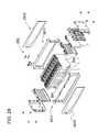
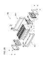
- Figs. 28 and 29 In order to solve the aforementioned problem, the applicant has developed power supply devices shown in Figs. 28 and 29 .
- temperature equalizing plates 2815 are fastened to bind bars 2811 that couple battery cells 1 of a battery block 283 to each other.
- temperature equalizing plates are formed integrally with bind bars 2911 that couple battery cells 1 of a battery block 293 to each other.
- the temperature equalizing plates are arranged on side surfaces of the battery block 283 or 293, and partially close the cooling gaps 284 or 294 between the battery cells 1.
- the opening area of the temperature equalizing plate is gradually changed so that the cooling gap 284 or 294 gets narrower particularly toward the upstream side into which cooling gas is blown.
- the amounts of blowing cooling gas are adjusted for battery cells one by one by the temperature equalizing plates so that the temperature difference among the battery cells 1 can be reduced.
- the bind bar since the bind bar is constructed as the temperature equalizing plate, the bind bars will be required to have different shapes and sizes depending on the sizes of battery cells and the number of side-by-side arranged battery cells. Accordingly, bind bars will be necessarily redesigned specially for battery blocks. As a result, there is a problem that the cost will be increased.
- a temperature equalizing plate 3015 separate from the bind bar is attached onto a side surface of a battery block 303.
- the temperature equalizing plate 3015 is formed of plastic with flexibility, and is fastened to an end plate 310 on the battery block 303 end surface.
- the shape of the temperature equalizing plate 3015 is designed to restrict cooling effect on battery cells. The restriction amount gets larger as closer to a battery cell on the upstream side of cooling gas. The restriction is achieved by closing cooling gaps 304 with the temperature equalizing plate 3015. The closing amount gets smaller along the flowing direction of cooling gas.
- the temperature equalizing plate 3015 serves as a baffle so that the amount of blowing cooling gas is regulated. As a result, the temperature difference among the battery cells 1 can be reduced.
- the temperature equalizing plate is constantly blown with the forcedly blowing cooling gas, the blowing cooling gas causes a free end of the temperature equalizing plate to fluster.
- the temperature equalizing plate produces noise.
- flustering movement may cause deterioration of the resin temperature equalizing plate in strength.
- Such deterioration may facilitate flustering movement.
- the power supply device is used as a vehicle power supply device, since the power supply device is subjected to vibrations, such deterioration will be accelerated.
- the temperature equalizing plate flusters the cooling gap may be insufficiently closed so that battery cells may be insufficiently uniformly cooled.
- the present invention is devised to further solve the above problems. It is a main object of the present invention is to provide a power supply device that can reduce temperature difference among battery cells and can suppress noise production, and a vehicle including the power supply device.
- a power supply device includes a battery block 3, coupling members 11, and a temperature equalizing plate 15.
- the battery block 3 includes a plurality of battery cells 1 arranged side by side.
- the cooling gaps 4 are formed for flowing cooling gas between battery cells 1.
- the coupling members 11 extend in the side-by-side arrangement direction of the battery cells 1, and couple the plurality of battery cells 1 to each other in the side-by-side arrangement.
- the temperature equalizing plate 15 is arranged on a side surface of the battery block 3, and at least partially closes openings of some of the cooling gaps 4 on the cooling gas inlet side of the cooling gaps 4. The cooling gas is blown from the side surface of the battery block 3 into the cooling gaps 4 so that the battery cells 1 are cooled.
- the temperature equalizing plate 15 covers the side surface of the battery block 3.
- the width of the temperature equalizing plate 15 varies so that the amounts of the cooling gas flowing into the cooling gaps 4 is reduced as the battery cells are located closer to the cooling gas upstream side.
- the cooling gas upstream side of the temperature equalizing plate 15 is fastened to the battery block 3.
- the temperature equalizing plate 15 includes attachment protrusions 37 that protrude from the cooling gas downstream side of the temperature equalizing plate 15.
- Protrusion insertion portions 39 are arranged at positions of the coupling members 11 corresponding to the attachment protrusions 37 on the side surface of the battery block 3 so that the attachment protrusions 37 can be inserted into the protrusion insertion portions 39.
- the temperature equalizing plate 15 When the attachment protrusions 37 of the temperature equalizing plate 15 are inserted in the protrusion insertion portions 39 of the coupling members 11, the temperature equalizing plate 15 is attached to the coupling members 11. According to this construction, it is possible to suppress that blowing cooling gas causes the free end of the temperature equalizing plate to fluster, and to suppress noise production. Also, according to this construction, the protrusion insertion portions protrude from the side surface of the battery block. In the case where a plurality of battery blocks are arranged with their side surfaces facing to each other, the protrusion insertion portions of the adjacent battery blocks come in contact with each other. Accordingly, the battery blocks are held from the side surfaces by their protrusion insertion portions. Therefore, it is possible to provide an effect that the battery blocks can be stably secured at increased mechanical strength.
- the temperature equalizing plate 15 has a recessed surface on the side opposed to the battery block 3.
- An elastic member 41 is arranged on the recessed surface. According to this construction, since the elastic member arranged on the temperature equalizing plate comes in contact with the battery block, it is possible suppress that vibration sound of the temperature equalizing plate when coming in contact with the battery block. Therefore, it is possible to ensure low noise.
- the width of the elastic member 41 gradually decreases along the side-by-side arrangement direction of the battery cells 1 of the battery block 3. According to this construction, since the area of the elastic member is changed in addition to the area of the temperature equalizing plate, it is possible to provide an effect that the temperature difference ⁇ T among battery cells can be further reduced.
- the temperature equalizing plate 15 is curved protruding toward the battery block 3. According to this construction, since the temperature equalizing plate can be in contact with the battery block side as tight as possible, it is possible to increase an effect for closing the some of the cooling gaps.
- the shape of the temperature equalizing plate 15 is an isosceles trapezoid. According to this construction, the temperature equalizing plate can gradually change the opening areas of cooling gaps.
- the temperature equalizing plate 15 is fastened only on the cooling gas inlet-side side surface of the both side surface of the battery block 3. According to this construction, the amount of cooling gas that flows into cooling gaps can be effectively suppressed on the inlet side. Therefore, even in the case where the number of temperature equalizing plates is reduced, it is possible to uniformly cool the battery cells.
- the coupling member 11 is a metal bind bar 11X that has a constant width and extends in the side-by-side arrangement direction of the battery cells 1.
- the attachment protrusion 37 protrudes along the extension direction of the bind bar 11X, and has a width equal to or narrower than the width of the bind bar 11X.
- the protrusion insertion portion 39 is formed by bending each of a pair of metal protrusions that protrude in the width direction of the bind bar 11X into a U shape as viewed in section. According to this construction, the protrusion insertion portion can be easily formed.
- the temperature equalizing plate 15 further includes protruding portions 38 that couple the attachment protrusions 37 to the temperature equalizing plate 15.
- the protruding portions 38 overlap one of the battery cells 1 of the battery block 3.
- the protruding portion is arranged at a position that does not overlap battery cells, that is, at a position where the protruding portion does not close cooling gaps. Accordingly, it is possible to avoid that the protruding portion interferes with the flow of the cooling gas into the cooling gaps. Therefore, it is possible to make full use of the capabilities of the temperature equalizing plate.
- a second protrusion insertion portion 39B is arranged at the symmetrical position to the protrusion insertion portion 39 with respect to the center of the coupling member 11 in the extension direction, and have the same shape as the protrusion insertion portion 39.
- end plates 10 are further included that hold the side-by-side arranged battery cells 1 so that the side-by-side arranged battery cells 1 are sandwiched between the end plates 10 from both the ends of the battery block 3.
- the temperature equalizing plate 15 includes an interlocking hook 33 on the side opposite to the attachment protrusions 37.
- the end plate 10 has an interlocking hole 34 that interlocks with the interlocking hook 33. When the interlocking hook 33 is interlocked with the interlocking hole 34, the cooling gas upstream side of the temperature equalizing plate 15 is fastened to the battery block 3. According to this construction, there is an advantage that the both ends of the temperature equalizing plate can be easily and reliably fastened to the battery block by snap-in structures.
- electrically-insulating separators 2 are further included that are sandwiched between battery cells 1 so that the cooling gaps 4 are formed in the battery block 3. According to this construction, the separators for insulating battery cells from each other can be used as spacers for forming the cooling gaps.
- the battery cells 1 are rectangular batteries. According to this construction, it is possible to uniformly cool the battery block that includes rectangular battery cells arranged side by side.
- a vehicle according to a fourteenth aspect of the present invention includes the aforementioned power supply device.
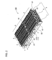
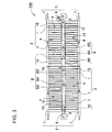
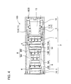
- Figs. 1 to 7 show a power supply device 100 according to an embodiment 1 of the present invention.
- Fig. 8 shows a power supply device 200 according to an embodiment 2 of the present invention.
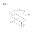
- Fig. 9 shows a power supply device 300 according to an embodiment 3 of the present invention.
- the illustrated power supply devices are suitable mainly for power supplies of electric vehicles such as hybrid cars that are driven by both an engine and an electric motor, and electric vehicles that are driven only by an electric motor.
- the power supply devices can be used for vehicles other than hybrid cars or electric vehicles, and can be also used for applications other than electric vehicle that require high power.
- Each of the battery blocks 3 includes of a plurality of battery cells 1 of rectangular batteries.
- the battery cells 1 are arranged side by side to form cooling gaps 4 between the battery cells 1.
- the blower mechanism 9 forcedly blows cooling gas for cooling the battery cells 1 of the battery block 3.
- separators 2 are interposed between the battery cells 1, which are arranged side by side.
- the separator 2 has a shape that can define the cooling gaps 4 between the battery cells 1 as shown in Fig. 7 .
- the illustrated separator 2 holds the battery cells 1 by a fit-in structure.
- the battery cells 1 are fitted in the separator 2 on the both surfaces of the separator 2.
- adjacent battery cells 1 are arranged side by side without positional deviation by the separator 2 that holds the battery cells 1 by using the fit-in structure.
- the battery cells 1 of rectangular batteries 1 are lithium-ion rechargeable batteries. However, the battery cells may be nickel-hydrogen batteries or nickel-cadmium batteries.
- the battery cell 1 shown in Fig. 7 has a rectangular shape with a predetermined thickness, and includes positive/negative electrode terminals 13 and an opening 1A for a safety valve. The positive/negative electrode terminals 13 protrude from the ends of the upper surface of the battery cell 1. The opening 1A is located in the middle of the upper surface of the battery cell 1.
- the adjacent electrode terminals 13 of the side-by-side arranged battery cells 1 are serially connected to each other by connectors (not shown).
- one of the positive and negative electrode terminals 13 is laid on and thus coupled to the other of the positive and negative electrode terminals 13 so that adjacent battery cells 1 are serially connected to each other.
- the positive and negative electrode terminals 13 can be serially connected to each other by busbars (not shown).
- busbars not shown.
- the output voltage of the power supply device can be high, and as a result the power supply device can provide high power.
- adjacent battery cells may be connected in parallel to each other.
- the battery cell 1 includes a metal exterior can.
- the separator 2 is made of an electrically-insulating material, and interposed between the battery cells 1.
- the exterior container of the battery cell may be formed of an electrically-insulating material such as plastic.
- the separator since the electrically-insulating exterior containers of the battery cells are not necessarily arranged side by side, the separator may be formed of metal.
- the separator 2 is formed of an electrically-insulating material such as plastic, and electrically insulates the adjacent battery cells 1 from each other.
- the separator 2 is inserted between the battery cells 1 for electrically insulating the battery cells from each other as shown in a perspective view of Fig. 7 .
- the separator 2 serves as a spacer for forming the cooling gap 4 between battery cells 1. Since the battery block 3 includes the separators 2, which are thus arranged side by side and interposed between the battery cells 1, the cooling gaps 4 are formed between the battery cells 1 as shown in a side view of Fig. 4 so that cooling gas flows through the cooling gaps 4 and cools the battery cells 1.
- the cooling gas can be outside air, air heat-exchanged with coolant, coolant or the like.
- the separator 2 shown in Fig. 7 has grooves 2A on its surfaces that face the battery cells 1.
- the grooves 2A extend to the both edges of the separator 2.
- the cooling gaps 4 are thus formed between the battery cells 1.
- the grooves 2A are arranged in parallel to each other at a predetermined interval.
- the grooves 2A are formed on the both surfaces of the separator 2 shown in Fig. 7 .
- the cooling gaps 4 are formed between each of adjacent battery cells 1 and the separator 2.
- the thus-configured power supply device has a feature that the battery cells 1 on the both sides of the separator can be effectively cooled via the cooling gaps 4, which are formed on the both sides of the separator 2.
- the grooves may be formed only on one side of the separator.
- the cooling gaps are formed between the battery cell and the separator.
- the illustrated cooling gap 4 extends in the horizontal direction, and opens toward the left and right sides of the battery block 3.
- the separator 2 shown in Fig. 7 has cut-out portions 2B on both edge parts. The width between surfaces of adjacent battery cells 1 opposed to each other can be wide in the cut-out portion 2B on both edge parts of the separator 2 so that cooling gas flow resistance can be small. For this reason, cooling gas can smoothly pass from the cut-out portion 2B through the cooling gaps 4 between the separator 2 and the battery cells 1. Therefore, the battery cells 1 can be effectively cooled. As discussed above, air is forcedly blown through the cooling gaps 4, and efficiently and directly cools the exterior containers of the battery cells 1.
- the thus-configured power supply device has a feature in that thermal runaway of the battery cell 1 can be effectively prevented and the battery cells 1 can be efficiently cooled.
- a pair of end plates 10 are arranged on opposed ends of the battery block 3.
- the pair of end plates 10 are coupled by coupling members 11 so that the side-by-side arranged battery cells 1 and the separators 2 are secured between the end plates 10.
- the end plates 10 have a rectangular shape corresponding to the external shape of the battery cell 1.
- the both ends of the coupling member 11 are bent inward as shown in Fig. 6 .
- These bent portions 11d are secured to the end plates 10 by fastening screws 12.
- the bent portions of the coupling members may extend so as to surround the entire length of each of the end plates, and may be secured to the end plates by the fastening screws. Alternatively, threaded holes may be formed on the side surface of the end plate.
- the coupling members are secured to the end plates by fastening screws that penetrate the coupling members.
- these coupling members to be secured to the outer side surfaces of the end plates do not have the bent portions, but are farmed in a straight shape and secured to the end plates.
- the end plate 10 shown in Fig. 6 is formed of metal.
- the end plate 10 includes reinforcing ribs 10A that are integrally formed with the outside of the end plate 10 whereby reinforcing the end plate 10.
- the metal end plate 10 has sufficient strength, and can bear coupling torque of the fastening screws 12.
- the coupling recessed portions 10a are formed on the outside surface of the end plate 10, and receive the bent portions 11d of the coupling members 11.
- the end plate 10 shown in Fig. 6 has four coupling recessed portions 10a on the outside surface at the four-corner parts.
- the coupling holes 10a are threaded holes.
- the fastening screws 12 pass through the coupling members 11, and are screwed into the threaded holes.
- the coupling members 11 can be secured to the end plates 10.
- the end plate is not limited to metal.
- the end plate may be formed of resin, which is advantageous from the viewpoint of ease of molding, electrically insulation property, and the like.
- Bind bars 11 X corresponds to the coupling members 11.
- the bind bars 11X have a predetermined vertical width.
- the bind bar 11X as the coupling member 11 is a metal plate with a predetermined vertical width.
- the both ends of the bind bars 11X as the coupling members 11 are secured to the four corner parts of the end plates 10.
- the bind bars 11X are arranged in parallel to each other on the upper and lower parts of the both sides of the battery cells 1. In the battery block 3 with the bind bars 11X being secured to the upper and lower part of both sides, as shown in Fig. 4 , some of the cooling gaps 4 arranged between the battery cells 1 in the upper and lower parts of will be closed by the bind bars 11X.
- the cooling gaps 4 have openings 14 that open on the both sides of the battery cells 1.
- the entire openings 14 can be divided into closed portions 14A and exposed portions 14B.
- the closed portions 14A are located on the upper and lower parts, and are closed by the bind bars 11X.
- the openings 14 in the exposed portion 14B are not closed by the bind bars 11 X.
- the exposed portion 14B is formed between the closed portions 14A on the upper and lower parts, and communicates with an air duct 5.
- the exposed portion 14B communicates with an inlet duct 6.
- the cooling gas is forcedly blown into the exposed portion 14B through the inlet duct 6.
- the bind bars 11 X are arranged on the upper and lower parts of the both side surfaces of the battery block 3. As a result, the entire cooling gaps 4 can be divided into the upper and lower closed portions 14A, and the exposed portion 14B. An exposed portion 14B on one side communicates with the inlet duct 6, while an exposed portion 14B on the other side communicates with the outlet duct 7. Thus, the battery cells 1 are cooled by the cooling gas.
- the thus-configured battery blocks 3 are arranged in two rows as shown in Figs. 2 , 3 and 5 .
- the air ducts 5 are arranged in a part between the two rows of battery blocks 3, and parts outside the two rows of battery blocks 3.
- the inlet duct 6 is arranged in the part between the two rows of battery blocks 3, and communicates with cooling gaps 4.
- the outlet ducts 7 are arranged in parts outside the two rows of battery blocks 3 so that the cooling gaps 4 are arranged in parallel to each other between each of the outlet ducts 7 and the inlet duct 6 and communicate with each other.
- this power supply device as shown by arrows in Figs.
- cooling gas is forcedly blown from the inlet duct 6 toward the outlet ducts 7 by the blower mechanisms 9 to cool the battery cells 1.
- the cooling gas is forcedly blown from the inlet duct 6 toward the outlet ducts 7, and is then branched from the inlet duct 6.
- the cooling gas flows in the cooling gaps 4 to cool the battery cells 1.
- the cooling gas flows merge into the outlet duct 7. After that, the merging cooling gas is discharged.
- the aforementioned power supply device includes the inlet duct arranged between the battery blocks arranged in parallel to each other, and the outlet ducts arranged outside the battery blocks so that cooling gas is blown from the central part to the outside parts of the power supply device.
- the construction for blowing cooling gas to the battery block is not limited to this construction.
- the inlet ducts can be arranged outside the battery blocks, while outlet duct can be arranged between the battery blocks so that cooling gas is blown from the outside parts to the central part of the power supply device.
- Fig. 8 shows this type of power supply device as an embodiment 2. In the power supply device 200 according to the embodiment 2 shown in Fig.
- inlet ducts 56 are arranged in parts outside the two rows of battery blocks 3, and an outlet duct 57 is arranged in the part between the two rows of battery blocks 3 and communicates with cooling gaps 4.
- cooling gas is forcedly blown from the inlet ducts 56 arranged in parts outside the power supply device 200 toward the outlet duct 57 arranged in the central part of the power supply device 200 by the blower mechanism 9 to cool the battery cells 1.
- the cooling gas is forcedly blown from the inlet ducts 56 arranged outside, and then cooling gas flows pass through the cooling gaps 4 to cool the battery cells 1.
- cooling gas flows merge into the outlet duct 57 arranged in the central part of the power supply device. After that, the merging cooling gas is discharged.
- Each of the power supply devices shown Figs. 1 to 3 and Fig. 8 includes four battery blocks 3.
- the four battery blocks 3 are arranged in two columns and two rows.
- Two battery blocks 3 that compose each column are arranged in parallel to each other in two rows so that the air ducts 5 or 55 are arranged in the central part and the outside parts of the power supply device.
- two sets of the thus-arranged parallel two battery blocks 3 are arranged in two columns. That is, as shown in Fig. 5 , a center barrier wall 19 is arranged between the two sets of battery blocks 3 that compose adjacent columns so that two sets of air ducts 5 or 55, which are arranged in the central part and the outside parts of the power supply device in two columns of battery blocks 3, are cut off from each other.
- cooling gas is provided to the battery blocks 3 in each column through the separated inlet ducts 6 or 56, as shown in Fig. 3 and Fig. 8 , and the cooling gas is forcedly blown into the cooling gaps 4 and is then discharged through the separates outlet ducts 7 or 57.
- cooling gas is forcedly blown from the inlet ducts 6 and 56 to the outlet ducts 7 and 57 in opposite directions, and cools the battery cells 1.
- the aforementioned power supply devices include four battery blocks 3, which are arranged in two columns and two rows. Two battery blocks 3 are arranged in parallel to each other in each of two rows. However, the power supply device can include only two battery blocks that are arranged in parallel to each other in two rows. That is, battery blocks can be arranged in one column and two rows. In this illustrated power supply devices, cooling gas can be forcedly blown between the inlet and outlet ducts in either direction, and can cool the battery cells 1. In the case where four battery blocks arranged in two columns and two rows, the center barrier wall may not be provided between the battery blocks in two columns and the between air ducts in two columns but a set of two battery blocks adjacent to each other in the row direction may be aligned in straight.
- two sets of the thus-aligned battery blocks may be arranged in parallel to each other in two rows so that the air ducts are arranged inside and outside.
- the inlet duct(s) can be one of the fun duct arranged inside and a pair of the fun ducts arranged outside in the battery blocks, which are arranged in two columns and two rows, while the outlet duct(s) can be the other so that cooling gas forcedly blown from the inlet duct(s) is led to the cooling gaps and is discharged through the outlet duct(s).
- cooling gas can be forcedly blown between the inlet and outlet ducts in either direction, and can cool the battery cells.
- the area of the air ducts 5 arranged between battery blocks 3 arranged in parallel to each other in two rows is twice the area of the air ducts 5 arranged outside the battery blocks 3 in two rows.
- the reason is that cooling gas forcedly blown through the inlet duct 6 arranged between two battery blocks 3 is branched into two flows, and the branched cooling gas flows are discharged through the outlet ducts 7 arranged on the both sides in the power supply device shown in Figs. 1 to 3 .
- cooling gas forcedly blown through the inlet ducts 56 arranged on the both sides is discharged through the outlet ducts 57 arranged between two battery blocks 3 in the power supply device shown in Fig. 8 . That is, in the power supply device shown in Figs.
- the inlet duct 6 passes cooling gas twice as much as the outlet ducts 7 on the both sides, the inlet duct 6 is required to have a cross-sectional area twice as large as the outlet ducts 7 in order to reduce pressure loss.
- the width of the inlet duct 6 is designed twice as large as the width of the outlet duct 7. Also, in the power supply device shown in Fig.
- the outlet duct 57 arranged in the central part of the power supply device passes cooling gas twice as much as the inlet ducts 56 on the both sides, the outlet duct 57 is required to have a cross-sectional area twice as large as the inlet ducts 57 in order to reduce pressure loss. Also, in order that the outlet duct 57 as the air duct 55 arranged in the central part of the power supply device can have a larger cross-sectional area, the width of the outlet duct 57 is designed twice as large as the width of the inlet duct 56.
- the aforementioned power supply device has been described that includes the battery blocks 3, which are arranged in parallel to each other in two rows, and the air ducts 5 and 55, which are arranged in a part between the two rows of battery blocks 3 and in parts outside the two rows of battery blocks 3.
- the power supply device can be composed of one row of battery blocks.
- two air ducts 75 are arranged on the both sides of one row of battery blocks 3.
- One of the two air ducts 75 serves as an inlet duct 76, while the other of the two air ducts 75 serves as an outlet duct 77.
- this power supply device 300 as shown by arrows in Fig.
- cooling gas is forcedly blown from the inlet duct 76 toward the outlet ducts 77 by the blower mechanism 9 to cool the battery cells 1.
- the cooling gas is forcedly blown from the inlet ducts 76, and then cooling gas flows pass through the cooling gaps 4 to cool the battery cells 1. After cooling the battery cells 1, the cooling gas flows merge into the outlet duct 77. After that, the merging cooling gas is discharged.
- the inlet and outlet ducts 76 and 77 arranged on the both sides are designed to have the same cross-sectional area, that is, the widths of the inlet and outlet ducts 76 and 77 are dimensioned equal to each other.
- a temperature equalizing plate 15 can be attached onto a part of a side surface of the battery block 3.
- the temperature equalizing plate 15 is arranged so as to partially close some of the cooling gaps 4 so that the limitation amount on battery cell 1 cooling performance gets larger toward the upstream side.
- the temperature equalizing plate interferes with cooling gas flowing into the some of the cooling gaps 4.
- the closing amount of cooling gap 4 by the temperature equalizing plate gets smaller toward the cooling gas flowing direction. According this construction, the temperature difference among the battery cells 1 can be reduced.
- the battery block 3 shown in Figs. 4 to 6 is provided with a temperature equalizing plate 15 the vertical width of which gets larger toward the end of the battery block 3, i.e., toward the upstream side.
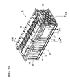
- Fig. 10 is a perspective view showing the battery block 3 with the temperature equalizing plate 15 being fastened to the battery block 3.
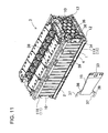
- Fig. 11 is an exploded perspective view showing the battery block with the temperature equalizing plate being removed from the battery block shown in Fig. 10 .
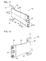
- Fig. 12 is a perspective view showing the temperature equalizing plate 15 shown in Fig. 11 .
- Fig. 13 is a perspective view showing the temperature equalizing plate 15 shown in Fig. 12 as viewed from the back side.
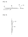
- Fig. 14 is a traverse sectional view of the temperature equalizing plate 15 shown in Fig. 12 taken along the line XIV-XIV. Fig.
- Fig. 15 is a longitudinal sectional view of the temperature equalizing plate 15 shown in Fig. 12 taken along the line XV-XV.
- Fig. 16 is a partially horizontally sectional perspective view of the battery block shown in Fig. 10 taken along the line XVI-XVI.
- Fig. 17 is a vertically sectional perspective view of the battery block shown in Fig. 10 taken along the line XVII-XVII.
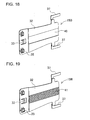
- Fig. 18 is a perspective view showing a temperature equalizing plate 15B according to a modified embodiment as viewed from the back surface side.
- Fig. 19 is a perspective view showing the temperature equalizing plate 15B shown in Fig. 18 with an elastic member 41 being secured onto the temperature equalizing plate 15B.
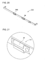
- FIG. 20 is a perspective view showing a bind bar 11X.
- Fig. 21 is an enlarged perspective view showing a protrusion insertion portion 39 of the bind bar 11X shown in Fig. 20 .
- Fig. 22 is a perspective view showing a bind bar 11Y according to a modified embodiment.
- Fig. 23 is an enlarged perspective view showing a protrusion insertion portion 39 of the bind bar 11Y shown in Fig. 22 .
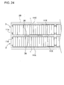
- Fig. 24 is a plan view showing battery blocks 3 that are arranged in parallel to each other with protrusion insertion portions 39 of bind bars 11X contacting each other.
- the temperature equalizing plate 15 is arranged on the cooling gas flowing path, and serves as a baffle for interfering with the cooling gas flow.
- the temperature equalizing plate 15 includes a main plate portion 32 that has an isosceles trapezoid as shown in the perspective view of Figs. 12 and 13 .
- An interlocking hook 33 is arranged at the center of the wider width part of the main plate portion 32.
- attachment protrusions 37 are arranged at the upper and lower ends of the narrower width part of the main plate portion 32.
- the temperature equalizing plate 15 is arranged in an upstream side part of the battery block. According to this arrangement, since the temperature equalizing plate 15 partially closes the some of the cooling gaps 4 whereby limiting the cooling gas flowing rate, it is possible to suppress that the some of the battery cells on the upstream side are cooled too much by the cooling gas so that the temperatures of the battery cells becomes lower and the temperature difference between the some of the battery cells and the other battery cells becomes larger. It should be noted that the temperature equalizing plate 15 does not necessarily close all of the battery cells on the side surface of the battery block. The temperature equalizing plate 15 is only required to reduce the temperature difference among the battery cells. From this viewpoint, the temperature equalizing plate has a size capable of covering some of the battery cells 1 on the upstream side as shown in Fig. 10 , etc.
- the temperature equalizing plate 15 according to the embodiment shown in Fig. 10 is fastened to the end plate 10.
- the interlocking hook 33 is arranged in the wider width part on the upstream side of the main plate portion 32.
- the interlocking hook 33 is arranged at substantially the center in the width direction and has a hook shape that has a pawl protruding toward the battery block 3.
- an interlocking hole 34 is formed in the end plate 10 as shown in Fig. 11 , and can interlock with the interlocking hook 33.
- Bosses 35 are arranged protruding from the upper and lower sides of the temperature equalizing plate 15 above and below the interlocking hook 33, and can come in contact with and inserted into the end plate 10.
- boss receiving holes 36 are formed in the end plate 10. The bosses 35 are inserted into the boss receiving holes 36.
- the temperature equalizing plate 15 can be formed of heat-resistant resin or from a metal plate.
- the temperature equalizing plate according to this embodiment is formed of heat-resistant plastic. It is preferable that the interlocking hook 33, the bosses 35, and the attachment protrusions 37 be integrally formed. In this case, the temperature equalizing plate 15 can be inexpensively manufactured. In the case where the temperature equalizing plate 15 can be inexpensively manufactured, the temperature equalizing plate 15 can be flexibly used for various types of power supply devices. That is, if a temperature equalizing plate 2815 is fastened to the bind bar 2811 as shown in Fig. 28 , or if a bind bar 2911 also serves as the temperature equalizing plate as shown in Fig.
- the temperature equalizing plate when the shape of the battery block is changed by changing the number of battery cells of the battery block depending on required voltages, it is necessary to redesign the temperature equalizing plate. As a result, the cost of the temperature equalizing plate will be increased. Contrary to this, in the case where the temperature equalizing plate is formed as a separated member from the bind bar, the bind bar can be easily designed so that the shape of the battery block can be easily changed at low cost. In addition, the temperature equalizing plate can have a simple attachment structure and can be easily attached. In this case, the temperature equalizing plate is advantageous in terms of manufacturing cost reduction.
- the temperature equalizing plate is fastened to the battery block 3 only on cooling gas flowing-in-side side surface of the both side surfaces of the battery block 3.
- the temperature equalizing plate 15 is fastened only on the flowing-in side, even if the temperature equalizing plates are not fastened on the both side surfaces, cooling gas can sufficiently be suppressed. Accordingly, the number of temperature equalizing plates can be reduced. Therefore, it is possible to simplify the construction of the power supply device, and to reduce the cost of the power supply device.
- the downstream side part of the temperature equalizing plate 15 is fastened to the bind bars 11X.
- the attachment protrusions 37 are arranged in the main plate portion 32 of the temperature equalizing plate 15 on the side opposite to the interlocking hook 33, in other words, on the cooling gas downstream side.
- the temperature equalizing plate 15 includes protruding portions 38 that protrude in the vertical width direction from the upper and lower sides of the main plate portion 32, and the attachment protrusions 37 that protrude from the ends of the protruding portions 38 in the direction perpendicular to the protruding direction of the protruding portions 38, in other word, in the longitudinal direction of the main plate portion 32.
- the attachment protrusions 37 extend in the longitudinal direction of the bind bars 11X.
- the temperature equalizing plate 15 can be securely fastened to the battery block 3. According to this construction, it is possible to eliminate efforts to screw screws into screw holes for fastening the temperature equalizing plate to the battery block, for example. Therefore, the temperature equalizing plate can be simply fastened to the battery block in the assembling of the power supply device.
- the protruding portion 38 is formed in a stepped shape so that the attachment protrusion 37 on the end of the protruding portion 38 is spaced away from the flat surface of the main plate portion 32 as shown in the perspective view of Figs. 12 and 13 , and the cross-sectional view of Fig. 17 .
- the spacing distance between the main plate portion 32 and the attachment protrusion 37, in other words, the step height of the protruding portion 38 is designed depending on the height of the bind bar 11X from the side surface of the battery block 3. According to this construction, when the attachment protrusion 37 is inserted into the protrusion insertion portion 39 (discussed in detail later) of the bind bar 11X, the main plate portion 32 can be in contact with the side surface of the battery block 3.
- the main plate portion 32 is curved in a concave shape as viewed from the lateral side as shown in the cross-sectional views of Figs. 17 and 15 . According to this construction, the main plate portion 32 can surely come in tight contact with the side surface of the battery block 3. Therefore, cooling gaps 4 can surely be closed.
- the elastic member 41 be interposed between the temperature equalizing plate 15 and the battery block 3.
- a recessed portion 40 is formed in the vertically central part along the longitudinal direction of the main plate portion 32 of the temperature equalizing plate 15B.
- the elastic member 41 is held in the recessed portion 40.
- the elastic member 41 is suitably formed of a rubber sheet. Since the elastic member 41 is interposed between the temperature equalizing plate and the battery block, the temperature equalizing plate 15B can be in tight contact with the battery block 3 so that the cooling gaps 4 can be surely closed.
- the elastic member 41 can be fastened to the recessed portion 40 of the main plate portion 32 with an adhesive.
- the elastic member can be fastened the temperature equalizing plate by insertion molding.
- the temperature equalizing plate may be formed of an elastic material.
- the area of the elastic member 41 can be gradually reduced along the side-by-side arrangement direction of the battery cells 1 of the battery block 3. According to this construction, since the area of the elastic member 41 is changed as the area of the main plate portion 32 is changed, it is possible to further reduce the temperature difference ⁇ T among the battery cells.
- the protrusion insertion portion 39 is arranged in the bind bar 11 X.
- the attachment protrusion 37 is inserted into the protrusion insertion portion 39.
- the protrusion insertion portion 39 opens toward longitudinal ends of the bind bar 11X, and has an inner height that can hold the attachment protrusion 37.
- the width of the attachment protrusion 37 is preferably substantially same as or barrower than the width of the bind bar 11 X. According to this construction, when the attachment protrusion 37 is inserted into the protrusion insertion portion 39, the attachment protrusion 37 overlaps the bind bar 11X. Therefore, it is possible to suppress undesired protrusion of the attachment protrusion 37 toward the side surface of the battery block.
- the temperature equalizing plate 15 can be fastened to the bind bars 11X almost without changing the area of the cooling gap 4 closed by the temperature equalizing plate 15.
- the size of the main plate portion 32 of the temperature equalizing plate 15 is designed so as to change the closed amounts of the cooling gaps between battery cells one by one, it can be said that protrusion or deformation of the protrusion insertion portion toward the side surface of the battery block 3 is preferably minimized.
- the protrusion insertion portions 39 are attached to the bind bars 11X so as to overlap the bind bars 11X as discussed above, the protrusion amounts of the protrusion insertion portions 39 toward the side surface of the battery block 3 are minimized to an amount not greater than necessary, that is, to the protruding portions 38 that couple the main plate portion 32 to the attachment protrusions 37. As a result, it is possible to suppress that cooling gaps are affected by the protrusion insertion portions 39.
- the protruding portions 38 be designed to be arranged at positions of the main plate portion 32 so that the protruding portion 38 overlaps the battery cell 1, in other words, at positions where the protruding portions 38 do not close the cooling gap 4 as shown in Fig. 10 . According to this construction, it is possible avoid that the protruding portions 38 close the cooling gap. As a result, the temperature equalizing plate 15 can serve essentially to gradually reduce the closed amount of the cooling gaps between the battery cells one by one along the cooling gas flowing direction, in other words, to gradually increase the rate of cooling gas flowing into the cooling gaps between the battery cells one by one along the cooling gas flowing direction.
- the attachment protrusion 37 extends along the longitudinal direction of the bind bar 11X, there is an advantage that the attachment protrusion 37 can be long. That is, if the attachment protrusion 37 extends in the direction perpendicular to the bind bar 11X as shown in Fig. 30 , the length of the attachment protrusion 37 must be short. Accordingly, the contact area of the attachment protrusion with the protrusion insertion portion 39 becomes small. As a result, the attachment strength between the attachment protrusion and the protrusion insertion portion becomes relatively low. Contrary to this, since the attachment protrusion 37 is arranged at the position where the attachment protrusion 37 overlaps the bind bar 11X, the length of the attachment protrusion 37 can be sufficiently increased.
- the length of the protrusion insertion portion 39 can be increased.
- the contact resistance between the attachment protrusion and the protrusion insertion portion can be increased. Accordingly, the temperature equalizing plate 15 can be stably held for a long time. Therefore, it is possible to improve the reliability of the power supply device.
- the length of the protrusion insertion portion 39 is designed in accordance with the length of the attachment protrusion 37.
- the protrusion insertion portion 39 preferably has a depth that allows at least a half length of the attachment protrusion 37 to be inserted into the protrusion insertion portion 39.
- the sectionally C-shape protrusion insertion portion 39 is formed by bending each of the ends of a metal strip into a U shape as viewed in section.
- the protrusion insertion portion 39 has a slit that extends along the center line of the protrusion insertion portion. Accordingly, it is easy to deform the protrusion insertion portion 39. Therefore, it is easy to adjust the inner height of the protrusion insertion portion 39.
- the protrusion insertion portion 39 is formed from a metal strip that is a separated member from the separate bind bar 11X and is fixed onto the separate bind bar 11X by welding or the like in the case of Fig. 21
- the protrusion insertion portion may be formed integrally with the bind bar.
- a metal plate can be used that includes protruding parts that protrude upward and downward from the central parts of the metal plate.
- the protrusion insertion portion can be formed by bending the protruding parts.
- the bind bar 11X is formed of metal such as aluminum. End parts of the bind bar 11X are bent that have a certain length, and serve as parts to be fastened to the end plate 10.
- the protrusion insertion portion 39 is not limited to the aforementioned structures. Other structures can be suitably used into which the attachment protrusion 37 can be inserted.
- a bind bar 11Y according to a modified embodiment shown in Figs. 22 and 23 , one portion to be bent is formed integrally with a bar part, and protrudes from only one edge part. This one portion is bent, and the free end of the one portion is fixed to the bar part by welding.
- a protrusion insertion portion 39Y is formed. Since this protrusion insertion portion 39Y can be formed without using a separated member from the bind bar, the bind bar can be inexpensively manufactured.
- the bind bar 11X has a symmetrical shape.
- the bind bar 11X according to the embodiment shown in Fig. 20 , etc. includes two protrusion insertion portions 39 that are arranged at the symmetrical positions with respect to the center in the longitudinal direction of the bind bar 11X.
- this bind bar 11X one of the protrusion insertion portion 39 (on right side in Fig. 20 ) is used, but the other protrusion insertion portion 39 (second protrusion insertion portion 39B on the left side in Fig. 20 ) is not used.
- the bind bar 11X since the bind bar 11X has a symmetrical shape with respect to the horizontal and vertical lines, the bind bar 11X can be used irrespective of orientation of the bind bar 11X. Accordingly, the orientation mistake can be eliminated when the power supply device is assembled. Therefore, the assembling efficiency can be improved.
- the battery blocks 3 can be firmly held at the contact parts between the metal members.
- the protrusion insertion portions 39 are pressed toward each other, and are slightly deformed, the inner height of the protrusion insertion portions 39 will be reduced.
- the attachment protrusion 37 inserted into the deformed protrusion insertion portion 39 can be more reliably fastened to the bind bar so that the temperature equalizing plate 15 is prevented from being detached from the bind bar.
- the temperature equalizing plate 15 according to the foregoing embodiment is fastened to the battery block 3 by using a fit-in structure.
- the fit-in structure can eliminate screwing and welding efforts, etc., and fastens the temperature equalizing plate to the battery block in a snap-in manner. Therefore, the fit-in structure can provided excellent workability.
- the attachment structure of the temperature equalizing plate according to the present invention is not limited to the fit-in structure.
- the temperature equalizing plate can be fastened to the surfaces of the bind bars 11X by screws, an adhesive, a welding method or the like depending on required strength and reliability.
- the fit-in structure used in the present invention is not limited to the aforementioned construction. Any existing fit-in mechanisms can be suitably used.
- Temperature equalizing walls 8 and 58 are arranged in the inlet ducts 6, 56 and 76 to reduce the temperature difference among the battery cells 1.
- the temperature equalizing walls 8 and 58 have an elongated shape. Their entire length in the cooling gas flowing direction is longer than their width.
- one end part on the upstream side is tapered to get thinner toward the tip end.
- the other end part on the downstream side also gets thinner toward the tip end. Accordingly, it is possible to suppress that the cooling gas flow become turbulent. As a result, cooling gas can smoothly flow.
- a turbulent flow in the inlet ducts 6 and 56 and 76 may increase pressure loss. For this reason, in the case where the both end parts of the temperature equalizing walls 8 and 58 on the upstream and downstream sides get thinner toward the tip ends, it is possible to reduce pressure loss caused by turbulent flow.
- the end parts on the upstream and the downstream sides are inclined so that the vertical width of the end parts gets smaller toward the tip ends.
- the entire shape of the temperature equalizing walls 8 and 58 is a trapezoid the center part of which is high.
- the temperature equalizing walls 8 and 58 are arranged at opposed upper and lower positions in the inlet ducts 6, 56 and 76.
- the end parts are inclined downward toward the tip ends.
- the end parts are inclined upward toward the tip ends.
- the temperature equalizing walls 8 and 58 have a trapezoidal shape as a whole.
- the temperature difference among the battery cells can be reduced by the temperature equalizing walls 8 and 58 with low height, i.e., small vertical width.
- the temperature equalizing walls are not necessarily arranged at the upper and lower positions in the inlet duct.
- the temperature equalizing wall may be arranged only at the upper position or at the lower position in the inlet duct.
- the temperature equalizing walls 8 and 58 have tapered portions 8A and 58A the horizontal width of which gets smaller toward the top end edges of the temperature equalizing walls 8 and 58.
- the interval between the temperature equalizing walls 8 and 58 and the surface of the battery block 3 gets larger toward the top end edges of the temperature equalizing walls 8 and 58.
- the horizontal width gradually decreases toward the top side. Accordingly, the interval between the temperature equalizing walls 8 and 58 and the surface of the battery block 3 gradually increases toward the top side.
- the horizontal width gradually decreases toward the bottom side.
- the interval between the temperature equalizing walls 8 and 58 and the surface of the battery block 3 gradually increases toward the bottom side.
- the tapered portions 8A and 58A are not entirely formed.
- the temperature equalizing walls 8 and 58 include upper and lower parts of the taper portions 8A and 58A, and wide portions 8B and 58B.
- the wide portions 8B and 58B are arranged on the lower side, and the tapered portions 8A and 58A are arranged on the upper side.
- the wide portions 8B and 58B are arranged on the upper side, and the tapered portions 8A and 58A are arranged on the lower side.
- the wide portions 8B and 58B are shaped without horizontal width variation or with their horizontal width being changed in the vertical direction at an inclination smaller than the taper portions 8A and 58A.
- the wide portions 8B and 58B have vertical or nearly vertical side surfaces.
- the inlet duct 6 is arranged between the two rows of battery blocks 3.
- the temperature equalizing wall 8 is arranged in this inlet duct 6.
- the both surfaces of the tapered portion 8A of the temperature equalizing wall 8 are inclined at the same inclination angle ( ⁇ ).
- ⁇ inclination angle
- the intervals between the temperature equalizing wall 8, and the opposed surfaces of the battery blocks 3 are the same.
- the battery cells 1 of the battery blocks 3 on the both sides can be evenly cooled.
- the inlet ducts 56 are arranged outside the two rows of battery blocks 3.
- the temperature equalizing walls 58 are arranged in these inlet ducts 56.
- the tapered portion 58A of the temperature equalizing wall 58 has an inclined surface as the inside surface opposed to the surface of the battery block 3, and a vertical surface as the outside surface.
- the inclination angles ( ⁇ ) of the temperature equalizing walls 58 are the same that are opposed to each other and arranged in the inlet ducts 56 located on both the outsides of the two rows of the battery blocks 3.
- the intervals between the temperature equalizing walls 58 and the surfaces of the battery blocks 3 are symmetrical with respect to a line. The reason is that the battery cells 1 of the two columns of battery blocks 3 can be evenly cooled.
- the inclination angle ( ⁇ ) of the taper portions 8A and 58A with respect to the horizontal plane can be obtained from the horizontal width of the wide portions 8B and 58B, and the height of the tapered portions 8A and 58A.
- the tapered portion can be high when inclination angle ( ⁇ ) is large and the horizontal width of the wide portion is large.
- the tapered portion can be low when inclination angle ( ⁇ ) is small and the horizontal width of the wide portion is small.
- the length in the cooling gas flowing direction and the height of the tapered portions 8A and 58A are adjusted to values that can minimize the temperature difference among the battery cells 1.
- the temperature of a battery cell arranged on the downstream side in the cooling gas flowing direction will be higher than a battery cell 1 on the upstream side.
- the temperature equalizing walls 8 and 58 are arranged on the downstream side in the inlet ducts 6, 56, and 76.
- the length of the cooling gas flowing direction and the height of the tapered portions 8A and 58A are adjusted so as to further reduce the temperature difference among a half of battery cells that are arranged on the downstream side.
- the temperature difference occurs between a half of the whole battery cells (i.e., nine battery cells) arranged on the upstream side and another half of the battery cells arranged on the downstream side.
- the temperature of the nine battery cells arranged on the downstream side will be high, and as a result the temperature difference will be also large.
- battery cells 1 that are arranged on the inlet and outlet sides of the inlet ducts 6, 56 and 76 their temperature will be lower. The reason is that the end plates 10 on the both sides cool these battery cells 1.
- the temperature of a battery cell arranged on the downstream side will be the highest.
- the temperature of a fourteenth battery cell arranged in the center of the nine battery cells will be the highest.
- the temperature of the battery cells will get lower as closer to the upstream and downstream side relative to the battery cell arranged in the center of the downstream side battery cells.
- the temperature of the battery cell arranged to the both ends of the downstream side battery cells i.e., tenth and eighteenth battery cells
- the lowest temperature of a battery cell among battery cells on the upstream side will be 23°C.
- the temperature equalizing walls 8 and 58 are arranged on the downstream side of the inlet ducts 6, 56 and 76.
- the length of the cooling gas flowing direction and the height of the tapered portions 8A and 58A are adjusted so as to reduce the temperatures of, and the temperature difference among the battery cells 1 that are arranged on the downstream side.
- the temperature equalizing walls 8 and 58 are arranged in the inlet ducts 6, 56 and 76, and allow forcedly-blown cooling gas to more efficiently flow into the cooling gaps 4 whereby reducing the temperature of a battery cell 1 that is likely to increase in temperature.
- the wide portions 8B and 58B of the temperature equalizing walls 8 and 58 are arranged at positions facing the bind bars 11X of the battery block 3, and the tapered portions 8A and 58A of the temperature equalizing walls 8 and 58 are arranged at positions facing the exposed portion 14B of the battery block 3. That is, the wide portions 8B and 58B are arranged outside the closed portions 14A of the battery block 3, while the tapered portions 8A and 58A are arranged outside the exposed portion 14B.
- the wide portion 8B of the temperature equalizing wall 8 is arranged between the bind bars 11X of the battery blocks 3 arranged in two rows, while the tapered portion 8B of the temperature equalizing wall 8 is arranged between the exposed portions 14B of the two rows of the battery block 3.
- the wide portions 8B and 58B of the temperature equalizing walls 8 and 58 arranged on the downstream side are arranged without a gap between the wide portion 8B or 58B and the bind bar 11X of the coupling member 11, or close to the bind bar.
- cooling gas does not flow outside the closed portions 14A closed by the bind bars 11X, while all the forcedly-blown cooling gas flows in the exposed portion 14B of the battery block 3 and can smoothly and efficiently flows from the exposed portion 14B into cooling gaps 4 so that battery cells 1 are efficiently cooled.
- the tapered portions 8A and 58A protrude toward the exposed portion 14B.
- the vertical width of the tapered portions 8A and 58A are large in an area in that the battery temperature is likely to be high.
- the tapered portions 8A and 58A are arranged facing the exposed portion 14B. Accordingly, cooling gas blown into the inlet ducts 6, 56 and 76 flows between the tapered portions 8A and 58A, and the exposed portion 14B, and is accelerated by the tapered portions 8A and 58A.
- the cooling gas is smoothly guided into cooling gaps 4 by the tapered portions 8A and 58A. As a result, battery cells 1 are efficiently cooled.
- the vertical width of the tapered portions 8A and 58A can adjust the efficiency of cooling a battery cell that is more likely to increase in temperature higher, while the length in the cooling gas flowing direction of the tapered portions 8A and 58A can define battery cells to be more efficiently cooled.
- the temperature equalizing walls 8 and 58 are arranged on the downstream side in the inlet ducts 6, 56 and 76.
- the height of the tapered portions 8A and 58A is increased in an area where battery cells among the battery cells on the downstream side are likely to increase in temperature higher.
- the length of the temperature equalizing walls 8, 58 and 78 can adjust the number of battery cells to be efficiently cooled.
- the vertical width of the temperature equalizing walls 8 and 58 can adjust the efficiency of cooling a battery cell that is likely to increase in temperature higher.
- the temperature equalizing walls 8 and 58 are arranged in an area where battery cells are likely to increase in temperature higher if the temperature equalizing walls 8 and 58 are not provided.
- the height of the tapered portions 8A and 58A can adjust the maximum temperature of a battery cell that is likely to increase in the temperature to the highest to a certain lowered temperature. Thus, the temperature difference in the power supply device can be minimized.
- the power supply device according to the present invention does not necessarily include the temperature equalizing wall. That is, the temperature equalizing wall may be omitted.
- the battery blocks 3 are secured in place to the exterior case 20.
- the exterior case 20 is composed of a lower case 20A and an upper case 20B.
- the upper case 20B and the lower case 20A have flange portions 21 that protrude outward.
- the flange portions 21 are secured to each other by bolts 24 and nuts 25.
- the flange portions 21 are arranged on the battery block 3 side surfaces.
- the flange portion may be arranged on the upper or lower part of the battery block, or at the center between the upper and lower parts.
- the end plates 10 are secured to the lower case 20A by fastening screws (not shown) so that the battery blocks 3 are secured.
- the fastening screws are passed through the lower case 20A, and are screwed into threaded holes (not shown) of the end plates 10 so that the battery blocks 3 are secured to the exterior case 20.
- the heads of the fastening screws protrude from the lower case 20A.
- the battery blocks 3 are secured to the interior surface of the exterior case 20 shown in Figs. 1 and 2 .
- the air ducts 5 are formed between the battery block 3 outside surfaces, and the interior surfaces of side walls 22 of the exterior case 20.
- end surface plates 30 are attached to the exterior case 20.
- the end surface plate 30 is formed of plastic or the like integrally with a connection duct 31 that is connected to the air ducts 5 composed of the inlet and outlet ducts 6 and 7 when the end surface plate 30 is coupled to the battery blocks 3.
- the connection duct 31 protrudes outward.
- the connection duct 31 is connected to the blower mechanism 9, or to an exhaust duct (not shown), which exhausts cooling gas from the power supply device.
- the end surface plate is coupled to the end plate of the battery blocks by an interlocking structure.
- the end surface plate may be coupled to the battery blocks or the exterior case by a coupling structure other than the interlocking structure.
- the aforementioned power supply devices can be used as a battery system for vehicles.
- the power supply device can be installed on electric vehicles such as hybrid cars that are driven by both an engine and a motor, and electric vehicles that are driven only by a motor.
- the power supply device can be used as a power supply device for these types of vehicles.
- Fig. 25 is a block diagram showing an exemplary hybrid car that is driven both by an engine and an electric motor, and includes the power supply device.
- the illustrated vehicle HV with the power supply device includes an electric motor 93 and an engine 96 that drive the vehicle HV, a battery system 100B that supplies electric power to the electric motor 93, and an electric generator 94 that charges batteries of the battery system 100B.
- the battery system 100B is connected to the electric motor 93 and the electric generator 94 via a DC/AC inverter 95.
- the vehicle HV is driven both by the electric motor 93 and the engine 96 with the batteries of the battery system 100B being charged/discharged.
- the electric motor 93 is energized with electric power and drives the vehicle in a poor engine efficiency range, e.g., in acceleration or in a low speed range.
- the electric motor 93 is energized by electric power is supplied from the battery system 100B.
- the electric generator 94 is driven by the engine 96 or by regenerative braking when users brake the vehicle so that the batteries of the battery system 100B are charged.
- Fig. 26 shows an exemplary electric vehicle that is driven only by an electric motor, and includes the power supply device.
- the illustrated vehicle EV with the power supply device includes an electric motor 93 that drives the vehicle EV, a battery system 100C that supplies electric power to the electric motor 93, and an electric generator 94 that charges batteries of the battery system 100C.
- the electric motor 93 is energized by electric power that is supplied from the battery system 100C.
- the electric generator 94 can be driven by vehicle EV regenerative braking so that the batteries of the battery system 100C are charged.
- the power supply device can be used not only as power supply of mobile unit but also as stationary power storage device.
- stationary power storage devices can be provided by an electric power system for home use or plant use that is charged with sunlight or with midnight electric power and is discharged when necessary, a power supply for street lights that is charged with sunlight during the daytime and is discharged during the nighttime, or a backup power supply for signal lights that drives signal lights in the event of a power failure.
- Fig. 31 shows a circuit diagram according to this embodiment.
- This illustrated power supply device 100 includes battery units 82 each of which includes a plurality of battery packs 81 that are connected to each other. In each of battery packs 81, a plurality of battery cells are connected to each other in serial and/or in parallel.
- the battery packs 81 are controlled by a power supply controller 84.
- the power supply device 100 After the battery units 82 are charged by a charging power supply CP, the power supply device 100 drives a load LD.
- the power supply device 100 has a charging mode and a discharging mode.
- the Load LD and the charging power supply CP are connected to the power supply device 100 through a discharging switch DS and a charging switch CS, respectively.
- the discharging switch DS and the charging operation switch CS are turned ON/OFF by the power supply controller 84 of the power supply device 100.
- the power supply controller 84 turns charging operation switch CS ON, and turns the discharging switch DS OFF so that the power supply device 100 can be charged by the charging power supply CP.
- the power supply controller 84 turns the charging operation switch CS OFF, and turns the discharging switch DS ON.
- operation is switched from the charging mode to the discharging mode so that the power supply device 100 can be discharged to supply electric power to the load LD.
- the charging operation switch CS may be turned ON, while the discharging switch DS may be turned ON so that the load LD can be supplied with electric power while the power supply device 100 can be charged.
- the load LD driven by the power supply device 100 is connected to the power supply device 100 through the discharging switch DS.
- the power supply controller 84 turns the discharging switch DS ON so that the power supply device 100 is connected to the load LD.
- the load LD is driven with electric power from the power supply device 100.
- Switching elements such as FET can be used as the discharging switch DS.
- the discharging switch DS is turned ON/OFF by the power supply controller 84 of the power supply device 100.
- the power supply controller 84 includes a communication interface for communicating with an external device. In the power supply device according to the embodiment shown in Fig. 31 , the power supply controller is connected to a host device HT based on existing communications protocols such as UART and RS-232C. Also, the power supply device may include a user interface that allows users to operate the electric power system if necessary.
- this power supply device 100 has an equalizing mode for equalizing of the states of the battery units 82.
- the battery units 82 are connected to an output line OL through parallel connection switched 85, and are connected in parallel to each other.
- the power supply device includes equalization circuits 86 that are controlled by the power supply controller 84.
- the equalization circuits 86 suppress variation of the battery remaining capacities among the battery units 82.
- a vehicle power supply device, a vehicle including the vehicle power supply device, and a capacity equalizing method of a power supply device according to the present invention can be suitably applied to a capacity equalizing method of plug-in hybrid vehicles and hybrid electric vehicles that can switch between the EV drive mode and the HEV drive mode, electric vehicles, and the like.
Landscapes
- Engineering & Computer Science (AREA)
- Chemical & Material Sciences (AREA)
- Chemical Kinetics & Catalysis (AREA)
- Electrochemistry (AREA)
- General Chemical & Material Sciences (AREA)
- Manufacturing & Machinery (AREA)
- Power Engineering (AREA)
- Sustainable Energy (AREA)
- Sustainable Development (AREA)
- Life Sciences & Earth Sciences (AREA)
- Transportation (AREA)
- Mechanical Engineering (AREA)
- Secondary Cells (AREA)
- Battery Mounting, Suspending (AREA)
- Electric Propulsion And Braking For Vehicles (AREA)
- Cooling, Air Intake And Gas Exhaust, And Fuel Tank Arrangements In Propulsion Units (AREA)
- Arrangement Or Mounting Of Propulsion Units For Vehicles (AREA)
Abstract
A power supply device includes a battery block 3 of battery cells 1. Cooling gaps 4 are provided for flowing cooling gas between cells 1 from a side surface of the block 3 into the gaps 4. The width of a temperature equalizing plate 15 covering the side surface of the block 3 varies designed so that the amounts of the gas flowing into the gaps 4 are reduced toward the upstream side. The upstream side of the plate 15 is fastened to the block 3. The plate 15 includes protrusions 37 that protrude from the downstream side of the plate 15. Insertion portions 39 are arranged at positions of coupling members 11 corresponding to the protrusions 37 on side surface of the block 3. When the protrusions 37 of the plate 15 are inserted into the insertion portions 39, the plate 15 is attached to the coupling members 11.
Description
- The present invention relates to a power supply device that includes a plurality of battery cells arranged side by side with separators being interposed between the battery cells, and a vehicle using the power supply device.
- A power supply device or a battery system has been developed that includes a number of battery cells arranged side by side, and forcedly blows cooling air to cooling gaps between the battery cells. This type of power supply device or battery system is used for vehicles such as hybrid car and electric vehicle. Since this type of power supply device employs a number of battery cells, the battery cells will have temperature difference among them. In particular, in the case where the number of the battery cells arranged side by side is large, it is difficult to cool all the battery cells to uniform temperatures, in other words, to temperatures that fall within a small range. It is very important for a vehicle battery system including a number of battery cells arranged side by side to reduce the temperature difference among battery cells as small as possible. The reason is that temperature difference may cause uneven remaining capacities of the battery cells, and as a result deteriorate the life of some battery cells. The efficiency of batteries in charging/discharging operation varies in accordance with their temperatures. For this reason, in the case where batteries have temperature difference, even if the batteries are charged/discharged at the same current, the batteries will have different remaining capacities. If the batteries have different remaining capacities, when a battery is likely to have a larger remaining capacity, the battery is likely to be overcharged. On the other hand, when another battery is likely to have a smaller remaining capacity, the battery is likely to be over-discharged. If a battery is overcharged or over-discharged, the battery will deteriorate faster. As a result, the life of the vehicle battery system will be reduced. In particular, in the case of the vehicle battery system for hybrid car, plug-in hybrid car, electric vehicle and the like, since a number of side-by-side arranged batteries are provided to be charged/discharged at a large amount of current, its manufacturing cost will be very expensive. For this reason, it is important for the vehicle battery system to increase its life. In particular, as the number of batteries used in the vehicle battery system increases, its manufacturing cost increases. Also, from this viewpoint, it is required to increase the life of the vehicle battery system. Contrary to this, as the number of side-by-side arranged batteries increases, temperature difference in the vehicle battery system will increase, which in turn may reduce the life of vehicle battery system.
- A vehicle battery system has been developed that includes a plurality of battery cells arranged side by side, and forcedly blows cooling air to cooling space between the battery cells (Japanese Patent Laid-Open Publication
2007-250515 - In the vehicle battery system disclosed in Japanese Patent Laid-Open Publication
2007-250515 Fig. 27 ,cooling gaps 103 are formed betweenbattery cells 101 ofbattery block 110, and inlet andoutlet ducts battery block 110. The vehicle battery system forcedly blows cooling air through theinlet duct 106 to thecooling gap 103 so that the cooling air is discharged through theoutlet duct 107. Thus, thebattery cell 101 is cooled. - However, in the system in that the battery cells are cooled one after another by the cooling air, although a battery cell located closer to the inlet duct is cooled well by cold cooling air that just arrives at this battery cell, the cooling air is forcedly moved and is gradually heated by repeated heat exchange between the cooling air and battery cells. For this reason, there is a problem in that, when battery cells are arranged side by side in the longitudinal direction of a cooling duct, temperature difference will arise due to the positional difference among the battery cells. Such temperature difference among the battery cells may cause property deterioration of a battery cell and life difference among the battery cells. In particular, the output of the battery system is restricted by a battery cell having the lowest temperature. For this reason, in order to maximize the performance of the battery system, ideally, it is desired to bring ΔT (the difference between the highest and lowest battery temperatures) to zero.
- In order to solve the aforementioned problem, the applicant has developed power supply devices shown in
Figs. 28 and29 . In the power supply device shown inFig. 28 ,temperature equalizing plates 2815 are fastened to bindbars 2811 thatcouple battery cells 1 of abattery block 283 to each other. Also, in the power supply device shown inFig. 29 , temperature equalizing plates are formed integrally withbind bars 2911 thatcouple battery cells 1 of abattery block 293 to each other. The temperature equalizing plates are arranged on side surfaces of thebattery block cooling gaps battery cells 1. The opening area of the temperature equalizing plate is gradually changed so that thecooling gap battery blocks battery cells 1 can be reduced. - However, in this construction, since the bind bar is constructed as the temperature equalizing plate, the bind bars will be required to have different shapes and sizes depending on the sizes of battery cells and the number of side-by-side arranged battery cells. Accordingly, bind bars will be necessarily redesigned specially for battery blocks. As a result, there is a problem that the cost will be increased.
- In order to further solve this problem, the applicant has developed power supply devices shown in
Fig. 30 . In this power supply device, atemperature equalizing plate 3015 separate from the bind bar is attached onto a side surface of abattery block 303. Thetemperature equalizing plate 3015 is formed of plastic with flexibility, and is fastened to anend plate 310 on thebattery block 303 end surface. The shape of thetemperature equalizing plate 3015 is designed to restrict cooling effect on battery cells. The restriction amount gets larger as closer to a battery cell on the upstream side of cooling gas. The restriction is achieved by closingcooling gaps 304 with thetemperature equalizing plate 3015. The closing amount gets smaller along the flowing direction of cooling gas. In thisbattery block 303, thetemperature equalizing plate 3015 serves as a baffle so that the amount of blowing cooling gas is regulated. As a result, the temperature difference among thebattery cells 1 can be reduced. - However, since the temperature equalizing plate is constantly blown with the forcedly blowing cooling gas, the blowing cooling gas causes a free end of the temperature equalizing plate to fluster. As a result, there is a problem that the temperature equalizing plate produces noise. In addition to aged deterioration of the temperature equalizing plate, such flustering movement may cause deterioration of the resin temperature equalizing plate in strength. Such deterioration may facilitate flustering movement. In particular, in the case where the power supply device is used as a vehicle power supply device, since the power supply device is subjected to vibrations, such deterioration will be accelerated. In addition, when the temperature equalizing plate flusters, the cooling gap may be insufficiently closed so that battery cells may be insufficiently uniformly cooled.
- The present invention is devised to further solve the above problems. It is a main object of the present invention is to provide a power supply device that can reduce temperature difference among battery cells and can suppress noise production, and a vehicle including the power supply device.
- To achieve the above object, a power supply device according to a first aspect of the present invention includes a
battery block 3,coupling members 11, and atemperature equalizing plate 15. Thebattery block 3 includes a plurality ofbattery cells 1 arranged side by side. Thecooling gaps 4 are formed for flowing cooling gas betweenbattery cells 1. Thecoupling members 11 extend in the side-by-side arrangement direction of thebattery cells 1, and couple the plurality ofbattery cells 1 to each other in the side-by-side arrangement. Thetemperature equalizing plate 15 is arranged on a side surface of thebattery block 3, and at least partially closes openings of some of thecooling gaps 4 on the cooling gas inlet side of thecooling gaps 4. The cooling gas is blown from the side surface of thebattery block 3 into thecooling gaps 4 so that thebattery cells 1 are cooled. Thetemperature equalizing plate 15 covers the side surface of thebattery block 3. The width of thetemperature equalizing plate 15 varies so that the amounts of the cooling gas flowing into thecooling gaps 4 is reduced as the battery cells are located closer to the cooling gas upstream side. The cooling gas upstream side of thetemperature equalizing plate 15 is fastened to thebattery block 3. Thetemperature equalizing plate 15 includesattachment protrusions 37 that protrude from the cooling gas downstream side of thetemperature equalizing plate 15.Protrusion insertion portions 39 are arranged at positions of thecoupling members 11 corresponding to the attachment protrusions 37 on the side surface of thebattery block 3 so that the attachment protrusions 37 can be inserted into theprotrusion insertion portions 39. When the attachment protrusions 37 of thetemperature equalizing plate 15 are inserted in theprotrusion insertion portions 39 of thecoupling members 11, thetemperature equalizing plate 15 is attached to thecoupling members 11. According to this construction, it is possible to suppress that blowing cooling gas causes the free end of the temperature equalizing plate to fluster, and to suppress noise production. Also, according to this construction, the protrusion insertion portions protrude from the side surface of the battery block. In the case where a plurality of battery blocks are arranged with their side surfaces facing to each other, the protrusion insertion portions of the adjacent battery blocks come in contact with each other. Accordingly, the battery blocks are held from the side surfaces by their protrusion insertion portions. Therefore, it is possible to provide an effect that the battery blocks can be stably secured at increased mechanical strength. - In a power supply device according to a second aspect of the present invention, the
temperature equalizing plate 15 has a recessed surface on the side opposed to thebattery block 3. Anelastic member 41 is arranged on the recessed surface. According to this construction, since the elastic member arranged on the temperature equalizing plate comes in contact with the battery block, it is possible suppress that vibration sound of the temperature equalizing plate when coming in contact with the battery block. Therefore, it is possible to ensure low noise. - In a power supply device according to a third aspect of the present invention, the width of the
elastic member 41 gradually decreases along the side-by-side arrangement direction of thebattery cells 1 of thebattery block 3. According to this construction, since the area of the elastic member is changed in addition to the area of the temperature equalizing plate, it is possible to provide an effect that the temperature difference ΔT among battery cells can be further reduced. - In a power supply device according to a fourth aspect of the present invention, the
temperature equalizing plate 15 is curved protruding toward thebattery block 3. According to this construction, since the temperature equalizing plate can be in contact with the battery block side as tight as possible, it is possible to increase an effect for closing the some of the cooling gaps. - In a power supply device according to a fifth aspect of the present invention, the shape of the
temperature equalizing plate 15 is an isosceles trapezoid. According to this construction, the temperature equalizing plate can gradually change the opening areas of cooling gaps. - In a power supply device according to a sixth aspect of the present invention, the
temperature equalizing plate 15 is fastened only on the cooling gas inlet-side side surface of the both side surface of thebattery block 3. According to this construction, the amount of cooling gas that flows into cooling gaps can be effectively suppressed on the inlet side. Therefore, even in the case where the number of temperature equalizing plates is reduced, it is possible to uniformly cool the battery cells. - In a power supply device according to a seventh aspect of the present invention, the
coupling member 11 is ametal bind bar 11X that has a constant width and extends in the side-by-side arrangement direction of thebattery cells 1. Theattachment protrusion 37 protrudes along the extension direction of thebind bar 11X, and has a width equal to or narrower than the width of thebind bar 11X. According to this construction, since the temperature equalizing plate can be fastened to the bind bars with the attachment protrusions overlapping the bind bars, the opening areas of the cooling gaps are hardly affected by the attachment protrusions. Therefore, the temperature equalizing plate can be fastened to the battery block without affecting the function of the temperature equalizing plate. - In a power supply device according to an eighth aspect of the present invention, the
protrusion insertion portion 39 is formed by bending each of a pair of metal protrusions that protrude in the width direction of thebind bar 11X into a U shape as viewed in section. According to this construction, the protrusion insertion portion can be easily formed. - In a power supply device according to a ninth aspect of the present invention, the
temperature equalizing plate 15 further includes protrudingportions 38 that couple the attachment protrusions 37 to thetemperature equalizing plate 15. When thetemperature equalizing plate 15 is fastened onto the side surface of thebattery block 3, the protrudingportions 38 overlap one of thebattery cells 1 of thebattery block 3. According to this construction, the protruding portion is arranged at a position that does not overlap battery cells, that is, at a position where the protruding portion does not close cooling gaps. Accordingly, it is possible to avoid that the protruding portion interferes with the flow of the cooling gas into the cooling gaps. Therefore, it is possible to make full use of the capabilities of the temperature equalizing plate. - In a power supply device according to a tenth aspect of the present invention, a second
protrusion insertion portion 39B is arranged at the symmetrical position to theprotrusion insertion portion 39 with respect to the center of thecoupling member 11 in the extension direction, and have the same shape as theprotrusion insertion portion 39. According to this construction, since the coupling member has two protrusion insertion portions at the symmetrical positions, the temperature equalizing plate can be fastened to the coupling members irrespective of orientation of the coupling members. Accordingly, the power supply device can be assembled without concern for the orientation of the coupling members. As a result, the orientation mistake can be eliminated. Therefore, the assembling efficiency can be improved. In addition, in the case where a plurality of battery blocks are arranged side by side in parallel to each other as in the aforementioned case, two protrusion insertion portions of one battery block can contact two protrusion insertion portions of another adjacent battery block. Accordingly, the contact stress can be distributed to two protrusion insertion portions. As a result, battery blocks can be more firmly interposed between and held by holding members. For this reason, this construction is preferable in terms of reliability. - In a power supply device according to an eleventh aspect of the present invention,
end plates 10 are further included that hold the side-by-side arrangedbattery cells 1 so that the side-by-side arrangedbattery cells 1 are sandwiched between theend plates 10 from both the ends of thebattery block 3. Thetemperature equalizing plate 15 includes an interlockinghook 33 on the side opposite to the attachment protrusions 37. Theend plate 10 has an interlockinghole 34 that interlocks with the interlockinghook 33. When the interlockinghook 33 is interlocked with the interlockinghole 34, the cooling gas upstream side of thetemperature equalizing plate 15 is fastened to thebattery block 3. According to this construction, there is an advantage that the both ends of the temperature equalizing plate can be easily and reliably fastened to the battery block by snap-in structures. - In a power supply device according to a twelfth aspect of the present invention, electrically-insulating
separators 2 are further included that are sandwiched betweenbattery cells 1 so that thecooling gaps 4 are formed in thebattery block 3. According to this construction, the separators for insulating battery cells from each other can be used as spacers for forming the cooling gaps. - In a power supply device according to a thirteenth aspect of the present invention, the
battery cells 1 are rectangular batteries. According to this construction, it is possible to uniformly cool the battery block that includes rectangular battery cells arranged side by side. - A vehicle according to a fourteenth aspect of the present invention includes the aforementioned power supply device.
The above and further objects of the present invention as well as the features thereof will become more apparent from the following detailed description to be made in conjunction with the accompanying drawings. -
-
Fig. 1 is a perspective view of a battery system according to an embodiment of the present invention; -
Fig. 2 is a perspective view showing the internal structure of the battery system shown inFig. 1 ; -
Fig. 3 is a horizontal cross-sectional view schematically showing the battery system shown inFig. 2 ; -
Fig. 4 is a cross-sectional view showing the battery system shown inFig. 3 taken along the line IV-IV; -
Fig. 5 is a perspective view schematically showing the internal structure of the battery system shown inFig. 1 with a part of the battery system being enlarged; -
Fig. 6 is an exploded perspective view showing a battery block of the battery system shown inFig. 2 ; -
Fig. 7 is an exploded perspective view showing the side-by-side arrangement of battery cells and a separator; -
Fig. 8 is a horizontal cross-sectional view schematically showing the battery system according to anembodiment 2; -
Fig. 9 is a cross-sectional view schematically showing the battery system according to anembodiment 3; -
Fig. 10 is a perspective view showing a battery block with a temperature equalizing plate being fastened to the battery block; -
Fig. 11 is an exploded perspective view showing the battery block with the temperature equalizing plate being removed from the battery block shown inFig. 10 ; -
Fig. 12 is a perspective view showing the temperature equalizing plate shown inFig. 11 ; -
Fig. 13 is a perspective view showing the temperature equalizing plate shown inFig. 12 as viewed from the back side; -
Fig. 14 is a traverse sectional view of the temperature equalizing plate shown inFig. 12 taken along the line XIV-XIV; -
Fig. 15 is a longitudinal sectional view of the temperature equalizing plate shown inFig. 12 taken along the line XV-XV; -
Fig. 16 is a partially horizontally sectional perspective view of the battery block shown inFig. 10 taken along the line XVI-XVI; -
Fig. 17 is a vertically sectional perspective view of the battery block shown inFig. 10 taken along the line XVII-XVII; -
Fig. 18 is a perspective view showing a temperature equalizing plate according to a modified embodiment as viewed from the back surface side; -
Fig. 19 is a perspective view showing the temperature equalizing plate shown inFig. 18 with an elastic member being secured onto the temperature equalizing plate; -
Fig. 20 is a perspective view showing a bind bar shown inFig. 11 ; -
Fig. 21 is an enlarged perspective view showing a protrusion insertion portion of the bind bar shown inFig. 20 ; -
Fig. 22 is a perspective view showing a bind bar according to a modified embodiment; -
Fig. 23 is an enlarged perspective view showing a protrusion insertion portion of the bind bar shown inFig. 22 ; -
Fig. 24 is a plan view showing battery blocks that are arranged in parallel to each other with protrusion insertion portions of bind bars contacting each other; -
Fig. 25 is a block diagram showing an exemplary hybrid car that is driven by an engine and an electric motor, and includes the power supply device; -
Fig. 26 is a block diagram showing an exemplary electric vehicle that is driven only by an electric motor, and includes the power supply device; -
Fig. 27 is a horizontal cross-sectional view showing a known power supply device; and -
Fig. 28 is an exploded perspective view showing a power supply device that has been developed by the present applicant; -
Fig. 29 is an exploded perspective view showing another power supply device that has been developed by the present applicant; -
Fig. 30 is an exploded perspective view showing still another power supply device that has been developed by the present applicant; and -
Fig. 31 is a block diagram a power storage type power supply device to which the present invention is applied. - The following description will describe embodiments according to the present invention with reference to the drawings.
- The following description will describe power supply devices according to embodiments of the present invention with reference to
Figs. 1 to 9 . In the embodiments, the present invention is applied to a vehicle power supply device.Figs. 1 to 7 show apower supply device 100 according to anembodiment 1 of the present invention.Fig. 8 shows apower supply device 200 according to anembodiment 2 of the present invention.Fig. 9 shows apower supply device 300 according to anembodiment 3 of the present invention. The illustrated power supply devices are suitable mainly for power supplies of electric vehicles such as hybrid cars that are driven by both an engine and an electric motor, and electric vehicles that are driven only by an electric motor. However, the power supply devices can be used for vehicles other than hybrid cars or electric vehicles, and can be also used for applications other than electric vehicle that require high power. - These illustrated power supply devices includes battery blocks 3, and
blower mechanisms 9. Each of the battery blocks 3 includes of a plurality ofbattery cells 1 of rectangular batteries. Thebattery cells 1 are arranged side by side to formcooling gaps 4 between thebattery cells 1. Theblower mechanism 9 forcedly blows cooling gas for cooling thebattery cells 1 of thebattery block 3. In thebattery block 3,separators 2 are interposed between thebattery cells 1, which are arranged side by side. Theseparator 2 has a shape that can define thecooling gaps 4 between thebattery cells 1 as shown inFig. 7 . The illustratedseparator 2 holds thebattery cells 1 by a fit-in structure. Specifically, thebattery cells 1 are fitted in theseparator 2 on the both surfaces of theseparator 2. Thus,adjacent battery cells 1 are arranged side by side without positional deviation by theseparator 2 that holds thebattery cells 1 by using the fit-in structure. - The
battery cells 1 ofrectangular batteries 1 are lithium-ion rechargeable batteries. However, the battery cells may be nickel-hydrogen batteries or nickel-cadmium batteries. Thebattery cell 1 shown inFig. 7 has a rectangular shape with a predetermined thickness, and includes positive/negative electrode terminals 13 and anopening 1A for a safety valve. The positive/negative electrode terminals 13 protrude from the ends of the upper surface of thebattery cell 1. Theopening 1A is located in the middle of the upper surface of thebattery cell 1. Theadjacent electrode terminals 13 of the side-by-side arrangedbattery cells 1 are serially connected to each other by connectors (not shown). In the power supply device, one of the positive andnegative electrode terminals 13 is laid on and thus coupled to the other of the positive andnegative electrode terminals 13 so thatadjacent battery cells 1 are serially connected to each other. The positive andnegative electrode terminals 13 can be serially connected to each other by busbars (not shown). In the case of the power supply device in thatadjacent battery cells 1 are serially connected to each other, the output voltage of the power supply device can be high, and as a result the power supply device can provide high power. However, in the power supply device according to the present invention, adjacent battery cells may be connected in parallel to each other. Thebattery cell 1 includes a metal exterior can. Theseparator 2 is made of an electrically-insulating material, and interposed between thebattery cells 1. Accordingly, it is possible to prevent that a short circuit occurs between the exterior containers of theadjacent battery cells 1. The exterior container of the battery cell may be formed of an electrically-insulating material such as plastic. In this case, since the electrically-insulating exterior containers of the battery cells are not necessarily arranged side by side, the separator may be formed of metal. - The
separator 2 is formed of an electrically-insulating material such as plastic, and electrically insulates theadjacent battery cells 1 from each other. Theseparator 2 is inserted between thebattery cells 1 for electrically insulating the battery cells from each other as shown in a perspective view ofFig. 7 . Also, theseparator 2 serves as a spacer for forming thecooling gap 4 betweenbattery cells 1. Since thebattery block 3 includes theseparators 2, which are thus arranged side by side and interposed between thebattery cells 1, the coolinggaps 4 are formed between thebattery cells 1 as shown in a side view ofFig. 4 so that cooling gas flows through thecooling gaps 4 and cools thebattery cells 1. The cooling gas can be outside air, air heat-exchanged with coolant, coolant or the like. Theseparator 2 shown inFig. 7 hasgrooves 2A on its surfaces that face thebattery cells 1. Thegrooves 2A extend to the both edges of theseparator 2. The coolinggaps 4 are thus formed between thebattery cells 1. In the illustratedseparator 2, thegrooves 2A are arranged in parallel to each other at a predetermined interval. Thegrooves 2A are formed on the both surfaces of theseparator 2 shown inFig. 7 . Thus, the coolinggaps 4 are formed between each ofadjacent battery cells 1 and theseparator 2. The thus-configured power supply device has a feature that thebattery cells 1 on the both sides of the separator can be effectively cooled via thecooling gaps 4, which are formed on the both sides of theseparator 2. However, the grooves may be formed only on one side of the separator. In this case, the cooling gaps are formed between the battery cell and the separator. The illustratedcooling gap 4 extends in the horizontal direction, and opens toward the left and right sides of thebattery block 3. Also, theseparator 2 shown inFig. 7 has cut-outportions 2B on both edge parts. The width between surfaces ofadjacent battery cells 1 opposed to each other can be wide in the cut-outportion 2B on both edge parts of theseparator 2 so that cooling gas flow resistance can be small. For this reason, cooling gas can smoothly pass from the cut-outportion 2B through thecooling gaps 4 between theseparator 2 and thebattery cells 1. Therefore, thebattery cells 1 can be effectively cooled. As discussed above, air is forcedly blown through thecooling gaps 4, and efficiently and directly cools the exterior containers of thebattery cells 1. The thus-configured power supply device has a feature in that thermal runaway of thebattery cell 1 can be effectively prevented and thebattery cells 1 can be efficiently cooled. - As shown in
Fig. 4 , etc., a pair ofend plates 10 are arranged on opposed ends of thebattery block 3. The pair ofend plates 10 are coupled by couplingmembers 11 so that the side-by-side arrangedbattery cells 1 and theseparators 2 are secured between theend plates 10. Theend plates 10 have a rectangular shape corresponding to the external shape of thebattery cell 1. The both ends of thecoupling member 11 are bent inward as shown inFig. 6 . Thesebent portions 11d are secured to theend plates 10 by fastening screws 12. Although not illustrated, the bent portions of the coupling members may extend so as to surround the entire length of each of the end plates, and may be secured to the end plates by the fastening screws. Alternatively, threaded holes may be formed on the side surface of the end plate. In this case, the coupling members are secured to the end plates by fastening screws that penetrate the coupling members. Thus, these coupling members to be secured to the outer side surfaces of the end plates do not have the bent portions, but are farmed in a straight shape and secured to the end plates. - The
end plate 10 shown inFig. 6 is formed of metal. Theend plate 10 includes reinforcingribs 10A that are integrally formed with the outside of theend plate 10 whereby reinforcing theend plate 10. Themetal end plate 10 has sufficient strength, and can bear coupling torque of the fastening screws 12. The coupling recessedportions 10a are formed on the outside surface of theend plate 10, and receive thebent portions 11d of thecoupling members 11. Theend plate 10 shown inFig. 6 has four coupling recessedportions 10a on the outside surface at the four-corner parts. The coupling holes 10a are threaded holes. The fastening screws 12 pass through thecoupling members 11, and are screwed into the threaded holes. Thus, thecoupling members 11 can be secured to theend plates 10. However, the end plate is not limited to metal. The end plate may be formed of resin, which is advantageous from the viewpoint of ease of molding, electrically insulation property, and the like. - Bind bars 11 X corresponds to the
coupling members 11. The bind bars 11X have a predetermined vertical width. Thebind bar 11X as thecoupling member 11 is a metal plate with a predetermined vertical width. The both ends of the bind bars 11X as thecoupling members 11 are secured to the four corner parts of theend plates 10. The bind bars 11X are arranged in parallel to each other on the upper and lower parts of the both sides of thebattery cells 1. In thebattery block 3 with the bind bars 11X being secured to the upper and lower part of both sides, as shown inFig. 4 , some of thecooling gaps 4 arranged between thebattery cells 1 in the upper and lower parts of will be closed by the bind bars 11X. That is, if acooling gap 4 is closed by thebind bar 11X, cooling gas does not flow into theclosed cooling gap 4 though anopening 14 of the closedcooling gap 4. The coolinggaps 4 haveopenings 14 that open on the both sides of thebattery cells 1. Theentire openings 14 can be divided intoclosed portions 14A and exposedportions 14B. Theclosed portions 14A are located on the upper and lower parts, and are closed by the bind bars 11X. Theopenings 14 in the exposedportion 14B are not closed by the bind bars 11 X. The exposedportion 14B is formed between theclosed portions 14A on the upper and lower parts, and communicates with anair duct 5. The exposedportion 14B communicates with aninlet duct 6. The cooling gas is forcedly blown into the exposedportion 14B through theinlet duct 6. The bind bars 11 X are arranged on the upper and lower parts of the both side surfaces of thebattery block 3. As a result, theentire cooling gaps 4 can be divided into the upper and lowerclosed portions 14A, and the exposedportion 14B. An exposedportion 14B on one side communicates with theinlet duct 6, while an exposedportion 14B on the other side communicates with the outlet duct 7. Thus, thebattery cells 1 are cooled by the cooling gas. - The thus-configured
battery blocks 3 are arranged in two rows as shown inFigs. 2 ,3 and5 . Theair ducts 5 are arranged in a part between the two rows ofbattery blocks 3, and parts outside the two rows of battery blocks 3. Specifically, theinlet duct 6 is arranged in the part between the two rows ofbattery blocks 3, and communicates withcooling gaps 4. The outlet ducts 7 are arranged in parts outside the two rows ofbattery blocks 3 so that thecooling gaps 4 are arranged in parallel to each other between each of the outlet ducts 7 and theinlet duct 6 and communicate with each other. In this power supply device, as shown by arrows inFigs. 1 and3 , cooling gas is forcedly blown from theinlet duct 6 toward the outlet ducts 7 by theblower mechanisms 9 to cool thebattery cells 1. The cooling gas is forcedly blown from theinlet duct 6 toward the outlet ducts 7, and is then branched from theinlet duct 6. Thus, the cooling gas flows in thecooling gaps 4 to cool thebattery cells 1. After cooling thebattery cells 1, the cooling gas flows merge into the outlet duct 7. After that, the merging cooling gas is discharged. - In the aforementioned power supply device has been described that includes the inlet duct arranged between the battery blocks arranged in parallel to each other, and the outlet ducts arranged outside the battery blocks so that cooling gas is blown from the central part to the outside parts of the power supply device. However, the construction for blowing cooling gas to the battery block is not limited to this construction. For example, the inlet ducts can be arranged outside the battery blocks, while outlet duct can be arranged between the battery blocks so that cooling gas is blown from the outside parts to the central part of the power supply device.
Fig. 8 shows this type of power supply device as anembodiment 2. In thepower supply device 200 according to theembodiment 2 shown inFig. 8 ,inlet ducts 56 are arranged in parts outside the two rows ofbattery blocks 3, and anoutlet duct 57 is arranged in the part between the two rows ofbattery blocks 3 and communicates withcooling gaps 4. In thispower supply device 200, as shown by arrows inFig. 8 , cooling gas is forcedly blown from theinlet ducts 56 arranged in parts outside thepower supply device 200 toward theoutlet duct 57 arranged in the central part of thepower supply device 200 by theblower mechanism 9 to cool thebattery cells 1. The cooling gas is forcedly blown from theinlet ducts 56 arranged outside, and then cooling gas flows pass through thecooling gaps 4 to cool thebattery cells 1. After cooling thebattery cells 1, cooling gas flows merge into theoutlet duct 57 arranged in the central part of the power supply device. After that, the merging cooling gas is discharged. - Each of the power supply devices shown
Figs. 1 to 3 andFig. 8 includes four battery blocks 3. The fourbattery blocks 3 are arranged in two columns and two rows. Twobattery blocks 3 that compose each column are arranged in parallel to each other in two rows so that theair ducts
In addition, in the illustrated power supply device, two sets of the thus-arranged parallel twobattery blocks 3 are arranged in two columns. That is, as shown inFig. 5 , acenter barrier wall 19 is arranged between the two sets ofbattery blocks 3 that compose adjacent columns so that two sets ofair ducts battery blocks 3, are cut off from each other. Accordingly, in the power supply devices, cooling gas is provided to the battery blocks 3 in each column through the separatedinlet ducts Fig. 3 andFig. 8 , and the cooling gas is forcedly blown into thecooling gaps 4 and is then discharged through theseparates outlet ducts 7 or 57. In the illustrated power supply devices, cooling gas is forcedly blown from theinlet ducts outlet ducts 7 and 57 in opposite directions, and cools thebattery cells 1. - The aforementioned power supply devices include four
battery blocks 3, which are arranged in two columns and two rows. Twobattery blocks 3 are arranged in parallel to each other in each of two rows. However, the power supply device can include only two battery blocks that are arranged in parallel to each other in two rows. That is, battery blocks can be arranged in one column and two rows. In this illustrated power supply devices, cooling gas can be forcedly blown between the inlet and outlet ducts in either direction, and can cool thebattery cells 1. In the case where four battery blocks arranged in two columns and two rows, the center barrier wall may not be provided between the battery blocks in two columns and the between air ducts in two columns but a set of two battery blocks adjacent to each other in the row direction may be aligned in straight. In this case, two sets of the thus-aligned battery blocks may be arranged in parallel to each other in two rows so that the air ducts are arranged inside and outside. In this power supply device, the inlet duct(s) can be one of the fun duct arranged inside and a pair of the fun ducts arranged outside in the battery blocks, which are arranged in two columns and two rows, while the outlet duct(s) can be the other so that cooling gas forcedly blown from the inlet duct(s) is led to the cooling gaps and is discharged through the outlet duct(s). Also, in this power supply devices, cooling gas can be forcedly blown between the inlet and outlet ducts in either direction, and can cool the battery cells. - The area of the
air ducts 5 arranged betweenbattery blocks 3 arranged in parallel to each other in two rows is twice the area of theair ducts 5 arranged outside the battery blocks 3 in two rows. The reason is that cooling gas forcedly blown through theinlet duct 6 arranged between twobattery blocks 3 is branched into two flows, and the branched cooling gas flows are discharged through the outlet ducts 7 arranged on the both sides in the power supply device shown inFigs. 1 to 3 . Also, cooling gas forcedly blown through theinlet ducts 56 arranged on the both sides is discharged through theoutlet ducts 57 arranged between twobattery blocks 3 in the power supply device shown inFig. 8 . That is, in the power supply device shown inFigs. 1 to 3 , since theinlet duct 6 passes cooling gas twice as much as the outlet ducts 7 on the both sides, theinlet duct 6 is required to have a cross-sectional area twice as large as the outlet ducts 7 in order to reduce pressure loss. In the power supply device shown inFig. 3 , in order that theinlet duct 6 as theair duct 5 arranged in the central part of the power supply device can have a larger cross-sectional area, the width of theinlet duct 6 is designed twice as large as the width of the outlet duct 7. Also, in the power supply device shown inFig. 8 , since theoutlet duct 57 arranged in the central part of the power supply device passes cooling gas twice as much as theinlet ducts 56 on the both sides, theoutlet duct 57 is required to have a cross-sectional area twice as large as theinlet ducts 57 in order to reduce pressure loss. Also, in order that theoutlet duct 57 as theair duct 55 arranged in the central part of the power supply device can have a larger cross-sectional area, the width of theoutlet duct 57 is designed twice as large as the width of theinlet duct 56. - The aforementioned power supply device has been described that includes the battery blocks 3, which are arranged in parallel to each other in two rows, and the
air ducts battery blocks 3 and in parts outside the two rows of battery blocks 3. However, the power supply device can be composed of one row of battery blocks. In thepower supply device 300 according to anembodiment 3 shown inFig. 9 , twoair ducts 75 are arranged on the both sides of one row of battery blocks 3. One of the twoair ducts 75 serves as aninlet duct 76, while the other of the twoair ducts 75 serves as anoutlet duct 77. In thispower supply device 300, as shown by arrows inFig. 9 , cooling gas is forcedly blown from theinlet duct 76 toward theoutlet ducts 77 by theblower mechanism 9 to cool thebattery cells 1. The cooling gas is forcedly blown from theinlet ducts 76, and then cooling gas flows pass through thecooling gaps 4 to cool thebattery cells 1. After cooling thebattery cells 1, the cooling gas flows merge into theoutlet duct 77. After that, the merging cooling gas is discharged. Since the cooling gas flow rates in the inlet andoutlet ducts power supply device 300, the inlet andoutlet ducts outlet ducts - In the
power supply devices temperature equalizing plate 15 can be attached onto a part of a side surface of thebattery block 3. Thetemperature equalizing plate 15 is arranged so as to partially close some of thecooling gaps 4 so that the limitation amount onbattery cell 1 cooling performance gets larger toward the upstream side. According to this construction, the temperature equalizing plate interferes with cooling gas flowing into the some of thecooling gaps 4. As a result, the flow rate of the cooling gas is regulated. The closing amount ofcooling gap 4 by the temperature equalizing plate gets smaller toward the cooling gas flowing direction. According this construction, the temperature difference among thebattery cells 1 can be reduced. Thebattery block 3 shown inFigs. 4 to 6 is provided with atemperature equalizing plate 15 the vertical width of which gets larger toward the end of thebattery block 3, i.e., toward the upstream side. -
Temperature equalizing plates 15 and their attachment structures are now described with reference toFigs. 10 to 24 .Fig. 10 is a perspective view showing thebattery block 3 with thetemperature equalizing plate 15 being fastened to thebattery block 3.Fig. 11 is an exploded perspective view showing the battery block with the temperature equalizing plate being removed from the battery block shown inFig. 10 .Fig. 12 is a perspective view showing thetemperature equalizing plate 15 shown inFig. 11 .Fig. 13 is a perspective view showing thetemperature equalizing plate 15 shown inFig. 12 as viewed from the back side.Fig. 14 is a traverse sectional view of thetemperature equalizing plate 15 shown inFig. 12 taken along the line XIV-XIV.Fig. 15 is a longitudinal sectional view of thetemperature equalizing plate 15 shown inFig. 12 taken along the line XV-XV.Fig. 16 is a partially horizontally sectional perspective view of the battery block shown inFig. 10 taken along the line XVI-XVI.Fig. 17 is a vertically sectional perspective view of the battery block shown inFig. 10 taken along the line XVII-XVII.Fig. 18 is a perspective view showing atemperature equalizing plate 15B according to a modified embodiment as viewed from the back surface side.Fig. 19 is a perspective view showing thetemperature equalizing plate 15B shown inFig. 18 with anelastic member 41 being secured onto thetemperature equalizing plate 15B.Fig. 20 is a perspective view showing abind bar 11X.Fig. 21 is an enlarged perspective view showing aprotrusion insertion portion 39 of thebind bar 11X shown inFig. 20 .Fig. 22 is a perspective view showing abind bar 11Y according to a modified embodiment.Fig. 23 is an enlarged perspective view showing aprotrusion insertion portion 39 of thebind bar 11Y shown inFig. 22 .Fig. 24 is a plan view showingbattery blocks 3 that are arranged in parallel to each other withprotrusion insertion portions 39 ofbind bars 11X contacting each other. - The
temperature equalizing plate 15 is arranged on the cooling gas flowing path, and serves as a baffle for interfering with the cooling gas flow. Thetemperature equalizing plate 15 includes amain plate portion 32 that has an isosceles trapezoid as shown in the perspective view ofFigs. 12 and 13 . An interlockinghook 33 is arranged at the center of the wider width part of themain plate portion 32. Also,attachment protrusions 37 are arranged at the upper and lower ends of the narrower width part of themain plate portion 32. When thetemperature equalizing plate 15 is attached onto the side surface of thebattery block 3 as shown inFigs. 10 and11 , the opening areas of thecooling gaps 4 betweenbattery cells 1 can be gradually changed in thebattery cell 1 side-by-side arrangement direction. - The
temperature equalizing plate 15 is arranged in an upstream side part of the battery block. According to this arrangement, since thetemperature equalizing plate 15 partially closes the some of thecooling gaps 4 whereby limiting the cooling gas flowing rate, it is possible to suppress that the some of the battery cells on the upstream side are cooled too much by the cooling gas so that the temperatures of the battery cells becomes lower and the temperature difference between the some of the battery cells and the other battery cells becomes larger. It should be noted that thetemperature equalizing plate 15 does not necessarily close all of the battery cells on the side surface of the battery block. Thetemperature equalizing plate 15 is only required to reduce the temperature difference among the battery cells. From this viewpoint, the temperature equalizing plate has a size capable of covering some of thebattery cells 1 on the upstream side as shown inFig. 10 , etc. - The
temperature equalizing plate 15 according to the embodiment shown inFig. 10 is fastened to theend plate 10. In order to fasten thetemperature equalizing plate 15 to theend plate 10, the interlockinghook 33 is arranged in the wider width part on the upstream side of themain plate portion 32. As shown in the perspective view ofFig. 13 and the cross-sectional view ofFig. 14 , the interlockinghook 33 is arranged at substantially the center in the width direction and has a hook shape that has a pawl protruding toward thebattery block 3. Correspondingly, an interlockinghole 34 is formed in theend plate 10 as shown inFig. 11 , and can interlock with the interlockinghook 33. -
Bosses 35 are arranged protruding from the upper and lower sides of thetemperature equalizing plate 15 above and below the interlockinghook 33, and can come in contact with and inserted into theend plate 10. Correspondingly,boss receiving holes 36 are formed in theend plate 10. Thebosses 35 are inserted into the boss receiving holes 36. When the interlockinghook 33 is interlocked with the interlockinghole 34, and thebosses 35 are inserted into theboss receiving holes 36, thetemperature equalizing plate 15 is fastened to theend plate 10. - The
temperature equalizing plate 15 can be formed of heat-resistant resin or from a metal plate. The temperature equalizing plate according to this embodiment is formed of heat-resistant plastic. It is preferable that the interlockinghook 33, thebosses 35, and the attachment protrusions 37 be integrally formed. In this case, thetemperature equalizing plate 15 can be inexpensively manufactured. In the case where thetemperature equalizing plate 15 can be inexpensively manufactured, thetemperature equalizing plate 15 can be flexibly used for various types of power supply devices. That is, if atemperature equalizing plate 2815 is fastened to thebind bar 2811 as shown inFig. 28 , or if abind bar 2911 also serves as the temperature equalizing plate as shown inFig. 29 , when the shape of the battery block is changed by changing the number of battery cells of the battery block depending on required voltages, it is necessary to redesign the temperature equalizing plate. As a result, the cost of the temperature equalizing plate will be increased. Contrary to this, in the case where the temperature equalizing plate is formed as a separated member from the bind bar, the bind bar can be easily designed so that the shape of the battery block can be easily changed at low cost. In addition, the temperature equalizing plate can have a simple attachment structure and can be easily attached. In this case, the temperature equalizing plate is advantageous in terms of manufacturing cost reduction. - In the power supply devices according to the embodiments shown in the plan views of
Figs. 3 and8 , the temperature equalizing plate is fastened to thebattery block 3 only on cooling gas flowing-in-side side surface of the both side surfaces of thebattery block 3. In the case where thetemperature equalizing plate 15 is fastened only on the flowing-in side, even if the temperature equalizing plates are not fastened on the both side surfaces, cooling gas can sufficiently be suppressed. Accordingly, the number of temperature equalizing plates can be reduced. Therefore, it is possible to simplify the construction of the power supply device, and to reduce the cost of the power supply device. - The downstream side part of the
temperature equalizing plate 15 is fastened to the bind bars 11X. The attachment protrusions 37 are arranged in themain plate portion 32 of thetemperature equalizing plate 15 on the side opposite to the interlockinghook 33, in other words, on the cooling gas downstream side. Specifically, thetemperature equalizing plate 15 includes protrudingportions 38 that protrude in the vertical width direction from the upper and lower sides of themain plate portion 32, and the attachment protrusions 37 that protrude from the ends of the protrudingportions 38 in the direction perpendicular to the protruding direction of the protrudingportions 38, in other word, in the longitudinal direction of themain plate portion 32. Thus, the attachment protrusions 37 extend in the longitudinal direction of the bind bars 11X. - When the attachment protrusions 37 are inserted into the
protrusion insertion portions 39, and the interlockinghook 33 is interlocked with the interlockinghole 34, thetemperature equalizing plate 15 can be securely fastened to thebattery block 3. According to this construction, it is possible to eliminate efforts to screw screws into screw holes for fastening the temperature equalizing plate to the battery block, for example. Therefore, the temperature equalizing plate can be simply fastened to the battery block in the assembling of the power supply device. - The protruding
portion 38 is formed in a stepped shape so that theattachment protrusion 37 on the end of the protrudingportion 38 is spaced away from the flat surface of themain plate portion 32 as shown in the perspective view ofFigs. 12 and 13 , and the cross-sectional view ofFig. 17 . The spacing distance between themain plate portion 32 and theattachment protrusion 37, in other words, the step height of the protrudingportion 38 is designed depending on the height of thebind bar 11X from the side surface of thebattery block 3. According to this construction, when theattachment protrusion 37 is inserted into the protrusion insertion portion 39 (discussed in detail later) of thebind bar 11X, themain plate portion 32 can be in contact with the side surface of thebattery block 3. Themain plate portion 32 is curved in a concave shape as viewed from the lateral side as shown in the cross-sectional views ofFigs. 17 and15 . According to this construction, themain plate portion 32 can surely come in tight contact with the side surface of thebattery block 3. Therefore, coolinggaps 4 can surely be closed. - It is more preferable that the
elastic member 41 be interposed between thetemperature equalizing plate 15 and thebattery block 3. In the temperature equalizing plate according to the embodiment shown in the perspective view ofFig. 18 , a recessedportion 40 is formed in the vertically central part along the longitudinal direction of themain plate portion 32 of thetemperature equalizing plate 15B. As shown inFig. 19 , theelastic member 41 is held in the recessedportion 40. Theelastic member 41 is suitably formed of a rubber sheet. Since theelastic member 41 is interposed between the temperature equalizing plate and the battery block, thetemperature equalizing plate 15B can be in tight contact with thebattery block 3 so that thecooling gaps 4 can be surely closed. In addition to this, it is possible to avoid that thetemperature equalizing plate 15B flusters or vibrates when being strongly blown by cooling gas. Therefore, it is possible to suppress that vibration sound is produced. Theelastic member 41 can be fastened to the recessedportion 40 of themain plate portion 32 with an adhesive. Alternatively, the elastic member can be fastened the temperature equalizing plate by insertion molding. Alternatively, the temperature equalizing plate may be formed of an elastic material. - The area of the
elastic member 41 can be gradually reduced along the side-by-side arrangement direction of thebattery cells 1 of thebattery block 3. According to this construction, since the area of theelastic member 41 is changed as the area of themain plate portion 32 is changed, it is possible to further reduce the temperature difference ΔT among the battery cells. - As shown in the perspective view of
Figs. 20 and 21 , theprotrusion insertion portion 39 is arranged in thebind bar 11 X. Theattachment protrusion 37 is inserted into theprotrusion insertion portion 39. Theprotrusion insertion portion 39 opens toward longitudinal ends of thebind bar 11X, and has an inner height that can hold theattachment protrusion 37. The width of theattachment protrusion 37 is preferably substantially same as or barrower than the width of thebind bar 11 X. According to this construction, when theattachment protrusion 37 is inserted into theprotrusion insertion portion 39, theattachment protrusion 37 overlaps thebind bar 11X. Therefore, it is possible to suppress undesired protrusion of theattachment protrusion 37 toward the side surface of the battery block. Accordingly, thetemperature equalizing plate 15 can be fastened to the bind bars 11X almost without changing the area of thecooling gap 4 closed by thetemperature equalizing plate 15. In other words, since the size of themain plate portion 32 of thetemperature equalizing plate 15 is designed so as to change the closed amounts of the cooling gaps between battery cells one by one, it can be said that protrusion or deformation of the protrusion insertion portion toward the side surface of thebattery block 3 is preferably minimized. Since theprotrusion insertion portions 39 are attached to the bind bars 11X so as to overlap the bind bars 11X as discussed above, the protrusion amounts of theprotrusion insertion portions 39 toward the side surface of thebattery block 3 are minimized to an amount not greater than necessary, that is, to the protrudingportions 38 that couple themain plate portion 32 to the attachment protrusions 37. As a result, it is possible to suppress that cooling gaps are affected by theprotrusion insertion portions 39. - It is more preferable that the protruding
portions 38 be designed to be arranged at positions of themain plate portion 32 so that the protrudingportion 38 overlaps thebattery cell 1, in other words, at positions where the protrudingportions 38 do not close thecooling gap 4 as shown inFig. 10 . According to this construction, it is possible avoid that the protrudingportions 38 close the cooling gap. As a result, thetemperature equalizing plate 15 can serve essentially to gradually reduce the closed amount of the cooling gaps between the battery cells one by one along the cooling gas flowing direction, in other words, to gradually increase the rate of cooling gas flowing into the cooling gaps between the battery cells one by one along the cooling gas flowing direction. - In addition, since the
attachment protrusion 37 extends along the longitudinal direction of thebind bar 11X, there is an advantage that theattachment protrusion 37 can be long. That is, if theattachment protrusion 37 extends in the direction perpendicular to thebind bar 11X as shown inFig. 30 , the length of theattachment protrusion 37 must be short. Accordingly, the contact area of the attachment protrusion with theprotrusion insertion portion 39 becomes small. As a result, the attachment strength between the attachment protrusion and the protrusion insertion portion becomes relatively low.
Contrary to this, since theattachment protrusion 37 is arranged at the position where theattachment protrusion 37 overlaps thebind bar 11X, the length of theattachment protrusion 37 can be sufficiently increased. Correspondingly, the length of theprotrusion insertion portion 39 can be increased. Thus, the contact resistance between the attachment protrusion and the protrusion insertion portion can be increased. Accordingly, thetemperature equalizing plate 15 can be stably held for a long time. Therefore, it is possible to improve the reliability of the power supply device. - The length of the
protrusion insertion portion 39 is designed in accordance with the length of theattachment protrusion 37. Theprotrusion insertion portion 39 preferably has a depth that allows at least a half length of theattachment protrusion 37 to be inserted into theprotrusion insertion portion 39. In the protrusion insertion portion according to the embodiment shown inFigs. 20 and 21 , the sectionally C-shapeprotrusion insertion portion 39 is formed by bending each of the ends of a metal strip into a U shape as viewed in section. Theprotrusion insertion portion 39 has a slit that extends along the center line of the protrusion insertion portion. Accordingly, it is easy to deform theprotrusion insertion portion 39. Therefore, it is easy to adjust the inner height of theprotrusion insertion portion 39. - Although the
protrusion insertion portion 39 is formed from a metal strip that is a separated member from theseparate bind bar 11X and is fixed onto theseparate bind bar 11X by welding or the like in the case ofFig. 21 , the protrusion insertion portion may be formed integrally with the bind bar. For example, a metal plate can be used that includes protruding parts that protrude upward and downward from the central parts of the metal plate. In this case, the protrusion insertion portion can be formed by bending the protruding parts. - The
bind bar 11X is formed of metal such as aluminum. End parts of thebind bar 11X are bent that have a certain length, and serve as parts to be fastened to theend plate 10. Theprotrusion insertion portion 39 is not limited to the aforementioned structures. Other structures can be suitably used into which theattachment protrusion 37 can be inserted. In abind bar 11Y according to a modified embodiment shown inFigs. 22 and 23 , one portion to be bent is formed integrally with a bar part, and protrudes from only one edge part. This one portion is bent, and the free end of the one portion is fixed to the bar part by welding. Thus, aprotrusion insertion portion 39Y is formed. Since thisprotrusion insertion portion 39Y can be formed without using a separated member from the bind bar, the bind bar can be inexpensively manufactured. - It is more preferable that the bind bar have a symmetrical shape. The
bind bar 11X according to the embodiment shown inFig. 20 , etc. includes twoprotrusion insertion portions 39 that are arranged at the symmetrical positions with respect to the center in the longitudinal direction of thebind bar 11X. In thisbind bar 11X, one of the protrusion insertion portion 39 (on right side inFig. 20 ) is used, but the other protrusion insertion portion 39 (secondprotrusion insertion portion 39B on the left side inFig. 20 ) is not used. According to this construction, since thebind bar 11X has a symmetrical shape with respect to the horizontal and vertical lines, thebind bar 11X can be used irrespective of orientation of thebind bar 11X. Accordingly, the orientation mistake can be eliminated when the power supply device is assembled. Therefore, the assembling efficiency can be improved. - In addition, in the case where a plurality of
battery blocks 3 are arranged side by side in parallel to each other, twoprotrusion insertion portions 39 of onebattery block 3 can contact two protrusion insertion portions of another adjacent battery block. Accordingly, the contact stress can be distributed to twoprotrusion insertion portions 39. As a result, battery blocks 3 can be more firmly interposed between and held by holding members. For this reason, this construction is preferable in terms of reliability. Specifically, as shown in the plan view ofFig. 24 , in the case where the battery blocks 3 are arranged in parallel to each other in anexterior case 20, and are held by brackets or the like, theprotrusion insertion portions 39 of the bind bars 11 X contact each other. As a result, the battery blocks 3 can be firmly held at the contact parts between the metal members. In addition, when theprotrusion insertion portions 39 are pressed toward each other, and are slightly deformed, the inner height of theprotrusion insertion portions 39 will be reduced. As a result, there is a secondary advantage that theattachment protrusion 37 inserted into the deformedprotrusion insertion portion 39 can be more reliably fastened to the bind bar so that thetemperature equalizing plate 15 is prevented from being detached from the bind bar. - The
temperature equalizing plate 15 according to the foregoing embodiment is fastened to thebattery block 3 by using a fit-in structure. The fit-in structure can eliminate screwing and welding efforts, etc., and fastens the temperature equalizing plate to the battery block in a snap-in manner. Therefore, the fit-in structure can provided excellent workability. However, the attachment structure of the temperature equalizing plate according to the present invention is not limited to the fit-in structure. The temperature equalizing plate can be fastened to the surfaces of the bind bars 11X by screws, an adhesive, a welding method or the like depending on required strength and reliability. The fit-in structure used in the present invention is not limited to the aforementioned construction. Any existing fit-in mechanisms can be suitably used. -
Temperature equalizing walls inlet ducts battery cells 1. Thetemperature equalizing walls temperature equalizing walls temperature equalizing walls Figs. 4-5 and 8 , the other end part on the downstream side also gets thinner toward the tip end. Accordingly, it is possible to suppress that the cooling gas flow become turbulent. As a result, cooling gas can smoothly flow. A turbulent flow in theinlet ducts temperature equalizing walls - In the illustrated
temperature equalizing walls temperature equalizing walls Fig. 5 , thetemperature equalizing walls inlet ducts temperature equalizing walls inlet duct temperature equalizing walls inlet duct temperature equalizing walls temperature equalizing walls inlet ducts temperature equalizing walls - In addition, the
temperature equalizing walls portions temperature equalizing walls temperature equalizing walls battery block 3 gets larger toward the top end edges of thetemperature equalizing walls tapered portions temperature equalizing walls temperature equalizing walls battery block 3 gradually increases toward the top side. In thetapered portions temperature equalizing walls temperature equalizing walls battery block 3 gradually increases toward the bottom side. In thetemperature equalizing walls Fig. 5 , thetapered portions temperature equalizing walls taper portions wide portions temperature equalizing walls wide portions tapered portions temperature equalizing walls wide portions tapered portions wide portions taper portions wide portions - In the power supply device of
Figs. 4 to 5 , theinlet duct 6 is arranged between the two rows of battery blocks 3. Thetemperature equalizing wall 8 is arranged in thisinlet duct 6. For this reason, the both surfaces of the taperedportion 8A of thetemperature equalizing wall 8 are inclined at the same inclination angle (α). Thus, the intervals between thetemperature equalizing wall 8, and the opposed surfaces of the battery blocks 3 are the same. The reason is that thebattery cells 1 of the battery blocks 3 on the both sides can be evenly cooled. In the power supply device, theinlet ducts 56 are arranged outside the two rows of battery blocks 3. Thetemperature equalizing walls 58 are arranged in theseinlet ducts 56. For this reason, the taperedportion 58A of thetemperature equalizing wall 58 has an inclined surface as the inside surface opposed to the surface of thebattery block 3, and a vertical surface as the outside surface. The inclination angles (α) of thetemperature equalizing walls 58 are the same that are opposed to each other and arranged in theinlet ducts 56 located on both the outsides of the two rows of the battery blocks 3. Thus, the intervals between thetemperature equalizing walls 58 and the surfaces of the battery blocks 3 are symmetrical with respect to a line. The reason is that thebattery cells 1 of the two columns ofbattery blocks 3 can be evenly cooled. - The inclination angle (α) of the
taper portions wide portions portions - In the aforementioned
temperature equalizing walls portions battery cells 1. In the power supply devices shown inFigs. 3 and8 , the temperature of a battery cell arranged on the downstream side in the cooling gas flowing direction will be higher than abattery cell 1 on the upstream side. In the power supply devices shownFigs. 3 and8 , in order to reduce the temperature of the battery cell on the downstream side and to reduce the temperature difference among thebattery cells 1, thetemperature equalizing walls inlet ducts temperature equalizing walls portions - In a power supply device without the temperature equalizing wall, the temperature difference occurs between a half of the whole battery cells (i.e., nine battery cells) arranged on the upstream side and another half of the battery cells arranged on the downstream side. In particular, the temperature of the nine battery cells arranged on the downstream side will be high, and as a result the temperature difference will be also large. In
battery cells 1 that are arranged on the inlet and outlet sides of theinlet ducts end plates 10 on the both sides cool thesebattery cells 1. In addition, since cool gas flows from the inlet side, the temperature of a battery cell arranged on the downstream side will be the highest. In nine battery cells that are arranged on the downstream side, the temperature of a fourteenth battery cell arranged in the center of the nine battery cells will be the highest. The temperature of the battery cells will get lower as closer to the upstream and downstream side relative to the battery cell arranged in the center of the downstream side battery cells. For example, when the temperature of the battery cell arranged in the center of the downstream side battery cells rises to about 34°C, the temperature of the battery cell arranged to the both ends of the downstream side battery cells (i.e., tenth and eighteenth battery cells) will be 30°C or lower. In this case, the lowest temperature of a battery cell among battery cells on the upstream side will be 23°C. - In the illustrated power supply device, in order to more efficiently
cool battery cells 1 arranged on the downstream side of theinlet ducts temperature equalizing walls inlet ducts temperature equalizing walls portions battery cells 1 that are arranged on the downstream side. Thetemperature equalizing walls inlet ducts cooling gaps 4 whereby reducing the temperature of abattery cell 1 that is likely to increase in temperature. - In the power supply devices shown in
Figs. 4 to 5 , thewide portions temperature equalizing walls battery block 3, and thetapered portions temperature equalizing walls portion 14B of thebattery block 3. That is, thewide portions closed portions 14A of thebattery block 3, while the taperedportions portion 14B. In the power supply device, thewide portion 8B of thetemperature equalizing wall 8 is arranged between the bind bars 11X of the battery blocks 3 arranged in two rows, while the taperedportion 8B of thetemperature equalizing wall 8 is arranged between the exposedportions 14B of the two rows of thebattery block 3. - In the
closed portion 14A, sinceopenings 14 is closed by the bind bars 11 X, even if cooling gas flows outside theclosed portion 14A, the cooling gas cannot flow intocooling gaps 4 in theclosed portion 14A. In the power supply devices shown in the cross-sectional views ofFig. 8 , thewide portions temperature equalizing walls wide portion bind bar 11X of thecoupling member 11, or close to the bind bar. On the downstream side of thebattery block 3 in the thus-configured power supply device, cooling gas does not flow outside theclosed portions 14A closed by the bind bars 11X, while all the forcedly-blown cooling gas flows in the exposedportion 14B of thebattery block 3 and can smoothly and efficiently flows from the exposedportion 14B intocooling gaps 4 so thatbattery cells 1 are efficiently cooled. - In addition, the
tapered portions portion 14B. The vertical width of the taperedportions tapered portions portion 14B. Accordingly, cooling gas blown into theinlet ducts tapered portions portion 14B, and is accelerated by the taperedportions cooling gaps 4 by the taperedportions battery cells 1 are efficiently cooled. Accordingly, in thetemperature equalizing walls portions battery cells 1 are likely to increase in temperature to the highest, it is possible to more efficiently cool battery cells that are likely to increase in temperature as compared with other battery cells. Therefore, it is possible reduce the battery temperature of battery cells that are likely to increase in temperature. According to thetemperature equalizing walls portions portions Figs. 3 to 5, and 8 , in order to more efficiently cool battery cells on the downstream side, thetemperature equalizing walls inlet ducts portions temperature equalizing walls temperature equalizing walls temperature equalizing walls temperature equalizing walls portions - Although the temperature difference among the battery cells is reduced by using the
temperature equalizing plate 15 and the temperature equalizing wall in the power supply device according to the foregoing embodiment, the power supply device according to the present invention does not necessarily include the temperature equalizing wall. That is, the temperature equalizing wall may be omitted. - In the aforementioned power supply device, the battery blocks 3 are secured in place to the
exterior case 20. In the power supply device shown inFigs. 1 and2 , theexterior case 20 is composed of alower case 20A and anupper case 20B. Theupper case 20B and thelower case 20A haveflange portions 21 that protrude outward. Theflange portions 21 are secured to each other bybolts 24 and nuts 25. In the illustratedexterior case 20, theflange portions 21 are arranged on thebattery block 3 side surfaces. However, the flange portion may be arranged on the upper or lower part of the battery block, or at the center between the upper and lower parts. In thisexterior case 20, theend plates 10 are secured to thelower case 20A by fastening screws (not shown) so that the battery blocks 3 are secured. The fastening screws are passed through thelower case 20A, and are screwed into threaded holes (not shown) of theend plates 10 so that the battery blocks 3 are secured to theexterior case 20. The heads of the fastening screws protrude from thelower case 20A. The battery blocks 3 are secured to the interior surface of theexterior case 20 shown inFigs. 1 and2 . Theair ducts 5 are formed between thebattery block 3 outside surfaces, and the interior surfaces ofside walls 22 of theexterior case 20. - Also, end
surface plates 30 are attached to theexterior case 20. Theend surface plate 30 is formed of plastic or the like integrally with aconnection duct 31 that is connected to theair ducts 5 composed of the inlet andoutlet ducts 6 and 7 when theend surface plate 30 is coupled to the battery blocks 3. Theconnection duct 31 protrudes outward. Theconnection duct 31 is connected to theblower mechanism 9, or to an exhaust duct (not shown), which exhausts cooling gas from the power supply device. Although not illustrated, the end surface plate is coupled to the end plate of the battery blocks by an interlocking structure. However, the end surface plate may be coupled to the battery blocks or the exterior case by a coupling structure other than the interlocking structure. - The aforementioned power supply devices can be used as a battery system for vehicles. The power supply device can be installed on electric vehicles such as hybrid cars that are driven by both an engine and a motor, and electric vehicles that are driven only by a motor. The power supply device can be used as a power supply device for these types of vehicles.
-
Fig. 25 is a block diagram showing an exemplary hybrid car that is driven both by an engine and an electric motor, and includes the power supply device. The illustrated vehicle HV with the power supply device includes anelectric motor 93 and anengine 96 that drive the vehicle HV, abattery system 100B that supplies electric power to theelectric motor 93, and anelectric generator 94 that charges batteries of thebattery system 100B. Thebattery system 100B is connected to theelectric motor 93 and theelectric generator 94 via a DC/AC inverter 95. The vehicle HV is driven both by theelectric motor 93 and theengine 96 with the batteries of thebattery system 100B being charged/discharged. Theelectric motor 93 is energized with electric power and drives the vehicle in a poor engine efficiency range, e.g., in acceleration or in a low speed range. Theelectric motor 93 is energized by electric power is supplied from thebattery system 100B. Theelectric generator 94 is driven by theengine 96 or by regenerative braking when users brake the vehicle so that the batteries of thebattery system 100B are charged. -
Fig. 26 shows an exemplary electric vehicle that is driven only by an electric motor, and includes the power supply device. The illustrated vehicle EV with the power supply device includes anelectric motor 93 that drives the vehicle EV, abattery system 100C that supplies electric power to theelectric motor 93, and anelectric generator 94 that charges batteries of thebattery system 100C. Theelectric motor 93 is energized by electric power that is supplied from thebattery system 100C. Theelectric generator 94 can be driven by vehicle EV regenerative braking so that the batteries of thebattery system 100C are charged. - The power supply device can be used not only as power supply of mobile unit but also as stationary power storage device. For example, examples of stationary power storage devices can be provided by an electric power system for home use or plant use that is charged with sunlight or with midnight electric power and is discharged when necessary, a power supply for street lights that is charged with sunlight during the daytime and is discharged during the nighttime, or a backup power supply for signal lights that drives signal lights in the event of a power failure.
Fig. 31 shows a circuit diagram according to this embodiment. This illustratedpower supply device 100 includesbattery units 82 each of which includes a plurality of battery packs 81 that are connected to each other. In each of battery packs 81, a plurality of battery cells are connected to each other in serial and/or in parallel. The battery packs 81 are controlled by apower supply controller 84. In thispower supply device 100, after thebattery units 82 are charged by a charging power supply CP, thepower supply device 100 drives a load LD. Thepower supply device 100 has a charging mode and a discharging mode. The Load LD and the charging power supply CP are connected to thepower supply device 100 through a discharging switch DS and a charging switch CS, respectively. The discharging switch DS and the charging operation switch CS are turned ON/OFF by thepower supply controller 84 of thepower supply device 100. In the charging mode, thepower supply controller 84 turns charging operation switch CS ON, and turns the discharging switch DS OFF so that thepower supply device 100 can be charged by the charging power supply CP. When the charging operation is completed so that the battery units are fully charged or when the battery units are charged to a capacity not lower than a predetermined value, if the load LD requests electric power, thepower supply controller 84 turns the charging operation switch CS OFF, and turns the discharging switch DS ON. Thus, operation is switched from the charging mode to the discharging mode so that thepower supply device 100 can be discharged to supply electric power to the load LD.
In addition, if necessary, the charging operation switch CS may be turned ON, while the discharging switch DS may be turned ON so that the load LD can be supplied with electric power while thepower supply device 100 can be charged. - The load LD driven by the
power supply device 100 is connected to thepower supply device 100 through the discharging switch DS. In the discharging mode of thepower supply device 100, thepower supply controller 84 turns the discharging switch DS ON so that thepower supply device 100 is connected to the load LD. Thus, the load LD is driven with electric power from thepower supply device 100. Switching elements such as FET can be used as the discharging switch DS. The discharging switch DS is turned ON/OFF by thepower supply controller 84 of thepower supply device 100. Thepower supply controller 84 includes a communication interface for communicating with an external device. In the power supply device according to the embodiment shown inFig. 31 , the power supply controller is connected to a host device HT based on existing communications protocols such as UART and RS-232C. Also, the power supply device may include a user interface that allows users to operate the electric power system if necessary. - In addition, this
power supply device 100 has an equalizing mode for equalizing of the states of thebattery units 82. Thebattery units 82 are connected to an output line OL through parallel connection switched 85, and are connected in parallel to each other. For this reason, the power supply device includesequalization circuits 86 that are controlled by thepower supply controller 84. Theequalization circuits 86 suppress variation of the battery remaining capacities among thebattery units 82. - A vehicle power supply device, a vehicle including the vehicle power supply device, and a capacity equalizing method of a power supply device according to the present invention can be suitably applied to a capacity equalizing method of plug-in hybrid vehicles and hybrid electric vehicles that can switch between the EV drive mode and the HEV drive mode, electric vehicles, and the like.
Claims (13)
- A power supply device comprising:a battery block (3) that includes a plurality of battery cells (1) arranged side by side, cooling gaps (4) being provided for flowing cooling gas between battery cells (1);a coupling member (11) that extends in the side-by-side arrangement direction of the battery cells (1) and couples said plurality of battery cells (1) to each other in the side-by-side arrangement; anda temperature equalizing plate (15) that is arranged on a side surface of said battery block (3) and at least partially closes openings of some of the cooling gaps (4) on the cooling gas inlet side of said cooling gaps (4), whereinthe cooling gas is blown from the side surface of said battery block (3) into said cooling gaps (4) so that said battery cells (1) are cooled, whereinthe width of the temperature equalizing plate (15), which covers the side surface of said battery block (3), varies so that the amounts of the cooling gas flowing into said cooling gaps (4) are reduced as the battery cells are located closer to the cooling gas upstream side,
characterized in thatthe cooling gas upstream side of said temperature equalizing plate (15) is fastened to said battery block (3), and said temperature equalizing plate (15) includes an attachment protrusion (37) that protrudes from the cooling gas downstream side of said temperature equalizing plate (15),a protrusion insertion portion (39) is arranged at a position of said coupling member (11) corresponding to the attachment protrusion (37) on the side surface of said battery block (3) so that said attachment protrusion (37) can be inserted into the protrusion insertion portion (39), andwhen the attachment protrusion (37) of said temperature equalizing plate (15) is inserted in the protrusion insertion portion (39) of said coupling member (11), said temperature equalizing plate (15) is attached to said coupling member (11). - The power supply device according to claim 1, wherein said temperature equalizing plate (15) has a recessed surface on the side opposed to said battery block (3), wherein an elastic member (41) is arranged on said recessed surface.
- The power supply device according to claim 2, wherein the width of said elastic member (41) gradually decreases along the side-by-side arrangement direction of the battery cells (1) of said battery block (3).
- The power supply device according to any of claims 1 to 3, wherein said temperature equalizing plate (15) is curved protruding toward said battery block (3).
- The power supply device according to any of claims 1 to 4, wherein the shape of said temperature equalizing plate (15) is an isosceles trapezoid.
- The power supply device according to any of claims 1 to 5, wherein said temperature equalizing plate (15) is fastened only on the cooling gas inlet-side side surface of the both side surfaces of the battery block (3).
- The power supply device according to any of claims 1 to 6, wherein said coupling member (11) is a metal bind bar (11X) that has a constant width and extends in the side-by-side arrangement direction of said battery cells (1), wherein said attachment protrusion (37) protrudes along the extension direction of said bind bar (11X), and has a width equal to or narrower than the width of said bind bar (11X).
- The power supply device according to claim 7, wherein said protrusion insertion portion (39) is formed by bending each of a pair of metal protrusions that protrude in the width direction of said bind bar (11X) into a U shape as viewed in section.
- The power supply device according to any of claims 1 to 8, wherein said temperature equalizing plate (15) further includes a protruding portion (38) that couples said attachment protrusion (37) to the temperature equalizing plate (15), wherein when said temperature equalizing plate (15) is fastened onto the side surface of said battery block (3), said protruding portions (38) overlap one of the battery cells (1) of said battery block (3).
- The power supply device according to any of claims 1 to 9, wherein a second protrusion insertion portion (39B) is arranged at the symmetrical position to said protrusion insertion portion (39) with respect to the center of said coupling member (11) in the extension direction, and have the same shape as said protrusion insertion portion (39).
- The power supply device according to any of claims 1 to 10 further comprising end plates (10) that hold said side-by-side arranged battery cells (1) so that said side-by-side arranged battery cells (1) are sandwiched between the end plates (10) from both the ends of said battery block (3), wherein said temperature equalizing plate (15) includes an interlocking hook (33) on the side opposite to said attachment protrusions (37), wherein said end plate (10) has an interlocking hole (34) that interlocks with said interlocking hook (33), wherein when said interlocking hook (33) is interlocked with said interlocking hole (34), the cooling gas upstream side of said temperature equalizing plate (15) is fastened to said battery block (3).
- The power supply device according to any of claims 1 to 11 further comprising electrically-insulating separators (2) that are sandwiched between battery cells (1) so that said cooling gaps (4) are formed in said battery block (3).
- The power supply device according to any of claims 1 to 12, wherein said battery cells (1) are rectangular batteries.
Applications Claiming Priority (1)
| Application Number | Priority Date | Filing Date | Title |
|---|---|---|---|
| JP2010017492A JP5450128B2 (en) | 2010-01-28 | 2010-01-28 | Power supply device and vehicle equipped with the same |
Publications (1)
| Publication Number | Publication Date |
|---|---|
| EP2362462A1 true EP2362462A1 (en) | 2011-08-31 |
Family
ID=43902822
Family Applications (1)
| Application Number | Title | Priority Date | Filing Date |
|---|---|---|---|
| EP20110000625 Withdrawn EP2362462A1 (en) | 2010-01-28 | 2011-01-26 | Power supply device with battery cell cooling mechanism and vehicle including the same |
Country Status (4)
| Country | Link |
|---|---|
| US (1) | US8329330B2 (en) |
| EP (1) | EP2362462A1 (en) |
| JP (1) | JP5450128B2 (en) |
| CN (1) | CN102142588A (en) |
Cited By (1)
| Publication number | Priority date | Publication date | Assignee | Title |
|---|---|---|---|---|
| EP2437329A1 (en) * | 2010-09-30 | 2012-04-04 | Lithium Energy Japan | Battery pack and electrically powered vehicle including the battery pack |
Families Citing this family (34)
| Publication number | Priority date | Publication date | Assignee | Title |
|---|---|---|---|---|
| WO2011061571A1 (en) * | 2009-11-18 | 2011-05-26 | Hydro Aluminium Alunord | Battery tray for vehicle and method for producing the battery tray |
| KR101265901B1 (en) * | 2010-04-16 | 2013-05-20 | 도요타지도샤가부시키가이샤 | Electric storage apparatus |
| JP5595871B2 (en) * | 2010-10-28 | 2014-09-24 | 三洋電機株式会社 | Power supply |
| JP5672202B2 (en) * | 2011-09-08 | 2015-02-18 | トヨタ自動車株式会社 | Battery stack temperature control structure and guide member |
| JP5756530B2 (en) * | 2011-12-28 | 2015-07-29 | 日立オートモティブシステムズ株式会社 | Battery module, battery block, and battery pack |
| US20130228387A1 (en) * | 2012-01-24 | 2013-09-05 | Ford Global Technologies, Llc | Drive Battery Arrangement and Motor Vehicle Having a Drive Battery Arrangement |
| JP6065906B2 (en) * | 2012-03-27 | 2017-01-25 | ソニー株式会社 | Battery module, power storage system, electronic device, power system, and electric vehicle |
| JP6091783B2 (en) * | 2012-07-17 | 2017-03-08 | 株式会社東芝 | Battery pack |
| KR101814735B1 (en) * | 2013-05-29 | 2018-01-03 | 삼성에스디아이 주식회사 | Battery module |
| US9067486B2 (en) * | 2013-08-30 | 2015-06-30 | Ford Global Technologies, Llc | Air cooling system for high voltage battery cell arrays |
| JP6172037B2 (en) * | 2014-04-23 | 2017-08-02 | トヨタ自動車株式会社 | Power storage device |
| DE102014216407A1 (en) * | 2014-08-19 | 2016-02-25 | Robert Bosch Gmbh | Receptacle for a battery module and battery module having such a receptacle |
| US9911951B2 (en) | 2014-09-30 | 2018-03-06 | Johnson Controls Technology Company | Battery module compressed cell assembly |
| DE102014223047A1 (en) * | 2014-11-12 | 2016-05-12 | Robert Bosch Gmbh | Receptacle for a battery module and battery module having such a receptacle |
| KR102344362B1 (en) * | 2015-03-11 | 2021-12-28 | 삼성에스디아이 주식회사 | Battery Module |
| US10615468B2 (en) | 2015-05-27 | 2020-04-07 | Mitsubishi Electric Corporation | Power storage device |
| DE102015108611A1 (en) | 2015-06-01 | 2016-12-01 | Dr. Ing. H.C. F. Porsche Aktiengesellschaft | vehicle component |
| US9985325B2 (en) | 2015-09-22 | 2018-05-29 | Ford Global Technologies, Llc | Battery pack flow control method |
| US9979056B2 (en) | 2015-09-22 | 2018-05-22 | Ford Global Technologies, Llc | Battery pack flow control system with fan assembly |
| KR102453383B1 (en) | 2015-10-19 | 2022-10-07 | 삼성에스디아이 주식회사 | Rechargeable battery module |
| KR102104383B1 (en) | 2016-04-25 | 2020-04-24 | 주식회사 엘지화학 | Energy storage apparatus and method for cooling the energy storage apparatus |
| CA3047021A1 (en) * | 2016-12-19 | 2018-06-28 | Dana Canada Corporation | Battery cooler support architecture |
| US10446893B2 (en) * | 2017-01-23 | 2019-10-15 | Ford Global Technologies, Llc | Electrified vehicle battery packs with battery attachment features |
| US11660951B2 (en) | 2017-06-22 | 2023-05-30 | Sanyo Electric Co., Ltd. | Power supply device, vehicle equipped with same, and electricity storage device |
| CN109962186B (en) * | 2017-12-14 | 2022-03-25 | 林建廷 | Frame, frame assembly and battery module |
| US11527792B2 (en) | 2019-03-14 | 2022-12-13 | Generac Power Systems, Inc. | Battery module thermal management |
| JP7489376B2 (en) | 2019-03-29 | 2024-05-23 | 三洋電機株式会社 | Power supply device, electric vehicle using same, and power storage device, fastening member for power supply device, method for manufacturing power supply device, and method for manufacturing fastening member for power supply device |
| US11850970B2 (en) * | 2019-08-18 | 2023-12-26 | Board Of Regents, The University Of Texas System | J-type air-cooled battery thermal management system and method |
| GB2588590B (en) * | 2019-10-18 | 2022-02-23 | Dyson Technology Ltd | Battery pack and battery module |
| CN111883706B (en) * | 2020-07-31 | 2022-06-10 | 山东劳动职业技术学院(山东劳动技师学院) | New energy automobile battery box system |
| JP7484679B2 (en) * | 2020-11-30 | 2024-05-16 | トヨタ自動車株式会社 | Battery pack |
| JP7589077B2 (en) * | 2021-03-15 | 2024-11-25 | 株式会社東芝 | Container device for power storage device and container-type power storage system |
| WO2023106876A1 (en) * | 2021-12-09 | 2023-06-15 | 주식회사 엘지에너지솔루션 | Charge/discharge test device and method for controlling same |
| US12519156B2 (en) * | 2023-03-28 | 2026-01-06 | EV Battery Technology Inc. | Electric vehicle battery pack cooling system |
Citations (3)
| Publication number | Priority date | Publication date | Assignee | Title |
|---|---|---|---|---|
| JP2007250515A (en) | 2006-02-15 | 2007-09-27 | Toyota Motor Corp | Battery cooling structure |
| US20090274952A1 (en) * | 2006-12-14 | 2009-11-05 | Johnson Controls - Saf Advanced Power Solutions Llc | Battery module |
| EP2317586A1 (en) * | 2009-10-30 | 2011-05-04 | Sanyo Electric Co., Ltd. | Power supply device including a plurality of battery cells arranged side by side |
Family Cites Families (9)
| Publication number | Priority date | Publication date | Assignee | Title |
|---|---|---|---|---|
| US7989104B2 (en) * | 2004-10-28 | 2011-08-02 | Samsung Sdi Co., Ltd. | Battery module |
| KR100669414B1 (en) * | 2004-11-30 | 2007-01-15 | 삼성에스디아이 주식회사 | Battery Modules and Battery Modules |
| US7625665B2 (en) * | 2004-11-30 | 2009-12-01 | Samsung Sdi Co., Ltd. | Secondary battery module and end-plate used in the same |
| KR100612239B1 (en) * | 2005-04-26 | 2006-08-11 | 삼성에스디아이 주식회사 | Secondary battery partition wall forming the secondary battery module and the secondary battery module |
| KR100669468B1 (en) * | 2005-11-30 | 2007-01-16 | 삼성에스디아이 주식회사 | Partition wall of the secondary battery module and the secondary battery module |
| JP2008166191A (en) * | 2006-12-28 | 2008-07-17 | Sanyo Electric Co Ltd | Battery pack |
| JP5121395B2 (en) * | 2007-10-31 | 2013-01-16 | 三洋電機株式会社 | Battery pack and battery pack separator |
| JP5644086B2 (en) * | 2009-10-29 | 2014-12-24 | 三洋電機株式会社 | Battery module, power supply device, and vehicle including the same |
| JP5477571B2 (en) * | 2009-12-24 | 2014-04-23 | 三菱自動車工業株式会社 | Battery pack cooling structure |
-
2010
- 2010-01-28 JP JP2010017492A patent/JP5450128B2/en active Active
-
2011
- 2011-01-26 EP EP20110000625 patent/EP2362462A1/en not_active Withdrawn
- 2011-01-28 US US13/015,947 patent/US8329330B2/en active Active
- 2011-01-28 CN CN2011100350478A patent/CN102142588A/en active Pending
Patent Citations (3)
| Publication number | Priority date | Publication date | Assignee | Title |
|---|---|---|---|---|
| JP2007250515A (en) | 2006-02-15 | 2007-09-27 | Toyota Motor Corp | Battery cooling structure |
| US20090274952A1 (en) * | 2006-12-14 | 2009-11-05 | Johnson Controls - Saf Advanced Power Solutions Llc | Battery module |
| EP2317586A1 (en) * | 2009-10-30 | 2011-05-04 | Sanyo Electric Co., Ltd. | Power supply device including a plurality of battery cells arranged side by side |
Cited By (2)
| Publication number | Priority date | Publication date | Assignee | Title |
|---|---|---|---|---|
| EP2437329A1 (en) * | 2010-09-30 | 2012-04-04 | Lithium Energy Japan | Battery pack and electrically powered vehicle including the battery pack |
| US9159970B2 (en) | 2010-09-30 | 2015-10-13 | Gs Yuasa International Ltd. | Battery pack and electrically powered vehicle including the battery pack |
Also Published As
| Publication number | Publication date |
|---|---|
| US8329330B2 (en) | 2012-12-11 |
| US20110183179A1 (en) | 2011-07-28 |
| CN102142588A (en) | 2011-08-03 |
| JP5450128B2 (en) | 2014-03-26 |
| JP2011154985A (en) | 2011-08-11 |
Similar Documents
| Publication | Publication Date | Title |
|---|---|---|
| US8329330B2 (en) | Power supply device with battery cell cooling mechanism and vehicle including the same | |
| US8507122B2 (en) | Power supply device including a plurality of battery cells arranged side by side | |
| US8435664B2 (en) | Battery system having temperature equalizing walls in ducts | |
| US9048483B2 (en) | Power supply device, power-supply-device separator, and power supply-device-equipped vehicle and electric power storage | |
| JP5518384B2 (en) | Battery pack and vehicle equipped with the same | |
| US8507121B2 (en) | Battery temperature unevenness suppressing power supply | |
| JP4659699B2 (en) | Battery module | |
| CN101573808B (en) | Medium or large battery pack casings with improved distribution uniformity of coolant flow | |
| EP2366201B1 (en) | Middle or large-sized battery pack of novel air cooling structure | |
| EP2068381B1 (en) | Battery system | |
| JP5671721B2 (en) | Medium or large battery pack case with improved coolant flux distribution uniformity | |
| JP5364791B2 (en) | Power storage module | |
| EP2403032A1 (en) | Battery array configured to prevent vibration | |
| US20130183571A1 (en) | Battery pack and vehicle including the same | |
| US20100297486A1 (en) | Battery system | |
| EP2320493A1 (en) | Vehicle power supply device and method for producing vehicle power supply device | |
| US20140014418A1 (en) | Power supply device, power-supply-device separator, and power-supply-device-equipped vehicle | |
| JP2011023179A (en) | Battery pack, vehicle equipped therewith, and bus bar for battery pack | |
| EP1986252A2 (en) | A frame to support a plurality of unit batteries to form a battery module | |
| CN102257653A (en) | Battery modules with cooling and medium or large battery packs containing battery modules | |
| JP2011108379A (en) | Power supply device, vehicle equipped with power supply device, and assembling method of power supply device | |
| JP2009266614A (en) | Assembled battery | |
| JP2012199045A (en) | Battery pack and separator | |
| JP2009134937A (en) | Battery system | |
| KR102076168B1 (en) | Battery module assembly |
Legal Events
| Date | Code | Title | Description |
|---|---|---|---|
| PUAI | Public reference made under article 153(3) epc to a published international application that has entered the european phase |
Free format text: ORIGINAL CODE: 0009012 |
|
| AK | Designated contracting states |
Kind code of ref document: A1 Designated state(s): AL AT BE BG CH CY CZ DE DK EE ES FI FR GB GR HR HU IE IS IT LI LT LU LV MC MK MT NL NO PL PT RO RS SE SI SK SM TR |
|
| AX | Request for extension of the european patent |
Extension state: BA ME |
|
| 17P | Request for examination filed |
Effective date: 20120229 |
|
| 17Q | First examination report despatched |
Effective date: 20120521 |
|
| STAA | Information on the status of an ep patent application or granted ep patent |
Free format text: STATUS: THE APPLICATION IS DEEMED TO BE WITHDRAWN |
|
| 18D | Application deemed to be withdrawn |
Effective date: 20150801 |