EP2362407A1 - A nozzle for a breaker, and a breaker having such a nozzle - Google Patents
A nozzle for a breaker, and a breaker having such a nozzle Download PDFInfo
- Publication number
- EP2362407A1 EP2362407A1 EP10154407A EP10154407A EP2362407A1 EP 2362407 A1 EP2362407 A1 EP 2362407A1 EP 10154407 A EP10154407 A EP 10154407A EP 10154407 A EP10154407 A EP 10154407A EP 2362407 A1 EP2362407 A1 EP 2362407A1
- Authority
- EP
- European Patent Office
- Prior art keywords
- nozzle
- contact members
- electrically
- breaker
- insulating
- Prior art date
- Legal status (The legal status is an assumption and is not a legal conclusion. Google has not performed a legal analysis and makes no representation as to the accuracy of the status listed.)
- Granted
Links
Images


Classifications
-
- H—ELECTRICITY
- H01—ELECTRIC ELEMENTS
- H01H—ELECTRIC SWITCHES; RELAYS; SELECTORS; EMERGENCY PROTECTIVE DEVICES
- H01H33/00—High-tension or heavy-current switches with arc-extinguishing or arc-preventing means
- H01H33/70—Switches with separate means for directing, obtaining, or increasing flow of arc-extinguishing fluid
- H01H33/7015—Switches with separate means for directing, obtaining, or increasing flow of arc-extinguishing fluid characterised by flow directing elements associated with contacts
- H01H33/7069—Switches with separate means for directing, obtaining, or increasing flow of arc-extinguishing fluid characterised by flow directing elements associated with contacts characterised by special dielectric or insulating properties or by special electric or magnetic field control properties
-
- H—ELECTRICITY
- H01—ELECTRIC ELEMENTS
- H01H—ELECTRIC SWITCHES; RELAYS; SELECTORS; EMERGENCY PROTECTIVE DEVICES
- H01H33/00—High-tension or heavy-current switches with arc-extinguishing or arc-preventing means
- H01H33/70—Switches with separate means for directing, obtaining, or increasing flow of arc-extinguishing fluid
- H01H33/7015—Switches with separate means for directing, obtaining, or increasing flow of arc-extinguishing fluid characterised by flow directing elements associated with contacts
- H01H33/7023—Switches with separate means for directing, obtaining, or increasing flow of arc-extinguishing fluid characterised by flow directing elements associated with contacts characterised by an insulating tubular gas flow enhancing nozzle
Definitions
- the present invention relates to a nozzle for a medium and/or high voltage breaker, the breaker comprising at least two arcing contact members movable in relation to one another to at least one closed position where the arcing contact members are electrically connected to one another, and to at least one open position where the arcing contact members are disconnected from one another and form an electrically insulating gap between them.
- the nozzle is made partially of an electrically insulating material and is adapted to guide electrically insulating gas to the insulating gap, for preventing arcing between the arcing contact members when separating or connecting them.
- the nozzle comprises a nozzle portion adapted to be positioned in the region of the electrically insulating gap, and the nozzle comprises a first electrically conductive body which is entirely surrounded by the insulating material of the nozzle and electrically insulated from the arcing contact members. Further, the present invention relates to a breaker for medium and/or high voltage comprising a nozzle of the above-mentioned sort.
- Breakers for medium and/or high voltage e.g. 1 -1000 kV, which may also be called power breakers, circuit breakers, or interrupters, are provided in medium and/or high voltage electric systems to interrupt the electric circuit upon occurrence of specific operational conditions.
- the basic structure of breakers and their applications are well known to the person skilled in the art, and breakers can for example be installed in switchgears.
- Breakers may comprise a housing which houses the contact members, or electrodes, of the breaker, and the housing may be filled with an electrically insulating gas, e.g. compressed gas.
- an electrically insulating nozzle e.g. formed by a dielectric material
- the nozzle is movable in relation to at least one contact member and is adapted to be positioned in the region of the electrically insulating gap which is formed between two separated contact members, more precisely the arcing contact members.
- the nozzle is adapted to guide a flow of electrically insulating gas to the insulating gap for preventing arcing during opening and closing operations.
- US 4,420,662 discloses a compressed-gas circuit breaker with two contact members which move in relation to one another, and a nozzle made of a dielectric material and attached to one of the contact members.
- An annular insert made of a conductive material is provided at the nozzle constriction.
- JP 02-168524 describes a gas circuit breaker having a nozzle in which a shield is embedded, the shield being electrically connected to a movable main contact of the breaker.
- JP 10-199382 describes a puffer-type gas breaker having a shield embedded on the contact side of a nozzle, the shield being electrically connected to a contact of the breaker.
- DE 42 05 501-C1 discloses a high voltage breaker having two arc contacts and two rated current contacts, and a nozzle provided with one metal sleeve.
- the metal sleeve may be provided on the outside of the nozzle, or may be embedded inside the nozzle.
- US 2009/0261070-A1 describes an insulating nozzle made of two different materials, and both of the materials may be electrically insulating materials.
- GB 712,785 discloses an electric gas-blast circuit breaker which comprises an intermediate cylinder consisting of an insulating material and having a bulbous portion which projects into the space between an inner casing and a nozzle of an outer breaker casing, and one metal insert is provided within the body of the bulbous portion, the insert having the shape of part of a hollow sphere.
- WO 2008/043721-A1 describes an insulating tube provided around the insulating nozzle of an interrupter.
- a second material may be moulded onto the inside or outside of the insulating tube.
- DE 39 04 147-A1 discloses a metal-encapsulated, gas-blast power circuit breaker.
- metallic fitting bodies which at the same time form control rings, are fitted on the circumference of an insulating tube which accommodates the contact tubes of the breaker.
- US 6,462,295-B1 describes a high voltage power breaker having two arc contacts and two rated current contacts, and an insulating nozzle projecting at least partially into the insulating gap between the contacts.
- the insulating nozzle has an annular filling attached to its outer circumference and made of insulating material having a dielectric constant above three.
- EP 1 544 881-A1 discloses a nozzle for a gas-insulated switching device having a couple of separable arc contacts, and the nozzle has a hollow body comprising an electrically insulating portion and an annular conductive body partially surrounded by the insulating portion.
- EP 1 772 882-A1 describes a gas-insulated breaker having an insulating nozzle. Onto the outer circumference of the nozzle, or in an open groove in the outer circumference of the nozzle, one or more electrically conductive or dielectric field element may be mounted.
- CA 1077100 discloses a disconnect contact assembly for metal-clad switchgear, where nonlinear semiconductor coatings may be provided onto the surface of a tubular insulator which surrounds a conductive stud of the disconnect contact assembly.
- the arcing contact members When separating the arcing contact members of a breaker, the arcing contact members are subjected to electric field stress because of the electric field produced in the insulating gap between the arcing contact members upon separation, which may impair the performance of the breaker and may result in wear on the arcing contact members.
- the object of the present invention is to provide an improved breaker for medium and/or high voltage. It is a further object of the present invention to prevent secondary arcing between contact members of a breaker for medium and/or high voltage. It is also an object of the present invention to prevent wear on the arcing contact members of a breaker for medium and/or high voltage.
- a nozzle for a medium and/or high voltage (e.g. 1 -1000 kV) breaker comprising at least two arcing contact members movable in relation to one another to at least one closed position where the arcing contact members are electrically connected to one another, and to at least one open position where the arcing contact members are disconnected from one another and form an electrically insulating gap between them
- the nozzle being made partially of an electrically insulating material and being adapted to guide electrically insulating gas to the insulating gap, for preventing arcing between the arcing contact members when separating or connecting them
- the nozzle comprises a nozzle portion adapted to be positioned in the region of the electrically insulating gap
- the nozzle comprises a first electrically conductive body which is entirely surrounded by the insulating material of the nozzle and electrically insulated from the arcing contact members, wherein the nozzle comprises at least one second electrically conductive body
- the nozzle comprises a first part in the form of the insulating material, and a second part in the form of the conductive bodies.
- the conductive bodies are adapted to form a capacitive coupling between them such that efficient electric field control in the insulating gap is provided, e.g. such that an advantageous electric field distribution is formed in the insulating gap.
- the electric field stress is efficiently displaced from the arcing contact members to the nozzle material and to the region between the conductive bodies, which has been shown in tests performed by the inventors of the present invention, whereby field stress on the arcing contact members is reduced.
- the maximum electric field between the arcing contact members in the insulating gap is efficiently reduced. Because of the reduced electric field stress on the arcing contact members, the risk of secondary arching, also called re-strike, between the arcing contact members is efficiently reduced.
- any triple point with regard to this body is excluded, resulting in a reduced electric field level.
- an electrically conductive body is not entirely surrounded by the insulating nozzle material but has an exposed surface in contact with the insulating gas, a triple point is formed between the conducting material of the conductive body, the insulating gas and the insulating material of the nozzle, and a triple point results in high electric field.
- a high electric field increases the risk of secondary arching between the arcing contact members, and increases the risk of electrical breakdown in the insulating nozzle material or in the insulating gas.
- a breaker which can withstand increased voltage levels is provided.
- a dielectric material which is stressed beyond its dielectric strength undergoes an electrical breakdown. This results in the sudden transition of part of the dielectric material from an insulating state to a highly conductive state. This transition is characterized by the formation of an electric spark, and possibly an electric arc channel through the material. If an electrical breakdown occurs within a solid dielectric, e.g. within an insulating nozzle material, physical, chemical and structural changes along the path of the discharge will cause permanent degradation and significant reduction in the dielectric strength of the insulating material.
- the inventors have realized that the problem of electric stress may be easier to handle within the insulating nozzle material than in the insulating gas.
- the "electric stress problem" is moved into the nozzle material, where the electric stress is efficiently taken care of by the inventive design of the nozzle.
- the speed requirements with regard to the moving arcing contact members can be reduced and the moving arcing contact members does not need to move as fast as in prior art.
- the mechanism of the driving system can be less sophisticated, be more light-weight and less expensive, resulting in a less complicated, more compact and less bulky breaker, which has a reduced weight in relation to prior art breakers.
- the breaker can use an insulating gas which has a lower breakdown voltage than SF 6 .
- Sulphur hexafluoride, SF 6 may e.g. be replaced by CO 2 , N 2 , or even air, which are more environmentally friendly gases in relation to SF 6 , and thus, a more environmentally friendly breaker may be provided.
- an improved nozzle is provided.
- the improved nozzle provides an improved breaker for medium and/or high voltage, which is subjected to less stress and is more durable.
- the distance between the at least one second electrically conductive body and the first electrically conductive body may be set and optimized based on the design of the arcing contact members, the arcing contact member separation speed, the overall structure of the breaker, the composition of the insulating gas used in the breaker, and the electric field pattern in the region of the insulating gap between the arcing contact members.
- the nozzle may have a tubular shape and may be adapted to be positioned around the insulating gap, the nozzle portion may e.g. be tubular, and the conductive bodies may advantageously be annular, ring-shapes and/or tubular, and adapted to be positioned around the insulating gap.
- the conductive bodies may be optimized in their shape and spatial location so that the breaker, in order to improve the re-strike performance, experiences the least stress in the arcing gaps when the arcing contact members reach half-way between closed and fully open positions along the travel path.
- the at least one second electrically conductive body is entirely surrounded by the insulating material of the nozzle.
- any triple point with regard to all the conductive bodies is excluded, and a further electric field strength reduction in the region of the insulating gap is efficiently provided, which has been shown in tests performed by the inventors of the present invention.
- the above-mentioned positive effects of the present invention are thus further enhanced, and a further improved nozzle and breaker for medium and/or high voltage are provided.
- both the first electrically conductive body and the at least one second electrically conductive body are electrically insulated from earth.
- both conductive bodies insulated from the earth/ground it is easier to manufacture the nozzle, to install the nozzle in the breaker, and to assemble the breaker, since the second conductive body does not have to be electrically connected to earth, e.g. by a wire etc.
- the nozzle is just put in place inside the breaker.
- a further improved nozzle and breaker for medium and/or high voltage are provided.
- said nozzle portion comprises at least one of the conductive bodies.
- said nozzle portion comprises the first electrically conductive body and the at least one second electrically conductive body.
- the nozzle portion may be tubular and adapted to be positioned around the insulating gap.
- the nozzle portion is adapted to be positioned adjacent to the insulating gap.
- the insulating material of the nozzle can for example be formed by one polymer or a plurality of polymers, e.g. a composite material, and suitable polymers are known to the skilled person.
- the insulating material of the nozzle comprises a dielectric material.
- suitable dielectric materials are well known to the skilled person.
- each conductive body comprises an outer surface facing the insulating material of the nozzle, and at least one surface portion of the outer surface of at least one of the conductive bodies comprises a nonlinear field grading material, FGM.
- the at least one surface portion may be formed by a layer of FGM, for example, by covering a portion of the conductive body with a layer of FGM.
- the FGM layer may have a suitable thickness.
- the entire outer surface of the conductive body may comprise FGM, and the outer surface may be formed by a layer of FGM.
- the inventors of the present invention address the increased risk of an electrical breakdown in the insulating nozzle material because of the increased electric field strength in the insulating nozzle material.
- the inventors have identified that the electric field strength is highest at the surface of the conductive body.
- a field grading material is a material adapted to grade or to guide the electric field.
- FGM field grading material
- other suitable FGM may also be used.
- the nonlinear field grading material is a resistive field grading material with a resistivity which is a function of the electric field.
- a capacitive field grading material with field dependent permittivity may be used.
- the reduction of the electric field strength at the surface of the conductive body is further improved, the electric field stress on the insulating nozzle material is further reduced, and the risk of an electrical breakdown in the insulating nozzle material is further reduced.
- the at least one surface portion of at least one of the conductive bodies faces an adjacent other conductive body.
- the inventors of the present invention have found that the electric field is highest at the surface of the conductive body which faces another conductive body.
- the reduction of the electric field strength at the surface of the conductive body is further improved, and the risk of an electrical breakdown in the insulating nozzle material is further reduced.
- the at least one surface portion of at least one of the conductive bodies is located at a shorter distance to an adjacent other conductive body in relation to the remainder portion of the outer surface of the conductive body comprising the at least one surface portion.
- the inventors of the present invention have found that the electric field is highest at the surface of the conductive body where the distance to another conductive body is the shortest.
- the reduction of the electric field strength at the surface of the conductive body is still further improved, and the risk of an electrical breakdown in the insulating nozzle material is still further reduced.
- At least one of the conductive bodies has a terminal portion facing an adjacent other conductive body, and the terminal portion is convex towards the adjacent other conductive body.
- the conductive body which has the convex terminal portion, has a longitudinal extension toward an adjacent other conductive body and defines a longitudinal axis, and the convex terminal portion has a radial extension which exceeds the radial extension of the remainder portion of the conductive body having the convex terminal portion.
- This embodiment further improves the distribution of the electric field at the surface of the conductive body, which has been shown in tests performed by the inventors of the present invention, and a still further reduced risk of an electrical breakdown in the insulating nozzle material is attained.
- the material of the conductive bodies may for example comprise graphite, carbon black, metal oxides, mercury etc. However, other materials for the conductive bodies are possible.
- At least one conductive body comprises an electrically conductive liquid material filled into a compartment formed by the insulating material of the nozzle.
- a second material into the nozzle material, e.g. when the insulating material of the nozzle is formed by polytetrafluoroethylene, PTFE, which has weak adhesion properties, and because the different materials may have different thermal expansion and contraction properties.
- a liquid material for the conductive bodies e.g. an electrically conducting gel or oil
- the manufacturing of the nozzle is also facilitated, which provides for a less expensive nozzle, and a consequently a less expensive breaker.
- Suitable electrically conducting liquids, such as gels or oils are known to the person skilled in the art.
- the insulating nozzle material is formed by fluorinated ethylene propylene, FEP.
- FEP may be easier to process in relation to PTFE.
- an adhesive for example an epoxy adhesive, can be provided between the conductive body and the insulating nozzle material, in order to facilitate the provision of the conductive body inside the insulating nozzle material.
- the nozzle comprises at least one compartment formed by the insulating material of the nozzle, the compartment having a wall surface, at least one conductive body comprises at least one electrically conductive layer, and the wall surface comprises the at least one electrically conductive layer.
- hollow conductive bodies are provided, which also reduces the problems of the difference in thermal expansion and contraction properties. Further, the hollow conductive bodies add little weight to the nozzle, whereby a light-weight nozzle, and consequently a light-weight breaker, may be provided.
- the light-weight nozzle requires a less sophisticated driving mechanism for controlling the arcing contact member to which the nozzle may be physically connected. An improved nozzle and breaker are thus provided.
- the nozzle comprises at least two second electrically conductive bodies.
- the nozzle is provided with at least three embedded conductive bodies.
- a breaker for medium and/or high voltage comprising at least two arcing contact members movable in relation to one another to at least one closed position where the arcing contact members are electrically connected to one another, and to at least one open position where the arcing contact members are disconnected from one another and form an electrically insulating gap between them, and a nozzle adapted to guide electrically insulating gas to the insulating gap, for preventing arcing between the arcing contact members when separating or connecting them, wherein the nozzle comprises the features mentioned in any of the appended claims 1 to 10, or the features of any of the above-mentioned embodiments of the nozzle.
- an improved breaker is provided for reasons stated above in connection with the disclosure of the nozzle according to the present invention.
- the nozzle is physically connected to a movable first arcing contact member of the arcing contact members, and the nozzle is adapted to move together with the first arcing contact member in relation to the other arcing contact member. This is an efficient way to mount the nozzle and control the movement of the nozzle inside the breaker.
- the breaker comprises at least two rated current contact members movable in relation to one another to at least one closed position where the rated current contact members are electrically connected to one another, and to at least one open position where the rated current contact members are separated from each other, and the electrically conductive bodies are insulated from the at least two rated current contact members.
- the breaker comprises a housing which houses the contact members and the nozzle, the housing separates the insulating gap from an atmosphere outside the housing, and the housing is filled with the insulating gas.
- the insulating gas comprises CO 2 .
- CO 2 is more environmentally friendly than SF 6 , and by this embodiment a more environmentally friendly breaker is provided.
- the insulating gas of the breaker may also comprise other insulating gases, e.g. N 2 , air, and even SF 6 .
- the dielectric strength of the insulating nozzle material is higher than the dielectric strength of the insulating gas contained in the housing of the breaker. Tests performed by the inventors have shown that this is an advantageous relationship, which provides an efficient control of the electric field, and provides an improved breaker. However, other relationships between the dielectric strength of the insulating nozzle material and the insulating gas, respectively, are also possible.
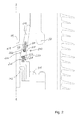
- Fig. 1 schematically shows a longitudinal section of a part of an embodiment of the breaker for medium and/or high voltage, e.g. 1-1000 kV, such as 12, 24 or 36 kV, according to the present invention, in a closed position (a conducting or connected state), and also in an open position (a non-conducting or disconnected state).
- a closed position a conducting or connected state
- an open position a non-conducting or disconnected state
- the breaker is substantially rotation symmetric around the axis z-z, and thus, the entire structure of the breaker in the open position is obtained by rotating the section to the right of the axis z-z 360 degrees about the axis z-z, and the entire structure of the breaker in the closed position is obtained by rotating the section to the left of the axis z-z 360 degrees about the axis z-z.
- the breaker comprises a first and a second arcing contact member 102, 104 movable in relation to one another to at least one closed position (shown to the left of the axis z-z) where the arcing contact members 102, 104 are electrically connected to one another, and to at least one open position (shown to the right of the axis z-z) where the arcing contact members 102, 104 are disconnected from one another and form an electrically insulating gap 106 between them.
- the first arcing contact members 102 is tubular and the second arcing contact members 104 has the shape of a cylindrical rod.
- the breaker comprises a first and a second rated current contact member 108, 110 movable in relation to one another to at least one closed position (shown to the right of the axis z-z) where the rated current contact members 108, 110 are electrically connected to one another, and to at least one open position (shown to the left of the axis z-z) where the rated current contact members 108, 110 are separated from each other, and form a second insulating gap 112 between them.
- the first and second rated current contact members 108, 110 are both tubular.
- the contact members 102, 104, 108, 110 may have other shapes and designs.
- the first arcing contact member 102 and the first rated current contact member 108 are adapted to be connected to the load (ground) side of an electric system to which the breaker is connected, and the other two contact members 104, 110 are adapted to be connected to the high voltage (source) side of the electric system.
- the other two contact members 104, 110 are adapted to be connected to the high voltage (source) side of the electric system.
- the breaker includes a tubular housing 114 which is made of an insulating material and defines a longitudinal axis z-z.
- the exterior of the housing 114 is in a conventional way provided with wing-shaped sheds 116 made of a polymer material, e.g. silicone.
- the housing 114 houses the contact members 102, 104, 108, 110 and separates the insulating gaps 106, 112 from an atmosphere outside the housing 114, and the housing 114 is filled with an electrically insulating gas, e.g. comprising CO 2 , N 2 , air, or SF 6 , e.g. compressed insulating gas.
- the housing 114 also defines a space between its inner periphery and the contact members 102, 104, 108, 110.
- first arcing contact member 102 and the first rated current contact member 108 are movable in relation to the housing 114, whereas the second arcing contact member 104 and the second rated current contact member 110 are stationary in relation to the housing 114.
- the main current path is provided via the first and second rated current contact members 108, 110.
- the rated current contact members 108, 110 are disconnected from one another by axially moving the rated current contact member 108 and the first arcing contact member 102 downward in Fig. 1 , while the arcing contact members 102, 104 maintain their connection to one another.
- the arcing contact members 102, 104 are disconnected from one another.
- the breaker includes a tubular shaped nozzle 202, 302, 402 which is adapted to be positioned around the insulating gap 106, and the nozzle 202 is adapted to guide electrically insulating gas to the insulating gap 106, for preventing arcing between the arcing contact members 102, 104 when separating them.
- the nozzle 202 is adapted to guide the insulating gas via at least one channel 118.
- the breaker is provided with a mechanism and a control system to control the breaker and the movement of the movable contact members, and the breaker is provided with conventional equipment to provide the nozzle with a flow of insulating gas in order to guide insulating gas to the insulating gap.
- nozzle 202, 302, 402 are shown in more detail.
- Each nozzle is adapted to be installed in a breaker for medium and/or high voltage, e.g. 1-1000 kV, such as the breaker shown in Fig. 1 .
- Each nozzle 202, 302, 402 is made partially, and to the major part, of a solid electrically insulating material 204, 304, 404, e.g. a dielectric material, e.g. PTFE, but other insulating materials, e.g. composite materials, may also be used.
- the nozzle 202 is physically connected to the first arcing contact member 102 and to the first rated current contact member 108, and the nozzle 202 is adapted to move together with the first arcing contact member 102 and the first rated current contact member 108 in relation to the housing 114 and in relation to the stationary second arcing contact member 104 and the stationary second rated current contact member 110.
- the nozzle comprises a nozzle portion 206, 306, 406 adapted to be positioned in the region of the insulating gap 106 between the arcing contact members 102, 104.
- the nozzle 202 is adapted to project, at least partially in the open position, between the first arcing contact member 102 and the first rated current contact member 108, and between the second arcing contact member 104 and the second rated current contact member 110.
- the open position when the arcing contact members 102, 104 are disconnected, the nozzle portion 206, 306, 406 is adjacent to the insulating gap, and the nozzle 202 separates the insulating gap 106 from the second insulating gap 112 between the rated current contact members 108, 110.
- the nozzle 202 includes a first electrically conductive body 208 and a second electrically conductive body 210 both being entirely surrounded by the insulating material 204 of the nozzle 202 and electrically insulated from the contact members 102, 104, 108, 110 and from earth/ground.
- the electrically conductive bodies 208, 210 are annular, ring-shaped, or tubular shaped, and adapted to be positioned around the insulating gap 106, and are spaced apart by a distance, the distance being filled with the insulating material 204.
- the electrically conductive body 208 on the load (ground) side could be electrically connected to earth, by suitable means.
- one of the electrically conductive bodies 208 could be partially surrounded by the insulating nozzle material 204 instead of entirely surrounded.
- the conductive bodies 208, 210 are adapted to form a capacitive coupling between them, and there is a capacitance between the conductive bodies 208, 210.
- the conductive bodies 208, 210 are formed by a solid conducting material.
- Each conductive body 208, 210 comprises an outer surface 212, 214 facing the insulating nozzle material 204, and a surface portion 216, 218 of the outer surface 212, 214 of the conductive bodies 208, 210 comprises a nonlinear field grading material, FGM, e.g. a resistive field grading material with a field dependent electrical resistivity, e.g. SiC or ZnO fillers in a suitable polymer base.
- FGM nonlinear field grading material
- the surface portion 216, 218 is advantageously formed by a layer of FGM, which e.g. is applied to the conductive body, e.g. by covering.
- the FGM layer has a suitable thickness.
- each conductive body 208, 210 has a suitable thickness and faces the adjacent other conductive body 208, 210, and is located at a shorter distance to the adjacent other conductive body 208, 210 in relation to the remainder portion of the outer surface 212, 214 of the conductive body 208, 210.
- Each conductive body 208, 210 also has a terminal portion 220, 222 facing the adjacent other conductive body 208, 210, and the terminal portion 220, 222 is convex towards the adjacent other conductive body 208, 210.
- the conductive body 208, 210 has a longitudinal extension toward the adjacent other conductive body 208, 210 and defines a longitudinal axis.
- the convex terminal portion 220, 222 may have a radial extension which exceeds the radial extension of the remainder portion of the conductive body 208, 210.
- the nozzle 302 includes three conductive bodies 308, 310, 312 all being entirely surrounded by the insulating material 304 of the nozzle 302 and electrically insulated from the contact members 102, 104, 108, 110 and from earth/ground.
- the electrically conductive bodies 308, 310, 312 are annular, ring-shaped or tubular, and adapted to be positioned around the insulating gap 106, and are spaced apart by distances, and are adapted to form capacitive couplings between them.
- the nozzle 302 comprises one compartment 314 formed by the insulating nozzle material 302, each compartment 314 having a wall surface 316.
- Each conductive body 308, 310, 312 comprises at least one electrically conductive layer 318
- the wall surface 316 comprises the at least one electrically conductive layer 318.
- the compartment, the wall surface and the conductive layer are only shown with regard to one of the conductive bodies 310, but a plurality or all of the conductive bodies may naturally be designed in a corresponding way.
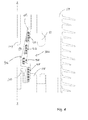
- the nozzle 402 includes four conductive bodies 408, 410, 412, 414 all being entirely surrounded by the insulating material 404 of the nozzle 402 and electrically insulated from the contact members 102, 104, 108, 110 and from earth/ground.
- the electrically conductive bodies 408, 410, 412, 414 are annular, ring-shaped or tubular, and adapted to be positioned around the insulating gap 106, and are spaced apart by distances, and are adapted to form capacitive couplings between them.
- Each conductive body 408, 410, 412, 414 is formed by an electrically conductive liquid material filled into a compartment which the insulating nozzle material 404 forms for each conductive body 408, 410, 412, 414.
- the above-mentioned embodiments of the nozzle could also be provided with more conductive bodies, e.g. more than four conductive bodies, and the different kinds of conductive bodies could be mixed in one and the same nozzle.
- Other kinds and shapes of the conductive bodies are possible.
- the second and third embodiments of the nozzle may also be provided with FGM in a corresponding way as is disclosed in connection with the first embodiment of Fig. 2 .
- each conductive body The shape of each conductive body, the size of each conductive body in relation to the size of the nozzle, the distance between two adjacent conductive bodies, the position of each conductive body within the insulating nozzle material in relation to the surroundings are based on and optimized for the design of the arcing contact members, the arcing contact member separation speed, the overall structure of the breaker, the properties of the insulating nozzle material, the composition of the insulating gas used in the breaker, the critical distance between the arcing contact members where the risk of re-strike is highest, and the electric field pattern in the region of the insulating gap between the arcing contact members. Especially the distance between adjacent conductive bodies is important for the optimization.
Landscapes
- Circuit Breakers (AREA)
Abstract
Description
- The present invention relates to a nozzle for a medium and/or high voltage breaker, the breaker comprising at least two arcing contact members movable in relation to one another to at least one closed position where the arcing contact members are electrically connected to one another, and to at least one open position where the arcing contact members are disconnected from one another and form an electrically insulating gap between them. The nozzle is made partially of an electrically insulating material and is adapted to guide electrically insulating gas to the insulating gap, for preventing arcing between the arcing contact members when separating or connecting them. The nozzle comprises a nozzle portion adapted to be positioned in the region of the electrically insulating gap, and the nozzle comprises a first electrically conductive body which is entirely surrounded by the insulating material of the nozzle and electrically insulated from the arcing contact members. Further, the present invention relates to a breaker for medium and/or high voltage comprising a nozzle of the above-mentioned sort.
- Breakers for medium and/or high voltage, e.g. 1 -1000 kV, which may also be called power breakers, circuit breakers, or interrupters, are provided in medium and/or high voltage electric systems to interrupt the electric circuit upon occurrence of specific operational conditions. The basic structure of breakers and their applications are well known to the person skilled in the art, and breakers can for example be installed in switchgears.
- Breakers may comprise a housing which houses the contact members, or electrodes, of the breaker, and the housing may be filled with an electrically insulating gas, e.g. compressed gas. It is previously known to install an electrically insulating nozzle, e.g. formed by a dielectric material, in the gas-filled breaker. The nozzle is movable in relation to at least one contact member and is adapted to be positioned in the region of the electrically insulating gap which is formed between two separated contact members, more precisely the arcing contact members. The nozzle is adapted to guide a flow of electrically insulating gas to the insulating gap for preventing arcing during opening and closing operations. The flow of electrically insulating gas guided to the insulating gap by the nozzle can be said to blow out an arc which is struck between the two arcing contact members. In prior art, various designs of the features of the breaker are suggested in order to improve the performance or the structure of the breaker.
-
US 4,420,662 discloses a compressed-gas circuit breaker with two contact members which move in relation to one another, and a nozzle made of a dielectric material and attached to one of the contact members. An annular insert made of a conductive material is provided at the nozzle constriction. -
JP 02-168524 -
JP 10-199382 -
DE 42 05 501-C1 discloses a high voltage breaker having two arc contacts and two rated current contacts, and a nozzle provided with one metal sleeve. The metal sleeve may be provided on the outside of the nozzle, or may be embedded inside the nozzle. -
US 2009/0261070-A1 describes an insulating nozzle made of two different materials, and both of the materials may be electrically insulating materials. -
GB 712,785 -
WO 2008/043721-A1 describes an insulating tube provided around the insulating nozzle of an interrupter. A second material may be moulded onto the inside or outside of the insulating tube. -
DE 39 04 147-A1 discloses a metal-encapsulated, gas-blast power circuit breaker. In the region of the switching path, metallic fitting bodies, which at the same time form control rings, are fitted on the circumference of an insulating tube which accommodates the contact tubes of the breaker. -
US 6,462,295-B1 describes a high voltage power breaker having two arc contacts and two rated current contacts, and an insulating nozzle projecting at least partially into the insulating gap between the contacts. The insulating nozzle has an annular filling attached to its outer circumference and made of insulating material having a dielectric constant above three. -
EP 1 544 881-A1 discloses a nozzle for a gas-insulated switching device having a couple of separable arc contacts, and the nozzle has a hollow body comprising an electrically insulating portion and an annular conductive body partially surrounded by the insulating portion. -
EP 1 772 882-A1 describes a gas-insulated breaker having an insulating nozzle. Onto the outer circumference of the nozzle, or in an open groove in the outer circumference of the nozzle, one or more electrically conductive or dielectric field element may be mounted. -
CA 1077100 discloses a disconnect contact assembly for metal-clad switchgear, where nonlinear semiconductor coatings may be provided onto the surface of a tubular insulator which surrounds a conductive stud of the disconnect contact assembly. - When separating the arcing contact members of a breaker, the arcing contact members are subjected to electric field stress because of the electric field produced in the insulating gap between the arcing contact members upon separation, which may impair the performance of the breaker and may result in wear on the arcing contact members.
- The object of the present invention is to provide an improved breaker for medium and/or high voltage. It is a further object of the present invention to prevent secondary arcing between contact members of a breaker for medium and/or high voltage. It is also an object of the present invention to prevent wear on the arcing contact members of a breaker for medium and/or high voltage.
- The above-mentioned objects of the present invention are attained by providing a nozzle for a medium and/or high voltage (e.g. 1 -1000 kV) breaker, the breaker comprising at least two arcing contact members movable in relation to one another to at least one closed position where the arcing contact members are electrically connected to one another, and to at least one open position where the arcing contact members are disconnected from one another and form an electrically insulating gap between them, the nozzle being made partially of an electrically insulating material and being adapted to guide electrically insulating gas to the insulating gap, for preventing arcing between the arcing contact members when separating or connecting them, the nozzle comprises a nozzle portion adapted to be positioned in the region of the electrically insulating gap, and the nozzle comprises a first electrically conductive body which is entirely surrounded by the insulating material of the nozzle and electrically insulated from the arcing contact members, wherein the nozzle comprises at least one second electrically conductive body which is at least partially surrounded by the insulating material of the nozzle and electrically insulated from the arcing contact members, wherein the at least one second electrically conductive body is spaced from the first electrically conductive body by a distance, wherein the conductive bodies are adapted to form a capacitive coupling between them, for electric field control in the insulating gap, and wherein at least one of the conductive bodies is electrically insulated from earth.
- Thus, the nozzle comprises a first part in the form of the insulating material, and a second part in the form of the conductive bodies.
- The conductive bodies are adapted to form a capacitive coupling between them such that efficient electric field control in the insulating gap is provided, e.g. such that an advantageous electric field distribution is formed in the insulating gap.
- By combining the first electrically conductive body, which is entirely surrounded by the insulating nozzle material (i.e. the insulating material of the nozzle), with the at least one second electrically conductive body, which is at least partially surrounded by the insulating nozzle material, the electric field stress is efficiently displaced from the arcing contact members to the nozzle material and to the region between the conductive bodies, which has been shown in tests performed by the inventors of the present invention, whereby field stress on the arcing contact members is reduced. The maximum electric field between the arcing contact members in the insulating gap is efficiently reduced. Because of the reduced electric field stress on the arcing contact members, the risk of secondary arching, also called re-strike, between the arcing contact members is efficiently reduced. By entirely embedding and enclosing one of the electrically conductive bodies, any triple point with regard to this body is excluded, resulting in a reduced electric field level. When an electrically conductive body is not entirely surrounded by the insulating nozzle material but has an exposed surface in contact with the insulating gas, a triple point is formed between the conducting material of the conductive body, the insulating gas and the insulating material of the nozzle, and a triple point results in high electric field. A high electric field increases the risk of secondary arching between the arcing contact members, and increases the risk of electrical breakdown in the insulating nozzle material or in the insulating gas. Further, as a result of the present invention, a breaker which can withstand increased voltage levels is provided.
- A dielectric material which is stressed beyond its dielectric strength undergoes an electrical breakdown. This results in the sudden transition of part of the dielectric material from an insulating state to a highly conductive state. This transition is characterized by the formation of an electric spark, and possibly an electric arc channel through the material. If an electrical breakdown occurs within a solid dielectric, e.g. within an insulating nozzle material, physical, chemical and structural changes along the path of the discharge will cause permanent degradation and significant reduction in the dielectric strength of the insulating material.
- The inventors have realized that the problem of electric stress may be easier to handle within the insulating nozzle material than in the insulating gas. By providing the at least two conductive bodies within the insulating nozzle material according to the present invention, the "electric stress problem" is moved into the nozzle material, where the electric stress is efficiently taken care of by the inventive design of the nozzle.
- In prior art, there are critical requirements with regard to the driving system which is adapted to control the relative movement of the arcing contact members, normally by controlling the movement of one of the arcing contact members, whereas the other is stationary, since the separation of the arcing contact members must be fast enough to provide a gap between the arcing contact members which is sufficiently large when the Transient Recovery Voltage, TRV, i.e. the voltage which appears across the circuit terminals due to redistribution of trapped energy between source and load side of the network, to which the breaker is connected, appears across the arcing contact members. If not, the electric field in the insulating gap will be too high, resulting in secondary arcing. By the present invention, the speed requirements with regard to the moving arcing contact members can be reduced and the moving arcing contact members does not need to move as fast as in prior art. As a result, the mechanism of the driving system can be less sophisticated, be more light-weight and less expensive, resulting in a less complicated, more compact and less bulky breaker, which has a reduced weight in relation to prior art breakers.
- By the present invention, and the efficient decrease of the electric field strength in the insulating gap between the two arcing contact members, the breaker can use an insulating gas which has a lower breakdown voltage than SF6. Sulphur hexafluoride, SF6, may e.g. be replaced by CO2, N2, or even air, which are more environmentally friendly gases in relation to SF6, and thus, a more environmentally friendly breaker may be provided. By the present invention, and for the reasons mentioned above, an improved nozzle is provided. The improved nozzle provides an improved breaker for medium and/or high voltage, which is subjected to less stress and is more durable.
- The distance between the at least one second electrically conductive body and the first electrically conductive body may be set and optimized based on the design of the arcing contact members, the arcing contact member separation speed, the overall structure of the breaker, the composition of the insulating gas used in the breaker, and the electric field pattern in the region of the insulating gap between the arcing contact members.
- The nozzle may have a tubular shape and may be adapted to be positioned around the insulating gap, the nozzle portion may e.g. be tubular, and the conductive bodies may advantageously be annular, ring-shapes and/or tubular, and adapted to be positioned around the insulating gap.
- According to a further advantageous embodiment of the nozzle according to the present invention, the conductive bodies may be optimized in their shape and spatial location so that the breaker, in order to improve the re-strike performance, experiences the least stress in the arcing gaps when the arcing contact members reach half-way between closed and fully open positions along the travel path.
- According to another advantageous embodiment of the nozzle according to the present invention, the at least one second electrically conductive body is entirely surrounded by the insulating material of the nozzle.
- By this embodiment, any triple point with regard to all the conductive bodies is excluded, and a further electric field strength reduction in the region of the insulating gap is efficiently provided, which has been shown in tests performed by the inventors of the present invention. The above-mentioned positive effects of the present invention are thus further enhanced, and a further improved nozzle and breaker for medium and/or high voltage are provided.
- According to an advantageous embodiment of the nozzle according to the present invention, both the first electrically conductive body and the at least one second electrically conductive body are electrically insulated from earth. By having both conductive bodies insulated from the earth/ground, it is easier to manufacture the nozzle, to install the nozzle in the breaker, and to assemble the breaker, since the second conductive body does not have to be electrically connected to earth, e.g. by a wire etc. The nozzle is just put in place inside the breaker. Hereby, a further improved nozzle and breaker for medium and/or high voltage are provided.
- According to a further advantageous embodiment of the nozzle according to the present invention, said nozzle portion comprises at least one of the conductive bodies. According to another advantageous embodiment of the nozzle according to the present invention, said nozzle portion comprises the first electrically conductive body and the at least one second electrically conductive body. The nozzle portion may be tubular and adapted to be positioned around the insulating gap. Advantageously, in the open position, the nozzle portion is adapted to be positioned adjacent to the insulating gap.
- The insulating material of the nozzle can for example be formed by one polymer or a plurality of polymers, e.g. a composite material, and suitable polymers are known to the skilled person.
- According to still another advantageous embodiment of the nozzle according to the present invention, the insulating material of the nozzle comprises a dielectric material. Examples of suitable dielectric materials are well known to the skilled person.
- According to yet another advantageous embodiment of the nozzle according to the present invention, each conductive body comprises an outer surface facing the insulating material of the nozzle, and at least one surface portion of the outer surface of at least one of the conductive bodies comprises a nonlinear field grading material, FGM. The at least one surface portion may be formed by a layer of FGM, for example, by covering a portion of the conductive body with a layer of FGM. The FGM layer may have a suitable thickness. Alternatively, the entire outer surface of the conductive body may comprise FGM, and the outer surface may be formed by a layer of FGM.
- By the inventive provision of the field grading material, the inventors of the present invention address the increased risk of an electrical breakdown in the insulating nozzle material because of the increased electric field strength in the insulating nozzle material. The inventors have identified that the electric field strength is highest at the surface of the conductive body. By introducing the nonlinear field grading material according to this embodiment, the electric field at the surface of the conductive body is efficiently distributed, or smoothed out, and the electric field stress on the conductive body surface and on the insulating nozzle material is reduced, and the risk of an electrical breakdown in the insulating nozzle material is efficiently reduced.
- A field grading material is a material adapted to grade or to guide the electric field. Examples of so called field grading material, FGM, which can be used as defined by the advantageous embodiments of the nozzle according to the present invention, are for example mentioned in
WO-A1-2008/076058 andEP-A1-1 736 998 . However, other suitable FGM may also be used. - According to an advantageous embodiment of the nozzle according to the present invention, the nonlinear field grading material is a resistive field grading material with a resistivity which is a function of the electric field. Alternatively, a capacitive field grading material with field dependent permittivity may be used.
- By introducing a resistive nonlinear field grading material according to this embodiment, the reduction of the electric field strength at the surface of the conductive body is further improved, the electric field stress on the insulating nozzle material is further reduced, and the risk of an electrical breakdown in the insulating nozzle material is further reduced.
- According to a further advantageous embodiment of the nozzle according to the present invention, the at least one surface portion of at least one of the conductive bodies faces an adjacent other conductive body. The inventors of the present invention have found that the electric field is highest at the surface of the conductive body which faces another conductive body. By this embodiment, the reduction of the electric field strength at the surface of the conductive body is further improved, and the risk of an electrical breakdown in the insulating nozzle material is further reduced.
- According to another advantageous embodiment of the nozzle according to the present invention, the at least one surface portion of at least one of the conductive bodies is located at a shorter distance to an adjacent other conductive body in relation to the remainder portion of the outer surface of the conductive body comprising the at least one surface portion.
- The inventors of the present invention have found that the electric field is highest at the surface of the conductive body where the distance to another conductive body is the shortest. By this embodiment, the reduction of the electric field strength at the surface of the conductive body is still further improved, and the risk of an electrical breakdown in the insulating nozzle material is still further reduced.
- According to yet another advantageous embodiment of the nozzle according to the present invention, at least one of the conductive bodies has a terminal portion facing an adjacent other conductive body, and the terminal portion is convex towards the adjacent other conductive body. By giving the conductive body a smoothly curved surface towards an adjacent other conductive body, the inventors of the present invention have found, i.e. via tests performed by them, that the electric field at the surface of the conductive body is efficiently distributed, or smoothed out, and the electric field strength at the conductive body surface is further reduced, and a further reduced risk of an electrical breakdown in the insulating nozzle material is attained.
- According to another advantageous embodiment of the nozzle according to the present invention, the conductive body, which has the convex terminal portion, has a longitudinal extension toward an adjacent other conductive body and defines a longitudinal axis, and the convex terminal portion has a radial extension which exceeds the radial extension of the remainder portion of the conductive body having the convex terminal portion. This embodiment further improves the distribution of the electric field at the surface of the conductive body, which has been shown in tests performed by the inventors of the present invention, and a still further reduced risk of an electrical breakdown in the insulating nozzle material is attained.
- The above-mentioned reduced risk of an electrical breakdown in the insulating nozzle material, as a result of the inventive and efficient electric field control, provides an efficiently improved nozzle, which in turn provides an efficiently improved breaker for medium and/or high voltage.
- The material of the conductive bodies may for example comprise graphite, carbon black, metal oxides, mercury etc. However, other materials for the conductive bodies are possible.
- According to still another advantageous embodiment of the nozzle according to the present invention, at least one conductive body comprises an electrically conductive liquid material filled into a compartment formed by the insulating material of the nozzle.
- It may be complicated to add and embed a second material into the nozzle material, e.g. when the insulating material of the nozzle is formed by polytetrafluoroethylene, PTFE, which has weak adhesion properties, and because the different materials may have different thermal expansion and contraction properties. By using a liquid material for the conductive bodies, e.g. an electrically conducting gel or oil, the problems of the difference in thermal expansion and contraction properties are overcome. The manufacturing of the nozzle is also facilitated, which provides for a less expensive nozzle, and a consequently a less expensive breaker. Suitable electrically conducting liquids, such as gels or oils, are known to the person skilled in the art. According to an advantageous embodiment of the nozzle according to the present invention, the insulating nozzle material is formed by fluorinated ethylene propylene, FEP. FEP may be easier to process in relation to PTFE. According to another advantageous embodiment of the nozzle according to the present invention, an adhesive, for example an epoxy adhesive, can be provided between the conductive body and the insulating nozzle material, in order to facilitate the provision of the conductive body inside the insulating nozzle material.
- According to an advantageous embodiment of the nozzle according to the present invention, the nozzle comprises at least one compartment formed by the insulating material of the nozzle, the compartment having a wall surface, at least one conductive body comprises at least one electrically conductive layer, and the wall surface comprises the at least one electrically conductive layer. By this embodiment, hollow conductive bodies are provided, which also reduces the problems of the difference in thermal expansion and contraction properties. Further, the hollow conductive bodies add little weight to the nozzle, whereby a light-weight nozzle, and consequently a light-weight breaker, may be provided. The light-weight nozzle requires a less sophisticated driving mechanism for controlling the arcing contact member to which the nozzle may be physically connected. An improved nozzle and breaker are thus provided.
- According to a further advantageous embodiment of the nozzle according to the present invention, the nozzle comprises at least two second electrically conductive bodies. By this embodiment, the nozzle is provided with at least three embedded conductive bodies. By providing more than two conductive bodies, there are more distances between conductive bodies which may be adjusted and optimized for a particular breaker design, and the re-strike prevention and breakdown prevention can be tailored and adapted in a more sophisticated way for a particular breaker design, whereby a further improved breaker can be provided.
- The above-mentioned objects of the present invention are also attained by providing a breaker for medium and/or high voltage, e.g. 1-1000 kV, comprising at least two arcing contact members movable in relation to one another to at least one closed position where the arcing contact members are electrically connected to one another, and to at least one open position where the arcing contact members are disconnected from one another and form an electrically insulating gap between them, and a nozzle adapted to guide electrically insulating gas to the insulating gap, for preventing arcing between the arcing contact members when separating or connecting them, wherein the nozzle comprises the features mentioned in any of the appended claims 1 to 10, or the features of any of the above-mentioned embodiments of the nozzle. Hereby, an improved breaker is provided for reasons stated above in connection with the disclosure of the nozzle according to the present invention.
- According to an advantageous embodiment of the breaker according to the present invention, the nozzle is physically connected to a movable first arcing contact member of the arcing contact members, and the nozzle is adapted to move together with the first arcing contact member in relation to the other arcing contact member. This is an efficient way to mount the nozzle and control the movement of the nozzle inside the breaker.
- According to a further advantageous embodiment of the breaker according to the present invention, the breaker comprises at least two rated current contact members movable in relation to one another to at least one closed position where the rated current contact members are electrically connected to one another, and to at least one open position where the rated current contact members are separated from each other, and the electrically conductive bodies are insulated from the at least two rated current contact members. By the nozzle according to the present invention, an efficient breaker, having at least two rated current contact members and at least two arcing contact members, is provided.
- According to another advantageous embodiment of the breaker according to the present invention, the breaker comprises a housing which houses the contact members and the nozzle, the housing separates the insulating gap from an atmosphere outside the housing, and the housing is filled with the insulating gas. By the nozzle according to the present invention, an efficient insulating gas-filled breaker is provided.
- According to yet another advantageous embodiment of the breaker according to the present invention, the insulating gas comprises CO2. By the present invention, and the efficient decrease of the electric field strength in the insulating gap between the two arcing contact members, one can use CO2 instead of the insulating gas SF6. SF6 has a higher dielelectric strength and a higher breakdown voltage than CO2. CO2 is more environmentally friendly than SF6, and by this embodiment a more environmentally friendly breaker is provided. However, the insulating gas of the breaker may also comprise other insulating gases, e.g. N2, air, and even SF6.
- According to an advantageous embodiment of the breaker according to the present invention, the dielectric strength of the insulating nozzle material is higher than the dielectric strength of the insulating gas contained in the housing of the breaker. Tests performed by the inventors have shown that this is an advantageous relationship, which provides an efficient control of the electric field, and provides an improved breaker. However, other relationships between the dielectric strength of the insulating nozzle material and the insulating gas, respectively, are also possible.
- The above-mentioned embodiments and features of the nozzle and breaker, respectively, may be combined in various possible ways providing further advantageous embodiments.
- Further advantageous embodiments of the nozzle and the breaker according to the present invention and further advantages with the present invention emerge from the detailed description of embodiments.
- The present invention will now be described, for exemplary purposes, in more detail by way of embodiments and with reference to the enclosed drawings, in which:
- Fig. 1
- is a schematic side view showing a longitudinal section of a part of an embodiment of the breaker according to the present invention, to the left of the axis of symmetry z-z the breaker being shown in a closed position, and to the right of the axis z-z the breaker being shown in an open position;
- Fig. 2
- is a schematic side view showing a longitudinal section of a first embodiment of the nozzle according to the present invention, when the breaker is in an open position;
- Fig. 3
- is a schematic side view showing a longitudinal section of a second embodiment of the nozzle according to the present invention; and
- Fig. 4
- is a schematic side view showing a longitudinal section of a third embodiment of the nozzle according to the present invention.
-
Fig. 1 schematically shows a longitudinal section of a part of an embodiment of the breaker for medium and/or high voltage, e.g. 1-1000 kV, such as 12, 24 or 36 kV, according to the present invention, in a closed position (a conducting or connected state), and also in an open position (a non-conducting or disconnected state). To the left of the axis of symmetry z-z the breaker is shown in the closed position, and to the right of the axis z-z the breaker is shown in the open position. The breaker is substantially rotation symmetric around the axis z-z, and thus, the entire structure of the breaker in the open position is obtained by rotating the section to the right of the axis z-z 360 degrees about the axis z-z, and the entire structure of the breaker in the closed position is obtained by rotating the section to the left of the axis z-z 360 degrees about the axis z-z. - The breaker comprises a first and a second
arcing contact member arcing contact members arcing contact members gap 106 between them. The firstarcing contact members 102 is tubular and the secondarcing contact members 104 has the shape of a cylindrical rod. Further, the breaker comprises a first and a second ratedcurrent contact member current contact members current contact members current contact members contact members - In this embodiment, the first
arcing contact member 102 and the first ratedcurrent contact member 108 are adapted to be connected to the load (ground) side of an electric system to which the breaker is connected, and the other twocontact members - The breaker includes a
tubular housing 114 which is made of an insulating material and defines a longitudinal axis z-z. The exterior of thehousing 114 is in a conventional way provided with wing-shaped sheds 116 made of a polymer material, e.g. silicone. Thehousing 114 houses thecontact members gaps 106, 112 from an atmosphere outside thehousing 114, and thehousing 114 is filled with an electrically insulating gas, e.g. comprising CO2, N2, air, or SF6, e.g. compressed insulating gas. Thehousing 114 also defines a space between its inner periphery and thecontact members - In this embodiment, the first
arcing contact member 102 and the first ratedcurrent contact member 108 are movable in relation to thehousing 114, whereas the secondarcing contact member 104 and the second ratedcurrent contact member 110 are stationary in relation to thehousing 114. - When the breaker is in the closed (connected) position, the main current path is provided via the first and second rated
current contact members current contact members current contact member 108 and the firstarcing contact member 102 downward inFig. 1 , while thearcing contact members current contact member 108 and the firstarcing contact member 102 in a downward direction, thearcing contact members current contact members contact members current contact members - The breaker includes a tubular shaped
nozzle gap 106, and thenozzle 202 is adapted to guide electrically insulating gas to the insulatinggap 106, for preventing arcing between the arcingcontact members nozzle 202 is adapted to guide the insulating gas via at least one channel 118. - In a conventional way known to the person skilled in the art, the breaker is provided with a mechanism and a control system to control the breaker and the movement of the movable contact members, and the breaker is provided with conventional equipment to provide the nozzle with a flow of insulating gas in order to guide insulating gas to the insulating gap.
- In
Figs. 2-4 , embodiments of thenozzle Fig. 1 . - Each
nozzle material nozzle 202 is physically connected to the firstarcing contact member 102 and to the first ratedcurrent contact member 108, and thenozzle 202 is adapted to move together with the firstarcing contact member 102 and the first ratedcurrent contact member 108 in relation to thehousing 114 and in relation to the stationary secondarcing contact member 104 and the stationary second ratedcurrent contact member 110. The nozzle comprises anozzle portion gap 106 between the arcingcontact members nozzle 202 is adapted to project, at least partially in the open position, between the firstarcing contact member 102 and the first ratedcurrent contact member 108, and between the secondarcing contact member 104 and the second ratedcurrent contact member 110. In the open position, when thearcing contact members nozzle portion nozzle 202 separates the insulatinggap 106 from the second insulating gap 112 between the ratedcurrent contact members - With reference to
Fig. 2 , a first embodiment of thenozzle 202 according to the present invention is schematically shown. Thenozzle 202 includes a first electrically conductive body 208 and a second electricallyconductive body 210 both being entirely surrounded by the insulating material 204 of thenozzle 202 and electrically insulated from thecontact members conductive bodies 208, 210 are annular, ring-shaped, or tubular shaped, and adapted to be positioned around the insulatinggap 106, and are spaced apart by a distance, the distance being filled with the insulating material 204. Alternatively, the electrically conductive body 208 on the load (ground) side could be electrically connected to earth, by suitable means. Alternatively, one of the electrically conductive bodies 208 could be partially surrounded by the insulating nozzle material 204 instead of entirely surrounded. Theconductive bodies 208, 210 are adapted to form a capacitive coupling between them, and there is a capacitance between theconductive bodies 208, 210. In the first embodiment, theconductive bodies 208, 210 are formed by a solid conducting material. Eachconductive body 208, 210 comprises anouter surface 212, 214 facing the insulating nozzle material 204, and asurface portion outer surface 212, 214 of theconductive bodies 208, 210 comprises a nonlinear field grading material, FGM, e.g. a resistive field grading material with a field dependent electrical resistivity, e.g. SiC or ZnO fillers in a suitable polymer base. Thesurface portion WO-A1-2008/076058 andEP-A1-1 736 998 for examples of FGM which may used. However, other suitable FGM may also be used. Thesurface portion conductive body 208, 210 has a suitable thickness and faces the adjacent otherconductive body 208, 210, and is located at a shorter distance to the adjacent otherconductive body 208, 210 in relation to the remainder portion of theouter surface 212, 214 of theconductive body 208, 210. Eachconductive body 208, 210 also has aterminal portion 220, 222 facing the adjacent otherconductive body 208, 210, and theterminal portion 220, 222 is convex towards the adjacent otherconductive body 208, 210. Theconductive body 208, 210 has a longitudinal extension toward the adjacent otherconductive body 208, 210 and defines a longitudinal axis. The convexterminal portion 220, 222 may have a radial extension which exceeds the radial extension of the remainder portion of theconductive body 208, 210. - With reference to
Fig. 3 , a second embodiment of thenozzle 302 according to the present invention is schematically shown. Thenozzle 302 includes threeconductive bodies 308, 310, 312 all being entirely surrounded by the insulatingmaterial 304 of thenozzle 302 and electrically insulated from thecontact members conductive bodies 308, 310, 312 are annular, ring-shaped or tubular, and adapted to be positioned around the insulatinggap 106, and are spaced apart by distances, and are adapted to form capacitive couplings between them. For eachconductive body 308, 310, 312, thenozzle 302 comprises onecompartment 314 formed by the insulatingnozzle material 302, eachcompartment 314 having awall surface 316. Eachconductive body 308, 310, 312 comprises at least one electricallyconductive layer 318, and thewall surface 316 comprises the at least one electricallyconductive layer 318. InFig. 3 , the compartment, the wall surface and the conductive layer are only shown with regard to one of theconductive bodies 310, but a plurality or all of the conductive bodies may naturally be designed in a corresponding way. - With reference to
Fig. 4 , a third embodiment of thenozzle 302 according to the present invention is schematically shown. The nozzle 402 includes fourconductive bodies material 404 of the nozzle 402 and electrically insulated from thecontact members conductive bodies gap 106, and are spaced apart by distances, and are adapted to form capacitive couplings between them. Eachconductive body nozzle material 404 forms for eachconductive body - Alternatively, the above-mentioned embodiments of the nozzle could also be provided with more conductive bodies, e.g. more than four conductive bodies, and the different kinds of conductive bodies could be mixed in one and the same nozzle. Other kinds and shapes of the conductive bodies are possible.
- The second and third embodiments of the nozzle may also be provided with FGM in a corresponding way as is disclosed in connection with the first embodiment of
Fig. 2 . - The shape of each conductive body, the size of each conductive body in relation to the size of the nozzle, the distance between two adjacent conductive bodies, the position of each conductive body within the insulating nozzle material in relation to the surroundings are based on and optimized for the design of the arcing contact members, the arcing contact member separation speed, the overall structure of the breaker, the properties of the insulating nozzle material, the composition of the insulating gas used in the breaker, the critical distance between the arcing contact members where the risk of re-strike is highest, and the electric field pattern in the region of the insulating gap between the arcing contact members. Especially the distance between adjacent conductive bodies is important for the optimization.
- The invention shall not be considered limited to the embodiments illustrated, but can be modified and altered in many ways by one skilled in the art, without departing from the scope of the appended claims.
Claims (15)
- A nozzle (202; 302; 402) for a medium and/or high voltage breaker, the breaker comprising at least two arcing contact members (102, 104) movable in relation to one another to at least one closed position where the arcing contact members are electrically connected to one another, and to at least one open position where the arcing contact members (102, 104) are disconnected from one another and form an electrically insulating gap (106) between them, the nozzle being made partially of an electrically insulating material (204; 304; 404) and being adapted to guide electrically insulating gas to the insulating gap (106), for preventing arcing between the arcing contact members when separating or connecting them, the nozzle comprises a nozzle portion (206; 306; 406) adapted to be positioned in the region of the electrically insulating gap, and the nozzle comprises a first electrically conductive body (208; 308; 408) which is entirely surrounded by the insulating material of the nozzle and electrically insulated from the arcing contact members, characterized in that the nozzle comprises at least one second electrically conductive body (210; 310, 312; 410, 412, 414) which is at least partially surrounded by the insulating material of the nozzle and electrically insulated from the arcing contact members, in that the at least one second electrically conductive body is spaced from the first electrically conductive body by a distance, in that the conductive bodies are adapted to form a capacitive coupling between them, for electric field control in the insulating gap, and in that at least one of the conductive bodies is electrically insulated from earth.
- A nozzle according to claim 1, characterized in that the at least one second electrically conductive body (210; 310, 312; 410, 412, 414) is entirely surrounded by the insulating material (204; 304; 404) of the nozzle.
- A nozzle according to claim 1 or 2, characterized in that both the first electrically conductive body and the at least one second electrically conductive body are electrically insulated from earth.
- A nozzle according to any of the claims 1 to 3, characterized in that each conductive body (208, 210) comprises an outer surface (212, 214) facing the insulating material (204) of the nozzle, and in that at least one surface portion (216, 218) of the outer surface of at least one of the conductive bodies (208, 210) comprises a nonlinear field grading material.
- A nozzle according to claim 4, characterized in that the at least one surface portion (216, 218) of at least one of the conductive bodies faces an adjacent other conductive body.
- A nozzle according to claims 4 or 5, characterized in that the at least one surface portion (216, 218) of at least one of the conductive bodies (208, 210) is located at a shorter distance to an adjacent other conductive body in relation to the remainder portion of the outer surface of the conductive body (208, 210) comprising the at least one surface portion.
- A nozzle according to any of the claims 1 to 6, characterized in that at least one of the conductive bodies (208, 210) has a terminal portion (220, 222) facing an adjacent other conductive body, and in that the terminal portion is convex towards the adjacent other conductive body (208, 210).
- A nozzle according to any of the claims 1 to 7, characterized in that at least one conductive body (408, 410, 412, 414) comprises an electrically conductive liquid material filled into a compartment formed by the insulating material of the nozzle.
- A nozzle according to any of the claims 1 to 8, characterized in that the nozzle (302) comprises at least one compartment (314) formed by the insulating material (304) of the nozzle, the compartment having a wall surface (316), in that at least one conductive body (310) comprises at least one electrically conductive layer (318), and in that the wall surface comprises the at least one electrically conductive layer.
- A nozzle according to any of the claims 1 to 9, characterized in that the nozzle comprises at least two second electrically conductive bodies.
- A breaker for medium and/or high voltage, comprising at least two arcing contact members (102, 104) movable in relation to one another to at least one closed position where the arcing contact members are electrically connected to one another, and to at least one open position where the arcing contact members are disconnected from one another and form an electrically insulating gap (106) between them, and a nozzle (202; 302; 402) adapted to guide electrically insulating gas to the insulating gap, for preventing arcing between the arcing contact members when separating or connecting them, characterized in that the nozzle (202; 302; 402) comprises the features mentioned in any of the claims 1 to 10.
- A breaker according to claim 11, characterized in that the nozzle (202; 302; 402) is physically connected to a movable first arcing contact member (102) of the arcing contact members, and in that the nozzle is adapted to move together with the first arcing contact member in relation to the other arcing contact member (104).
- A breaker according to claim 11 or 12, characterized in that the breaker comprises at least two rated current contact members (108, 110) movable in relation to one another to at least one closed position where the rated current contact members are electrically connected to one another, and to at least one open position where the rated current contact members are separated from each other, and in that the conductive bodies are insulated from the at least two rated current contact members.
- A breaker according to any of the claims 11 to 13, characterized in that the breaker comprises a housing (114) which houses the contact members and the nozzle, in that the housing separates the insulating gap (106) from an atmosphere outside the housing (114), and in that the housing is filled with the insulating gas.
- A breaker according to claim 14, characterized in that the insulating gas comprises CO2.
Priority Applications (1)
| Application Number | Priority Date | Filing Date | Title |
|---|---|---|---|
| EP20100154407 EP2362407B1 (en) | 2010-02-23 | 2010-02-23 | A nozzle for a breaker, and a breaker having such a nozzle |
Applications Claiming Priority (1)
| Application Number | Priority Date | Filing Date | Title |
|---|---|---|---|
| EP20100154407 EP2362407B1 (en) | 2010-02-23 | 2010-02-23 | A nozzle for a breaker, and a breaker having such a nozzle |
Publications (2)
| Publication Number | Publication Date |
|---|---|
| EP2362407A1 true EP2362407A1 (en) | 2011-08-31 |
| EP2362407B1 EP2362407B1 (en) | 2012-10-03 |
Family
ID=42333555
Family Applications (1)
| Application Number | Title | Priority Date | Filing Date |
|---|---|---|---|
| EP20100154407 Active EP2362407B1 (en) | 2010-02-23 | 2010-02-23 | A nozzle for a breaker, and a breaker having such a nozzle |
Country Status (1)
| Country | Link |
|---|---|
| EP (1) | EP2362407B1 (en) |
Cited By (4)
| Publication number | Priority date | Publication date | Assignee | Title |
|---|---|---|---|---|
| EP2629313A1 (en) * | 2012-02-17 | 2013-08-21 | ABB Technology AG | Gas-insulated circuit breaker with nominal contact shielding arrangement |
| DE102017212740A1 (en) * | 2017-07-25 | 2019-01-31 | Siemens Aktiengesellschaft | Power switching device, insulating nozzle for a power switching device and circuit system |
| WO2019073671A1 (en) * | 2017-10-12 | 2019-04-18 | 株式会社日立製作所 | Gas circuit breaker |
| EP3926654A1 (en) * | 2020-06-17 | 2021-12-22 | ABB Power Grids Switzerland AG | Circuit breaker with field deflection element |
Citations (14)
| Publication number | Priority date | Publication date | Assignee | Title |
|---|---|---|---|---|
| GB712785A (en) | 1951-04-12 | 1954-07-28 | Licentia Gmbh | Electric gas-blast circuit breakers |
| CA1077100A (en) | 1976-08-30 | 1980-05-06 | General Electric Company | Disconnect contact assembly for metal-clad switchgear and the like |
| US4420662A (en) | 1980-10-31 | 1983-12-13 | Bbc Brown, Boveri & Company Ltd. | Compressed-gas circuit breaker |
| JPH02168524A (en) | 1988-12-20 | 1990-06-28 | Meidensha Corp | Gas circuit breaker |
| DE3904147A1 (en) | 1989-02-07 | 1990-08-09 | Siemens Ag | METAL-ENCLOSED COMPRESSED GAS CIRCUIT BREAKER WITH RINGS USING FIELD CONTROL |
| DE4205501C1 (en) | 1992-02-22 | 1993-04-08 | Licentia Patent-Verwaltungs-Gmbh, 6000 Frankfurt, De | High tension switch preventing arcing when switched off - has two slidable contacts surrounded by insulating nozzle during on state, and control electrode surrounding nozzle. |
| JPH10199382A (en) | 1997-01-09 | 1998-07-31 | Nissin Electric Co Ltd | Puffer-type gas breaker |
| US6462295B1 (en) | 1999-01-20 | 2002-10-08 | Siemens Aktiengesellschaft | High-voltage power circuit breaker comprising an insulating nozzle |
| EP1544881A1 (en) | 2003-12-19 | 2005-06-22 | ABB Technology AG | Nozzle for a gas-insulated switching device and related switching device |
| EP1736998A1 (en) | 2005-06-21 | 2006-12-27 | Abb Research Ltd. | Varistor field control tape |
| EP1772882A1 (en) | 2005-10-10 | 2007-04-11 | Abb Research Ltd. | Compressed gas electrical breaker with arrangement for controlling the electric field |
| WO2008043721A1 (en) | 2006-10-09 | 2008-04-17 | Areva T & D Sa | Interrupter tube with field distribution cylinder for high- or medium-voltage circuit breakers |
| WO2008076058A1 (en) | 2006-12-20 | 2008-06-26 | Abb Research Ltd | Field grading material |
| US20090261070A1 (en) | 2006-07-24 | 2009-10-22 | Siemens Aktiengesellschaft | Insulating Nozzle, Comprising a First Material and a Second Material |
-
2010
- 2010-02-23 EP EP20100154407 patent/EP2362407B1/en active Active
Patent Citations (14)
| Publication number | Priority date | Publication date | Assignee | Title |
|---|---|---|---|---|
| GB712785A (en) | 1951-04-12 | 1954-07-28 | Licentia Gmbh | Electric gas-blast circuit breakers |
| CA1077100A (en) | 1976-08-30 | 1980-05-06 | General Electric Company | Disconnect contact assembly for metal-clad switchgear and the like |
| US4420662A (en) | 1980-10-31 | 1983-12-13 | Bbc Brown, Boveri & Company Ltd. | Compressed-gas circuit breaker |
| JPH02168524A (en) | 1988-12-20 | 1990-06-28 | Meidensha Corp | Gas circuit breaker |
| DE3904147A1 (en) | 1989-02-07 | 1990-08-09 | Siemens Ag | METAL-ENCLOSED COMPRESSED GAS CIRCUIT BREAKER WITH RINGS USING FIELD CONTROL |
| DE4205501C1 (en) | 1992-02-22 | 1993-04-08 | Licentia Patent-Verwaltungs-Gmbh, 6000 Frankfurt, De | High tension switch preventing arcing when switched off - has two slidable contacts surrounded by insulating nozzle during on state, and control electrode surrounding nozzle. |
| JPH10199382A (en) | 1997-01-09 | 1998-07-31 | Nissin Electric Co Ltd | Puffer-type gas breaker |
| US6462295B1 (en) | 1999-01-20 | 2002-10-08 | Siemens Aktiengesellschaft | High-voltage power circuit breaker comprising an insulating nozzle |
| EP1544881A1 (en) | 2003-12-19 | 2005-06-22 | ABB Technology AG | Nozzle for a gas-insulated switching device and related switching device |
| EP1736998A1 (en) | 2005-06-21 | 2006-12-27 | Abb Research Ltd. | Varistor field control tape |
| EP1772882A1 (en) | 2005-10-10 | 2007-04-11 | Abb Research Ltd. | Compressed gas electrical breaker with arrangement for controlling the electric field |
| US20090261070A1 (en) | 2006-07-24 | 2009-10-22 | Siemens Aktiengesellschaft | Insulating Nozzle, Comprising a First Material and a Second Material |
| WO2008043721A1 (en) | 2006-10-09 | 2008-04-17 | Areva T & D Sa | Interrupter tube with field distribution cylinder for high- or medium-voltage circuit breakers |
| WO2008076058A1 (en) | 2006-12-20 | 2008-06-26 | Abb Research Ltd | Field grading material |
Cited By (8)
| Publication number | Priority date | Publication date | Assignee | Title |
|---|---|---|---|---|
| EP2629313A1 (en) * | 2012-02-17 | 2013-08-21 | ABB Technology AG | Gas-insulated circuit breaker with nominal contact shielding arrangement |
| WO2013120944A1 (en) * | 2012-02-17 | 2013-08-22 | Abb Technology Ag | Gas-insulated circuit breaker with nominal contact shielding arrangement |
| CN104106121A (en) * | 2012-02-17 | 2014-10-15 | Abb技术有限公司 | Gas insulated circuit breakers with nominal contact shield assemblies |
| US9018557B2 (en) | 2012-02-17 | 2015-04-28 | Abb Technology Ag | Gas-insulated circuit breaker with nominal contact shielding arrangement |
| DE102017212740A1 (en) * | 2017-07-25 | 2019-01-31 | Siemens Aktiengesellschaft | Power switching device, insulating nozzle for a power switching device and circuit system |
| WO2019073671A1 (en) * | 2017-10-12 | 2019-04-18 | 株式会社日立製作所 | Gas circuit breaker |
| US10991529B2 (en) | 2017-10-12 | 2021-04-27 | Hitachi, Ltd. | Gas-blast circuit breaker |
| EP3926654A1 (en) * | 2020-06-17 | 2021-12-22 | ABB Power Grids Switzerland AG | Circuit breaker with field deflection element |
Also Published As
| Publication number | Publication date |
|---|---|
| EP2362407B1 (en) | 2012-10-03 |
Similar Documents
| Publication | Publication Date | Title |
|---|---|---|
| US8198562B2 (en) | Vacuum circuit breaker | |
| US9165733B2 (en) | Circuit breaker arrangement for medium voltage to high voltage applications | |
| CA2761350C (en) | Flexible seal for high voltage switch | |
| EP2634786B1 (en) | Removable shed sleeve for switch | |
| US9269514B2 (en) | Device for protection against particles generated by an electric switching arc | |
| CN104252993A (en) | Tank-type vacuum circuit breaker | |
| EP2362407B1 (en) | A nozzle for a breaker, and a breaker having such a nozzle | |
| KR101520552B1 (en) | An electrical isolator | |
| EP0088442B1 (en) | Puffer type gas-blast circuit breaker | |
| CA2189322A1 (en) | Electrical switching device | |
| JP2006080036A (en) | Vacuum shut-off device | |
| EP4718491A1 (en) | Disconnector switch for a high voltage direct current, hvdc, breaker | |
| EP4227971A1 (en) | High voltage disconnector switch | |
| EP0832492B1 (en) | Electric insulator and method for manufacturing the same | |
| JP2009129855A (en) | Vacuum circuit breaker | |
| CN121866640A (en) | Circuit breaker | |
| HK1181186B (en) | An electrical isolator |
Legal Events
| Date | Code | Title | Description |
|---|---|---|---|
| PUAI | Public reference made under article 153(3) epc to a published international application that has entered the european phase |
Free format text: ORIGINAL CODE: 0009012 |
|
| AK | Designated contracting states |
Kind code of ref document: A1 Designated state(s): AT BE BG CH CY CZ DE DK EE ES FI FR GB GR HR HU IE IS IT LI LT LU LV MC MK MT NL NO PL PT RO SE SI SK SM TR |
|
| AX | Request for extension of the european patent |
Extension state: AL BA RS |
|
| 17P | Request for examination filed |
Effective date: 20120229 |
|
| GRAP | Despatch of communication of intention to grant a patent |
Free format text: ORIGINAL CODE: EPIDOSNIGR1 |
|
| GRAS | Grant fee paid |
Free format text: ORIGINAL CODE: EPIDOSNIGR3 |
|
| GRAA | (expected) grant |
Free format text: ORIGINAL CODE: 0009210 |
|
| AK | Designated contracting states |
Kind code of ref document: B1 Designated state(s): AT BE BG CH CY CZ DE DK EE ES FI FR GB GR HR HU IE IS IT LI LT LU LV MC MK MT NL NO PL PT RO SE SI SK SM TR |
|
| REG | Reference to a national code |
Ref country code: GB Ref legal event code: FG4D |
|
| REG | Reference to a national code |
Ref country code: AT Ref legal event code: REF Ref document number: 578316 Country of ref document: AT Kind code of ref document: T Effective date: 20121015 Ref country code: CH Ref legal event code: EP |
|
| REG | Reference to a national code |
Ref country code: IE Ref legal event code: FG4D |
|
| REG | Reference to a national code |
Ref country code: DE Ref legal event code: R096 Ref document number: 602010003016 Country of ref document: DE Effective date: 20121129 |
|
| REG | Reference to a national code |
Ref country code: AT Ref legal event code: MK05 Ref document number: 578316 Country of ref document: AT Kind code of ref document: T Effective date: 20121003 |
|
| PG25 | Lapsed in a contracting state [announced via postgrant information from national office to epo] |
Ref country code: SI Free format text: LAPSE BECAUSE OF FAILURE TO SUBMIT A TRANSLATION OF THE DESCRIPTION OR TO PAY THE FEE WITHIN THE PRESCRIBED TIME-LIMIT Effective date: 20121003 |
|
| REG | Reference to a national code |
Ref country code: NL Ref legal event code: VDEP Effective date: 20121003 |
|
| REG | Reference to a national code |
Ref country code: LT Ref legal event code: MG4D |
|
| PG25 | Lapsed in a contracting state [announced via postgrant information from national office to epo] |
Ref country code: NL Free format text: LAPSE BECAUSE OF FAILURE TO SUBMIT A TRANSLATION OF THE DESCRIPTION OR TO PAY THE FEE WITHIN THE PRESCRIBED TIME-LIMIT Effective date: 20121003 Ref country code: HR Free format text: LAPSE BECAUSE OF FAILURE TO SUBMIT A TRANSLATION OF THE DESCRIPTION OR TO PAY THE FEE WITHIN THE PRESCRIBED TIME-LIMIT Effective date: 20121003 Ref country code: IS Free format text: LAPSE BECAUSE OF FAILURE TO SUBMIT A TRANSLATION OF THE DESCRIPTION OR TO PAY THE FEE WITHIN THE PRESCRIBED TIME-LIMIT Effective date: 20130203 Ref country code: LT Free format text: LAPSE BECAUSE OF FAILURE TO SUBMIT A TRANSLATION OF THE DESCRIPTION OR TO PAY THE FEE WITHIN THE PRESCRIBED TIME-LIMIT Effective date: 20121003 Ref country code: NO Free format text: LAPSE BECAUSE OF FAILURE TO SUBMIT A TRANSLATION OF THE DESCRIPTION OR TO PAY THE FEE WITHIN THE PRESCRIBED TIME-LIMIT Effective date: 20130103 Ref country code: FI Free format text: LAPSE BECAUSE OF FAILURE TO SUBMIT A TRANSLATION OF THE DESCRIPTION OR TO PAY THE FEE WITHIN THE PRESCRIBED TIME-LIMIT Effective date: 20121003 Ref country code: SE Free format text: LAPSE BECAUSE OF FAILURE TO SUBMIT A TRANSLATION OF THE DESCRIPTION OR TO PAY THE FEE WITHIN THE PRESCRIBED TIME-LIMIT Effective date: 20121003 |
|
| PG25 | Lapsed in a contracting state [announced via postgrant information from national office to epo] |
Ref country code: GR Free format text: LAPSE BECAUSE OF FAILURE TO SUBMIT A TRANSLATION OF THE DESCRIPTION OR TO PAY THE FEE WITHIN THE PRESCRIBED TIME-LIMIT Effective date: 20130104 Ref country code: LV Free format text: LAPSE BECAUSE OF FAILURE TO SUBMIT A TRANSLATION OF THE DESCRIPTION OR TO PAY THE FEE WITHIN THE PRESCRIBED TIME-LIMIT Effective date: 20121003 Ref country code: PT Free format text: LAPSE BECAUSE OF FAILURE TO SUBMIT A TRANSLATION OF THE DESCRIPTION OR TO PAY THE FEE WITHIN THE PRESCRIBED TIME-LIMIT Effective date: 20130204 Ref country code: PL Free format text: LAPSE BECAUSE OF FAILURE TO SUBMIT A TRANSLATION OF THE DESCRIPTION OR TO PAY THE FEE WITHIN THE PRESCRIBED TIME-LIMIT Effective date: 20121003 Ref country code: BE Free format text: LAPSE BECAUSE OF FAILURE TO SUBMIT A TRANSLATION OF THE DESCRIPTION OR TO PAY THE FEE WITHIN THE PRESCRIBED TIME-LIMIT Effective date: 20121003 |
|
| PG25 | Lapsed in a contracting state [announced via postgrant information from national office to epo] |
Ref country code: AT Free format text: LAPSE BECAUSE OF FAILURE TO SUBMIT A TRANSLATION OF THE DESCRIPTION OR TO PAY THE FEE WITHIN THE PRESCRIBED TIME-LIMIT Effective date: 20121003 |
|
| PG25 | Lapsed in a contracting state [announced via postgrant information from national office to epo] |
Ref country code: CZ Free format text: LAPSE BECAUSE OF FAILURE TO SUBMIT A TRANSLATION OF THE DESCRIPTION OR TO PAY THE FEE WITHIN THE PRESCRIBED TIME-LIMIT Effective date: 20121003 Ref country code: BG Free format text: LAPSE BECAUSE OF FAILURE TO SUBMIT A TRANSLATION OF THE DESCRIPTION OR TO PAY THE FEE WITHIN THE PRESCRIBED TIME-LIMIT Effective date: 20130103 Ref country code: EE Free format text: LAPSE BECAUSE OF FAILURE TO SUBMIT A TRANSLATION OF THE DESCRIPTION OR TO PAY THE FEE WITHIN THE PRESCRIBED TIME-LIMIT Effective date: 20121003 Ref country code: DK Free format text: LAPSE BECAUSE OF FAILURE TO SUBMIT A TRANSLATION OF THE DESCRIPTION OR TO PAY THE FEE WITHIN THE PRESCRIBED TIME-LIMIT Effective date: 20121003 Ref country code: SK Free format text: LAPSE BECAUSE OF FAILURE TO SUBMIT A TRANSLATION OF THE DESCRIPTION OR TO PAY THE FEE WITHIN THE PRESCRIBED TIME-LIMIT Effective date: 20121003 |
|
| PLBE | No opposition filed within time limit |
Free format text: ORIGINAL CODE: 0009261 |
|
| STAA | Information on the status of an ep patent application or granted ep patent |
Free format text: STATUS: NO OPPOSITION FILED WITHIN TIME LIMIT |
|
| PG25 | Lapsed in a contracting state [announced via postgrant information from national office to epo] |
Ref country code: RO Free format text: LAPSE BECAUSE OF FAILURE TO SUBMIT A TRANSLATION OF THE DESCRIPTION OR TO PAY THE FEE WITHIN THE PRESCRIBED TIME-LIMIT Effective date: 20121003 |
|
| 26N | No opposition filed |
Effective date: 20130704 |
|
| PG25 | Lapsed in a contracting state [announced via postgrant information from national office to epo] |
Ref country code: MC Free format text: LAPSE BECAUSE OF NON-PAYMENT OF DUE FEES Effective date: 20130228 |
|
| PG25 | Lapsed in a contracting state [announced via postgrant information from national office to epo] |
Ref country code: ES Free format text: LAPSE BECAUSE OF FAILURE TO SUBMIT A TRANSLATION OF THE DESCRIPTION OR TO PAY THE FEE WITHIN THE PRESCRIBED TIME-LIMIT Effective date: 20130114 |
|
| REG | Reference to a national code |
Ref country code: DE Ref legal event code: R097 Ref document number: 602010003016 Country of ref document: DE Effective date: 20130704 |
|
| PG25 | Lapsed in a contracting state [announced via postgrant information from national office to epo] |
Ref country code: CY Free format text: LAPSE BECAUSE OF FAILURE TO SUBMIT A TRANSLATION OF THE DESCRIPTION OR TO PAY THE FEE WITHIN THE PRESCRIBED TIME-LIMIT Effective date: 20121003 |
|
| REG | Reference to a national code |
Ref country code: IE Ref legal event code: MM4A |
|
| PG25 | Lapsed in a contracting state [announced via postgrant information from national office to epo] |
Ref country code: IE Free format text: LAPSE BECAUSE OF NON-PAYMENT OF DUE FEES Effective date: 20130223 |
|
| PG25 | Lapsed in a contracting state [announced via postgrant information from national office to epo] |
Ref country code: MT Free format text: LAPSE BECAUSE OF FAILURE TO SUBMIT A TRANSLATION OF THE DESCRIPTION OR TO PAY THE FEE WITHIN THE PRESCRIBED TIME-LIMIT Effective date: 20121003 |
|
| GBPC | Gb: european patent ceased through non-payment of renewal fee |
Effective date: 20140223 |
|
| PG25 | Lapsed in a contracting state [announced via postgrant information from national office to epo] |
Ref country code: GB Free format text: LAPSE BECAUSE OF NON-PAYMENT OF DUE FEES Effective date: 20140223 |
|
| PG25 | Lapsed in a contracting state [announced via postgrant information from national office to epo] |
Ref country code: SM Free format text: LAPSE BECAUSE OF FAILURE TO SUBMIT A TRANSLATION OF THE DESCRIPTION OR TO PAY THE FEE WITHIN THE PRESCRIBED TIME-LIMIT Effective date: 20121003 |
|
| PG25 | Lapsed in a contracting state [announced via postgrant information from national office to epo] |
Ref country code: TR Free format text: LAPSE BECAUSE OF FAILURE TO SUBMIT A TRANSLATION OF THE DESCRIPTION OR TO PAY THE FEE WITHIN THE PRESCRIBED TIME-LIMIT Effective date: 20121003 |
|
| PG25 | Lapsed in a contracting state [announced via postgrant information from national office to epo] |
Ref country code: MK Free format text: LAPSE BECAUSE OF FAILURE TO SUBMIT A TRANSLATION OF THE DESCRIPTION OR TO PAY THE FEE WITHIN THE PRESCRIBED TIME-LIMIT Effective date: 20121003 Ref country code: LU Free format text: LAPSE BECAUSE OF NON-PAYMENT OF DUE FEES Effective date: 20130223 Ref country code: HU Free format text: LAPSE BECAUSE OF FAILURE TO SUBMIT A TRANSLATION OF THE DESCRIPTION OR TO PAY THE FEE WITHIN THE PRESCRIBED TIME-LIMIT; INVALID AB INITIO Effective date: 20100223 |
|
| REG | Reference to a national code |
Ref country code: FR Ref legal event code: PLFP Year of fee payment: 7 |
|
| REG | Reference to a national code |
Ref country code: FR Ref legal event code: PLFP Year of fee payment: 8 |
|
| REG | Reference to a national code |
Ref country code: FR Ref legal event code: PLFP Year of fee payment: 9 |
|
| REG | Reference to a national code |
Ref country code: CH Ref legal event code: PFUS Owner name: ABB SCHWEIZ AG, CH Free format text: FORMER OWNER: ABB RESEARCH LTD., CH |
|
| REG | Reference to a national code |
Ref country code: DE Ref legal event code: R081 Ref document number: 602010003016 Country of ref document: DE Owner name: HITACHI ENERGY SWITZERLAND AG, CH Free format text: FORMER OWNER: ABB RESEARCH LTD., ZUERICH, CH Ref country code: DE Ref legal event code: R081 Ref document number: 602010003016 Country of ref document: DE Owner name: ABB SCHWEIZ AG, CH Free format text: FORMER OWNER: ABB RESEARCH LTD., ZUERICH, CH Ref country code: DE Ref legal event code: R081 Ref document number: 602010003016 Country of ref document: DE Owner name: ABB POWER GRIDS SWITZERLAND AG, CH Free format text: FORMER OWNER: ABB RESEARCH LTD., ZUERICH, CH |
|
| REG | Reference to a national code |
Ref country code: CH Ref legal event code: PUE Owner name: ABB POWER GRIDS SWITZERLAND AG, CH Free format text: FORMER OWNER: ABB SCHWEIZ AG, CH |
|
| REG | Reference to a national code |
Ref country code: DE Ref legal event code: R081 Ref document number: 602010003016 Country of ref document: DE Owner name: HITACHI ENERGY SWITZERLAND AG, CH Free format text: FORMER OWNER: ABB SCHWEIZ AG, BADEN, CH Ref country code: DE Ref legal event code: R081 Ref document number: 602010003016 Country of ref document: DE Owner name: HITACHI ENERGY LTD, CH Free format text: FORMER OWNER: ABB SCHWEIZ AG, BADEN, CH Ref country code: DE Ref legal event code: R081 Ref document number: 602010003016 Country of ref document: DE Owner name: ABB POWER GRIDS SWITZERLAND AG, CH Free format text: FORMER OWNER: ABB SCHWEIZ AG, BADEN, CH |
|
| REG | Reference to a national code |
Ref country code: DE Ref legal event code: R081 Ref document number: 602010003016 Country of ref document: DE Owner name: HITACHI ENERGY SWITZERLAND AG, CH Free format text: FORMER OWNER: ABB POWER GRIDS SWITZERLAND AG, BADEN, CH Ref country code: DE Ref legal event code: R081 Ref document number: 602010003016 Country of ref document: DE Owner name: HITACHI ENERGY LTD, CH Free format text: FORMER OWNER: ABB POWER GRIDS SWITZERLAND AG, BADEN, CH |
|
| P01 | Opt-out of the competence of the unified patent court (upc) registered |
Effective date: 20230527 |
|
| REG | Reference to a national code |
Ref country code: DE Ref legal event code: R082 Ref document number: 602010003016 Country of ref document: DE Representative=s name: DENNEMEYER & ASSOCIATES RECHTSANWALTSGESELLSCH, DE Ref country code: DE Ref legal event code: R082 Ref document number: 602010003016 Country of ref document: DE Representative=s name: DENNEMEYER & ASSOCIATES S.A., DE Ref country code: DE Ref legal event code: R081 Ref document number: 602010003016 Country of ref document: DE Owner name: HITACHI ENERGY LTD, CH Free format text: FORMER OWNER: HITACHI ENERGY SWITZERLAND AG, BADEN, CH |
|
| REG | Reference to a national code |
Ref country code: DE Ref legal event code: R082 Ref document number: 602010003016 Country of ref document: DE Representative=s name: DENNEMEYER & ASSOCIATES RECHTSANWALTSGESELLSCH, DE |
|
| REG | Reference to a national code |
Ref country code: CH Ref legal event code: U11 Free format text: ST27 STATUS EVENT CODE: U-0-0-U10-U11 (AS PROVIDED BY THE NATIONAL OFFICE) Effective date: 20260301 |
|
| PGFP | Annual fee paid to national office [announced via postgrant information from national office to epo] |
Ref country code: DE Payment date: 20260218 Year of fee payment: 17 |
|
| PGFP | Annual fee paid to national office [announced via postgrant information from national office to epo] |
Ref country code: IT Payment date: 20260224 Year of fee payment: 17 |
|
| PGFP | Annual fee paid to national office [announced via postgrant information from national office to epo] |
Ref country code: FR Payment date: 20260218 Year of fee payment: 17 |
|
| PGFP | Annual fee paid to national office [announced via postgrant information from national office to epo] |
Ref country code: CH Payment date: 20260301 Year of fee payment: 17 |