EP2362210B1 - Flüssigkeitssensor und Verfahren zu dessen Verwendung - Google Patents
Flüssigkeitssensor und Verfahren zu dessen Verwendung Download PDFInfo
- Publication number
- EP2362210B1 EP2362210B1 EP10290084.2A EP10290084A EP2362210B1 EP 2362210 B1 EP2362210 B1 EP 2362210B1 EP 10290084 A EP10290084 A EP 10290084A EP 2362210 B1 EP2362210 B1 EP 2362210B1
- Authority
- EP
- European Patent Office
- Prior art keywords
- fluid
- base
- wellbore
- fluid sensor
- electrode
- Prior art date
- Legal status (The legal status is an assumption and is not a legal conclusion. Google has not performed a legal analysis and makes no representation as to the accuracy of the status listed.)
- Not-in-force
Links
- 239000012530 fluid Substances 0.000 title claims description 124
- 238000000034 method Methods 0.000 title claims description 22
- 238000009413 insulation Methods 0.000 claims description 24
- 238000005553 drilling Methods 0.000 claims description 15
- 238000004519 manufacturing process Methods 0.000 claims description 13
- 238000012544 monitoring process Methods 0.000 claims description 2
- 238000005259 measurement Methods 0.000 description 16
- 238000004891 communication Methods 0.000 description 7
- 229930195733 hydrocarbon Natural products 0.000 description 6
- 150000002430 hydrocarbons Chemical class 0.000 description 6
- 238000004458 analytical method Methods 0.000 description 4
- 238000012360 testing method Methods 0.000 description 3
- 239000004215 Carbon black (E152) Substances 0.000 description 2
- RYGMFSIKBFXOCR-UHFFFAOYSA-N Copper Chemical compound [Cu] RYGMFSIKBFXOCR-UHFFFAOYSA-N 0.000 description 2
- 239000003990 capacitor Substances 0.000 description 2
- 229910052802 copper Inorganic materials 0.000 description 2
- 239000010949 copper Substances 0.000 description 2
- 230000015572 biosynthetic process Effects 0.000 description 1
- 238000010276 construction Methods 0.000 description 1
- 239000000356 contaminant Substances 0.000 description 1
- 238000007796 conventional method Methods 0.000 description 1
- 238000005520 cutting process Methods 0.000 description 1
- 238000011161 development Methods 0.000 description 1
- 238000001312 dry etching Methods 0.000 description 1
- 230000000694 effects Effects 0.000 description 1
- 238000005516 engineering process Methods 0.000 description 1
- PCHJSUWPFVWCPO-UHFFFAOYSA-N gold Chemical compound [Au] PCHJSUWPFVWCPO-UHFFFAOYSA-N 0.000 description 1
- 229910052737 gold Inorganic materials 0.000 description 1
- 239000010931 gold Substances 0.000 description 1
- 238000003384 imaging method Methods 0.000 description 1
- 239000011499 joint compound Substances 0.000 description 1
- 239000000463 material Substances 0.000 description 1
- 238000012986 modification Methods 0.000 description 1
- 230000004048 modification Effects 0.000 description 1
- 238000012806 monitoring device Methods 0.000 description 1
- 230000003647 oxidation Effects 0.000 description 1
- 238000007254 oxidation reaction Methods 0.000 description 1
- 230000001681 protective effect Effects 0.000 description 1
- 239000011347 resin Substances 0.000 description 1
- 229920005989 resin Polymers 0.000 description 1
- 238000005070 sampling Methods 0.000 description 1
- 230000035945 sensitivity Effects 0.000 description 1
- 238000003860 storage Methods 0.000 description 1
- XLYOFNOQVPJJNP-UHFFFAOYSA-N water Substances O XLYOFNOQVPJJNP-UHFFFAOYSA-N 0.000 description 1
- 238000001039 wet etching Methods 0.000 description 1
Images


Classifications
-
- G—PHYSICS
- G01—MEASURING; TESTING
- G01N—INVESTIGATING OR ANALYSING MATERIALS BY DETERMINING THEIR CHEMICAL OR PHYSICAL PROPERTIES
- G01N27/00—Investigating or analysing materials by the use of electric, electrochemical, or magnetic means
- G01N27/02—Investigating or analysing materials by the use of electric, electrochemical, or magnetic means by investigating impedance
- G01N27/04—Investigating or analysing materials by the use of electric, electrochemical, or magnetic means by investigating impedance by investigating resistance
- G01N27/06—Investigating or analysing materials by the use of electric, electrochemical, or magnetic means by investigating impedance by investigating resistance of a liquid
-
- G—PHYSICS
- G01—MEASURING; TESTING
- G01N—INVESTIGATING OR ANALYSING MATERIALS BY DETERMINING THEIR CHEMICAL OR PHYSICAL PROPERTIES
- G01N33/00—Investigating or analysing materials by specific methods not covered by groups G01N1/00 - G01N31/00
- G01N33/26—Oils; viscous liquids; paints; inks
- G01N33/28—Oils, i.e. hydrocarbon liquids
- G01N33/2823—Oils, i.e. hydrocarbon liquids raw oil, drilling fluid or polyphasic mixtures
Definitions
- the present invention relates to techniques for determining fluid parameters. More particularly, the present invention relates to techniques for determining electrical parameters of downhole fluids.
- Oil rigs are positioned at wellsites for performing a variety of oilfield operations, such as drilling a wellbore, performing downhole testing and producing located hydrocarbons.
- Downhole drilling tools are advanced into the earth from a surface rig to form a wellbore.
- Drilling muds are often pumped into the wellbore as the drilling tool advances into the earth.
- the drilling muds may be used, for example, to remove cuttings, to cool a drill bit at the end of the drilling tool and/or to provide a protective lining along a wall of the wellbore.
- casing is typically cemented into place to line at least a portion of the wellbore.
- production tools may be positioned about the wellbore to draw fluids to the surface.
- drilling tool may be removed so that a wireline testing tool may be lowered into the wellbore to take additional measurements and/or to sample downhole fluids.
- production equipment may be lowered into the wellbore to assist in drawing the hydrocarbons from a subsurface reservoir to the surface.
- the downhole measurements taken by the drilling, testing, production and/or other wellsite tools may be used to determine downhole conditions and/or to assist in locating subsurface reservoirs containing valuable hydrocarbons.
- Such wellsite tools may be used to measure downhole parameters, such as temperature, pressure, viscosity, resistivity, etc. Such measurements may be useful in directing the oilfield operations and/or for analyzing downhole conditions.
- Such techniques involve one or more of the following, among others: accuracy of measurements, optimized measurement processes, reduced clogging, minimized components, reduced size, increased surface area for measurement, constant flow of fluids during measurement, optimized shape of measurement apparatus/system, real time capabilities, compatibility with existing wellsite equipment, operability in downhole conditions (e.g., at high temperatures and/or pressures), etc.
- the present invention relates to a fluid sensor for determining at least one parameter of a fluid of a wellbore as defined by claim 1.
- the present invention relates to a method for determining at least one parameter of a fluid in a wellbore, as defined in claim 13.
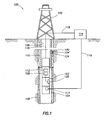
- Figure 1 is a schematic view of a wellsite 100 having an oil rig 102 with a downhole tool 104 suspended into a wellbore 106 therebelow.
- the wellbore 106 has been drilled by a drilling tool (not shown).
- a drilling mud 108 has been pumped into the wellbore 106 and lines a wall thereof.
- a casing 110 has also been positioned in the wellbore 106 and cemented into place therein.
- the downhole tool 104 is shown as a wireline logging tool lowered into the wellbore 106 to take various measurements.
- the downhole tool 104 has a conventional logging device 112 therein that may be provided with various sensors, measurement devices, communication devices, sampling devices and/or other devices for performing wellbore operations.
- a conventional logging device 112 therein that may be provided with various sensors, measurement devices, communication devices, sampling devices and/or other devices for performing wellbore operations.
- the downhole tool 104 may use devices known in the art, such as resistivity or other logging devices, to measure formation properties.
- the downhole tool 104 is operatively connected to a surface unit 114 for communication therebetween.
- the downhole tool 104 may be wired via the wireline 116 as shown and/or wirelessly linked via telemetry devices 117, such as conventional electromagnetic devices known in the art, for passing signals to a surface unit 114 as indicated by communication links 118. Signals may be passed between the downhole tool 104 and the surface unit 114 and/or other locations for communication therebetween.
- the downhole tool 104 is also provided with a fluid sensor 120 for determining downhole fluid parameters.
- the fluid sensor 120 is preferably capable of determining parameters of downhole fluids, such as downhole mud (e.g., oil based), hydrocarbons, water and/or other downhole fluids. Additionally, the fluid sensor 120 is preferably capable of determining parameters of downhole fluids as the downhole tool 104 passes through the wellbore 106. Due to the harsh conditions of the downhole environment, the fluid sensor 120 is preferably positioned on the downhole tool 104 in such a manner that the fluid sensor is capable of receiving fluids as the downhole tool 104 passes through the wellbore 106, and that reduces clogging of such fluids as fluids pass through the fluid sensor 120.
- the fluid sensor 120 is positioned on an outer surface 122 of the downhole tool 104.
- the fluid sensor 120 may be recessed a distance below the outer surface 122 to provide additional protection thereto, or protruded a distance therefrom to access fluid.
- the fluid sensor 120 may also be positioned at various angles as desired.
- the fluid sensor 120 is also depicted as being positioned on production monitoring devices 104'.
- the production monitors 104' may be conventional production monitors as known in the art. These production monitors 104' are typically positioned about the well as shown for monitoring the production of fluids through the wellbore 106.
- the fluid sensors 120 are positioned on an outer surface 124 of one or more of the production monitors 104'.
- the downhole tool 104 is depicted as a wireline tool 104 and a production monitor 104' with the fluid sensor 120 thereon, it will be appreciated that the fluid sensor 120 may be positioned downhole on a variety of one or more tools.
- the fluid sensor 120 may be placed downhole on a drilling, coiled tubing, drill stem tester, production, casing, pipe, or other downhole tool.
- the fluid sensor 120 is preferably positioned about an outer surface of the downhole tool so that fluid may pass therealong for measurement thereof.
- one or more fluid sensors 120 may be positioned at various locations about the wellsite as desired for performing fluid measurement.
- a power source 126 is operatively connected to the fluid sensor 120 for applying an AC voltage thereto at a frequency of between about tens of Hz to a few GHz.
- the power source 126 may be provided by a battery, power supply or other conventional means of providing power. In some cases, the power source 126 may be an existing power source used in the downhole tool.
- the power source 126 may be positioned, for example, in the downhole tool 104 and wired to the fluid sensor 120 for providing power thereto as shown.
- the power source 126 may be provided for use with the fluid sensor 120 and/or other downhole devices.
- the power source 126 may be positioned within the fluid sensor 120 or separate therefrom.
- the fluid sensor 120 may also be wired or wirelessly connected to other features of the downhole tool, such as communication links, processors, power sources or other features thereof.
- FIGS 2A-2E show detailed views of various configurations 120a-e usable as the fluid sensor 120 of Figure 1 .
- Each fluid sensor 120a-e comprises a pair of electrodes 228,229a-e positioned in insulation 230 on a base (or pad) 232.
- Part or all of the base 232 may comprise the insulation 230.
- the base 232 may be adhered to the outer surface 122 of the downhole tool (e.g., 104 and/or 104' in Figure 1 ) using any conventional means.
- the insulation 230 may be adhered to the base 232 using any conventional means.
- the insulation 230 is preferably a material, such as a polymide resin, capable of providing insulation about the electrodes 228,229a-e.
- the insulation 230 may be provided with a thin layer of copper thereon, with a layer of gold applied to the copper to prevent oxidation (not shown).
- the electrodes 228,229a-e may be applied into the insulation 230 in the desired configuration using, for example, printed circuit board technology, wet or dry etching, and/or other conventional electronics construction technique.
- the electrodes 228,229a-e may be any conventional electrode capable of generating current across a fluid.
- a power source e.g., power source 126 of Figure 1
- the electrodes 228,229a-e are combined to form a capacitor for measuring current flowing therebetween.
- the electrodes 228,229a-e are preferably positioned such that capacitances are achieved between the surfaces of the electrodes 228,229a-e as wellbore fluids pass therebetween. As voltage is applied, a current flows out of one of the electrodes that can be measured.
- the current from the electrodes may be used to determine various parameters.
- an AC voltage V is applied between two parallel plates to generate a resultant current I that can be measured at either electrode.
- An impedance generated from the electrodes may consist of two capacitances in parallel, such as the capacitances between the electrodes interfacing with the wellbore fluid and interfacing with the insulation.
- the constant k may be measured empirically, for example, by measuring the impedance V / I between electrodes as a fluid of known impedivity is passed therethrough.
- the constant k may also be calculated from the geometry of the electrodes using conventional methods.
- Data concerning the measured current may be used to determine fluid parameters, such as impedivity, resistivity, impedence, general conductivity, complex conductivity, complex permittivity, tangent delta, and combinations thereof, as well as other parameters of the wellbore fluid.
- the data may be analyzed to determine characteristics of the wellbore fluid, such as the type of fluid (e.g., hydrocarbon, mud, contaminants, etc.)
- a processor e.g., logging device 112 of Figure 1
- the data may be communicated to the surface unit 114 and/or other location for storage and/or analysis. Such analysis may be performed with other inputs, such as historical or measured data about this or other wellsites. Reports and/or other outputs may be generated from the data.
- the data may be used to make decisions and/or adjust operations at the wellsite. In some cases, the data may be fed back to the wellsite for real-time decision making and/or operation.
- the electrodes 228,229a-e of the fluid sensor 120 are configured to optimize measurement of fluid passing therebetween.
- the insulating base is preferably of a small dimension having a surface area of about 1 cm 2 .
- the raised (i.e. arch) electrode fits within the base and has about the same overall dimensions.
- the base electrode is preferably smaller, having a surface are of a few square millimeters.
- Electrodes 229a-e are in a raised configuration relative to electrodes 228 to enable fluid flow therebetween.
- a voltage may be applied across the electrodes 228,229a-e.
- the voltage may be, for example, an AC voltage signal at a frequency of between about 10 Hz and 5 GHz.
- the electrodes 228,229a-e are preferably positioned with a space therebetween, to act as a capacitor with a current flowing thereacross.
- the electrodes are preferably configured for sensitivity to, for example, wellbore mud. The current flowing from either electrode 228,229a-e may be measured as described above.
- the information gathered preferably provides information sufficient to determine various fluid parameters and/or to identify the type of fluid (e.g., hydrocarbon, mud, etc.) This information may be used for further analysis, for example to provide micro-resistivity imaging of the wellbore. The information may also be used to locate and/or characterize reservoirs.
- type of fluid e.g., hydrocarbon, mud, etc.
- This information may be used for further analysis, for example to provide micro-resistivity imaging of the wellbore.
- the information may also be used to locate and/or characterize reservoirs.
- the fluid sensor 120 may be operatively connected to devices for operation therewith. As shown in Figure 2A1 , a downhole sensor 237 may be provided to measure various wellbore parameters. A transceiver 239 may also be provided for communication with the fluid sensor 120. For example, the transceiver 239 may communicate wirelessly with the logging tool 112 (see Figure 1 ). A communication link may also be provided with a wired connection between the fluid sensor 120 and the logging tool 112. The fluid sensor 120 may communicate with the surface unit 114 directly, or via the downhole tool 104.
- FIGS 2A1, 2A2 and 2A3 depict a fluid sensor 120a with a raised arch configuration.
- Electrode 228 is positioned in insulation 230 of base 232.
- Electrode 229a has two anchors 231a at each end thereof. The anchors 231a are positioned in insulation 230 of base 232. In this configuration, the electrode 229a has a raised portion 234a positioned a distance above the base 232 and electrode 228 to define a space 233a therebetween for the flow of fluid therethrough.
- Figure 2A2 is a plan view of the fluid sensor 120a of Figure 2A1 .
- the electrode 228 is preferably positioned underneath a central portion of electrode 229a.
- the length 11 of the electrode 228 is preferably about 5mm 2 or less.
- the length 12 of electrode 229a is preferably about 25mm or less.
- Figure 2A3 shows an elevational view of the fluid sensor 120a of Figure 2A1 .
- a distance d1 is defined in a space 233a between the electrode 228 and the electrode 229a at its highest point as shown. The space between the electrodes in this raised direction is sufficient to prevent clogging, for example, about 2-3 mm.
- a distance d2 is defined between electrode 228 and anchor 231a as shown. Preferably, the distance d1 is smaller by a factor of about two or more than the distance d2, for example, at about 4-6 mm.
- Figures 2B-2E2 depict various embodiments of the fluid sensor 120c-e having a raised portion 234b-e and a base portion 236b-e.
- the fluid sensors 120c-e may include a base 232 comprising insulation 230 as described, for example, with respect to Figure 2A1 , and an electrode 228 positioned in the insulation 230 on base 232 (not shown on Figures 2C1-2E2 ).
- the electrodes 229b-e are operatively connected in the insulation 230 of the base 232 in various raised configurations over electrodes 228 with a space 233b defined therebetween.
- Figure 2B shows an alternate version 120b of the raised arch fluid sensor 120a of Figures 2A1-2A3 .
- This configuration is the same as the fluid sensor 120a, except that electrode 229b has a base portion 236b coupled to the raised portion 234b.
- the base portion 236b is an elliptical loop positioned in insulation 230 of base 232, and encircling electrode 228.
- Raised portion 234b may be anchored to the electrode 229b via anchors 231b.
- the raised portion 234b may be integral with the base portion 236b, or operatively coupled to the base portion 236b and/or electrode 229b via the anchors 231b. As shown in this configuration, the base portion 236b may act in conjunction with or in place of anchor 231b.
- Figures 2C1-2C2 depict top and elevational views, respectively, of a fluid sensor 120c in a raised cross configuration.
- the electrode 229c has an oval portion 236c that forms a loop positioned in insulation 230 of base 232 (not shown), and two raised arches 234c1,c2 operatively connected to the oval base portion 236c.
- the two raised arches 234c1,c2 are operatively connected perpendicular to each other to form a cross as seen in the top view of Figure 2C1 .
- the raised arch 234c1 is depicted as being attached to the oval base portion 236c at the widest part thereof.
- the raised arch 234c2 is depicted as being attached to the oval portion 229c at the longest part thereof.
- the raised arches 234c1,c2 are unitary with each other and base portion 236c.
- a space 233c is defined between the electrodes 229c and 228 as shown in Figure 2C2 .
- Figures 2D1-2D2 depict top and elevational views, respectively, of a fluid sensor 120d in a raised X configuration.
- the electrode 229d has a square base portion 236d that forms a loop positioned in insulation 230 of base 232 (not shown), and two raised arches 234d are operatively connected to the oval base portion 236d.
- the two raised arches 234d connect at a peak to form an X as seen in the top view of Figure 2D1 .
- the raised arches 234d are depicted as being attached to the square base portion 236d at the coners thereof. As shown, the raised arches 234d are unitarily with each other and base portion 236d.
- a space 233d is defined between the electrodes 229d and 228 as shown in Figure 2D2 .
- Figures 2E1-2E2 depict top and elevational views, respectively, of a fluid sensor 120e in a raised grid configuration.
- the electrode 229e has an rectangular base portion 236e positioned in insulation 230 of base 232 (not shown), and multiple raised arches 234e1,e2 operatively connected to the rectangular base portion 236e.
- the two raised arches 234e1,e2 are operatively connected to form a grid as seen in the top view of Figure 2E1 .
- Two raised arches 234e1 are depicted as being attached to the rectangular base portion 236e at the longest part thereof.
- Three raised arches 234e2 are depicted as being attached to a short side of rectangular base portion 236e at the longest part thereof.
- the raised arches 234e1,e2 are unitarily with each other and base portion 236e.
- a space 233e is defined between the electrodes 229e and 228 as shown in Figure 2E2 .
- the base 232 and/or insulation 230 thereon may be of any shape.
- the base 232 is preferably a loop positioned about the electrode 228.
- the shape of the looped base may be elliptical as shown in Figures 2A1-C2 , square as shown in Figures 2D1-2 or rectangular as shown in Figures 2E1-2 .
- the electrode 228 is positioned centrally below the electrode 229b-e.
- Electrode 229b-e is preferably positioned such that portions of the electrode are positioned symmetrically about the electrode 228.
- the fluid sensors 120a-e may be positioned at a desired angle such that the electrodes 228,229a-e are positioned in a desired direction.
- Figure 3 is a flow chart depicting a method (350) of determining at least one parameter of a wellbore fluid.
- the method involved positioning (352) a downhole tool 104 with a fluid sensor 120 thereon into a wellbore 106 (see, e.g., Figure 1 ).
- a downhole fluid 108 is received (354) between electrodes of the fluid sensor 120.
- a voltage is applied (356) across electrodes 228,229a-e of the fluid sensor 120 to generate a current therebetween (see, e.g., Figures 2A-2D ).
- Parameters may be determined (358) from the current generated from the electrodes.
- Data may be collected (360) concerning the wellsite. This data may be data from the fluid sensor 120, the downhole sensor 233, historical or other data. The collected data may be analyzed (362) and reports generated (364). Actions, such as adjusting wellsite operations, may be taken (366) based on the analysis. The steps of the method may be repeated (368) continuously or at discrete locations as the downhole tool 104 is moving through the wellbore. Various combinations of the steps of the method may be performed in a desired order using one or more downhole tools 104 and/or one or more fluid sensors 120.
- the one or more fluid and/or other sensors may be positioned about the wellsite to measure and/or collect data.
Claims (15)
- Fluidsensor (120) zum Bestimmen wenigstens eines Parameters eines Fluids eines Bohrlochs, wobei der Fluidsensor umfasst:eine Grundplatte (232), die insbesondere für das Positionieren in dem Bohrloch ausgelegt ist, wobei die Grundplatte eine Isolation (230) umfasst;eine Grundplattenelektrode (228), die funktional in der Isolation (230) positioniert ist; undeine erhöhte Elektrode (229a-e), die wenigstens einen Grundplattenabschnitt und wenigstens einen erhöhten Abschnitt aufweist, wobei der wenigstens eine Grundplattenabschnitt funktional in der Isolation (230) positioniert ist, wobei der wenigstens eine erhöhte Abschnitt in der Weise in einer Entfernung über der Grundplattenelektrode (228) positioniert ist, dass dazwischen ein Raum für den Durchgang des Bohrlochfluids dadurch definiert ist;wobei eine über die Grundplattenelektrode (228) und die erhöhte Elektrode (229a-e) angelegte Spannung dazwischen einen Strom erzeugt, wodurch wenigstens ein Parameter des Bohrlochfluids bestimmt werden kann.
- Fluidsensor nach Anspruch 1, wobei der wenigstens eine erhöhte Abschnitt einen Bogen umfasst und wobei der wenigstens eine Grundplattenabschnitt ein Paar Verankerungen, jede des Paars von Verankerungen an gegenüberliegenden Enden des Bogens, umfasst.
- Fluidsensor nach Anspruch 2, wobei der wenigstens eine Grundplattenabschnitt um die Grundplattenelektrode eine Schleife bildet.
- Fluidsensor nach Anspruch 1, wobei der wenigstens eine erhöhte Abschnitt mehrere Bögen umfasst und wobei der wenigstens eine Grundplattenabschnitt um die Grundplattenelektrode eine Schleife bildet, wobei die mehreren Bögen in einer Kreuzkonfiguration mit dem Grundplattenabschnitt funktional verbunden sind.
- Fluidsensor nach Anspruch 1, wobei der wenigstens eine erhöhte Abschnitt mehrere Bögen umfasst und wobei der wenigstens eine Grundplattenabschnitt um die Grundplattenelektrode eine Schleife bildet, wobei die mehreren Bögen in einer X-Konfiguration mit dem Grundplattenabschnitt funktional verbunden sind.
- Fluidsensor nach Anspruch 1, wobei der wenigstens eine erhöhte Abschnitt mehrere Bögen umfasst und wobei der wenigstens eine Grundplattenabschnitt um die Grundplattenelektrode eine Schleife bildet, wobei die mehreren Bögen in einer Gitterkonfiguration mit dem Grundplattenabschnitt funktional verbunden sind.
- Fluidsensor nach Anspruch 1, der ferner eine Leistungsquelle zum Bereitstellen der Spannung umfasst.
- Fluidsensor nach Anspruch 1, der ferner einen Prozessor zum Analysieren des Stroms, um den wenigstens einen Fluidparameter zu bestimmen, umfasst.
- Fluidsensor nach Anspruch 1, der ferner wenigstens einen Bohrstellensensor umfasst, der zum Bestimmen wenigstens eines Parameters des Bohrlochs damit funktional verbunden ist.
- Fluidsensor nach Anspruch 1, wobei der wenigstens eine Parameter des Bohrlochfluids die spezifische Impedanz oder der spezifische Widerstand oder die Impedanz oder die allgemeine Leitfähigkeit oder die komplexe Leitfähigkeit oder die komplexe Dielektrizitätskonstante oder der Tangens Delta oder Kombinationen davon ist.
- Fluidsensor nach Anspruch 1, wobei die Grundplatte über ein Bohrlochwerkzeug unter Tage im Bohrloch positioniert werden kann.
- Fluidsensor nach Anspruch 11, wobei das Bohrlochwerkzeug ein Bohrwerkzeug oder ein Seilarbeitswerkzeug oder ein Förderwerkzeug oder ein Überwachungswerkzeug oder ein Fördermonitor oder ein Rohrwendelwerkzeug oder ein Futterrohrwerkzeug oder Kombinationen davon ist.
- Verfahren zum Bestimmen wenigstens eines Parameters eines Fluids in einem Bohrloch, wobei das Verfahren umfasst:Bereitstellen eines Fluidsensors (120), der umfasst:eine Grundplatte (232), die besonders für das Positionieren in dem Bohrloch ausgelegt ist, wobei die Grundplatte eine Isolation (230) umfasst;eine Grundplattenelektrode (228), die funktional in der Isolation (230) positioniert ist; undeine erhöhte Elektrode (229a-e), die wenigstens einen Grundplattenabschnitt und wenigstens einen erhöhten Abschnitt aufweist, wobei der wenigstens eine Grundplattenabschnitt funktional in der Isolation (230) positioniert ist, wobei der wenigstens eine erhöhte Abschnitt in der Weise in einer Entfernung über der Grundplattenelektrode (228) positioniert ist, dass dazwischen ein Raum für den Durchgang des Bohrlochfluids dadurch definiert ist;Positionieren eines Bohrlochwerkzeugs (104) in dem Bohrloch (106) mit dem Fluidsensor daran;Aufnehmen eines Bohrlochfluids zwischen der Grundplattenelektrode (228) und den erhöhten Elektroden (229a-e);Anlegen einer Spannung über das Paar von Elektroden, um einen Strom dazwischen zu erzeugen; undBestimmen des wenigstens eines Fluidparameters aus dem erzeugten Strom.
- Verfahren nach Anspruch 13, das ferner das Analysieren des wenigstens einen Fluidparameters umfasst.
- Verfahren nach Anspruch 14, das ferner das Einstellen wenigstens einer Bohrstellenoperation auf der Grundlage des analysierten wenigstens einen Fluidparameters umfasst.
Priority Applications (5)
| Application Number | Priority Date | Filing Date | Title |
|---|---|---|---|
| EP10290084.2A EP2362210B1 (de) | 2010-02-19 | 2010-02-19 | Flüssigkeitssensor und Verfahren zu dessen Verwendung |
| PCT/EP2011/000555 WO2011101099A1 (en) | 2010-02-19 | 2011-02-07 | Fluid sensor and method of using same |
| MX2012009657A MX2012009657A (es) | 2010-02-19 | 2011-02-07 | Sensor de fluido y método de uso del mismo. |
| US13/579,942 US8893782B2 (en) | 2010-02-19 | 2011-02-07 | Fluid sensor and method of using same |
| BR112012020913A BR112012020913A2 (pt) | 2010-02-19 | 2011-02-07 | sensor de fluido para a determinação de pelo menos um parâmetro de um fluido de um poço, e método para determinar pelo menos um parâmetro de um fluido à um furo de poço |
Applications Claiming Priority (1)
| Application Number | Priority Date | Filing Date | Title |
|---|---|---|---|
| EP10290084.2A EP2362210B1 (de) | 2010-02-19 | 2010-02-19 | Flüssigkeitssensor und Verfahren zu dessen Verwendung |
Publications (2)
| Publication Number | Publication Date |
|---|---|
| EP2362210A1 EP2362210A1 (de) | 2011-08-31 |
| EP2362210B1 true EP2362210B1 (de) | 2015-01-07 |
Family
ID=42340483
Family Applications (1)
| Application Number | Title | Priority Date | Filing Date |
|---|---|---|---|
| EP10290084.2A Not-in-force EP2362210B1 (de) | 2010-02-19 | 2010-02-19 | Flüssigkeitssensor und Verfahren zu dessen Verwendung |
Country Status (5)
| Country | Link |
|---|---|
| US (1) | US8893782B2 (de) |
| EP (1) | EP2362210B1 (de) |
| BR (1) | BR112012020913A2 (de) |
| MX (1) | MX2012009657A (de) |
| WO (1) | WO2011101099A1 (de) |
Cited By (1)
| Publication number | Priority date | Publication date | Assignee | Title |
|---|---|---|---|---|
| US9678239B2 (en) | 2010-11-15 | 2017-06-13 | Schlumberger Technology Corporation | System and method for imaging properties of subterranean formations |
Families Citing this family (8)
| Publication number | Priority date | Publication date | Assignee | Title |
|---|---|---|---|---|
| US8776878B2 (en) | 2008-10-31 | 2014-07-15 | Schlumberger Technology Corporation | Sensor for determining downhole parameters and methods for using same |
| EP2182391B1 (de) | 2008-10-31 | 2012-02-08 | Services Pétroliers Schlumberger | Gerät zur Abbildung einer Bohrlochumgebung |
| DE102010060465A1 (de) * | 2010-11-09 | 2012-05-10 | Harald Riegel | Verfahren zur Kalibrierung einer Leitfähigkeitsmesszelle |
| EP2541284A1 (de) | 2011-05-11 | 2013-01-02 | Services Pétroliers Schlumberger | System und Verfahren zur Erzeugung von flüssigkeitskompensierten Bohrlochparametern |
| US20130265063A1 (en) * | 2012-04-06 | 2013-10-10 | Exxonmobil Research And Engineering Company | Method and apparatus for detecting the presence of water in a current of liquid hydrocarbons |
| US9579765B2 (en) * | 2012-09-13 | 2017-02-28 | General Electric Technology Gmbh | Cleaning and grinding of sulfite sensor head |
| US9429012B2 (en) * | 2013-05-07 | 2016-08-30 | Saudi Arabian Oil Company | Downhole salinity measurement |
| US9677394B2 (en) | 2013-06-28 | 2017-06-13 | Schlumberger Technology Corporation | Downhole fluid sensor with conductive shield and method of using same |
Family Cites Families (13)
| Publication number | Priority date | Publication date | Assignee | Title |
|---|---|---|---|---|
| US3449640A (en) * | 1967-03-24 | 1969-06-10 | Itt | Simplified stacked semiconductor device |
| DE3316837C2 (de) | 1983-05-07 | 1986-06-26 | Dornier System Gmbh, 7990 Friedrichshafen | Einrichtung zur Erzeugung von Stoßwellen mittels einer Funkenstrecke für die berührungsfreie Zertrümmerung von Konkrementen in Körpern von Lebewesen |
| JP3094170B2 (ja) | 1991-03-27 | 2000-10-03 | 株式会社小松製作所 | 金属粒子検出センサの電極構造 |
| US5736637A (en) * | 1996-05-15 | 1998-04-07 | Western Atlas International, Inc. | Downhole multiphase flow sensor |
| DE19649366C2 (de) * | 1996-11-28 | 1999-05-27 | Siemens Automotive Sa | Mikrosensor zur Flüssigkeitsanalyse, insbesondere von Alkohol-Benzin-Gemischen |
| US6377052B1 (en) * | 1999-11-03 | 2002-04-23 | Eaton Corporation | Monitoring fluid condition through an aperture |
| CA2329672C (en) | 2000-12-27 | 2009-12-22 | Donald W. Kirk | Bifurcated electrode of use in electrolytic cells |
| US6801039B2 (en) | 2002-05-09 | 2004-10-05 | Baker Hughes Incorporated | Apparatus and method for measuring mud resistivity using a defocused electrode system |
| EP1439388A1 (de) | 2003-01-20 | 2004-07-21 | Ecole Polytechnique Fédérale de Lausanne (EPFL) | Vorrichtung zur Messung der Qualität und/oder der Zersetzung einer Flüssigkeit, insbesondere von Speiseöl |
| US7234519B2 (en) * | 2003-04-08 | 2007-06-26 | Halliburton Energy Services, Inc. | Flexible piezoelectric for downhole sensing, actuation and health monitoring |
| US7258005B2 (en) | 2004-02-06 | 2007-08-21 | David Scott Nyce | Isolated capacitive fluid level sensor |
| US7520160B1 (en) | 2007-10-04 | 2009-04-21 | Schlumberger Technology Corporation | Electrochemical sensor |
| US8027794B2 (en) | 2008-02-11 | 2011-09-27 | Schlumberger Technology Corporaton | System and method for measuring properties of liquid in multiphase mixtures |
-
2010
- 2010-02-19 EP EP10290084.2A patent/EP2362210B1/de not_active Not-in-force
-
2011
- 2011-02-07 WO PCT/EP2011/000555 patent/WO2011101099A1/en active Application Filing
- 2011-02-07 US US13/579,942 patent/US8893782B2/en not_active Expired - Fee Related
- 2011-02-07 BR BR112012020913A patent/BR112012020913A2/pt active Search and Examination
- 2011-02-07 MX MX2012009657A patent/MX2012009657A/es active IP Right Grant
Cited By (1)
| Publication number | Priority date | Publication date | Assignee | Title |
|---|---|---|---|---|
| US9678239B2 (en) | 2010-11-15 | 2017-06-13 | Schlumberger Technology Corporation | System and method for imaging properties of subterranean formations |
Also Published As
| Publication number | Publication date |
|---|---|
| US8893782B2 (en) | 2014-11-25 |
| MX2012009657A (es) | 2012-10-05 |
| BR112012020913A2 (pt) | 2016-05-03 |
| EP2362210A1 (de) | 2011-08-31 |
| US20130037263A1 (en) | 2013-02-14 |
| WO2011101099A1 (en) | 2011-08-25 |
Similar Documents
| Publication | Publication Date | Title |
|---|---|---|
| EP2362210B1 (de) | Flüssigkeitssensor und Verfahren zu dessen Verwendung | |
| EP2498105B1 (de) | Vorrichtung und Verfahren zum Messen der elektrischen Eigenschaften einer unterirdischen Formation | |
| US8776878B2 (en) | Sensor for determining downhole parameters and methods for using same | |
| US9360444B2 (en) | Fluid sensor and method of using same | |
| CA2834079C (en) | Apparatus and method for multi-component wellbore electric field measurements using capacitive sensors | |
| US8302687B2 (en) | Apparatus for measuring streaming potentials and determining earth formation characteristics | |
| US7388380B2 (en) | While-drilling apparatus for measuring streaming potentials and determining earth formation characteristics and other useful information | |
| US7466136B2 (en) | While-drilling methodology for determining earth formation characteristics and other useful information based upon streaming potential measurements | |
| US20150260874A1 (en) | System and Method for Imaging Subterranean Formations | |
| US8564315B2 (en) | Downhole corrosion monitoring | |
| US20200209193A1 (en) | Systems and methods for obtaining downhole fluid properties | |
| US20220381937A1 (en) | System and method for characterizing subterranean formations | |
| US20050280419A1 (en) | While-drilling apparatus for measuring streaming potentials and determining earth formation characteristics | |
| US9863239B2 (en) | Selecting transmission frequency based on formation properties | |
| CA2793786A1 (en) | Methods and apparatus for measuring streaming potentials and determining earth formation characteristics | |
| US20170285212A1 (en) | System and method for measuring downhole parameters |
Legal Events
| Date | Code | Title | Description |
|---|---|---|---|
| PUAI | Public reference made under article 153(3) epc to a published international application that has entered the european phase |
Free format text: ORIGINAL CODE: 0009012 |
|
| AK | Designated contracting states |
Kind code of ref document: A1 Designated state(s): AT BE BG CH CY CZ DE DK EE ES FI FR GB GR HR HU IE IS IT LI LT LU LV MC MK MT NL NO PL PT RO SE SI SK SM TR |
|
| AX | Request for extension of the european patent |
Extension state: AL BA RS |
|
| 17P | Request for examination filed |
Effective date: 20111222 |
|
| GRAP | Despatch of communication of intention to grant a patent |
Free format text: ORIGINAL CODE: EPIDOSNIGR1 |
|
| INTG | Intention to grant announced |
Effective date: 20140911 |
|
| GRAS | Grant fee paid |
Free format text: ORIGINAL CODE: EPIDOSNIGR3 |
|
| GRAA | (expected) grant |
Free format text: ORIGINAL CODE: 0009210 |
|
| AK | Designated contracting states |
Kind code of ref document: B1 Designated state(s): AT BE BG CH CY CZ DE DK EE ES FI FR GB GR HR HU IE IS IT LI LT LU LV MC MK MT NL NO PL PT RO SE SI SK SM TR |
|
| REG | Reference to a national code |
Ref country code: GB Ref legal event code: FG4D |
|
| REG | Reference to a national code |
Ref country code: CH Ref legal event code: EP |
|
| REG | Reference to a national code |
Ref country code: IE Ref legal event code: FG4D |
|
| REG | Reference to a national code |
Ref country code: AT Ref legal event code: REF Ref document number: 706055 Country of ref document: AT Kind code of ref document: T Effective date: 20150215 |
|
| REG | Reference to a national code |
Ref country code: DE Ref legal event code: R096 Ref document number: 602010021576 Country of ref document: DE Effective date: 20150219 |
|
| REG | Reference to a national code |
Ref country code: NL Ref legal event code: VDEP Effective date: 20150107 |
|
| REG | Reference to a national code |
Ref country code: AT Ref legal event code: MK05 Ref document number: 706055 Country of ref document: AT Kind code of ref document: T Effective date: 20150107 |
|
| REG | Reference to a national code |
Ref country code: LT Ref legal event code: MG4D |
|
| PG25 | Lapsed in a contracting state [announced via postgrant information from national office to epo] |
Ref country code: BE Free format text: LAPSE BECAUSE OF NON-PAYMENT OF DUE FEES Effective date: 20150228 |
|
| PG25 | Lapsed in a contracting state [announced via postgrant information from national office to epo] |
Ref country code: ES Free format text: LAPSE BECAUSE OF FAILURE TO SUBMIT A TRANSLATION OF THE DESCRIPTION OR TO PAY THE FEE WITHIN THE PRESCRIBED TIME-LIMIT Effective date: 20150107 Ref country code: SE Free format text: LAPSE BECAUSE OF FAILURE TO SUBMIT A TRANSLATION OF THE DESCRIPTION OR TO PAY THE FEE WITHIN THE PRESCRIBED TIME-LIMIT Effective date: 20150107 Ref country code: NO Free format text: LAPSE BECAUSE OF FAILURE TO SUBMIT A TRANSLATION OF THE DESCRIPTION OR TO PAY THE FEE WITHIN THE PRESCRIBED TIME-LIMIT Effective date: 20150407 Ref country code: FI Free format text: LAPSE BECAUSE OF FAILURE TO SUBMIT A TRANSLATION OF THE DESCRIPTION OR TO PAY THE FEE WITHIN THE PRESCRIBED TIME-LIMIT Effective date: 20150107 Ref country code: HR Free format text: LAPSE BECAUSE OF FAILURE TO SUBMIT A TRANSLATION OF THE DESCRIPTION OR TO PAY THE FEE WITHIN THE PRESCRIBED TIME-LIMIT Effective date: 20150107 Ref country code: BG Free format text: LAPSE BECAUSE OF FAILURE TO SUBMIT A TRANSLATION OF THE DESCRIPTION OR TO PAY THE FEE WITHIN THE PRESCRIBED TIME-LIMIT Effective date: 20150407 Ref country code: LT Free format text: LAPSE BECAUSE OF FAILURE TO SUBMIT A TRANSLATION OF THE DESCRIPTION OR TO PAY THE FEE WITHIN THE PRESCRIBED TIME-LIMIT Effective date: 20150107 |
|
| PG25 | Lapsed in a contracting state [announced via postgrant information from national office to epo] |
Ref country code: PL Free format text: LAPSE BECAUSE OF FAILURE TO SUBMIT A TRANSLATION OF THE DESCRIPTION OR TO PAY THE FEE WITHIN THE PRESCRIBED TIME-LIMIT Effective date: 20150107 Ref country code: LV Free format text: LAPSE BECAUSE OF FAILURE TO SUBMIT A TRANSLATION OF THE DESCRIPTION OR TO PAY THE FEE WITHIN THE PRESCRIBED TIME-LIMIT Effective date: 20150107 Ref country code: NL Free format text: LAPSE BECAUSE OF FAILURE TO SUBMIT A TRANSLATION OF THE DESCRIPTION OR TO PAY THE FEE WITHIN THE PRESCRIBED TIME-LIMIT Effective date: 20150107 Ref country code: AT Free format text: LAPSE BECAUSE OF FAILURE TO SUBMIT A TRANSLATION OF THE DESCRIPTION OR TO PAY THE FEE WITHIN THE PRESCRIBED TIME-LIMIT Effective date: 20150107 Ref country code: GR Free format text: LAPSE BECAUSE OF FAILURE TO SUBMIT A TRANSLATION OF THE DESCRIPTION OR TO PAY THE FEE WITHIN THE PRESCRIBED TIME-LIMIT Effective date: 20150408 Ref country code: IS Free format text: LAPSE BECAUSE OF FAILURE TO SUBMIT A TRANSLATION OF THE DESCRIPTION OR TO PAY THE FEE WITHIN THE PRESCRIBED TIME-LIMIT Effective date: 20150507 |
|
| REG | Reference to a national code |
Ref country code: CH Ref legal event code: PL |
|
| REG | Reference to a national code |
Ref country code: DE Ref legal event code: R097 Ref document number: 602010021576 Country of ref document: DE |
|
| PG25 | Lapsed in a contracting state [announced via postgrant information from national office to epo] |
Ref country code: DK Free format text: LAPSE BECAUSE OF FAILURE TO SUBMIT A TRANSLATION OF THE DESCRIPTION OR TO PAY THE FEE WITHIN THE PRESCRIBED TIME-LIMIT Effective date: 20150107 Ref country code: CH Free format text: LAPSE BECAUSE OF NON-PAYMENT OF DUE FEES Effective date: 20150228 Ref country code: CZ Free format text: LAPSE BECAUSE OF FAILURE TO SUBMIT A TRANSLATION OF THE DESCRIPTION OR TO PAY THE FEE WITHIN THE PRESCRIBED TIME-LIMIT Effective date: 20150107 Ref country code: MC Free format text: LAPSE BECAUSE OF FAILURE TO SUBMIT A TRANSLATION OF THE DESCRIPTION OR TO PAY THE FEE WITHIN THE PRESCRIBED TIME-LIMIT Effective date: 20150107 Ref country code: EE Free format text: LAPSE BECAUSE OF FAILURE TO SUBMIT A TRANSLATION OF THE DESCRIPTION OR TO PAY THE FEE WITHIN THE PRESCRIBED TIME-LIMIT Effective date: 20150107 Ref country code: LI Free format text: LAPSE BECAUSE OF NON-PAYMENT OF DUE FEES Effective date: 20150228 Ref country code: RO Free format text: LAPSE BECAUSE OF FAILURE TO SUBMIT A TRANSLATION OF THE DESCRIPTION OR TO PAY THE FEE WITHIN THE PRESCRIBED TIME-LIMIT Effective date: 20150107 Ref country code: SK Free format text: LAPSE BECAUSE OF FAILURE TO SUBMIT A TRANSLATION OF THE DESCRIPTION OR TO PAY THE FEE WITHIN THE PRESCRIBED TIME-LIMIT Effective date: 20150107 |
|
| PLBE | No opposition filed within time limit |
Free format text: ORIGINAL CODE: 0009261 |
|
| STAA | Information on the status of an ep patent application or granted ep patent |
Free format text: STATUS: NO OPPOSITION FILED WITHIN TIME LIMIT |
|
| REG | Reference to a national code |
Ref country code: IE Ref legal event code: MM4A |
|
| REG | Reference to a national code |
Ref country code: FR Ref legal event code: ST Effective date: 20151030 |
|
| 26N | No opposition filed |
Effective date: 20151008 |
|
| PG25 | Lapsed in a contracting state [announced via postgrant information from national office to epo] |
Ref country code: IT Free format text: LAPSE BECAUSE OF FAILURE TO SUBMIT A TRANSLATION OF THE DESCRIPTION OR TO PAY THE FEE WITHIN THE PRESCRIBED TIME-LIMIT Effective date: 20150107 |
|
| PG25 | Lapsed in a contracting state [announced via postgrant information from national office to epo] |
Ref country code: IE Free format text: LAPSE BECAUSE OF NON-PAYMENT OF DUE FEES Effective date: 20150219 |
|
| PG25 | Lapsed in a contracting state [announced via postgrant information from national office to epo] |
Ref country code: SI Free format text: LAPSE BECAUSE OF FAILURE TO SUBMIT A TRANSLATION OF THE DESCRIPTION OR TO PAY THE FEE WITHIN THE PRESCRIBED TIME-LIMIT Effective date: 20150107 Ref country code: FR Free format text: LAPSE BECAUSE OF NON-PAYMENT OF DUE FEES Effective date: 20150309 |
|
| PGFP | Annual fee paid to national office [announced via postgrant information from national office to epo] |
Ref country code: DE Payment date: 20160216 Year of fee payment: 7 |
|
| PG25 | Lapsed in a contracting state [announced via postgrant information from national office to epo] |
Ref country code: BE Free format text: LAPSE BECAUSE OF FAILURE TO SUBMIT A TRANSLATION OF THE DESCRIPTION OR TO PAY THE FEE WITHIN THE PRESCRIBED TIME-LIMIT Effective date: 20150107 |
|
| PGFP | Annual fee paid to national office [announced via postgrant information from national office to epo] |
Ref country code: GB Payment date: 20160217 Year of fee payment: 7 |
|
| PG25 | Lapsed in a contracting state [announced via postgrant information from national office to epo] |
Ref country code: MT Free format text: LAPSE BECAUSE OF FAILURE TO SUBMIT A TRANSLATION OF THE DESCRIPTION OR TO PAY THE FEE WITHIN THE PRESCRIBED TIME-LIMIT Effective date: 20150107 |
|
| PG25 | Lapsed in a contracting state [announced via postgrant information from national office to epo] |
Ref country code: SM Free format text: LAPSE BECAUSE OF FAILURE TO SUBMIT A TRANSLATION OF THE DESCRIPTION OR TO PAY THE FEE WITHIN THE PRESCRIBED TIME-LIMIT Effective date: 20150107 Ref country code: HU Free format text: LAPSE BECAUSE OF FAILURE TO SUBMIT A TRANSLATION OF THE DESCRIPTION OR TO PAY THE FEE WITHIN THE PRESCRIBED TIME-LIMIT; INVALID AB INITIO Effective date: 20100219 |
|
| PG25 | Lapsed in a contracting state [announced via postgrant information from national office to epo] |
Ref country code: CY Free format text: LAPSE BECAUSE OF FAILURE TO SUBMIT A TRANSLATION OF THE DESCRIPTION OR TO PAY THE FEE WITHIN THE PRESCRIBED TIME-LIMIT Effective date: 20150107 |
|
| PG25 | Lapsed in a contracting state [announced via postgrant information from national office to epo] |
Ref country code: PT Free format text: LAPSE BECAUSE OF FAILURE TO SUBMIT A TRANSLATION OF THE DESCRIPTION OR TO PAY THE FEE WITHIN THE PRESCRIBED TIME-LIMIT Effective date: 20150507 |
|
| PG25 | Lapsed in a contracting state [announced via postgrant information from national office to epo] |
Ref country code: TR Free format text: LAPSE BECAUSE OF FAILURE TO SUBMIT A TRANSLATION OF THE DESCRIPTION OR TO PAY THE FEE WITHIN THE PRESCRIBED TIME-LIMIT Effective date: 20150107 |
|
| REG | Reference to a national code |
Ref country code: DE Ref legal event code: R119 Ref document number: 602010021576 Country of ref document: DE |
|
| GBPC | Gb: european patent ceased through non-payment of renewal fee |
Effective date: 20170219 |
|
| PG25 | Lapsed in a contracting state [announced via postgrant information from national office to epo] |
Ref country code: LU Free format text: LAPSE BECAUSE OF NON-PAYMENT OF DUE FEES Effective date: 20150219 |
|
| PG25 | Lapsed in a contracting state [announced via postgrant information from national office to epo] |
Ref country code: DE Free format text: LAPSE BECAUSE OF NON-PAYMENT OF DUE FEES Effective date: 20170901 |
|
| PG25 | Lapsed in a contracting state [announced via postgrant information from national office to epo] |
Ref country code: GB Free format text: LAPSE BECAUSE OF NON-PAYMENT OF DUE FEES Effective date: 20170219 |
|
| PG25 | Lapsed in a contracting state [announced via postgrant information from national office to epo] |
Ref country code: MK Free format text: LAPSE BECAUSE OF FAILURE TO SUBMIT A TRANSLATION OF THE DESCRIPTION OR TO PAY THE FEE WITHIN THE PRESCRIBED TIME-LIMIT Effective date: 20150107 |