EP2362091A1 - Schwingungsdämpfsystem für Rotorblätter - Google Patents
Schwingungsdämpfsystem für Rotorblätter Download PDFInfo
- Publication number
- EP2362091A1 EP2362091A1 EP10167870A EP10167870A EP2362091A1 EP 2362091 A1 EP2362091 A1 EP 2362091A1 EP 10167870 A EP10167870 A EP 10167870A EP 10167870 A EP10167870 A EP 10167870A EP 2362091 A1 EP2362091 A1 EP 2362091A1
- Authority
- EP
- European Patent Office
- Prior art keywords
- rotor blade
- outer part
- wind turbine
- rotor
- vibration damping
- Prior art date
- Legal status (The legal status is an assumption and is not a legal conclusion. Google has not performed a legal analysis and makes no representation as to the accuracy of the status listed.)
- Withdrawn
Links
- 238000013016 damping Methods 0.000 title claims abstract description 24
- 230000003213 activating effect Effects 0.000 claims description 4
- 239000002520 smart material Substances 0.000 claims description 2
- 230000010355 oscillation Effects 0.000 description 13
- 230000008878 coupling Effects 0.000 description 1
- 238000010168 coupling process Methods 0.000 description 1
- 238000005859 coupling reaction Methods 0.000 description 1
- 230000000694 effects Effects 0.000 description 1
- 238000005516 engineering process Methods 0.000 description 1
- 230000005484 gravity Effects 0.000 description 1
- 238000010248 power generation Methods 0.000 description 1
Images


Classifications
-
- F—MECHANICAL ENGINEERING; LIGHTING; HEATING; WEAPONS; BLASTING
- F03—MACHINES OR ENGINES FOR LIQUIDS; WIND, SPRING, OR WEIGHT MOTORS; PRODUCING MECHANICAL POWER OR A REACTIVE PROPULSIVE THRUST, NOT OTHERWISE PROVIDED FOR
- F03D—WIND MOTORS
- F03D1/00—Wind motors with rotation axis substantially parallel to the air flow entering the rotor
- F03D1/06—Rotors
- F03D1/0608—Rotors characterised by their aerodynamic shape
-
- F—MECHANICAL ENGINEERING; LIGHTING; HEATING; WEAPONS; BLASTING
- F05—INDEXING SCHEMES RELATING TO ENGINES OR PUMPS IN VARIOUS SUBCLASSES OF CLASSES F01-F04
- F05B—INDEXING SCHEME RELATING TO WIND, SPRING, WEIGHT, INERTIA OR LIKE MOTORS, TO MACHINES OR ENGINES FOR LIQUIDS COVERED BY SUBCLASSES F03B, F03D AND F03G
- F05B2260/00—Function
- F05B2260/96—Preventing, counteracting or reducing vibration or noise
-
- Y—GENERAL TAGGING OF NEW TECHNOLOGICAL DEVELOPMENTS; GENERAL TAGGING OF CROSS-SECTIONAL TECHNOLOGIES SPANNING OVER SEVERAL SECTIONS OF THE IPC; TECHNICAL SUBJECTS COVERED BY FORMER USPC CROSS-REFERENCE ART COLLECTIONS [XRACs] AND DIGESTS
- Y02—TECHNOLOGIES OR APPLICATIONS FOR MITIGATION OR ADAPTATION AGAINST CLIMATE CHANGE
- Y02E—REDUCTION OF GREENHOUSE GAS [GHG] EMISSIONS, RELATED TO ENERGY GENERATION, TRANSMISSION OR DISTRIBUTION
- Y02E10/00—Energy generation through renewable energy sources
- Y02E10/70—Wind energy
- Y02E10/72—Wind turbines with rotation axis in wind direction
Definitions
- the present invention relates to a vibration damping system, in particular to a vibration damping system for a wind turbine, said wind turbine comprising a tower, a nacelle on top of said tower, a rotor having a plurality of rotor blades, said rotor blades having a length of more than 35 metres and preferably a length of more than 45 metres, where said rotor blades at a root end are mounted to a hub fixed to a main shaft, said main shaft being mounted in bearings substantially horizontal in said nacelle, where said rotor blades have a pressure side, a suction side, a leading edge and a trailing edge, and further have an outer part comprising a tip end extending away from said hub.
- the individual rotor blades are rotated, at the interface between the hub and the root end of the blade, more or less about their axis of length in such a manner that the leading edge or in some designs the trailing edge of the rotor blades also is facing up against the wind. This is normally done by using the pitch bearing system or the active stall bearing system that will be used to control the rotor blade during normal operation at wind speeds where the wind turbine can produce power.
- the rotor blades When the rotor blades are pointed with the leading edge or the trailing edge against the wind, the rotor blades can have a tendency to start vibrating or oscillating in the edgewise direction, also known as the chordwise direction, under influence of the high wind speed. Such a vibration or oscillation can also occur under approximately +-15 degrees angle of attack (stall induced vibrations) or by an angle of attack of approximately +-90 degrees (vortex shedding).
- EP 1 019 631 B1 From EP 1 019 631 B1 it is known to shape the rotor blades in a curved manner. This shape is necessary to prevent the rotor blade from hitting the tower of the wind turbine when the rotor blade during use is deflected by the wind.
- the rotor blades described in this document are described as so flexible that when experiencing high wind speeds the rotor blades will be straightened out or even have a slightly rearward bend towards the tower. This is due to the centrifugal forces acting on the rotor blade during rotation and of course also due to the pressure from the wind.
- EP 1 019 631 B1 is thus disclosing very flexible rotor blades, where the stiffness is designed to be just high enough to let the rotor blade straighten out at high wind speeds.
- the shape of the rotor blade and also the stiffness is designed with one specific goal, and that is to prevent the tip of the blade to come into contact with the tower at high wind speeds while the wind turbine is running.
- Another issue in EP 1 019 631 B1 is the aesthetical appearance of the wind turbine, where it very important that the wind turbine has an overall appearance with a rotor, where the blades are more or less straight and situated in a flat rotor plane.
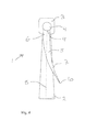
- the invention relates to a vibration damping system for a wind turbine, where the wind turbine comprises a plurality of rotor blades each with an outer part, where said rotor blades at, at least a part of said outer part, have one or more straight or curved centrelines, said outer part being located in an offset position relative to a straight main centre line, said straight main centre line having a point of origin in the centre of said root end of said rotor blade, said main centre line being mainly perpendicular to said root end.
- the rotor blade has an inner part with a straight main centre line and an outer part with one or more straight or curved centre lines, as the outer part can be with an angle to the inner part or it can be curved in relation to the inner part.
- This situation where edgewise oscillations are coupled to the flapwise side of the structure can be reached by having at least a part of said outer part of a rotor blade located in an offset position in the pressure side direction of said rotor blade. Then said blade will have an overall shape where the outer part and end of the blade is in front of the straight main centre line, having a larger distance to the tower, when the rotor blade is active and the wind turbine is running.
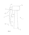
- the vibration damping system for a wind turbine has at least a part of said outer part of a rotor blade located in an offset position in the suction side direction of said rotor blade.
- the outer part of the rotor blade will have a smaller distance to the tower than if the blade was straight as the main centre line.
- the vibration damping system for a wind turbine has at least a part of said outer part of a rotor blade located in an offset position relative to the leading edge and to the trailing edge of said rotor blade but in the same plane as the rest of the rotor blade.
- the outer part of the rotor blade will thus be with a swept forward or backward design.
- a vibration damping system for a wind turbine according to the invention can have at least a part of said outer part of a rotor blade located in an offset position, said offset position being any possible combination of the offset positions described above.
- the rotor blade can thus be with an outer part that is curved or angled in the windward direction and at the same time swept back in relation to the rotational direction of the rotor.
- the rotor blade as described can be curved or angled in one or more sections in the direction towards the tower and still be with a swept back tip end.
- the damper is so to say incorporated in the structure and as such it can not be seen at as a specific part of the rotor blade but merely as a integrated part and feature of a rotor blade where a part of the outer part is offset in relation to the inner part of the rotor blade.
- the rotor blade can, as mentioned above, be designed in a variety of different shape combinations. It can be partial curved, partial straight in the windward, in the leeward directions, but also in the plane described by the rotor blades straight main centre lines and the rotor blade can of course have the shape of any combination thereof.
- a vibration damping system for a wind turbine according to the invention can be with an outer part of the rotor blade, which has a length of approximately 1%, 5%, 10%, 15%, 20%, 25% or 30% of the total length of the rotor blade. Said outer part of the rotor blade being defined as the outer part of the rotor blade where the centre line is not congruent with the straight main centre line.
- said outer part of the rotor blade has a length in the range of 15 to 20% of the total length of the rotor blade.
- said outer part of the rotor blade has an offset distance in the interval between 1 to 10%, more preferably between 2 to 5% of the total length of the rotor blade. Said offset can be in the windward or in the leeward direction, it can be in back or front swept direction or in any combination thereof.
- a vibration damping system for a wind turbine according to the invention can be with one or more rotor blades having means that when activated will deform the rotor blade into a non-straight shape and thus offset the outer part.
- Such means can be activated during stand still of the wind turbine and in situations where there is a risk of harmful oscillation of the rotor blade.
- Such means can be mechanical means, e.g. in the shape of a mechanism connected to the interior of the outer part of the rotor blade, said mechanism further has means for activating and deactivating to change the offset of the outer part of said rotor blade.
- Another solution for said means is to use electronic means in the shape of smart materials, e.g. such as piezoelectric elements connected to the interior or to the exterior of the outer part of the rotor blade, said electronic means has activating and deactivating means to change the offset of the outer part of said rotor blade.
- electronic means in the shape of smart materials, e.g. such as piezoelectric elements connected to the interior or to the exterior of the outer part of the rotor blade, said electronic means has activating and deactivating means to change the offset of the outer part of said rotor blade.
- a stationary structural part installed in the rotor blade or on the surface of the rotor blade, where said stationary structural part is more or less rigid and thus will force the rotor blade to stay in the non-straight shape with an offset outer part.
- Such a structural part can e.g. be retrofitted inside already existing rotor blades on wind turbines experiencing problems with rotor blades that will oscillate in the edgewise direction during stand still at high wind speed.
Priority Applications (1)
| Application Number | Priority Date | Filing Date | Title |
|---|---|---|---|
| EP10167870A EP2362091A1 (de) | 2010-06-30 | 2010-06-30 | Schwingungsdämpfsystem für Rotorblätter |
Applications Claiming Priority (1)
| Application Number | Priority Date | Filing Date | Title |
|---|---|---|---|
| EP10167870A EP2362091A1 (de) | 2010-06-30 | 2010-06-30 | Schwingungsdämpfsystem für Rotorblätter |
Publications (1)
| Publication Number | Publication Date |
|---|---|
| EP2362091A1 true EP2362091A1 (de) | 2011-08-31 |
Family
ID=43254341
Family Applications (1)
| Application Number | Title | Priority Date | Filing Date |
|---|---|---|---|
| EP10167870A Withdrawn EP2362091A1 (de) | 2010-06-30 | 2010-06-30 | Schwingungsdämpfsystem für Rotorblätter |
Country Status (1)
| Country | Link |
|---|---|
| EP (1) | EP2362091A1 (de) |
Cited By (7)
| Publication number | Priority date | Publication date | Assignee | Title |
|---|---|---|---|---|
| CN103104415A (zh) * | 2011-11-04 | 2013-05-15 | 远景能源(江苏)有限公司 | 具有附加转子转动惯量的风力涡轮机及其控制方法 |
| US9074581B2 (en) | 2012-06-12 | 2015-07-07 | General Electric Company | Cone angle insert for wind turbine rotor |
| US9109578B2 (en) | 2012-06-12 | 2015-08-18 | General Electric Company | Root extender for a wind turbine rotor blade |
| EP3130799A4 (de) * | 2014-03-28 | 2017-04-12 | The Chugoku Electric Power Co., Inc. | Windturbinenschaufel und windkraftgenerator damit |
| JP2017520703A (ja) * | 2013-11-15 | 2017-07-27 | ユニヴァーシティ オブ ワシントン | 換気排気のためのエネルギー回収システム、ならびに関連する装置及び方法 |
| CN112983750A (zh) * | 2019-12-13 | 2021-06-18 | 中车株洲电力机车研究所有限公司 | 一种风电机组叶片安装错位诊断方法及装置 |
| US11867156B2 (en) | 2019-09-18 | 2024-01-09 | General Electric Company | System and method for mitigating vortex-shedding vibrations or stall-induced vibrations on rotor blade of a wind turbine during standstill |
Citations (8)
| Publication number | Priority date | Publication date | Assignee | Title |
|---|---|---|---|---|
| EP0955461A2 (de) | 1998-05-04 | 1999-11-10 | Husumer Schiffswerft Inh. Gebrüder Kröger GmbH & Co.KG | Rotorblattsatz für Windkraftanlage |
| EP1019631A1 (de) * | 1997-09-04 | 2000-07-19 | Lm Glasfiber A/S | Rotor für eine windturbine und deren flügel |
| DE19963252A1 (de) * | 1999-12-17 | 2001-07-12 | Lutz Schulze | Längsachsial verändertes Rotorblatt zur Erhöhung der Rotorleistung für HA-Windturbinen |
| WO2003054388A1 (en) | 2001-12-20 | 2003-07-03 | General Electric Company | Wind turbine in parked position |
| US20040067134A1 (en) * | 2002-10-08 | 2004-04-08 | Beauchamp Charles H. | Dynamically reconfigurable wind turbine blade assembly |
| WO2006133715A1 (en) * | 2005-06-17 | 2006-12-21 | Lm Glasfiber A/S | A blade with hinged blade tip |
| EP1850001A2 (de) * | 2006-04-27 | 2007-10-31 | Daubner & Stommel GbR Bau-Werk-Planung | Verfahren zum Betreiben einer Windenergieanlage |
| EP2169217A1 (de) * | 2007-02-28 | 2010-03-31 | Gamesa Innovation&technology, S.L. | Laufschaufel für windkraftanlage |
-
2010
- 2010-06-30 EP EP10167870A patent/EP2362091A1/de not_active Withdrawn
Patent Citations (9)
| Publication number | Priority date | Publication date | Assignee | Title |
|---|---|---|---|---|
| EP1019631A1 (de) * | 1997-09-04 | 2000-07-19 | Lm Glasfiber A/S | Rotor für eine windturbine und deren flügel |
| EP1019631B1 (de) | 1997-09-04 | 2004-12-29 | Lm Glasfiber A/S | Rotor für eine windturbine und deren flügel |
| EP0955461A2 (de) | 1998-05-04 | 1999-11-10 | Husumer Schiffswerft Inh. Gebrüder Kröger GmbH & Co.KG | Rotorblattsatz für Windkraftanlage |
| DE19963252A1 (de) * | 1999-12-17 | 2001-07-12 | Lutz Schulze | Längsachsial verändertes Rotorblatt zur Erhöhung der Rotorleistung für HA-Windturbinen |
| WO2003054388A1 (en) | 2001-12-20 | 2003-07-03 | General Electric Company | Wind turbine in parked position |
| US20040067134A1 (en) * | 2002-10-08 | 2004-04-08 | Beauchamp Charles H. | Dynamically reconfigurable wind turbine blade assembly |
| WO2006133715A1 (en) * | 2005-06-17 | 2006-12-21 | Lm Glasfiber A/S | A blade with hinged blade tip |
| EP1850001A2 (de) * | 2006-04-27 | 2007-10-31 | Daubner & Stommel GbR Bau-Werk-Planung | Verfahren zum Betreiben einer Windenergieanlage |
| EP2169217A1 (de) * | 2007-02-28 | 2010-03-31 | Gamesa Innovation&technology, S.L. | Laufschaufel für windkraftanlage |
Cited By (10)
| Publication number | Priority date | Publication date | Assignee | Title |
|---|---|---|---|---|
| CN103104415A (zh) * | 2011-11-04 | 2013-05-15 | 远景能源(江苏)有限公司 | 具有附加转子转动惯量的风力涡轮机及其控制方法 |
| US20130119663A1 (en) * | 2011-11-04 | 2013-05-16 | Envision Energy (Denmark) Aps | Wind turbine with additional rotor moment of inertia and a method for controlling a wind turbine with additional rotor moment of inertia |
| US8878376B2 (en) * | 2011-11-04 | 2014-11-04 | Envision Energy (Denmark) Aps | Wind turbine with additional rotor moment of inertia and a method for controlling a wind turbine with additional rotor moment of inertia |
| CN103104415B (zh) * | 2011-11-04 | 2015-04-22 | 远景能源(江苏)有限公司 | 具有附加转子转动惯量的风力涡轮机及其控制方法 |
| US9074581B2 (en) | 2012-06-12 | 2015-07-07 | General Electric Company | Cone angle insert for wind turbine rotor |
| US9109578B2 (en) | 2012-06-12 | 2015-08-18 | General Electric Company | Root extender for a wind turbine rotor blade |
| JP2017520703A (ja) * | 2013-11-15 | 2017-07-27 | ユニヴァーシティ オブ ワシントン | 換気排気のためのエネルギー回収システム、ならびに関連する装置及び方法 |
| EP3130799A4 (de) * | 2014-03-28 | 2017-04-12 | The Chugoku Electric Power Co., Inc. | Windturbinenschaufel und windkraftgenerator damit |
| US11867156B2 (en) | 2019-09-18 | 2024-01-09 | General Electric Company | System and method for mitigating vortex-shedding vibrations or stall-induced vibrations on rotor blade of a wind turbine during standstill |
| CN112983750A (zh) * | 2019-12-13 | 2021-06-18 | 中车株洲电力机车研究所有限公司 | 一种风电机组叶片安装错位诊断方法及装置 |
Similar Documents
| Publication | Publication Date | Title |
|---|---|---|
| EP2097642B1 (de) | Verfahren zur dämpfung von kanteschwingungen in einer oder mehreren schaufeln einer windturbine, windturbine mit aktiver strömungsabrisssteuerung und verwendung davon | |
| EP2362091A1 (de) | Schwingungsdämpfsystem für Rotorblätter | |
| EP2275672B1 (de) | Grenzschichtrippen für Windturbinenschaufeln | |
| AU2007304633B2 (en) | A wind turbine, a method for damping edgewise oscillations in one or more blades of a wind turbine by changing the blade pitch and use hereof | |
| KR101411057B1 (ko) | 풍력 터빈 로터 | |
| US8061996B2 (en) | Wind turbine blade planforms with twisted and tapered tips | |
| US7837442B2 (en) | Root sleeve for wind turbine blade | |
| US20100068058A1 (en) | Blade with hinged blade tip | |
| EP1890034A1 (de) | Windkraftanlage mit horizontaler achse | |
| EP2309119A1 (de) | Windmühlenflügel und ihn verwendender windenergieerzeuger | |
| EP2647835A1 (de) | Flexible Klappenanordnung für ein Rottorblatt | |
| JP2006336505A (ja) | 水平軸風車 | |
| JP5134629B2 (ja) | 風車翼およびこれを用いる風力発電装置 | |
| EP2299108A2 (de) | Windturbine mit einem Rotor mit hoher Flächendichte | |
| DK2128434T3 (en) | Wind turbine blades with twisted and tapered tips | |
| JP5200117B2 (ja) | 風車ロータ設計方法、風車ロータ設計支援装置、風車ロータ設計支援プログラム及び風車ロータ | |
| US8408877B2 (en) | Wind turbine blades with twisted tips | |
| JP5479300B2 (ja) | 風車翼およびこれを備えた風力発電装置ならびに風車翼の設計方法 | |
| GB2461753A (en) | Bracing Arrangement for Large Horizontal-Axis Wind-Turbine | |
| KR100816851B1 (ko) | 풍력발전용 터빈 블레이드 | |
| KR101566501B1 (ko) | 휘어진 블레이드 팁을 갖는 다운윈드 풍력 발전 장치 | |
| WO2020052726A1 (en) | A hinged wind turbine blade defining an angle in a flap-wise direction | |
| JP2012211588A (ja) | 風車翼およびこれを用いる風力発電装置 |
Legal Events
| Date | Code | Title | Description |
|---|---|---|---|
| PUAI | Public reference made under article 153(3) epc to a published international application that has entered the european phase |
Free format text: ORIGINAL CODE: 0009012 |
|
| AK | Designated contracting states |
Kind code of ref document: A1 Designated state(s): AL AT BE BG CH CY CZ DE DK EE ES FI FR GB GR HR HU IE IS IT LI LT LU LV MC MK MT NL NO PL PT RO SE SI SK SM TR |
|
| AX | Request for extension of the european patent |
Extension state: BA ME RS |
|
| STAA | Information on the status of an ep patent application or granted ep patent |
Free format text: STATUS: THE APPLICATION IS DEEMED TO BE WITHDRAWN |
|
| 18D | Application deemed to be withdrawn |
Effective date: 20120301 |