EP2362090B1 - Adjustable spread foundation, preferably separated, for offshore wind farms - Google Patents
Adjustable spread foundation, preferably separated, for offshore wind farms Download PDFInfo
- Publication number
- EP2362090B1 EP2362090B1 EP10401197.8A EP10401197A EP2362090B1 EP 2362090 B1 EP2362090 B1 EP 2362090B1 EP 10401197 A EP10401197 A EP 10401197A EP 2362090 B1 EP2362090 B1 EP 2362090B1
- Authority
- EP
- European Patent Office
- Prior art keywords
- foundation
- gravity foundation
- flat gravity
- flat
- cushions
- Prior art date
- Legal status (The legal status is an assumption and is not a legal conclusion. Google has not performed a legal analysis and makes no representation as to the accuracy of the status listed.)
- Not-in-force
Links
Images


Classifications
-
- F—MECHANICAL ENGINEERING; LIGHTING; HEATING; WEAPONS; BLASTING
- F03—MACHINES OR ENGINES FOR LIQUIDS; WIND, SPRING, OR WEIGHT MOTORS; PRODUCING MECHANICAL POWER OR A REACTIVE PROPULSIVE THRUST, NOT OTHERWISE PROVIDED FOR
- F03D—WIND MOTORS
- F03D13/00—Assembly, mounting or commissioning of wind motors; Arrangements specially adapted for transporting wind motor components
- F03D13/20—Arrangements for mounting or supporting wind motors; Masts or towers for wind motors
- F03D13/22—Foundations specially adapted for wind motors
-
- F—MECHANICAL ENGINEERING; LIGHTING; HEATING; WEAPONS; BLASTING
- F05—INDEXING SCHEMES RELATING TO ENGINES OR PUMPS IN VARIOUS SUBCLASSES OF CLASSES F01-F04
- F05B—INDEXING SCHEME RELATING TO WIND, SPRING, WEIGHT, INERTIA OR LIKE MOTORS, TO MACHINES OR ENGINES FOR LIQUIDS COVERED BY SUBCLASSES F03B, F03D AND F03G
- F05B2240/00—Components
- F05B2240/90—Mounting on supporting structures or systems
- F05B2240/95—Mounting on supporting structures or systems offshore
-
- Y—GENERAL TAGGING OF NEW TECHNOLOGICAL DEVELOPMENTS; GENERAL TAGGING OF CROSS-SECTIONAL TECHNOLOGIES SPANNING OVER SEVERAL SECTIONS OF THE IPC; TECHNICAL SUBJECTS COVERED BY FORMER USPC CROSS-REFERENCE ART COLLECTIONS [XRACs] AND DIGESTS
- Y02—TECHNOLOGIES OR APPLICATIONS FOR MITIGATION OR ADAPTATION AGAINST CLIMATE CHANGE
- Y02E—REDUCTION OF GREENHOUSE GAS [GHG] EMISSIONS, RELATED TO ENERGY GENERATION, TRANSMISSION OR DISTRIBUTION
- Y02E10/00—Energy generation through renewable energy sources
- Y02E10/70—Wind energy
- Y02E10/72—Wind turbines with rotation axis in wind direction
-
- Y—GENERAL TAGGING OF NEW TECHNOLOGICAL DEVELOPMENTS; GENERAL TAGGING OF CROSS-SECTIONAL TECHNOLOGIES SPANNING OVER SEVERAL SECTIONS OF THE IPC; TECHNICAL SUBJECTS COVERED BY FORMER USPC CROSS-REFERENCE ART COLLECTIONS [XRACs] AND DIGESTS
- Y02—TECHNOLOGIES OR APPLICATIONS FOR MITIGATION OR ADAPTATION AGAINST CLIMATE CHANGE
- Y02E—REDUCTION OF GREENHOUSE GAS [GHG] EMISSIONS, RELATED TO ENERGY GENERATION, TRANSMISSION OR DISTRIBUTION
- Y02E10/00—Energy generation through renewable energy sources
- Y02E10/70—Wind energy
- Y02E10/727—Offshore wind turbines
Definitions
- the invention relates to the foundation of offshore wind turbines.
- the gravity foundations are block-sized, sand-filled hollow concrete boxes that fly up or are partially buried in the seabed, and on which the mast of the wind turbine is erected.
- Gravity foundations have the advantage of being deposited on the seafloor without great noise and therefore of meeting nature conservation requirements. Marine animals are often hearing-impaired by noise emission during ramming in alternative foundation procedures and thus disoriented.
- foundations should also be easy to dismantle in order not to be a hindrance to new technologies (eg larger plants) in wind energy production, and dismantling is often required in connection with the permit.
- the object of the invention is to provide a foundation for an offshore wind turbine, which is inexpensive, has a favorable load-bearing capacity, can be installed without much noise pollution on site and is easily removable or convertible.
- the non-positive bond under the load introduction area to be produced safely and correct any skewing occurring during the period of use.
- Basis of the invention is a planar foundation (4), which rests on the seabed (5) or partially sunk therein, and on which a substructure (7) for the mast (8) of the wind turbine, or the mast (8) of Wind turbine itself, elevates.
- the foundation has a surface over a foundation body, which is formed cross-shaped in analogy to the stand of a Christmas tree or a desk chair.
- the ratio of diameter to height is one quarter or less, preferably one fifth or less.
- the envelope of the dissolved foundation elements forms a base area with similar effect (but larger diameter and lower mass consumption) as a continuous, flat gravity foundation.
- the area-based gravity foundation (4) has spaces (11) on: parts of the spanned area are omitted, such. B. also with the five-armed star as the "founding" of a swivel chair or the tripod foot of a tripod. In defined load introduction areas (2) at the respective outer end of the structure of the removal of building loads in the seabed (5). There, the attached steel aprons (9) are driven into the ground and subsequent measures taken for Kolkschutz.
- Tilting moments of the mast (7 or 8) and vertical forces are absorbed in the load introduction areas (2) of the dissolved, surface foundation and passed on soil pressures to the seabed (5).
- An essential feature of the invention is that under the load introduction surfaces (2) the adhesion is achieved if required by Verpress digest.
- At least one initially unencumbered "empty", flat cushion (1) of high-strength textile material is already arranged at corresponding points of the load introduction regions (2) and the injection lines (at least one subsequent application of injection material required) ( 3) and valves installed in the foundation.
- the material of the pad is preferably a water-permeable, tensile geotextile.
- Such a compressible cushion (1) consists of one or preferably several layers, or is divided horizontally by separating layers, so that after setting the foundation, if necessary, a first pressing process can be done first, the necessary adhesion between load application area (2) on the foundation and the seabed (5) and allows alignment of the foundation body.
- geogrids in the chambers of the cushion (1) are used to obtain a better distribution of Verpressgutes within the cushion (1).
- one or more foundation cleats with (preferably hydraulically) hardening grouting material under pressure and with controllable injection quantity can be approached at any time.
- the two-dimensional gravity foundation (4) consists in a preferred case of a cross of concrete beams, at the intersection of the substructure / mast base (7) or the mast (8) itself, rises.
- a tilt measuring system In the mast area (7, 8) - above the water level - a tilt measuring system, z. B. a hose scale system (10) or inclinometer measuring systems installed, detects and records the first occurring skewed positions of the wind turbine.
- the pads (1) under the load introduction regions (2) can be pressurized with compressed material, preferably a hydraulically hardening material of sufficiently liquid consistency, which achieves the material strength required in the foundation region become.
- the thickness of the now activated pad (1) or the activated pillow layer and thus the lifting of the individual foundation claw can be controlled; an undefined loss of material in the adjacent soil is - in contrast to conventional Verpressvor réellen - excluded.
- the inclination measuring system (10) on the mast (7, 8) registers the movements of the structure, which counteract the previous misalignment.
- the pressing process is terminated.
- the pumps are switched off and the permanently installed injection lines (3) sealed pressure-tight.
- Verpressvorlandais provided Verpress Oberen (3) initially remain unused.
- conduits (12) are already installed during the onshore production of the foundation bodies, in order to avoid later damage to the tendons within the foundation structure by core bores.
- a marine drilling machine - as used to extract cores to study gas hydrates in the seabed - is drained on the foundation.
- a cased bore is led to a depth of several meters below the load introduction areas (2).
- sleeve pipes are set in the bore, the drill pipe is pulled and the annulus is successively dammed.
- the soil below the load introduction area (2) is burst open at different depths and filled with grout.
- the additional material entry leads to an increase in volume of the ground below the injected areas and causes alignment of the wind turbine with additional solidification of the soil.
- Typical approximate dimensions of a cross of concrete beams (6) and mast base (7) of a planar gravity foundation (4) according to the invention for wind turbines with an output of about 3 to 5 MW have a water depth of 15 to 40 meters a diameter of 25 to 40 meters on.
- the width of a concrete beam (6) is about 8.5 meters, its height about 8.0 meters.
- Preferred is a rigid connection between the foundation and mast base (7) or mast (8).
- the foundation element is filled to one to two thirds of the overall height.
- the wall thickness of the designed as a hollow profile cross of concrete beams (6) is about 0.5 meters.
- At the end of the concrete beams (6) are support legs as concrete load plates of approximately 8 by 16 meters and a thickness of approximately 1.0 meters.
- the load introduction area (2) is surrounded by a steel apron (9), which binds about 50 centimeters into the prepared planum on the seabed (5).
- the mast base (7) designed as a concrete pipe has a wall thickness of approximately 0.9 meters at the bottom, and around 0.6 meters above the water level (approximately 15 to 20 meters) where the mast (8) of the wind turbine is flanged.
- Each pillow layer is connected to one or more injection line (3), which extend within the concrete beam (6) to the mast (7, 8) and in this up to preferably over the water surface. There are the Verpressan afterwards.
- these injection lines (3) are not only used as injection pipes, but also as suction pipes through which a negative pressure under one or more load introduction areas (2) can be generated to the wind turbine in extreme conditions (storm, tsunami) temporarily sucked on the ground and thus additionally secure.
- the negative pressure is generated by means of at least one pump, which sucks water through a filter material - which can be combined with the cushion (1) and prevents the discharge of soil.
- the pump may be an electric or powered by an internal combustion engine or a mammoth pump, if necessary, be provided in the foundation production already correspondingly required lines and connections.
- the arrangement of a pump is preferably provided above the sea level, since so maintenance is facilitated.
- Both the concrete beams (6), as well as the mast base (7) consist of usually pre-stressed concrete.
- the concrete beams (6) are inclined slightly upwards (for example, about 2 °) even or towards the center of the foundation.
Landscapes
- Engineering & Computer Science (AREA)
- Life Sciences & Earth Sciences (AREA)
- Sustainable Development (AREA)
- Sustainable Energy (AREA)
- Chemical & Material Sciences (AREA)
- Combustion & Propulsion (AREA)
- Mechanical Engineering (AREA)
- General Engineering & Computer Science (AREA)
- Foundations (AREA)
- Wind Motors (AREA)
Description
Die Erfindung betrifft die Gründung von Offshore-Windenergieanlagen.The invention relates to the foundation of offshore wind turbines.
Es ist bekannt, als Gründung für Offshore-Windenergieanlagen in den Boden eingerammte Monopiles, mit Pfählen verankerte Tripods oder Jackets, oder Schwerkraftfundamente einzusetzen.It is known to use as a foundation for offshore wind turbines driven into the ground monopiles, piles anchored tripods or jackets, or gravity foundations.
Bei den Schwerkraftfundamenten handelt es sich um häuserblockgroße, sandgefüllte Betonhohlkästen, die auf dem Meeresboden auffliegen oder teilweise darin versenkt sind, und auf denen der Mast der Windenergieanlage errichtet ist.The gravity foundations are block-sized, sand-filled hollow concrete boxes that fly up or are partially buried in the seabed, and on which the mast of the wind turbine is erected.
Schwerkraftfundamente haben den Vorteil, ohne große Geräuschentwicklung auf dem Meeresboden abgesetzt zu werden und damit naturschützende Vorgaben erfüllen zu können. Meerestiere werden durch Lärmemission beim Einrammen bei alternativen Gründungsverfahren häufig hörgeschädigt und damit orientierungslos.Gravity foundations have the advantage of being deposited on the seafloor without great noise and therefore of meeting nature conservation requirements. Marine animals are often hearing-impaired by noise emission during ramming in alternative foundation procedures and thus disoriented.
Zudem sollten Gründungen auch einfach rückbaubar sein, um neuen Technologien (z. B. größeren Anlagen) bei der Windenergiegewinnung nicht hinderlich zu sein, häufig wird die Rückbaubarkeit auch im Zusammenhang mit der Genehmigung gefordert.In addition, foundations should also be easy to dismantle in order not to be a hindrance to new technologies (eg larger plants) in wind energy production, and dismantling is often required in connection with the permit.
Zur Einleitung der hohen Lasten aus dem Betrieb der Offshore-Windenergieanlagen in den Baugrund ist bei Schwerkraftfundamenten ein vollflächiger und kraftschlüssiger Kontakt zwischen Bauwerksohle und Baugrund zwingend erforderlich. Hierzu bedarf es der Herstellung eines gleichmäßigen und ebenen Planums unter Wasser durch Aushubarbeiten bis auf ausreichend tragfähige Bodenschichten oder der Aufschüttung von geeignetem Bodenmaterial.For the introduction of high loads from the operation of offshore wind turbines in the subsoil is in gravity foundations a full-surface and non-positive contact between the structural base and soil mandatory. This requires the production of a uniform and level subsoil under water by excavation work to sufficiently viable soil layers or the landfill of suitable soil material.
In der Offenlegungsschrift
In der Offenlegungsschrift
Aufgabe der Erfindung ist es, eine Gründung für eine Offshore-Windenergieanlage anzugeben, die kostengünstig ist, ein günstiges Tragverhalten hat, ohne große Lärmbelästigung vor Ort installiert werden kann und auf einfache Weise rückbaubar oder umsetzfähig ist. Darüber hinaus soll der kraftschlüssige Verbund unter dem Lasteinleitungsbereich sicher herstellbar und etwaige, im Nutzungszeitraum auftretende Schiefstellungen korrigierbar sein.The object of the invention is to provide a foundation for an offshore wind turbine, which is inexpensive, has a favorable load-bearing capacity, can be installed without much noise pollution on site and is easily removable or convertible. In addition, the non-positive bond under the load introduction area to be produced safely and correct any skewing occurring during the period of use.
Die Aufgabe wird durch die im Kennzeichen des Anspruchs 1 angegebenen Merkmale gelöst.The object is solved by the features specified in the characterizing part of
Grundlage der Erfindung ist eine flächenhafte Gründung (4), die auf dem Meeresboden (5) aufliegt oder teilweise darin versenkt ist, und auf der sich ein Unterbau (7) für den Mast (8) der Windenergieanlage, oder der Mast (8) der Windenergieanlage selbst, erhebt. Die Gründung wirkt flächig über einen Gründungskörper, der in Analogie zum Ständer eines Weihnachtsbaumes oder zu einem Schreibtischstuhl kreuzförmig ausgebildet ist. Hierzu beträgt das Verhältnis von Durchmesser zu Höhe ein Viertel oder weniger, bevorzugt ein Fünftel oder weniger.Basis of the invention is a planar foundation (4), which rests on the seabed (5) or partially sunk therein, and on which a substructure (7) for the mast (8) of the wind turbine, or the mast (8) of Wind turbine itself, elevates. The foundation has a surface over a foundation body, which is formed cross-shaped in analogy to the stand of a Christmas tree or a desk chair. For this purpose, the ratio of diameter to height is one quarter or less, preferably one fifth or less.
Die Einhüllende der aufgelösten Gründungselemente bildet eine Grundfläche mit ähnlicher Wirkung (aber größerem Durchmesser und geringerem Masseverbrauch) wie ein durchgehendes, flächiges Schwerkraftfundament.The envelope of the dissolved foundation elements forms a base area with similar effect (but larger diameter and lower mass consumption) as a continuous, flat gravity foundation.
Die flächenhafte Schwerkraftgründung (4) weist Leerstellen (11) auf: Teile der aufgespannten Fläche sind weggelassen, wie z. B. auch beim fünfarmigen Stern als "Gründung" eines Drehstuhles oder dem dreibeinigen Fuß eines Stativs. In definierten Lasteinleitungsbereichen (2) am jeweils äußeren Ende des Baukörpers erfolgt der Abtrag der Bauwerkslasten in den Meeresgrund (5). Dort werden auch die daran angebrachten Stahlschürzen (9) in den Untergrund eingetrieben und nachträgliche Maßnahmen zum Kolkschutz ergriffen.The area-based gravity foundation (4) has spaces (11) on: parts of the spanned area are omitted, such. B. also with the five-armed star as the "founding" of a swivel chair or the tripod foot of a tripod. In defined load introduction areas (2) at the respective outer end of the structure of the removal of building loads in the seabed (5). There, the attached steel aprons (9) are driven into the ground and subsequent measures taken for Kolkschutz.
Kippmomente des Mastes (7 oder 8) und Vertikalkräfte werden in den Lasteinleitungsbereichen (2) der aufgelösten, flächigen Gründung aufgenommen und über Bodenpressungen an den Meeresboden (5) weitergegeben. Durch geeignete Maßnahmen wird sichergestellt, dass der Mittelteil der Gründung, über der sich der Mast (8) erhebt, hohl liegt. Wesentliches Merkmal der Erfindung ist, dass unter den Lasteinleitungsflächen (2) der Kraftschluss bei Erfordernis durch Verpressmaßnahmen erzielt wird.Tilting moments of the mast (7 or 8) and vertical forces are absorbed in the load introduction areas (2) of the dissolved, surface foundation and passed on soil pressures to the seabed (5). By appropriate measures shall be taken to ensure that the middle part of the foundation above which the mast (8) rises is hollow. An essential feature of the invention is that under the load introduction surfaces (2) the adhesion is achieved if required by Verpressmaßnahmen.
Hierfür ist erfindungsgemäß bereits bei der onshore-Herstellung der Fundamente an entsprechenden Stellen der Lasteinleitungsbereiche (2) mindestens ein zunächst unbeaufschlagtes, ,leeres', flächiges Kissen (1) aus hochfestem textilem Material angeordnet und die zu mindestens einer späteren Beaufschlagung mit Verpressmaterial notwendigen Verpressleitungen (3) und - ventile im Fundament eingebaut. Das Material des Kissens ist ein bevorzugt wasserdurchlässiges, zugfestes Geotextil. Ein solches verpressbares Kissen (1) besteht aus einer oder bevorzugt mehreren Lagen, bzw. ist durch Trennlagen horizontal unterteilt, so dass nach dem Setzen des Fundamentes bei Bedarf zunächst ein erster Verpressvorgang erfolgen kann, der den notwendigen Kraftschluss zwischen Lasteinleitungsbereich (2) am Fundament und dem Meeresgrund (5) herstellt und eine Ausrichtung des Fundamentkörpers ermöglicht. In Abhängigkeit der zu erwartenden Pressungen in der Sohlfuge der flächigen Lasteinleitungsbereiche (2) werden Geogitter in die Kammern der Kissen (1) eingesetzt, um eine bessere Verteilung des Verpressgutes innerhalb der Kissen (1) zu erhalten. Bedarfsabhängig und messtechnisch unterstützt können jederzeit einzelne oder mehrere Fundamentpratzen mit (bevorzugt hydraulisch) aushärtendem Verpressmaterial unter Druck und mit steuerbarer Injektionsgutmenge angefahren werden. So können auch während der Nutzungsdauer der Windkraftanlage auftretende Schiefstellungen ausgeglichen und korrigiert werden.For this purpose, according to the invention, at least one initially unencumbered "empty", flat cushion (1) of high-strength textile material is already arranged at corresponding points of the load introduction regions (2) and the injection lines (at least one subsequent application of injection material required) ( 3) and valves installed in the foundation. The material of the pad is preferably a water-permeable, tensile geotextile. Such a compressible cushion (1) consists of one or preferably several layers, or is divided horizontally by separating layers, so that after setting the foundation, if necessary, a first pressing process can be done first, the necessary adhesion between load application area (2) on the foundation and the seabed (5) and allows alignment of the foundation body. Depending on the expected pressures in the Sohlfuge the area load application areas (2) geogrids in the chambers of the cushion (1) are used to obtain a better distribution of Verpressgutes within the cushion (1). Depending on requirements and metrologically supported, one or more foundation cleats with (preferably hydraulically) hardening grouting material under pressure and with controllable injection quantity can be approached at any time. Thus, even during the useful life of the wind turbine occurring skew positions can be compensated and corrected.
Die flächenhafte Schwerkraftgründung (4) besteht in einem bevorzugten Fall aus einem Kreuz aus Betonbalken, an dessen Kreuzungspunkt sich der Unterbau / Mastuntersatz (7) oder der Mast (8) selbst, erhebt.The two-dimensional gravity foundation (4) consists in a preferred case of a cross of concrete beams, at the intersection of the substructure / mast base (7) or the mast (8) itself, rises.
Im Mastbereich (7, 8) - oberhalb des Wasserspiegels - wird ein Neigungsmesssystem, z. B. ein Schlauchwaagensystem (10) oder Inklinometer-Messsysteme, installiert, das zunächst auftretende Schiefstellungen der Windkraftanlage erfasst und aufzeichnet. Nach dem Überschreiten von vorab definierten Grenzwerten können die Kissen (1) unter den Lasteinleitungsbereichen (2) gezielt mit Verpressmaterial - bevorzugt einem hydraulisch aushärtenden Material in ausreichend flüssiger Konsistenz, das die im Gründungsbereich erforderliche Materialfestigkeit erreicht - unter Druck beaufschlagt werden. Über den Verbrauch des Verpressmaterials kann die Dicke des nun aktivierten Kissens (1) bzw. der aktivierten Kissenlage und damit die Hebung der einzelnen Fundamentpratze gesteuert werden; ein undefinierter Materialverlust in den angrenzenden Boden ist - im Gegensatz zu herkömmlich Verpressvorgängen - ausgeschlossen.In the mast area (7, 8) - above the water level - a tilt measuring system, z. B. a hose scale system (10) or inclinometer measuring systems installed, detects and records the first occurring skewed positions of the wind turbine. After the exceeding of predefined limit values, the pads (1) under the load introduction regions (2) can be pressurized with compressed material, preferably a hydraulically hardening material of sufficiently liquid consistency, which achieves the material strength required in the foundation region become. About the consumption of the grouting material, the thickness of the now activated pad (1) or the activated pillow layer and thus the lifting of the individual foundation claw can be controlled; an undefined loss of material in the adjacent soil is - in contrast to conventional Verpressvorgängen - excluded.
Das Neigungsmesssystem (10) am Mast (7, 8) registriert die Bewegungen des Bauwerkes, die der vorausgegangenen Schiefstellung entgegen wirken. Wenn die geplante Stellung des Mastes (7, 8) erreicht ist, wird der Verpressvorgang beendet. Hierfür werden die Pumpen abgeschaltet und die fest installierten Verpressleitungen (3) druckdicht verschlossen. Für spätere Verpressvorgänge vorgesehene Verpressleitungen (3) bleiben zunächst ungenutzt.The inclination measuring system (10) on the mast (7, 8) registers the movements of the structure, which counteract the previous misalignment. When the planned position of the mast (7, 8) is reached, the pressing process is terminated. For this purpose, the pumps are switched off and the permanently installed injection lines (3) sealed pressure-tight. For subsequent Verpressvorgänge provided Verpressleitungen (3) initially remain unused.
Für zusätzliche Justierung schiefstehender Flachgründungselemente durch Kompensationsinjektionen in den Meeresgrund werden bereits bei der Onshore-Herstellung der Gründungskörper Leerrohre (12) eingebaut, um eine spätere Beschädigung der Spannglieder innerhalb der Gründungsstruktur durch Kernbohrungen zu vermeiden. Für die Nachjustierung durch Kompensationsinjektionen wird eine Meeresbohrmaschine - wie sie für die Entnahme von Bohrkernen zur Erforschung der Gashydrate im Meeresboden verwendet wird - auf die Gründung abgelassen. Durch die Leerrohre (12) wird eine verrohrte Bohrung bis in eine Tiefe von mehreren Metern unterhalb der Lasteinleitungsbereiche (2) geführt. Im Anschluss daran werden Manschettenrohre in die Bohrung eingestellt, das Bohrrohr gezogen und der Ringraum sukzessive verdämmt. Durch das direkte Ansteuern der Packer und den Eintrag von Zementsuspension unter Druck wird der Boden unterhalb des Lasteinleitungsbereiches (2) in verschiedenen Tiefen aufgesprengt und mit Injektionsgut verfüllt. Der zusätzliche Materialeintrag führt zu einer Volumenzunahme des Baugrundes unterhalb der injizierten Flächen und bewirkt eine Ausrichtung der Windenergieanlage mit zusätzlicher Verfestigung des Bodens.For additional adjustment of oblique flat foundation elements by compensating injections into the seabed, conduits (12) are already installed during the onshore production of the foundation bodies, in order to avoid later damage to the tendons within the foundation structure by core bores. For compensatory injection readjustment, a marine drilling machine - as used to extract cores to study gas hydrates in the seabed - is drained on the foundation. Through the conduits (12) a cased bore is led to a depth of several meters below the load introduction areas (2). Subsequently, sleeve pipes are set in the bore, the drill pipe is pulled and the annulus is successively dammed. By direct control of the packer and the entry of cement suspension under pressure, the soil below the load introduction area (2) is burst open at different depths and filled with grout. The additional material entry leads to an increase in volume of the ground below the injected areas and causes alignment of the wind turbine with additional solidification of the soil.
Typische ungefähre Abmessungen eines Kreuzes aus Betonbalken (6) und Mastuntersatzes (7) einer erfindungsgemäßen flächenhaften Schwerkraftgründung (4) für Windenergieanlagen mit einer Leistung von ca. 3 bis 5 MW weisen bei einer Wassertiefe von 15 bis 40 Metern einen Durchmesser von 25 bis 40 Metern auf. Die Breite eines Betonbalkens (6) beträgt ungefähr 8,5 Meter, seine Höhe etwa 8,0 Meter. Bevorzugt ist eine steife Verbindung zwischen Gründung und Mastuntersatz (7) oder Mast (8).Typical approximate dimensions of a cross of concrete beams (6) and mast base (7) of a planar gravity foundation (4) according to the invention for wind turbines with an output of about 3 to 5 MW have a water depth of 15 to 40 meters a diameter of 25 to 40 meters on. The width of a concrete beam (6) is about 8.5 meters, its height about 8.0 meters. Preferred is a rigid connection between the foundation and mast base (7) or mast (8).
Im Lasteinleitungsbereich (2) erfolgt ein Anfüllen des Gründungselementes auf ein bis zwei Drittel der Bauhöhe. Die Wandstärke des als Hohlprofil ausgelegten Kreuzes aus Betonbalken (6) beträgt ungefähr 0,5 Meter. Am Ende der Betonbalken (6) befinden sich Stützfüße als Betonlastplatten von ungefähr 8 auf 16 Metern und einer Stärke von ungefähr 1,0 Metern. Der Lasteinleitungsbereich (2) wird von einer Stahlschürze (9) eingefasst, die etwa 50 Zentimeter in das vorbereitete Planum am Meeresgrund (5) einbindet. Innerhalb dieser Schürzen sind die Kissen (1) aus geotextilem Material - in Teilbereichen oder vollflächig - angeordnet. In beaufschlagtem Zustand kann jede einzelne Lage der Kissen (1) bis zu 50 Zentimeter dick werden, es werden eine oder mehrere - in der Regel zwei - Kissenlagen für jeden Lasteinleitungsbereich (2) vorgesehen.In the load introduction area (2), the foundation element is filled to one to two thirds of the overall height. The wall thickness of the designed as a hollow profile cross of concrete beams (6) is about 0.5 meters. At the end of the concrete beams (6) are support legs as concrete load plates of approximately 8 by 16 meters and a thickness of approximately 1.0 meters. The load introduction area (2) is surrounded by a steel apron (9), which binds about 50 centimeters into the prepared planum on the seabed (5). Within these aprons, the cushions (1) of geotextile material - in partial areas or over the entire surface - arranged. When acted upon each layer of the cushion (1) can be up to 50 centimeters thick, there are one or more - usually two - pillow layers for each load introduction area (2).
Der als Betonrohr ausgeführte Mastuntersatz (7) hat im unteren Bereich eine Wandstärke von ungefähr 0,9 Meter, oberhalb des Wasserspiegels (ungefähr 15 bis 20 Meter), wo der Mast (8) der Windenergieanlage angeflanscht wird, noch ungefähr 0,6 Meter. Jede Kissenlage ist an eine oder mehrere Verpressleitung (3) angeschlossen, die innerhalb der Betonbalken (6) zum Mast (7, 8) hin und in diesem nach oben bis bevorzugt über die Wasseroberfläche verlaufen. Dort befinden sich die Verpressanschlüsse.The mast base (7) designed as a concrete pipe has a wall thickness of approximately 0.9 meters at the bottom, and around 0.6 meters above the water level (approximately 15 to 20 meters) where the mast (8) of the wind turbine is flanged. Each pillow layer is connected to one or more injection line (3), which extend within the concrete beam (6) to the mast (7, 8) and in this up to preferably over the water surface. There are the Verpressanschlüsse.
Bei einer Variante der Erfindung werden diese Verpressleitungen (3) nicht nur als Verpressrohre eingesetzt, sondern auch als Saugrohre durch die hindurch ein Unterdruck unter einem oder mehreren Lasteinleitungsbereichen (2) erzeugt werden kann, um die Windenergieanlage bei Extrem-Einwirkungen (Sturm, Tsunami) am Boden temporär festzusaugen und dadurch zusätzlich zu sichern. Bevorzugt weist das Fundament ringsum den Lasteinleitungsbereich (2) in den Untergrund einbindende Schürzen (9) auf, die die Fläche gegen seitliches Eindringen von Wasser abdichten. Der Unterdruck wird mittels mindestens einer Pumpe erzeugt, die Wasser durch ein Filtermaterial - das mit dem Kissen (1) kombiniert sein kann und den Austrag von Boden verhindert - saugt. Die Pumpe kann eine elektrische oder mit Verbrennungsmotor betriebene oder eine Mammutpumpe sein, gegebenenfalls sind bei der Fundamentherstellung bereits entsprechend zusätzlich erforderliche Leitungen und Anschlüsse vorzusehen. Die Anordnung einer Pumpe ist bevorzugt oberhalb des Meeresspiegels vorzusehen, da so Wartungsarbeiten erleichtert werden.In one variant of the invention, these injection lines (3) are not only used as injection pipes, but also as suction pipes through which a negative pressure under one or more load introduction areas (2) can be generated to the wind turbine in extreme conditions (storm, tsunami) temporarily sucked on the ground and thus additionally secure. Preferably, the foundation around the load introduction region (2) in the ground-bound skirts (9), which seal the surface against lateral penetration of water. The negative pressure is generated by means of at least one pump, which sucks water through a filter material - which can be combined with the cushion (1) and prevents the discharge of soil. The pump may be an electric or powered by an internal combustion engine or a mammoth pump, if necessary, be provided in the foundation production already correspondingly required lines and connections. The arrangement of a pump is preferably provided above the sea level, since so maintenance is facilitated.
Variationen zu diesen Richtwerten der Abmessungen sind möglich und tragen dann den Bedingungen vor Ort Rechnung. Sowohl die Betonbalken (6), als auch der Mastuntersatz (7) bestehen aus in der Regel vorgespanntem Beton. Die Betonbalken (6) sind eben oder zum Mittelpunkt der Gründung hin leicht (z.B. ungefähr 2°) aufwärts geneigt.Variations to these guidelines of dimensions are possible and then take into account local conditions. Both the concrete beams (6), as well as the mast base (7) consist of usually pre-stressed concrete. The concrete beams (6) are inclined slightly upwards (for example, about 2 °) even or towards the center of the foundation.
Die Figuren zeigen beispielhaft schematische Ausführungsformen mit einem Kreuz aus Betonbalken (6) als Gründung.
-
Fig. 1 zeigt die Gründung einer Windenergieanlage im Querschnitt mit erfindungsgemäßer flächenhafter Schwerkraftgründung (4) durch ein Betonkreuz, welches - in bevorzugter Ausführung - steif mit dem Mastuntersatz / Mast (7, 8) verbunden ist. Das Betonkreuz sitzt mit Stützfüßen (2) auf dem Meeresboden (5) auf. In der Sohlfuge zwischen Lasteinleitungsbereich (2) und Meeres boden (5) befindet sich ein zum Absetzzeitpunkt unbeaufschlagtes flächiges Kis-sen (1) aus hochfestem textilem Material, das bevorzugt wasserundurchlässig ist. Durch das Betonkreuz der Gründung verlaufen Leerrohre für die Verpresseinrichtung und Leerrohre (12) für spätere Kompensationsinjektionen. -
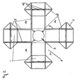
Fig. 2 zeigt in der Draufsicht eine flächenhafte Schwerkraftgründung (4) in Form eines Betonkreuzes mit Lasteinleitungsbereichen (2) und Leerrohren (3, 12). -
Fig. 3a zeigt ein Detail des Gründungskörpers mit einem Lasteinleitungsbereich (2). Zwischen Lasteinleitungsbereich (2) und Meeresboden (5) befindet sich ein zunächst mit Verpressmaterial unbeaufschlagtes Kissen (1), die Hohllage des Gründungskörpers (2) ist schematisch dargestellt. InFig. 3b ist das Kissen (1) mit Verpressmaterial gefüllt, der Kraftschluss zwischen Meeresboden (5) und Gründungskörper (2) ist hergestellt. Entlang der Lasteinleitungsbereiche (2) verlaufen Stahlschürzen (9), die in den Meeresgrund (5) einbinden. Durch den Betonkörper der Gründung und der Lasteinleitungsbereiche (2) führen Leerrohre (12) für Kompensationsinjektionen. -
Fig. 4 zeigt das Messsystem (10) im Mast (7) oberhalb der Wasseroberfläche.
-
Fig. 1 shows the establishment of a wind turbine in cross-section with inventive areal gravity foundation (4) by a concrete cross, which - in a preferred embodiment - rigid with the mast base / mast (7, 8) is connected. The concrete cross sits with support feet (2) on the seabed (5). In the Sohlfuge between load introduction area (2) and seabed (5) is located at the time of setting unencumbered surface Kis-sen (1) made of high-strength textile material, which is preferably impermeable to water. Through the concrete cross of the foundation run empty pipes for the pressing device and conduits (12) for later compensation injections. -
Fig. 2 shows in plan view a two-dimensional gravity foundation (4) in the form of a concrete cross with load introduction areas (2) and conduits (3, 12). -
Fig. 3a shows a detail of the foundation body with a load introduction area (2). Between the load introduction area (2) and the seabed (5) there is a cushion (1), first unloaded with grouting material, the hollow layer of the foundation body (2) is shown schematically. InFig. 3b is the cushion (1) filled with grout, the adhesion between the seabed (5) and foundation body (2) is made. Along the load introduction areas (2) run steel aprons (9), which embed in the seabed (5). Through the concrete body of the foundation and the load introduction areas (2) lead empty tubes (12) for compensation injections. -
Fig. 4 shows the measuring system (10) in the mast (7) above the water surface.
- 11
- verpressbares Kissencompressible cushion
- 22
- Stützfuß / LasteinleitungsbereichSupport leg / load introduction area
- 33
- Verpressleitung mit VentilenPressing line with valves
- 44
- Flächenhafte SchwerkraftgründungLarge-scale gravity foundation
- 55
- MeeresbodenSeabed
- 66
- Betonbalken, einzeln oder auch Teil eines GesamtkreuzesConcrete beams, single or part of a total cross
- 77
- Unterbau/MastuntersatzBase / pole subset
- 88th
- Mast der WindenergieanlageMast of the wind turbine
- 99
- Stahlschürzesteel apron
- 1010
- SchlauchwaagensystemLiquid Leveling System
- 1111
- Leerstelle in der flächenmäßigen GründungBlank space in the area-based foundation
- 1212
- Leerrohrconduit
Claims (9)
- Flat gravity foundation (4) for an offshore wind energy plant which transmits tilting moments of the mast (7, 8) as surface pressure to the sea bed (5), wherein the load introduction into the sea bed takes place in defined regions (2), characterized in that multi-chamber compressible cushions (1) are arranged under the load introduction regions (2) situated at the outer ends of the foundation, which cushions can be supplied at any time and multiply with material under pressure and thus allow a subsequent improvement of the non-positive engagement and a subsequent compensation of misalignments - even during the use duration.
- Flat gravity foundation (4) according to Claim 1, characterized in that the cushions (1) consist of a water-permeable, high-tensile-strength, geotextile material.
- Flat gravity foundation (4) according to at least one of Claims 1 and 2, characterized in that the flat gravity foundation (4) is designed as a prefabricated concrete cross or a concrete cross composed of individual concrete beams (6) and is provided with corresponding cushions (1) and all associated compression lines (3) and valves.
- Flat gravity foundation (4) according to Claim 3, characterized in that the compression lines (3) extend in the concrete of the beam element and of the mast (7, 8).
- Flat gravity foundation (4) according to at least one of Claims 3 and 4, characterized in that the compression lines (3) are guided beyond the water surface and from there are supplied in the dry state.
- Flat gravity foundation (4) according to at least one of Claims 3 to 5, characterized in that, in addition to the compression lines (3), the foundation element has suction lines leading to the load introduction regions (2).
- Flat gravity foundation (4) according to Claim 6, characterized in that compression lines (3) and suction lines are at least partially identical.
- Flat gravity foundation (4) according to at least one of Claims 1 to 7, characterized in that the flat gravity foundation (4) is equipped with an inclination measuring system at least during the compression of the cushions (1).
- Flat gravity foundation (4) according to Claim 8, characterized in that the inclination measuring system is an inclinometer measuring system.
Applications Claiming Priority (1)
| Application Number | Priority Date | Filing Date | Title |
|---|---|---|---|
| DE102009055175A DE102009055175B4 (en) | 2009-12-22 | 2009-12-22 | Readjustable surface foundation, preferably dissolved, for offshore wind turbines |
Publications (3)
| Publication Number | Publication Date |
|---|---|
| EP2362090A2 EP2362090A2 (en) | 2011-08-31 |
| EP2362090A3 EP2362090A3 (en) | 2011-10-05 |
| EP2362090B1 true EP2362090B1 (en) | 2014-01-08 |
Family
ID=44175969
Family Applications (1)
| Application Number | Title | Priority Date | Filing Date |
|---|---|---|---|
| EP10401197.8A Not-in-force EP2362090B1 (en) | 2009-12-22 | 2010-11-16 | Adjustable spread foundation, preferably separated, for offshore wind farms |
Country Status (3)
| Country | Link |
|---|---|
| EP (1) | EP2362090B1 (en) |
| DE (1) | DE102009055175B4 (en) |
| DK (1) | DK2362090T3 (en) |
Families Citing this family (5)
| Publication number | Priority date | Publication date | Assignee | Title |
|---|---|---|---|---|
| DE102010002181B3 (en) | 2010-02-22 | 2011-06-09 | Ed. Züblin Ag | Onshore-production plant for manufacturing offshore wind energy plant in e.g. port, has heavy load-module transporters provided on running tracks for transporting between intermediate storage facilities if necessary |
| DE102013002472A1 (en) | 2013-02-13 | 2014-08-14 | Strabag Offshore Wind Gmbh | "Gravity foundation for an offshore structure" |
| DE102015107252A1 (en) | 2015-05-08 | 2016-11-10 | Geomar Helmholtz-Zentrum Für Ozeanforschung Kiel - Stiftung Des Öffentlichen Rechts | Mechanical deep-sea sediment, marine raw material reservoir and / or undersea stabilization process and / or regulation / conditioning process of hydraulic properties of deep-sea sediments |
| CN108035376B (en) * | 2018-01-15 | 2023-07-04 | 河南理工大学 | Anti-deformation rectification foundation applicable to goaf site wind turbine generator and construction method thereof |
| CN110158638A (en) * | 2019-06-12 | 2019-08-23 | 长江勘测规划设计研究有限责任公司 | Offshore wind farm composite tube foundation construction structure and construction method |
Family Cites Families (5)
| Publication number | Priority date | Publication date | Assignee | Title |
|---|---|---|---|---|
| FR2054885A5 (en) * | 1969-07-30 | 1971-05-07 | Travaux Cie Indle | |
| FR2225030A5 (en) * | 1973-04-04 | 1974-10-31 | Kleber Colombes | Sea drilling rig positioning assembly - has platform at base of columns positioned on feet resting on seabed |
| FR2486562A1 (en) * | 1980-07-09 | 1982-01-15 | Coyne Bellier Bureau Ingenieur | FOUNDATION DEVICE FOR STRUCTURE, SUCH AS A PLATFORM, INCLUDING SELF-LIFTING, BASED ON A SUB-MARINE BASE, AND PLATFORMS OF THIS TYPE |
| DE102005006988A1 (en) | 2005-02-15 | 2006-08-17 | Ed. Züblin Ag | Surface foundation, preferably dissolved, for offshore wind turbines |
| GB0809521D0 (en) * | 2008-05-24 | 2008-07-02 | Marine Current Turbines Ltd | Installation of structures in water |
-
2009
- 2009-12-22 DE DE102009055175A patent/DE102009055175B4/en not_active Expired - Fee Related
-
2010
- 2010-11-16 DK DK10401197.8T patent/DK2362090T3/en active
- 2010-11-16 EP EP10401197.8A patent/EP2362090B1/en not_active Not-in-force
Also Published As
| Publication number | Publication date |
|---|---|
| DE102009055175A1 (en) | 2011-06-30 |
| EP2362090A3 (en) | 2011-10-05 |
| DK2362090T3 (en) | 2014-04-14 |
| DE102009055175B4 (en) | 2011-11-10 |
| EP2362090A2 (en) | 2011-08-31 |
Similar Documents
| Publication | Publication Date | Title |
|---|---|---|
| CN111535303B (en) | Manual hole digging pile and construction method thereof | |
| EP2362090B1 (en) | Adjustable spread foundation, preferably separated, for offshore wind farms | |
| EP2500473B1 (en) | Method of creating a foundation for a offshore structure | |
| DE2359540A1 (en) | UNDERWATER FUNDABLE EQUIPMENT AND PROCEDURE FOR ESTABLISHING IT ON THE SEA FLOOR | |
| CN105155602B (en) | A kind of many fulcrums foundation stabilization synthesis inclination correction method | |
| CN105525627A (en) | Two-way anchorage plate retaining wall and construction method thereof | |
| EP2698476B1 (en) | Method for the construction of an offshore structure and foundation for an offshore structure | |
| CN108661069A (en) | Close on the wall piled anchor composite structure and method of old Retaining Wall Reinforcement under the load of river road surface | |
| CN104790412B (en) | Big width foundation pit supporting construction in the case of artesian water | |
| EP2700750B1 (en) | Foundation pile for offshore structures and method for constructing a foundation pile for offshore structures | |
| CN107700474A (en) | A kind of existing construction foundation reinforcement means and campshed formula diaphram wall | |
| CN104389315A (en) | Consolidation grouting drilled pile wall and construction method thereof | |
| DE102010032259B4 (en) | Method for installing a gravity foundation for an offshore installation | |
| DE102017115817A1 (en) | Foundation for an offshore wind energy plant | |
| DE10239278B4 (en) | Foundation for hydraulic structures | |
| EP2955277B1 (en) | Foundation structure for offshore assemblies, in particular wind turbines | |
| CN111622234A (en) | Unloading type thin-wall box-type retaining wall supported by obliquely and vertically combined steel pipe pile and construction process | |
| CN207419441U (en) | A kind of campshed formula diaphram wall | |
| WO2011092038A1 (en) | Method and installation assembly having a flat foundation | |
| DE102011012450A1 (en) | Method for installing heavyweight foundation system for offshore-wind energy plant, involves prestressing heavyweight foundation in laterally limited manner by ballast bodies before tower and/or housing of tower is mounted | |
| CN104452798A (en) | Offshore wind turbine foundation structure and equipment and construction method of offshore wind turbine foundation equipment | |
| CN209066483U (en) | A kind of assembled ecology retaining wall | |
| CN109371954A (en) | A kind of construction method of PHC tubular pole consolidation draining system in soft soil foundation | |
| CN204626419U (en) | Large width foundation pit supporting construction | |
| DE102012025120A1 (en) | Method of constructing an offshore structure |
Legal Events
| Date | Code | Title | Description |
|---|---|---|---|
| PUAI | Public reference made under article 153(3) epc to a published international application that has entered the european phase |
Free format text: ORIGINAL CODE: 0009012 |
|
| AK | Designated contracting states |
Kind code of ref document: A2 Designated state(s): AL AT BE BG CH CY CZ DE DK EE ES FI FR GB GR HR HU IE IS IT LI LT LU LV MC MK MT NL NO PL PT RO RS SE SI SK SM TR |
|
| AX | Request for extension of the european patent |
Extension state: BA ME |
|
| PUAL | Search report despatched |
Free format text: ORIGINAL CODE: 0009013 |
|
| AK | Designated contracting states |
Kind code of ref document: A3 Designated state(s): AL AT BE BG CH CY CZ DE DK EE ES FI FR GB GR HR HU IE IS IT LI LT LU LV MC MK MT NL NO PL PT RO RS SE SI SK SM TR |
|
| AX | Request for extension of the european patent |
Extension state: BA ME |
|
| RIC1 | Information provided on ipc code assigned before grant |
Ipc: F03D 1/00 20060101AFI20110901BHEP |
|
| RAP1 | Party data changed (applicant data changed or rights of an application transferred) |
Owner name: STRABAG OFFSHORE WIND GMBH |
|
| 17P | Request for examination filed |
Effective date: 20120328 |
|
| 17Q | First examination report despatched |
Effective date: 20120817 |
|
| REG | Reference to a national code |
Ref country code: DE Ref legal event code: R079 Ref document number: 502010005882 Country of ref document: DE Free format text: PREVIOUS MAIN CLASS: F03D0001000000 Ipc: F03D0011040000 |
|
| RIC1 | Information provided on ipc code assigned before grant |
Ipc: F03D 11/04 20060101AFI20130418BHEP |
|
| GRAP | Despatch of communication of intention to grant a patent |
Free format text: ORIGINAL CODE: EPIDOSNIGR1 |
|
| RAP1 | Party data changed (applicant data changed or rights of an application transferred) |
Owner name: STRABAG OFFSHORE WIND GMBH |
|
| INTG | Intention to grant announced |
Effective date: 20130722 |
|
| GRAS | Grant fee paid |
Free format text: ORIGINAL CODE: EPIDOSNIGR3 |
|
| GRAA | (expected) grant |
Free format text: ORIGINAL CODE: 0009210 |
|
| AK | Designated contracting states |
Kind code of ref document: B1 Designated state(s): AL AT BE BG CH CY CZ DE DK EE ES FI FR GB GR HR HU IE IS IT LI LT LU LV MC MK MT NL NO PL PT RO RS SE SI SK SM TR |
|
| REG | Reference to a national code |
Ref country code: GB Ref legal event code: FG4D Free format text: NOT ENGLISH |
|
| REG | Reference to a national code |
Ref country code: CH Ref legal event code: EP |
|
| REG | Reference to a national code |
Ref country code: IE Ref legal event code: FG4D Free format text: LANGUAGE OF EP DOCUMENT: GERMAN |
|
| REG | Reference to a national code |
Ref country code: AT Ref legal event code: REF Ref document number: 648919 Country of ref document: AT Kind code of ref document: T Effective date: 20140215 |
|
| REG | Reference to a national code |
Ref country code: DE Ref legal event code: R096 Ref document number: 502010005882 Country of ref document: DE Effective date: 20140220 |
|
| REG | Reference to a national code |
Ref country code: DK Ref legal event code: T3 Effective date: 20140409 |
|
| REG | Reference to a national code |
Ref country code: NL Ref legal event code: T3 |
|
| REG | Reference to a national code |
Ref country code: LT Ref legal event code: MG4D |
|
| PG25 | Lapsed in a contracting state [announced via postgrant information from national office to epo] |
Ref country code: IS Free format text: LAPSE BECAUSE OF FAILURE TO SUBMIT A TRANSLATION OF THE DESCRIPTION OR TO PAY THE FEE WITHIN THE PRESCRIBED TIME-LIMIT Effective date: 20140508 Ref country code: LT Free format text: LAPSE BECAUSE OF FAILURE TO SUBMIT A TRANSLATION OF THE DESCRIPTION OR TO PAY THE FEE WITHIN THE PRESCRIBED TIME-LIMIT Effective date: 20140108 Ref country code: NO Free format text: LAPSE BECAUSE OF FAILURE TO SUBMIT A TRANSLATION OF THE DESCRIPTION OR TO PAY THE FEE WITHIN THE PRESCRIBED TIME-LIMIT Effective date: 20140408 |
|
| PG25 | Lapsed in a contracting state [announced via postgrant information from national office to epo] |
Ref country code: PT Free format text: LAPSE BECAUSE OF FAILURE TO SUBMIT A TRANSLATION OF THE DESCRIPTION OR TO PAY THE FEE WITHIN THE PRESCRIBED TIME-LIMIT Effective date: 20140508 Ref country code: SE Free format text: LAPSE BECAUSE OF FAILURE TO SUBMIT A TRANSLATION OF THE DESCRIPTION OR TO PAY THE FEE WITHIN THE PRESCRIBED TIME-LIMIT Effective date: 20140108 Ref country code: CY Free format text: LAPSE BECAUSE OF FAILURE TO SUBMIT A TRANSLATION OF THE DESCRIPTION OR TO PAY THE FEE WITHIN THE PRESCRIBED TIME-LIMIT Effective date: 20140108 Ref country code: FI Free format text: LAPSE BECAUSE OF FAILURE TO SUBMIT A TRANSLATION OF THE DESCRIPTION OR TO PAY THE FEE WITHIN THE PRESCRIBED TIME-LIMIT Effective date: 20140108 Ref country code: ES Free format text: LAPSE BECAUSE OF FAILURE TO SUBMIT A TRANSLATION OF THE DESCRIPTION OR TO PAY THE FEE WITHIN THE PRESCRIBED TIME-LIMIT Effective date: 20140108 |
|
| PG25 | Lapsed in a contracting state [announced via postgrant information from national office to epo] |
Ref country code: HR Free format text: LAPSE BECAUSE OF FAILURE TO SUBMIT A TRANSLATION OF THE DESCRIPTION OR TO PAY THE FEE WITHIN THE PRESCRIBED TIME-LIMIT Effective date: 20140108 Ref country code: LV Free format text: LAPSE BECAUSE OF FAILURE TO SUBMIT A TRANSLATION OF THE DESCRIPTION OR TO PAY THE FEE WITHIN THE PRESCRIBED TIME-LIMIT Effective date: 20140108 Ref country code: RS Free format text: LAPSE BECAUSE OF FAILURE TO SUBMIT A TRANSLATION OF THE DESCRIPTION OR TO PAY THE FEE WITHIN THE PRESCRIBED TIME-LIMIT Effective date: 20140108 |
|
| REG | Reference to a national code |
Ref country code: DE Ref legal event code: R097 Ref document number: 502010005882 Country of ref document: DE |
|
| PG25 | Lapsed in a contracting state [announced via postgrant information from national office to epo] |
Ref country code: EE Free format text: LAPSE BECAUSE OF FAILURE TO SUBMIT A TRANSLATION OF THE DESCRIPTION OR TO PAY THE FEE WITHIN THE PRESCRIBED TIME-LIMIT Effective date: 20140108 Ref country code: RO Free format text: LAPSE BECAUSE OF FAILURE TO SUBMIT A TRANSLATION OF THE DESCRIPTION OR TO PAY THE FEE WITHIN THE PRESCRIBED TIME-LIMIT Effective date: 20140108 Ref country code: CZ Free format text: LAPSE BECAUSE OF FAILURE TO SUBMIT A TRANSLATION OF THE DESCRIPTION OR TO PAY THE FEE WITHIN THE PRESCRIBED TIME-LIMIT Effective date: 20140108 |
|
| PLBE | No opposition filed within time limit |
Free format text: ORIGINAL CODE: 0009261 |
|
| STAA | Information on the status of an ep patent application or granted ep patent |
Free format text: STATUS: NO OPPOSITION FILED WITHIN TIME LIMIT |
|
| PG25 | Lapsed in a contracting state [announced via postgrant information from national office to epo] |
Ref country code: PL Free format text: LAPSE BECAUSE OF FAILURE TO SUBMIT A TRANSLATION OF THE DESCRIPTION OR TO PAY THE FEE WITHIN THE PRESCRIBED TIME-LIMIT Effective date: 20140108 Ref country code: SK Free format text: LAPSE BECAUSE OF FAILURE TO SUBMIT A TRANSLATION OF THE DESCRIPTION OR TO PAY THE FEE WITHIN THE PRESCRIBED TIME-LIMIT Effective date: 20140108 |
|
| 26N | No opposition filed |
Effective date: 20141009 |
|
| REG | Reference to a national code |
Ref country code: DE Ref legal event code: R097 Ref document number: 502010005882 Country of ref document: DE Effective date: 20141009 |
|
| PG25 | Lapsed in a contracting state [announced via postgrant information from national office to epo] |
Ref country code: SI Free format text: LAPSE BECAUSE OF FAILURE TO SUBMIT A TRANSLATION OF THE DESCRIPTION OR TO PAY THE FEE WITHIN THE PRESCRIBED TIME-LIMIT Effective date: 20140108 |
|
| REG | Reference to a national code |
Ref country code: DE Ref legal event code: R119 Ref document number: 502010005882 Country of ref document: DE |
|
| PG25 | Lapsed in a contracting state [announced via postgrant information from national office to epo] |
Ref country code: MC Free format text: LAPSE BECAUSE OF FAILURE TO SUBMIT A TRANSLATION OF THE DESCRIPTION OR TO PAY THE FEE WITHIN THE PRESCRIBED TIME-LIMIT Effective date: 20140108 Ref country code: BE Free format text: LAPSE BECAUSE OF NON-PAYMENT OF DUE FEES Effective date: 20141130 Ref country code: LU Free format text: LAPSE BECAUSE OF FAILURE TO SUBMIT A TRANSLATION OF THE DESCRIPTION OR TO PAY THE FEE WITHIN THE PRESCRIBED TIME-LIMIT Effective date: 20141116 |
|
| REG | Reference to a national code |
Ref country code: CH Ref legal event code: PL |
|
| PG25 | Lapsed in a contracting state [announced via postgrant information from national office to epo] |
Ref country code: CH Free format text: LAPSE BECAUSE OF NON-PAYMENT OF DUE FEES Effective date: 20141130 Ref country code: LI Free format text: LAPSE BECAUSE OF NON-PAYMENT OF DUE FEES Effective date: 20141130 |
|
| REG | Reference to a national code |
Ref country code: IE Ref legal event code: MM4A |
|
| PG25 | Lapsed in a contracting state [announced via postgrant information from national office to epo] |
Ref country code: DE Free format text: LAPSE BECAUSE OF NON-PAYMENT OF DUE FEES Effective date: 20150602 Ref country code: IE Free format text: LAPSE BECAUSE OF NON-PAYMENT OF DUE FEES Effective date: 20141116 |
|
| REG | Reference to a national code |
Ref country code: FR Ref legal event code: PLFP Year of fee payment: 6 |
|
| PG25 | Lapsed in a contracting state [announced via postgrant information from national office to epo] |
Ref country code: SM Free format text: LAPSE BECAUSE OF FAILURE TO SUBMIT A TRANSLATION OF THE DESCRIPTION OR TO PAY THE FEE WITHIN THE PRESCRIBED TIME-LIMIT Effective date: 20140108 |
|
| PG25 | Lapsed in a contracting state [announced via postgrant information from national office to epo] |
Ref country code: GR Free format text: LAPSE BECAUSE OF FAILURE TO SUBMIT A TRANSLATION OF THE DESCRIPTION OR TO PAY THE FEE WITHIN THE PRESCRIBED TIME-LIMIT Effective date: 20140409 Ref country code: IT Free format text: LAPSE BECAUSE OF FAILURE TO SUBMIT A TRANSLATION OF THE DESCRIPTION OR TO PAY THE FEE WITHIN THE PRESCRIBED TIME-LIMIT Effective date: 20140108 Ref country code: BG Free format text: LAPSE BECAUSE OF FAILURE TO SUBMIT A TRANSLATION OF THE DESCRIPTION OR TO PAY THE FEE WITHIN THE PRESCRIBED TIME-LIMIT Effective date: 20140108 |
|
| PG25 | Lapsed in a contracting state [announced via postgrant information from national office to epo] |
Ref country code: TR Free format text: LAPSE BECAUSE OF FAILURE TO SUBMIT A TRANSLATION OF THE DESCRIPTION OR TO PAY THE FEE WITHIN THE PRESCRIBED TIME-LIMIT Effective date: 20140108 Ref country code: HU Free format text: LAPSE BECAUSE OF FAILURE TO SUBMIT A TRANSLATION OF THE DESCRIPTION OR TO PAY THE FEE WITHIN THE PRESCRIBED TIME-LIMIT; INVALID AB INITIO Effective date: 20101116 Ref country code: MT Free format text: LAPSE BECAUSE OF FAILURE TO SUBMIT A TRANSLATION OF THE DESCRIPTION OR TO PAY THE FEE WITHIN THE PRESCRIBED TIME-LIMIT Effective date: 20140108 |
|
| REG | Reference to a national code |
Ref country code: FR Ref legal event code: PLFP Year of fee payment: 7 |
|
| REG | Reference to a national code |
Ref country code: AT Ref legal event code: MM01 Ref document number: 648919 Country of ref document: AT Kind code of ref document: T Effective date: 20151116 |
|
| PGFP | Annual fee paid to national office [announced via postgrant information from national office to epo] |
Ref country code: FR Payment date: 20161124 Year of fee payment: 7 Ref country code: DK Payment date: 20161124 Year of fee payment: 7 Ref country code: NL Payment date: 20161124 Year of fee payment: 7 Ref country code: GB Payment date: 20161124 Year of fee payment: 7 |
|
| PG25 | Lapsed in a contracting state [announced via postgrant information from national office to epo] |
Ref country code: AT Free format text: LAPSE BECAUSE OF NON-PAYMENT OF DUE FEES Effective date: 20151116 |
|
| REG | Reference to a national code |
Ref country code: DK Ref legal event code: EBP Effective date: 20171130 |
|
| PG25 | Lapsed in a contracting state [announced via postgrant information from national office to epo] |
Ref country code: MK Free format text: LAPSE BECAUSE OF FAILURE TO SUBMIT A TRANSLATION OF THE DESCRIPTION OR TO PAY THE FEE WITHIN THE PRESCRIBED TIME-LIMIT Effective date: 20140108 |
|
| REG | Reference to a national code |
Ref country code: NL Ref legal event code: MM Effective date: 20171201 |
|
| GBPC | Gb: european patent ceased through non-payment of renewal fee |
Effective date: 20171116 |
|
| REG | Reference to a national code |
Ref country code: FR Ref legal event code: ST Effective date: 20180731 |
|
| PG25 | Lapsed in a contracting state [announced via postgrant information from national office to epo] |
Ref country code: AL Free format text: LAPSE BECAUSE OF FAILURE TO SUBMIT A TRANSLATION OF THE DESCRIPTION OR TO PAY THE FEE WITHIN THE PRESCRIBED TIME-LIMIT Effective date: 20140108 Ref country code: NL Free format text: LAPSE BECAUSE OF NON-PAYMENT OF DUE FEES Effective date: 20171201 Ref country code: FR Free format text: LAPSE BECAUSE OF NON-PAYMENT OF DUE FEES Effective date: 20171130 |
|
| PG25 | Lapsed in a contracting state [announced via postgrant information from national office to epo] |
Ref country code: GB Free format text: LAPSE BECAUSE OF NON-PAYMENT OF DUE FEES Effective date: 20171116 Ref country code: DK Free format text: LAPSE BECAUSE OF NON-PAYMENT OF DUE FEES Effective date: 20171130 |