EP2362082B1 - Engine system control device - Google Patents
Engine system control device Download PDFInfo
- Publication number
- EP2362082B1 EP2362082B1 EP20080878587 EP08878587A EP2362082B1 EP 2362082 B1 EP2362082 B1 EP 2362082B1 EP 20080878587 EP20080878587 EP 20080878587 EP 08878587 A EP08878587 A EP 08878587A EP 2362082 B1 EP2362082 B1 EP 2362082B1
- Authority
- EP
- European Patent Office
- Prior art keywords
- compression ratio
- intake
- air
- sensor
- exhaust
- Prior art date
- Legal status (The legal status is an assumption and is not a legal conclusion. Google has not performed a legal analysis and makes no representation as to the accuracy of the status listed.)
- Not-in-force
Links
Images


Classifications
-
- F—MECHANICAL ENGINEERING; LIGHTING; HEATING; WEAPONS; BLASTING
- F02—COMBUSTION ENGINES; HOT-GAS OR COMBUSTION-PRODUCT ENGINE PLANTS
- F02D—CONTROLLING COMBUSTION ENGINES
- F02D41/00—Electrical control of supply of combustible mixture or its constituents
- F02D41/22—Safety or indicating devices for abnormal conditions
- F02D41/221—Safety or indicating devices for abnormal conditions relating to the failure of actuators or electrically driven elements
-
- F—MECHANICAL ENGINEERING; LIGHTING; HEATING; WEAPONS; BLASTING
- F02—COMBUSTION ENGINES; HOT-GAS OR COMBUSTION-PRODUCT ENGINE PLANTS
- F02D—CONTROLLING COMBUSTION ENGINES
- F02D15/00—Varying compression ratio
-
- F—MECHANICAL ENGINEERING; LIGHTING; HEATING; WEAPONS; BLASTING
- F02—COMBUSTION ENGINES; HOT-GAS OR COMBUSTION-PRODUCT ENGINE PLANTS
- F02D—CONTROLLING COMBUSTION ENGINES
- F02D15/00—Varying compression ratio
- F02D15/04—Varying compression ratio by alteration of volume of compression space without changing piston stroke
-
- F—MECHANICAL ENGINEERING; LIGHTING; HEATING; WEAPONS; BLASTING
- F02—COMBUSTION ENGINES; HOT-GAS OR COMBUSTION-PRODUCT ENGINE PLANTS
- F02D—CONTROLLING COMBUSTION ENGINES
- F02D41/00—Electrical control of supply of combustible mixture or its constituents
- F02D41/02—Circuit arrangements for generating control signals
- F02D41/021—Introducing corrections for particular conditions exterior to the engine
- F02D41/0235—Introducing corrections for particular conditions exterior to the engine in relation with the state of the exhaust gas treating apparatus
-
- F—MECHANICAL ENGINEERING; LIGHTING; HEATING; WEAPONS; BLASTING
- F02—COMBUSTION ENGINES; HOT-GAS OR COMBUSTION-PRODUCT ENGINE PLANTS
- F02D—CONTROLLING COMBUSTION ENGINES
- F02D41/00—Electrical control of supply of combustible mixture or its constituents
- F02D41/02—Circuit arrangements for generating control signals
- F02D41/14—Introducing closed-loop corrections
- F02D41/1438—Introducing closed-loop corrections using means for determining characteristics of the combustion gases; Sensors therefor
- F02D41/1486—Introducing closed-loop corrections using means for determining characteristics of the combustion gases; Sensors therefor with correction for particular operating conditions
- F02D41/1488—Inhibiting the regulation
-
- F—MECHANICAL ENGINEERING; LIGHTING; HEATING; WEAPONS; BLASTING
- F02—COMBUSTION ENGINES; HOT-GAS OR COMBUSTION-PRODUCT ENGINE PLANTS
- F02D—CONTROLLING COMBUSTION ENGINES
- F02D41/00—Electrical control of supply of combustible mixture or its constituents
- F02D41/02—Circuit arrangements for generating control signals
- F02D41/14—Introducing closed-loop corrections
- F02D41/1438—Introducing closed-loop corrections using means for determining characteristics of the combustion gases; Sensors therefor
- F02D41/1493—Details
- F02D41/1495—Detection of abnormalities in the air/fuel ratio feedback system
-
- F—MECHANICAL ENGINEERING; LIGHTING; HEATING; WEAPONS; BLASTING
- F01—MACHINES OR ENGINES IN GENERAL; ENGINE PLANTS IN GENERAL; STEAM ENGINES
- F01N—GAS-FLOW SILENCERS OR EXHAUST APPARATUS FOR MACHINES OR ENGINES IN GENERAL; GAS-FLOW SILENCERS OR EXHAUST APPARATUS FOR INTERNAL COMBUSTION ENGINES
- F01N11/00—Monitoring or diagnostic devices for exhaust-gas treatment apparatus, e.g. for catalytic activity
-
- F—MECHANICAL ENGINEERING; LIGHTING; HEATING; WEAPONS; BLASTING
- F01—MACHINES OR ENGINES IN GENERAL; ENGINE PLANTS IN GENERAL; STEAM ENGINES
- F01N—GAS-FLOW SILENCERS OR EXHAUST APPARATUS FOR MACHINES OR ENGINES IN GENERAL; GAS-FLOW SILENCERS OR EXHAUST APPARATUS FOR INTERNAL COMBUSTION ENGINES
- F01N2550/00—Monitoring or diagnosing the deterioration of exhaust systems
-
- F—MECHANICAL ENGINEERING; LIGHTING; HEATING; WEAPONS; BLASTING
- F02—COMBUSTION ENGINES; HOT-GAS OR COMBUSTION-PRODUCT ENGINE PLANTS
- F02D—CONTROLLING COMBUSTION ENGINES
- F02D41/00—Electrical control of supply of combustible mixture or its constituents
- F02D41/22—Safety or indicating devices for abnormal conditions
- F02D2041/227—Limping Home, i.e. taking specific engine control measures at abnormal conditions
-
- F—MECHANICAL ENGINEERING; LIGHTING; HEATING; WEAPONS; BLASTING
- F02—COMBUSTION ENGINES; HOT-GAS OR COMBUSTION-PRODUCT ENGINE PLANTS
- F02D—CONTROLLING COMBUSTION ENGINES
- F02D41/00—Electrical control of supply of combustible mixture or its constituents
- F02D41/02—Circuit arrangements for generating control signals
- F02D41/14—Introducing closed-loop corrections
- F02D41/1438—Introducing closed-loop corrections using means for determining characteristics of the combustion gases; Sensors therefor
- F02D41/1444—Introducing closed-loop corrections using means for determining characteristics of the combustion gases; Sensors therefor characterised by the characteristics of the combustion gases
- F02D41/1446—Introducing closed-loop corrections using means for determining characteristics of the combustion gases; Sensors therefor characterised by the characteristics of the combustion gases the characteristics being exhaust temperatures
-
- F—MECHANICAL ENGINEERING; LIGHTING; HEATING; WEAPONS; BLASTING
- F02—COMBUSTION ENGINES; HOT-GAS OR COMBUSTION-PRODUCT ENGINE PLANTS
- F02D—CONTROLLING COMBUSTION ENGINES
- F02D41/00—Electrical control of supply of combustible mixture or its constituents
- F02D41/22—Safety or indicating devices for abnormal conditions
- F02D41/222—Safety or indicating devices for abnormal conditions relating to the failure of sensors or parameter detection devices
-
- Y—GENERAL TAGGING OF NEW TECHNOLOGICAL DEVELOPMENTS; GENERAL TAGGING OF CROSS-SECTIONAL TECHNOLOGIES SPANNING OVER SEVERAL SECTIONS OF THE IPC; TECHNICAL SUBJECTS COVERED BY FORMER USPC CROSS-REFERENCE ART COLLECTIONS [XRACs] AND DIGESTS
- Y02—TECHNOLOGIES OR APPLICATIONS FOR MITIGATION OR ADAPTATION AGAINST CLIMATE CHANGE
- Y02T—CLIMATE CHANGE MITIGATION TECHNOLOGIES RELATED TO TRANSPORTATION
- Y02T10/00—Road transport of goods or passengers
- Y02T10/10—Internal combustion engine [ICE] based vehicles
- Y02T10/40—Engine management systems
Definitions
- the present invention relates to an engine system control device to be applied to an engine system (system provided with an engine such as an automobile).
- the present invention particularly relates to an engine system control device in the case where the engine has a variable compression ratio mechanism capable of changing a compression ratio.
- state determination of an intake and exhaust system that is, failure diagnosis is performed by an engine electronic control unit (hereinafter, called as the "ECU").
- ECU engine electronic control unit
- OBD on-board diagnosis of the intake and exhaust system includes catalyst failure diagnosis, exhaust gas sensor failure diagnosis, and canister purge system failure diagnosis.
- a catalyst for purifying an exhaust gas is placed in an exhaust passage for this type of system.
- This catalyst is deteriorated due to harmful components (such as lead and sulfur) in fuel and excessive heating.
- harmful components such as lead and sulfur
- an exhaust gas purifying ratio is degraded, and exhaust emission is increased.
- various devices for determining deterioration of the catalyst are conventionally proposed (such as Japanese Patent Application Publication No. 1993(H5)-133264 and 2004-28029).
- This kind of catalyst a so-called ternary catalyst is widely used.
- This ternary catalyst has a function called an oxygen absorption function or an oxygen storage function.
- an air-fuel ratio of the fuel-mixing air is lean
- such a function is to reduce NOx (nitrogen oxide) in the exhaust gas and absorb (store) oxygen taken from NOx inside.
- the function is to release the absorbed oxygen for oxidation of unburned components such as HC and CO in the exhaust gas.
- oxygen absorption amount the maximum value of an oxygen amount to be absorbed by the ternary catalyst
- a first air-fuel ratio sensor is arranged at a position on the upstream side of a ternary catalyst in an exhaust passage and a second air-fuel ratio sensor is arranged at a position on the downstream side of the ternary catalyst in the exhaust passage.
- Deterioration determination of the ternary catalyst (calculation of the maximum oxygen absorption amount) with such a configuration is performed as follows. Firstly, the air-fuel ratio of the fuel-mixing air supplied into a cylinder of an engine is set to be a predetermined lean air-fuel ratio for a predetermined time. Thereby, oxygen is absorbed by the ternary catalyst up to a limit of an absorbing ability. After that, the air-fuel ratio of the fuel-mixing air is forcibly changed to a predetermined rich air-fuel ratio. Then, the air-fuel ratio detected by the second air-fuel ratio sensor is changed to the rich ratio after maintained to be a theoretical air-fuel ratio only for a fixed time ⁇ t. The maximum oxygen absorption amount is determined based on a difference ⁇ (A/F) between the theoretical air-fuel ratio and the rich air-fuel ratio, the time ⁇ t, and an intake air amount of this time.
- ⁇ A/F
- This maximum oxygen absorption amount is changed even with a temperature of the ternary catalyst. Specifically, when the temperature of the ternary catalyst is increased, the maximum oxygen absorption amount is increased. Thus, when the deterioration determination of the catalyst is performed based on the maximum oxygen absorption amount calculated without considering the temperature of the catalyst, there is a problem that determination precision is not favorable. In a catalyst deterioration degree detection device disclosed in Japanese Patent Application Publication No. 2004-28029 , the maximum oxygen absorption amount is corrected based on the temperature of the catalyst in a calculation period of the maximum oxygen absorption amount.
- air-fuel ratio feedback control In order to control the air-fuel ratio of the engine, so-called air-fuel ratio feedback control is generally performed. This control is performed based on an output of an exhaust gas sensor (air-fuel ratio sensor) placed in an exhaust passage.
- this exhaust gas sensor is an oxygen sensor for generating an output in accordance with oxygen concentration in the exhaust gas.
- This exhaust gas sensor is provided on the upstream side and/or the downstream side in the flowing direction of the exhaust gas relative to the catalyst for purifying the exhaust gas.
- a solid electrolyte type oxygen sensor having an output characteristic in which an output is substantially fixed on the rich and lean sides of the theoretical air-fuel ratio whereas the output is radically changed around the theoretical air-fuel ratio is used.
- the solid electrolyte type oxygen sensor or a limiting current type oxygen concentration sensor having a relatively linear output characteristic within a wide air-fuel ratio range is used.
- the exhaust gas sensor is also used to calculate the maximum oxygen absorption amount for the deterioration determination of the catalyst as described above. Therefore, when the failure such as the deterioration is generated in the exhaust gas sensor, the deterioration determination of the catalyst cannot be accurately performed.
- a device for diagnosing the failure of this exhaust gas sensor is conventionally proposed (for example, refer to Japanese Patent Application Publication No. 2003-254135 , 2004-225684 , 2007-16712 , and the like).
- This device is to determine whether or not the exhaust gas sensor normally works in accordance with a responding state of the exhaust gas sensor to an air-fuel ratio change of the fuel-mixing air.
- the air-fuel ratio is alternately forcibly changed between a predetermined rich air-fuel ratio and a predetermined lean air-fuel ratio, and presence of failure of a sensor is determined based on whether or not a sensor output rightly following this air-fuel ratio change is generated.
- JP H06 159153 A discloses an abnormality diagnostic means in an exhaust recirculation system which operation is inhibited when abnormality is detected especially in operational condition detecting means of an engine. It is thus discriminated by an electronic control unit whether abnormality is present at an output signal value from the valve opening sensor of an exhaust reflux rate control valve. At the same time, an operational condition in the engine 1 is discriminated based on detected signals from various kinds of sensors, and the target valve opening value of the EGR valve 16 according to the discriminated result is calculated and set.
- These main sensors are a throttle valve opening sensor 4, an intake pipe inner absolute pressure sensor 7, an engine cooling water temperature sensor 8, an engine rotational speed sensor 9, a catalytic temperature sensor 30 and the like. The EGR control is not appropriately performed if only one of these sensors is abnormal.
- EP 1 464 814 A2 discloses an internal combustion engine having a compression ratio varying mechanism in which, in response to detection of the occurrence of any failure or trouble in the compression ratio varying mechanism, the control technique of the invention restricts execution of a specific control, which has adverse effects on stable combustion of the air-fuel mixture.
- the specific control having adverse effects on the stable combustion of the air-fuel mixture includes warm-up ignition delay control, lean barn control, and EGR control. This arrangement, ensures table combustion of the air-fuel mixture, even when the compression ratio varying mechanism is locked in at a low compression ratio.
- the technique of the invention thus enables the internal combustion engine to be driven stably, even in the case of the occurrence of any failure or trouble in the compression ratio varying mechanism.
- variable compression ratio capable of changing a compression ratio
- the variable "compression ratio” here includes a "mechanical compression ratio” and an "actual compression ratio”.
- the mechanical compression ratio is a value determined by dividing the sum of clearance volume (combustion chamber volume at a piston top dead center) and volume of a piston stroke by the clearance volume, and is also called as a nominal compression ratio or a geometrical compression ratio.
- the mechanical compression ratio can be changed for example by relatively moving a crankcase on which a crankshaft is rotatably supported, and a cylinder block with an upper end thereof to which a cylinder head is fixed along an axis of a cylinder.
- the mechanical compression ratio can be changed by, in the case where a connecting rod (member for coupling a piston and the crankshaft) is bendable, changing a bent state of this connecting rod.
- the actual compression ratio is an effective compression ratio to the intake air, and typically a value determined by dividing the combustion chamber volume at the time of starting compression of the intake air by the combustion chamber volume at the time of finishing the compression.
- This actual compression ratio can be changed in accordance with the above change in the mechanical compression ratio.
- This actual compression ratio can be changed by varying action timing of an intake valve and an exhaust valve together with the change in the mechanical compression ratio or in place of this change.
- an expansion ratio can also be changed by the change in the mechanical compression ratio.
- the mechanical compression ratio, the actual compression ratio, and the expansion ratio can be independently set and changed (for example, refer to Japanese Patent Application Publication No. 2007-303423 , 2008-19799 , 2008-157128 , and the like).
- An object of the present invention is to improve precision of the on-board diagnosis of the intake and exhaust system in an engine system provided with an engine in which the compression ratio or the expansion ratio is variable. This object is achieved by an engine system control device according to claim 1. Further advantageous developments are subject-matters of the dependent claims.
- control device An engine system control device of the present invention (hereinafter, simply referred to as the "control device") is applied to an engine system provided with an engine having a variable compression ratio mechanism capable of changing a compression ratio.
- this engine includes an engine in which an expansion ratio is variable. That is, this engine may include an engine in which a mechanical compression ratio, an actual compression ratio, and the expansion ratio can be independently set and changed by changing the mechanical compression ratio and opening and closing timing of intake and exhaust valves.
- This control device is provided with a compression ratio acquiring unit, a compression ratio control system failure detecting unit, an intake and exhaust system determining unit, and an intake and exhaust system determination permitting unit.
- unit may be called as a term “means” (such as the “compression ratio acquiring means", or the like, the same is applied to the remaining similar items).
- the compression ratio acquiring unit is configured to acquire a setting state of the compression ratio by the variable compression ratio mechanism (the term "acquiring" includes detection and estimation, the same is applied to the remaining similar items).
- the compression ratio control system failure detecting unit is configured to detect generation of failure in a compression ratio control system including the variable compression ratio mechanism and the compression ratio acquiring unit.
- the intake and exhaust system determining unit is configured to determine a state of a member placed in an intake and exhaust system of the engine.
- this intake and exhaust system determining unit may be configured to determine the state of the member placed in a passage of an exhaust gas discharged from the engine (such as a catalyst or an exhaust gas sensor).
- the intake and exhaust system determination permitting unit is configured to permit determination by the intake and exhaust system determining unit.
- the intake and exhaust system determination permitting unit is configured to inhibit the determination by the intake and exhaust system determining unit, in the case where the compression ratio control system failure detecting unit detects the generation of the failure.
- the intake and exhaust system determination permitting unit is configured to permit the determination by the intake and exhaust system determining unit, in the case where the compression ratio control system failure detecting unit detects the generation of the failure but the setting state of the compression ratio is acquirable.
- the intake and exhaust system determination permitting unit may be configured to permit the determination by the intake and exhaust system determining unit in the case where the compression ratio control system failure detecting unit detects the generation of the failure but the temperature is acquirable by the temperature acquiring unit.
- the compression ratio control system in the case where the compression ratio control system normally works, and a predetermined determination condition is met, the determination of the state of the member (such as catalyst OBD or exhaust gas sensor OBD) is performed. Meanwhile, in the case where the failure is generated in the compression ratio control system and the setting state of the compression ratio or the expansion ratio becomes unknown, the determination of the state of the member is inhibited.
- the state of the member such as catalyst OBD or exhaust gas sensor OBD
- the determination of the state of the member is favorably performed. Therefore, in these occasions, the determination can be permitted.
- the on-board diagnosis of the intake and exhaust system (on-board diagnosis influenced by a state of the exhaust gas in particular) is properly performed in the engine system provided with the engine in which the compression ratio or the expansion ratio is variable. Therefore, precision of the diagnosis can be improved more than that of the conventional examples.
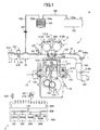
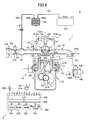
- Fig. 1 is a schematic configuration diagram of major parts of an engine system S (such as a vehicle) to which the present invention is applied.
- This engine system S is provided with an engine 1, and a control device 2 serving as one embodiment of the present invention.
- a side sectional view of the engine 1 by plane orthogonal to the cylinder arranging direction is shown in Fig. 1 .
- the engine 1 is formed so that a mechanical compression ratio is variable within a predetermined range.
- the engine 1 is formed so that the mechanical compression ratio, an actual compression ratio, and an expansion ratio can be substantially independently set and changed.
- the engine 1 is provided with a cylinder block 11, a cylinder head 12, a crankcase 13, and a variable compression ratio mechanism 14.
- An intake passage 15 and an exhaust passage 16 are connected to the engine 1.
- a plurality of cylinder bores 111 is arranged in a row along the cylinder arranging direction in the cylinder block 11.
- a piston 112 is housed inside each of the cylinder bores 111 reciprocably along an axis of the cylinder bore 111 (hereinafter, this axis is referred to as the "cylinder axis CCA").
- the cylinder head 12 is jointed to an upper end of the cylinder block 11, that is, an end of the cylinder block 11 on the top dead center side of the piston 112.
- the cylinder head 12 is fixed to the cylinder block 11 by bolts or the like (not shown).
- a plurality of concave portions is provided at positions corresponding to upper ends of the cylinder bores 111 in a lower end of the cylinder head 12.
- a combustion chamber CC is formed by a space inside the cylinder bore 111 on the upper side of a top surface of the piston 112 (on the side of the cylinder head 12), and a space inside (below) the above concave portion.
- An intake port 121 and an exhaust port 122 are formed in the cylinder head 12 so as to communicate with the combustion chamber CC.
- the cylinder head 12 is provided with an intake valve 123, an exhaust valve 124, a variable intake valve timing device 125, and a variable exhaust valve timing device 126.
- the intake valve 123 is a valve for controlling a communication state between the intake port 121 and the combustion chamber CC.
- the exhaust valve 124 is a valve for controlling a communication state between the exhaust port 122 and the combustion chamber CC.
- the variable intake valve timing device 125 and the variable exhaust valve timing device 126 are formed so as to change the actual compression ratio and the expansion ratio by changing opening and closing timing of the intake valve 123 and the exhaust valve 124. Since specific configurations of the variable intake valve timing device 125 and the variable exhaust valve timing device 126 are already known, more detailed description will be omitted in the present specification.
- the cylinder head 12 is also provided with an injector 127.
- the injector 127 is formed so as to jet fuel to be supplied into the combustion chamber CC into the intake port 121.
- a crankshaft 131 is arranged in parallel to the cylinder arranging direction and rotatably supported in the crankcase 13.
- the crankshaft 131 is coupled to the piston 112 via a connecting rod 132 so as to be rotated and driven based on reciprocating movement of the piston 112 along the cylinder axis CCA.
- variable compression ratio mechanism 14 is formed so as to change the mechanical compression ratio within the above range by relatively moving a joint body of the cylinder block 11 and the cylinder head 12 relative to the crankcase 13 along the cylinder axis CCA.
- This variable compression ratio mechanism 14 is provided with the same configuration as a variable compression ratio mechanism described in Japanese Patent Application Publication No. 2003-206771 or the like. Therefore, in the present specification, detailed description of this mechanism will be omitted, and only an outline thereof will be described below.
- the variable compression ratio mechanism 14 is provided with a coupling mechanism 141, and a drive mechanism 142.
- the coupling mechanism 141 is formed so as to couple the cylinder block 11 and the crankcase 13 movably relative to each other along the cylinder axis CCA.
- the drive mechanism 142 is provided with a motor, a gear mechanism, and the like. This drive mechanism 142 is formed so as to move the cylinder block 11 and the crankcase 13 relative to each other along the cylinder axis CCA.
- the intake passage 15 including an intake manifold, a surge tank, and the like is connected to the intake port 121.
- a throttle valve 151 is placed in the intake passage 15.
- the throttle valve 151 is formed so as to be rotated and driven by a throttle valve actuator 152 formed by a DC motor.
- a fuel tank 153 is connected to the injector 127 via a fuel supply path (not shown).
- a vapor discharge port 153a for discharging "vaporized fuel” (hereinafter, called as the "vapor") is provided in an upper end of the fuel tank 153. The vapor discharged from the fuel tank 153 via the vapor discharge port 153a is absorbed by a canister 154.
- the canister 154 is a known charcoal canister formed so as to absorb a predetermined amount of vapor.
- the canister 154 is provided with a tank port 154a, and a purge port 154b.
- the tank port 154a is connected to the vapor discharge port 153a of the fuel tank 153 via a vapor collecting pipe 155.
- the purge port 154b is connected to a position of the intake passage 15 between the throttle valve 151 and the injector 127 via a purge flow passage 156.
- a purge control valve 157 serving as an electromagnetic open and close valve is placed in the purge flow passage 156.
- the exhaust passage 16 including an exhaust manifold is connected to the exhaust port 122.
- the exhaust passage 16 is a passage of an exhaust gas discharged from the combustion chamber CC via the exhaust port 122.
- An upstream catalyst converter 161 and a downstream catalyst converter 162 are placed in the exhaust passage 16.
- the upstream catalyst converter 161 and the downstream catalyst converter 162 are provided with ternary catalysts having an oxygen absorption function inside thereof, and formed so as to purify HC, CO, and NOx in the exhaust gas.
- the control device 2 is formed so as to control operation of the engine 1 provided with the above configuration, determine (diagnose) states of the parts of the engine system S, and appropriately display determination (diagnosis) results to a driver.
- diagnosis states of the parts of the engine system S
- display determination diagnosis
- the control device 2 is provided with an ECU (electronic control unit) 200.
- the ECU 200 is provided with a CPU 201, a ROM 202, a RAM 203, a backup RAM 204, an interface 205, and a bus 206.
- the CPU 201, the ROM 202, the RAM 203, the backup RAM 204, and the interface 205 are connected to each other by the bus 206.
- Routines to be executed by the CPU 201, tables (look-up tables, maps), parameters, and the like are preliminarily stored in the ROM 202.
- the RAM 203 is formed so as to temporarily store data according to need when the CPU 201 executes the routines.
- the backup RAM 204 is formed so as to store the data when the CPU 201 executes the routines in a power activation state, and to maintain this stored data even after power shut-down.
- the interface 205 is electrically connected to various sensors described below, and formed so as to transmit signals from these sensors to the CPU 201.
- the interface 205 is electrically connected to operating units such as the variable intake valve timing device 125, the variable exhaust valve timing device 126, the injector 127, and the drive mechanism 142, and formed so as to transmit operation signals for operating these operating units from the CPU 201 to these operating units.
- the ECU 200 is formed so as to receive the signals from the various sensors via the interface 205, and send the above operation signals toward the operating units in accordance with calculation results of the CPU 201 based on the signals.
- the engine system S is provided with the various sensors such as a cooling water temperature sensor 211, a crank position sensor 212, an intake cam position sensor 213a, an exhaust cam position sensor 213b, an air flow meter 214, a throttle position sensor 215, an upstream air-fuel ratio sensor 216a, a downstream air-fuel ratio sensor 216b, an exhaust temperature sensor 217, a stroke sensor 218, and an accelerator press-down degree sensor 219.
- sensors such as a cooling water temperature sensor 211, a crank position sensor 212, an intake cam position sensor 213a, an exhaust cam position sensor 213b, an air flow meter 214, a throttle position sensor 215, an upstream air-fuel ratio sensor 216a, a downstream air-fuel ratio sensor 216b, an exhaust temperature sensor 217, a stroke sensor 218, and an accelerator press-down degree sensor 219.
- the cooling water temperature sensor 211 is installed in the cylinder block 11. This cooling water temperature sensor 211 is formed so as to output a signal corresponding to a temperature of cooling water (cooling water temperature Tw) in the cylinder block 11.
- the crank position sensor 212 is installed in the crankcase 13. This crank position sensor 212 is formed so as to output a waveform signal having a pulse in accordance with a rotation angle of the crankshaft 131. Specifically, the crank position sensor 212 is formed so as to output a signal having a narrow pulse for every time when the crankshaft 131 is rotated by 10° and having a wide pulse for every time when the crankshaft 131 is rotated by 360°. That is, the crank position sensor 212 is formed so as to output a signal corresponding to the engine rotation number Ne.
- the intake cam position sensor 213a and the exhaust cam position sensor 213b are installed in the cylinder head 12.
- the intake cam position sensor 213a is formed so as to output a waveform signal having a pulse in accordance with a rotation angle of an intake cam shaft (not shown: included in the variable intake valve timing device 125) for reciprocatingly moving the intake valve 123.
- the exhaust cam position sensor 213b is similarly formed so as to output a waveform signal having a pulse in accordance with a rotation angle of an exhaust cam shaft (not shown).
- the air flow meter 214 and the throttle position sensor 215 are installed in the intake passage 15.
- the air flow meter 214 is formed so as to output a signal corresponding to a mass flow rate of the intake air flowing in the intake passage 15 (intake air flow rate Ga).
- the throttle position sensor 215 is formed so as to output a signal corresponding to a rotation phase of the throttle valve 151 (throttle valve aperture TA).
- the upstream air-fuel ratio sensor 216a and the downstream air-fuel ratio sensor 216b are installed in the exhaust passage 16.
- the upstream air-fuel ratio sensor 216a is arranged on the upstream side in the flowing direction of the exhaust gas relative to the upstream catalyst converter 161.
- the downstream air-fuel ratio sensor 216b is arranged between the upstream catalyst converter 161 and the downstream catalyst converter 162, that is, on the downstream side in the flowing direction of the exhaust gas relative to the upstream catalyst converter 161 and on the upstream side relative to the downstream catalyst converter 162.
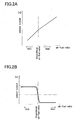
- Fig. 2A is a graph showing an output characteristic of the upstream air-fuel ratio sensor 216a shown in Fig. 1 .
- Fig. 2B is a graph showing an output characteristic of the downstream air-fuel ratio sensor 216b shown in Fig. 1 .
- the upstream air-fuel ratio sensor 216a is an entire-region type air-fuel ratio sensor having a relatively linear output characteristic within a wide air-fuel ratio range. Specifically, this upstream air-fuel ratio sensor 216a is formed by a limiting current type oxygen concentration sensor.
- the downstream air-fuel ratio sensor 216b is an air-fuel ratio sensor having an output characteristic in which an output is substantially fixed on the rich and lean sides of a theoretical air-fuel ratio whereas the output is radically changed around the theoretical air-fuel ratio.
- the downstream air-fuel ratio sensor 216b is formed by a solid electrolyte type zirconium oxygen sensor.
- the exhaust temperature sensor 217 is installed on the upstream side in the flowing direction of the exhaust gas relative to the upstream air-fuel ratio sensor 216a in the exhaust passage 16. This exhaust temperature sensor 217 is formed so as to generate an output in accordance with a temperature of the exhaust gas flowing in the exhaust passage 16.
- the stroke sensor 218 is a linear sensor for generating an output in accordance with a relative position of the cylinder block 11 to the crankcase 13, and is provided so as to be stretched over the cylinder block 11 and the crankcase 13.
- the accelerator press-down degree sensor 219 is formed so as to output a signal corresponding to an operation amount of an accelerator pedal 221 operated by the driver (accelerator operation amount Accp).
- An alarm device 222 provided with an alarm indicating lamp or the like is provided at a position where the alarm device can easily catch eyes of the driver.
- a target air-fuel ratio is set based on the throttle valve aperture TA or the like.
- This target air-fuel ratio is generally set to be the theoretical air-fuel ratio. Meanwhile, at the time of acceleration, etc., the target air-fuel ratio can be set to be a value slightly shifted from the theoretical air-fuel ratio to the rich or lean side, according to need.
- failure diagnosis of the upstream air-fuel ratio sensor 216a and the downstream air-fuel ratio sensor 216b is performed once per one trip (from one start of the engine 1 to stop thereof).
- the target air-fuel ratio is controlled so that it changes in a rectangular waveform between a value shifted from the theoretical air-fuel ratio to the rich side and a value shifted from the theoretical air-fuel ratio to the lean side (so-called air-fuel ratio active control).
- the above air-fuel ratio active control is also performed.
- a basic value of a fuel amount jetted from the injector 127 (basic fuel jet amount) is acquired.
- the basic fuel jet amount is feedback corrected based on outputs from the upstream air-fuel ratio sensor 216a and the downstream air-fuel ratio sensor 216b, so that an actual fuel jet amount from the injector 127 (command fuel jet amount) is acquired.
- air-fuel ratio learning for acquiring the learning correction coefficient at the time of the above open-loop control is performed.
- the OBD of an intake and exhaust system such as the upstream catalyst converter 161, the upstream air-fuel ratio sensor 216a, the downstream air-fuel ratio sensor 216b, and a canister purge system (such as the purge flow passage 156 or the purge control valve 157) is performed by the ECU 200 (CPU 201).
- the catalyst OBD is performed as follows.
- the air-fuel ratio of the fuel-mixing air is forcibly changed into a rectangular waveform.
- the air-fuel ratio of the fuel-mixing air is set to be a predetermined lean air-fuel ratio for a predetermined time.
- oxygen is absorbed by the ternary catalyst of the upstream catalyst converter 161 up to a limit of an absorbing ability.
- the air-fuel ratio of the fuel-mixing air is forcibly changed to a predetermined rich air-fuel ratio.
- the air-fuel ratio detected by the downstream air-fuel ratio sensor 216b is changed to the rich ratio after maintained to be the theoretical air-fuel ratio for a fixed time ⁇ t.
- a maximum oxygen absorption amount in the ternary catalyst of the upstream catalyst converter 161 is determined based on a difference ⁇ (A/F) between the theoretical air-fuel ratio and the rich air-fuel ratio, the time ⁇ t, and an intake air amount of this time. By the acquired value of the maximum oxygen absorption amount, deterioration of the upstream catalyst converter 161 is determined.
- the sensor OBD is performed as follows.
- the air-fuel ratio of the fuel-mixing air is forcibly changed into a rectangular waveform.
- presence of failure of the upstream air-fuel ratio sensor 216a or the downstream air-fuel ratio sensor 216b is determined based on whether or not output waveforms rightly following the air-fuel ratio change are generated.
- trouble determination of the canister purge system is performed based on an output change in the upstream air-fuel ratio sensor 216a when opening and closing of the purge control valve 157 is controlled and purge is controlled to be turned on/off.
- the mechanical compression ratio, the actual compression ratio, and the expansion ratio are controlled based on the operation state of the engine 1 such as a warming-up state and a load state.
- the actual compression ratio is a value determined from actual stroke volume from actual start of a compression operation to arrival of the piston 112 to the top dead center, and clearance volume (volume of the combustion chamber CC with the piston 112 at the top dead center).
- the clearance volume is determined in accordance with a setting state of the mechanical compression ratio.
- the expansion ratio is a ratio of volume at the end of expansion in an expansion stroke and the clearance volume.
- the clearance volume is determined in according with the setting state of the mechanical compression ratio.
- the expansion ratio is variable according to the opening timing of the exhaust valve 124. For example, when the opening timing of the exhaust valve 124 is advanced in order to warm up the upstream catalyst converter 161 at an early stage, so that the temperature of the exhaust gas may be increased. When the opening timing of the exhaust valve 124 is delayed as much as possible, engine thermal efficiency can be enhanced.
- the mechanical compression ratio is set to be high and the opening timing of the exhaust valve 124 is delayed as much as possible, so that the expansion ratio is set to be high (such as about 26) and the engine thermal efficiency is enhanced, and on the other hand, the closing timing of the intake valve 123 is delayed and the actual compression ratio is set to be low
- the mechanical compression ratio and the expansion ratio are set to be high, whereas the closing timing of the intake valve 123 is delayed.
- the actual compression ratio is set to be substantially fixed within a range of a low load or high load of the engine.
- variable compression ratio mechanism 14 the variable intake valve timing device 125, and the variable exhaust valve timing device 126 are controlled so that the mechanical compression ratio and the expansion ratio in the specific OBD are (substantially) fixedly maintained.
- execution of the specific OBD is permitted.
- control system of the compression ratio and the expansion ratio includes the variable compression ratio mechanism 14, the variable intake valve timing device 125, the variable exhaust valve timing device 126, the intake cam position sensor 213a, the exhaust cam position sensor 213b, and the stroke sensor 218.
- this is called as the “compression ratio control system”.
- compression ratio control system can also be called as the “expansion ratio control system”.
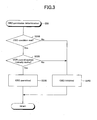
- Fig. 3 is a flowchart showing the first specific example of a determination routine for determining whether or not one OBD is permitted.
- the CPU 201 executes an OBD condition determination routine 300 shown in Fig. 3 at each predetermined timing.
- Step 310 it is determined whether or not an execution condition of one specific OBD (such as a catalyst OBD condition) is met.
- the catalyst OBD condition is that after warming up the engine 1 (cooling water temperature Tw ⁇ Tw0), a change amount of the throttle valve aperture TA per unit time is not more than a predetermined amount, vehicle speed is not less than predetermined speed, and the intake air flow rate is not more than a predetermined rate (intake air flow rate to the extent that so-called "blow-by" is not generated in the upstream catalyst converter 161).
- Step 320 it is determined whether or not the compression ratio control system normally works. Normality determination of this compression ratio control system is performed as follows.
- a catalyst temperature does not quickly follow changes in the actual compression ratio and the expansion ratio. Because of this, merely poor responsiveness of the variable compression ratio mechanism 14 and the stroke sensor 218 does not cause degradation in precision of the catalyst OBD. Therefore, in the case where execution of the OBD condition determination routine 300 of this time relates to condition determination of the catalyst OBD, even when the above (1) is met but (2) and (3) are not met, it is not determined that the failure is generated in the compression ratio control system (Yes in Step 320).
- the execution of the OBD condition determination routine 300 of this time relates to the sensor OBD or the canister purge system OBD, when the above (1) or (4) is met, it is determined that the failure is generated in the compression ratio control system (No in Step 320).
- Step 320 In the case where it is determined that the compression ratio control system normally works (Yes in Step 320), the processing advances to Step 330, the OBD is permitted, and the present routine is once finished. On the other hand, in the case where it is determined that the failure is generated in the compression ratio control system (No in Step 320), the processing advances to Step 340, the OBD is inhibited, and the present routine is once finished.
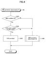
- Fig. 4 is a flowchart showing the second specific example of the determination routine for determining whether or not one OBD is permitted.
- the CPU 201 executes an OBD condition determination routine 400 shown in Fig. 4 at each predetermined timing.
- Step 410 it is determined whether or not an execution condition of one specific OBD is met as well as the above Step 310.
- the processing advances to Step 420, and it is determined whether or not the compression ratio control system normally works.
- Step 420 In the case where it is determined that the compression ratio control system normally works (Yes in Step 420), the processing advances to Step 430, the OBD is permitted, and the present routine is once finished. On the other hand, in the case where it is determined that the failure is generated in the compression ratio control system (No in Step 420), the processing advances to Step 440. In this Step 440, an OBD condition determination sub-routine 500 shown in Fig. 5 is executed.
- Step 510 a trouble (failure) cause of the compression ratio control system is identified.
- This cause identification is performed as (1) to (4) in the above first specific example.
- the processing advances to Step 520, and it is determined whether or not the sensors such as the compression ratio control system sensors (such as the stroke sensor 218) and the exhaust temperature sensor 217 normally work.
- the actual compression ratio or the expansion ratio can be identified, and the actual compression ratio or the expansion ratio comply with the OBD condition (Yes in Step 410).
- the OBD using an estimated temperature of the catalyst (such as the catalyst OBD and the sensor OBD)
- the processing advances to Step 530, the OBD is permitted, and the routines 500 and 400 are once finished.
- Step 520 Even in the case where some failure is found in the sensors (No in Step 520) but the parameters (such as the temperature of the exhaust gas) required for the OBD can be identified (acquired), there is no problem in executing the OBD. Thus, in the case where determination in Step 520 is "No", the processing advances to Step 540, and it is determined whether or not such parameters can be identified (acquired). For example, in the OBD using the temperature of the exhaust gas or the estimated temperature of the catalyst, in the case where at least the exhaust temperature sensor 217 normally works, it is determined that the parameters can be identified (Yes in Step 540). It should be noted that normality determination of this exhaust temperature sensor 217 can be performed based on history or the like of the sensor outputs from the start of the engine 1, for example.
- Step 540 In the case where it is determined that the parameters can be identified (Yes in Step 540), the processing advances to Step 530, the OBD is permitted, and the routines 500 and 400 are once finished. On the other hand, in the case where it is determined that the parameters cannot be identified (No in Step 540), the processing advances to Step 550, the OBD is inhibited, and the routines 500 and 400 are once finished.
- a compression ratio acquiring unit (expansion ratio acquiring unit) of the present invention is realized by the ECU 200 (CPU 201) and the stroke sensor 218.
- a compression ratio control system failure detecting unit of the present invention is realized by the ECU 200 (CPU 201), the stroke sensor 218, and other sensors.
- a temperature acquiring unit of the present invention is realized by the ECU 200 (CPU 201), the exhaust temperature sensor 217, and other sensors.
- an intake and exhaust system determining unit and an intake and exhaust system determination permitting unit of the present invention are realized by the ECU 200 (CPU 201).
- the above embodiment is to only illustrate specific configuration examples of the present invention that the applicant thinks the best at the time of filing the present application. From the beginning, the present invention is not limited to the above embodiment at all. Therefore, the specific configurations shown in the above embodiment can be variously modified within a range not changing essential parts of the present invention, as a matter of course.
- elements whose operations and functions are expressed among the elements forming the means for solving the problem of the present invention include any structures capable of realizing the operations and the functions in addition to the specific structures disclosed in the above embodiment and the modifications.
Landscapes
- Engineering & Computer Science (AREA)
- Chemical & Material Sciences (AREA)
- Combustion & Propulsion (AREA)
- Mechanical Engineering (AREA)
- General Engineering & Computer Science (AREA)
- Output Control And Ontrol Of Special Type Engine (AREA)
- Combined Controls Of Internal Combustion Engines (AREA)
- Exhaust Gas After Treatment (AREA)
Description
- The present invention relates to an engine system control device to be applied to an engine system (system provided with an engine such as an automobile). The present invention particularly relates to an engine system control device in the case where the engine has a variable compression ratio mechanism capable of changing a compression ratio.
- In an engine system, state determination of an intake and exhaust system, that is, failure diagnosis is performed by an engine electronic control unit (hereinafter, called as the "ECU"). Such on-board diagnosis (OBD) of the intake and exhaust system includes catalyst failure diagnosis, exhaust gas sensor failure diagnosis, and canister purge system failure diagnosis.
- For example, in an exhaust passage for this type of system, a catalyst for purifying an exhaust gas is placed. This catalyst is deteriorated due to harmful components (such as lead and sulfur) in fuel and excessive heating. When the catalyst is deteriorated, an exhaust gas purifying ratio is degraded, and exhaust emission is increased. Thus, various devices for determining deterioration of the catalyst are conventionally proposed (such as Japanese Patent Application Publication No. 1993(H5)-133264 and 2004-28029).
- As this kind of catalyst, a so-called ternary catalyst is widely used. This ternary catalyst has a function called an oxygen absorption function or an oxygen storage function. In the case where an air-fuel ratio of the fuel-mixing air is lean, such a function is to reduce NOx (nitrogen oxide) in the exhaust gas and absorb (store) oxygen taken from NOx inside. Meanwhile, in the case where the air-fuel ratio of the fuel-mixing air is rich, the function is to release the absorbed oxygen for oxidation of unburned components such as HC and CO in the exhaust gas.
- Thus, the more a maximum value of an oxygen amount to be absorbed by the ternary catalyst (hereinafter, called as the "oxygen absorption amount") is, the higher a purifying ability of the ternary catalyst is. Therefore, a deterioration state of the ternary catalyst can be determined by the maximum value of the oxygen absorption amount (hereinafter, called as the "maximum oxygen absorption amount").
- In a catalyst deterioration degree detection device disclosed in Japanese Patent Application Publication No.
1993(H5)-133264 - Deterioration determination of the ternary catalyst (calculation of the maximum oxygen absorption amount) with such a configuration is performed as follows. Firstly, the air-fuel ratio of the fuel-mixing air supplied into a cylinder of an engine is set to be a predetermined lean air-fuel ratio for a predetermined time. Thereby, oxygen is absorbed by the ternary catalyst up to a limit of an absorbing ability. After that, the air-fuel ratio of the fuel-mixing air is forcibly changed to a predetermined rich air-fuel ratio. Then, the air-fuel ratio detected by the second air-fuel ratio sensor is changed to the rich ratio after maintained to be a theoretical air-fuel ratio only for a fixed time Δt. The maximum oxygen absorption amount is determined based on a difference Δ (A/F) between the theoretical air-fuel ratio and the rich air-fuel ratio, the time Δt, and an intake air amount of this time.
- This maximum oxygen absorption amount is changed even with a temperature of the ternary catalyst. Specifically, when the temperature of the ternary catalyst is increased, the maximum oxygen absorption amount is increased. Thus, when the deterioration determination of the catalyst is performed based on the maximum oxygen absorption amount calculated without considering the temperature of the catalyst, there is a problem that determination precision is not favorable. In a catalyst deterioration degree detection device disclosed in Japanese Patent Application Publication No.
2004-28029 - In order to control the air-fuel ratio of the engine, so-called air-fuel ratio feedback control is generally performed. This control is performed based on an output of an exhaust gas sensor (air-fuel ratio sensor) placed in an exhaust passage. In general, this exhaust gas sensor is an oxygen sensor for generating an output in accordance with oxygen concentration in the exhaust gas. This exhaust gas sensor is provided on the upstream side and/or the downstream side in the flowing direction of the exhaust gas relative to the catalyst for purifying the exhaust gas.
- In general, as the exhaust gas sensor provided on the downstream side relative to the catalyst (second air-fuel ratio sensor described above), a solid electrolyte type oxygen sensor having an output characteristic in which an output is substantially fixed on the rich and lean sides of the theoretical air-fuel ratio whereas the output is radically changed around the theoretical air-fuel ratio is used. As the exhaust gas sensor provided on the upstream side relative to the catalyst (first air-fuel ratio sensor described above), the solid electrolyte type oxygen sensor or a limiting current type oxygen concentration sensor having a relatively linear output characteristic within a wide air-fuel ratio range is used.
- When failure such as the deterioration is generated in the exhaust gas sensor, there is a fear that air-fuel ratio control of the engine is not properly performed. The exhaust gas sensor is also used to calculate the maximum oxygen absorption amount for the deterioration determination of the catalyst as described above. Therefore, when the failure such as the deterioration is generated in the exhaust gas sensor, the deterioration determination of the catalyst cannot be accurately performed.
- Thus, a device for diagnosing the failure of this exhaust gas sensor is conventionally proposed (for example, refer to Japanese Patent Application Publication No.
2003-254135 2004-225684 2007-16712 2004-225684 -
JP H06 159153 A engine 1 is discriminated based on detected signals from various kinds of sensors, and the target valve opening value of theEGR valve 16 according to the discriminated result is calculated and set. These main sensors are a throttle valve opening sensor 4, an intake pipe inner absolute pressure sensor 7, an engine cooling water temperature sensor 8, an engine rotational speed sensor 9, a catalytic temperature sensor 30 and the like. The EGR control is not appropriately performed if only one of these sensors is abnormal. -
EP 1 464 814 A2 - There are known engines provided with a variable compression ratio mechanism capable of changing a compression ratio (for example, refer to Japanese Patent Application Publication No.
2003-206771 2004-156541 2005-69204 2006-161583 2007-224927 - The mechanical compression ratio is a value determined by dividing the sum of clearance volume (combustion chamber volume at a piston top dead center) and volume of a piston stroke by the clearance volume, and is also called as a nominal compression ratio or a geometrical compression ratio. The mechanical compression ratio can be changed for example by relatively moving a crankcase on which a crankshaft is rotatably supported, and a cylinder block with an upper end thereof to which a cylinder head is fixed along an axis of a cylinder. Alternatively, the mechanical compression ratio can be changed by, in the case where a connecting rod (member for coupling a piston and the crankshaft) is bendable, changing a bent state of this connecting rod.
- The actual compression ratio is an effective compression ratio to the intake air, and typically a value determined by dividing the combustion chamber volume at the time of starting compression of the intake air by the combustion chamber volume at the time of finishing the compression. This actual compression ratio can be changed in accordance with the above change in the mechanical compression ratio. This actual compression ratio can be changed by varying action timing of an intake valve and an exhaust valve together with the change in the mechanical compression ratio or in place of this change.
- It should be noted that an expansion ratio can also be changed by the change in the mechanical compression ratio. The expansion ratio is a ratio of volume at the end of expansion in an expansion stroke to volume at the beginning of the expansion (=clearance volume). It should be noted that this expansion ratio can be changed by changing opening and closing timing of the exhaust valve.
- Further, by changing opening and closing timing of the intake and exhaust valves, the mechanical compression ratio, the actual compression ratio, and the expansion ratio can be independently set and changed (for example, refer to Japanese Patent Application Publication No.
2007-303423 2008-19799 2008-157128 - In the case where such a mechanism for changing the compression ratio and the expansion ratio or a control device thereof in the engine is broken, a combustion state of the fuel-mixing air and the temperature of the exhaust gas cannot be controlled, so that parameters (such as the temperature of a member to be diagnosed or the exhaust gas) required for the on-board diagnosis of the intake and exhaust system can become unknown. Therefore, in this case, it may be difficult to perform the on-board diagnosis precisely.
- An object of the present invention is to improve precision of the on-board diagnosis of the intake and exhaust system in an engine system provided with an engine in which the compression ratio or the expansion ratio is variable. This object is achieved by an engine system control device according to
claim 1. Further advantageous developments are subject-matters of the dependent claims. - An engine system control device of the present invention (hereinafter, simply referred to as the "control device") is applied to an engine system provided with an engine having a variable compression ratio mechanism capable of changing a compression ratio. It should be noted that this engine includes an engine in which an expansion ratio is variable. That is, this engine may include an engine in which a mechanical compression ratio, an actual compression ratio, and the expansion ratio can be independently set and changed by changing the mechanical compression ratio and opening and closing timing of intake and exhaust valves.
- This control device is provided with a compression ratio acquiring unit, a compression ratio control system failure detecting unit, an intake and exhaust system determining unit, and an intake and exhaust system determination permitting unit. It should be noted that the term "unit" may be called as a term "means" (such as the "compression ratio acquiring means", or the like, the same is applied to the remaining similar items).
- The compression ratio acquiring unit is configured to acquire a setting state of the compression ratio by the variable compression ratio mechanism (the term "acquiring" includes detection and estimation, the same is applied to the remaining similar items).
- The compression ratio control system failure detecting unit is configured to detect generation of failure in a compression ratio control system including the variable compression ratio mechanism and the compression ratio acquiring unit.
- The intake and exhaust system determining unit is configured to determine a state of a member placed in an intake and exhaust system of the engine. For example, this intake and exhaust system determining unit may be configured to determine the state of the member placed in a passage of an exhaust gas discharged from the engine (such as a catalyst or an exhaust gas sensor).
- The intake and exhaust system determination permitting unit is configured to permit determination by the intake and exhaust system determining unit.
- As a characteristic of the present invention, the intake and exhaust system determination permitting unit is configured to inhibit the determination by the intake and exhaust system determining unit, in the case where the compression ratio control system failure detecting unit detects the generation of the failure. According to the invention the intake and exhaust system determination permitting unit is configured to permit the determination by the intake and exhaust system determining unit, in the case where the compression ratio control system failure detecting unit detects the generation of the failure but the setting state of the compression ratio is acquirable.
- When the control device is further provided with a temperature acquiring unit for acquiring a temperature of the exhaust gas or the member, the intake and exhaust system determination permitting unit may be configured to permit the determination by the intake and exhaust system determining unit in the case where the compression ratio control system failure detecting unit detects the generation of the failure but the temperature is acquirable by the temperature acquiring unit.
- In the engine system control device of the present invention provided with the above configuration, in the case where the compression ratio control system normally works, and a predetermined determination condition is met, the determination of the state of the member (such as catalyst OBD or exhaust gas sensor OBD) is performed. Meanwhile, in the case where the failure is generated in the compression ratio control system and the setting state of the compression ratio or the expansion ratio becomes unknown, the determination of the state of the member is inhibited.
- However, in the case where the failure is generated in the compression ratio control system but the setting state of the compression ratio is acquirable or the temperature is acquirable, the determination of the state of the member is favorably performed. Therefore, in these occasions, the determination can be permitted.
- As described above, according to the present invention, the on-board diagnosis of the intake and exhaust system (on-board diagnosis influenced by a state of the exhaust gas in particular) is properly performed in the engine system provided with the engine in which the compression ratio or the expansion ratio is variable. Therefore, precision of the diagnosis can be improved more than that of the conventional examples.
-
-
Fig. 1 is a schematic configuration diagram of major parts of an engine system (such as a vehicle) to which the present invention is applied; -
Fig. 2A is a graph showing an output characteristic of an upstream air-fuel ratio sensor shown inFig. 1 ; -
Fig. 2B is a graph showing an output characteristic of a downstream air-fuel ratio sensor shown inFig. 1 ; -
Fig. 3 is a flowchart showing a first specific example of a determination routine for determining whether or not one OBD is permitted; -
Fig. 4 is a flowchart showing a second specific example of the determination routine for determining whether or not one OBD is permitted; -
Fig. 5 is a flowchart showing the second specific example of the determination routine for determining whether or not one OBD is permitted; -
Fig. 6 is a schematic configuration diagram of major parts in one modification of the engine system shown inFig. 1 ; -
Fig. 7 is a schematic configuration diagram of major parts in one of other modifications of the engine system shown inFig. 1 ; and -
Fig. 8 is a schematic configuration diagram of major parts in further one of other modifications of the engine system shown inFig. 1 . - Hereinafter, an embodiment of the present invention (embodiment that the applicant thinks the best at the time of filing the present application) will be described with reference to the drawings.
- It should be noted that the following description relating to the embodiment is only to specifically describe just one concrete example for embodying the present invention within a practicable range in order to meet legal description requirement of the specification (descriptive requirement and enablement requirement). Therefore, as described below, it is a matter of course that the present invention is not at all limited to specific configurations of the embodiment described below. When modifications of the embodiment are inserted in the middle of the description of the embodiment, understanding of consistent description of the embodiment is prevented. Thus, the modifications will be collectively described in the last part.
-
Fig. 1 is a schematic configuration diagram of major parts of an engine system S (such as a vehicle) to which the present invention is applied. This engine system S is provided with anengine 1, and acontrol device 2 serving as one embodiment of the present invention. It should be noted that a side sectional view of theengine 1 by plane orthogonal to the cylinder arranging direction is shown inFig. 1 . - In the present embodiment, the
engine 1 is formed so that a mechanical compression ratio is variable within a predetermined range. By changing the mechanical compression ratio and timing of intake and exhaust valves, theengine 1 is formed so that the mechanical compression ratio, an actual compression ratio, and an expansion ratio can be substantially independently set and changed. - Specifically, the
engine 1 is provided with acylinder block 11, acylinder head 12, acrankcase 13, and a variablecompression ratio mechanism 14. Anintake passage 15 and anexhaust passage 16 are connected to theengine 1. Hereinafter, detailed configurations of these parts will be described. - A plurality of cylinder bores 111 is arranged in a row along the cylinder arranging direction in the
cylinder block 11. Apiston 112 is housed inside each of the cylinder bores 111 reciprocably along an axis of the cylinder bore 111 (hereinafter, this axis is referred to as the "cylinder axis CCA"). - The
cylinder head 12 is jointed to an upper end of thecylinder block 11, that is, an end of thecylinder block 11 on the top dead center side of thepiston 112. Thecylinder head 12 is fixed to thecylinder block 11 by bolts or the like (not shown). - A plurality of concave portions is provided at positions corresponding to upper ends of the cylinder bores 111 in a lower end of the
cylinder head 12. In the state where thecylinder head 12 is jointed and fixed to thecylinder block 11, a combustion chamber CC is formed by a space inside the cylinder bore 111 on the upper side of a top surface of the piston 112 (on the side of the cylinder head 12), and a space inside (below) the above concave portion. - An
intake port 121 and anexhaust port 122 are formed in thecylinder head 12 so as to communicate with the combustion chamber CC. Thecylinder head 12 is provided with anintake valve 123, anexhaust valve 124, a variable intakevalve timing device 125, and a variable exhaustvalve timing device 126. - The
intake valve 123 is a valve for controlling a communication state between theintake port 121 and the combustion chamber CC. Theexhaust valve 124 is a valve for controlling a communication state between theexhaust port 122 and the combustion chamber CC. The variable intakevalve timing device 125 and the variable exhaustvalve timing device 126 are formed so as to change the actual compression ratio and the expansion ratio by changing opening and closing timing of theintake valve 123 and theexhaust valve 124. Since specific configurations of the variable intakevalve timing device 125 and the variable exhaustvalve timing device 126 are already known, more detailed description will be omitted in the present specification. - The
cylinder head 12 is also provided with aninjector 127. Theinjector 127 is formed so as to jet fuel to be supplied into the combustion chamber CC into theintake port 121. - A
crankshaft 131 is arranged in parallel to the cylinder arranging direction and rotatably supported in thecrankcase 13. Thecrankshaft 131 is coupled to thepiston 112 via a connectingrod 132 so as to be rotated and driven based on reciprocating movement of thepiston 112 along the cylinder axis CCA. - In the present embodiment, the variable
compression ratio mechanism 14 is formed so as to change the mechanical compression ratio within the above range by relatively moving a joint body of thecylinder block 11 and thecylinder head 12 relative to thecrankcase 13 along the cylinder axis CCA. This variablecompression ratio mechanism 14 is provided with the same configuration as a variable compression ratio mechanism described in Japanese Patent Application Publication No.2003-206771 - The variable
compression ratio mechanism 14 is provided with acoupling mechanism 141, and adrive mechanism 142. Thecoupling mechanism 141 is formed so as to couple thecylinder block 11 and thecrankcase 13 movably relative to each other along the cylinder axis CCA. Thedrive mechanism 142 is provided with a motor, a gear mechanism, and the like. Thisdrive mechanism 142 is formed so as to move thecylinder block 11 and thecrankcase 13 relative to each other along the cylinder axis CCA. - The
intake passage 15 including an intake manifold, a surge tank, and the like is connected to theintake port 121. Athrottle valve 151 is placed in theintake passage 15. Thethrottle valve 151 is formed so as to be rotated and driven by athrottle valve actuator 152 formed by a DC motor. - A
fuel tank 153 is connected to theinjector 127 via a fuel supply path (not shown). Avapor discharge port 153a for discharging "vaporized fuel" (hereinafter, called as the "vapor") is provided in an upper end of thefuel tank 153. The vapor discharged from thefuel tank 153 via thevapor discharge port 153a is absorbed by acanister 154. - The
canister 154 is a known charcoal canister formed so as to absorb a predetermined amount of vapor. Thecanister 154 is provided with atank port 154a, and apurge port 154b. Thetank port 154a is connected to thevapor discharge port 153a of thefuel tank 153 via avapor collecting pipe 155. Thepurge port 154b is connected to a position of theintake passage 15 between thethrottle valve 151 and theinjector 127 via apurge flow passage 156. Apurge control valve 157 serving as an electromagnetic open and close valve is placed in thepurge flow passage 156. - The
exhaust passage 16 including an exhaust manifold is connected to theexhaust port 122. Theexhaust passage 16 is a passage of an exhaust gas discharged from the combustion chamber CC via theexhaust port 122. - An
upstream catalyst converter 161 and adownstream catalyst converter 162 are placed in theexhaust passage 16. In the present embodiment, theupstream catalyst converter 161 and thedownstream catalyst converter 162 are provided with ternary catalysts having an oxygen absorption function inside thereof, and formed so as to purify HC, CO, and NOx in the exhaust gas. - The
control device 2 is formed so as to control operation of theengine 1 provided with the above configuration, determine (diagnose) states of the parts of the engine system S, and appropriately display determination (diagnosis) results to a driver. Hereinafter, a specific configuration of thecontrol device 2 of the present embodiment will be described. - The
control device 2 is provided with an ECU (electronic control unit) 200. TheECU 200 is provided with aCPU 201, aROM 202, aRAM 203, abackup RAM 204, aninterface 205, and abus 206. TheCPU 201, theROM 202, theRAM 203, thebackup RAM 204, and theinterface 205 are connected to each other by thebus 206. - Routines (programs) to be executed by the
CPU 201, tables (look-up tables, maps), parameters, and the like are preliminarily stored in theROM 202. TheRAM 203 is formed so as to temporarily store data according to need when theCPU 201 executes the routines. Thebackup RAM 204 is formed so as to store the data when theCPU 201 executes the routines in a power activation state, and to maintain this stored data even after power shut-down. - The
interface 205 is electrically connected to various sensors described below, and formed so as to transmit signals from these sensors to theCPU 201. Theinterface 205 is electrically connected to operating units such as the variable intakevalve timing device 125, the variable exhaustvalve timing device 126, theinjector 127, and thedrive mechanism 142, and formed so as to transmit operation signals for operating these operating units from theCPU 201 to these operating units. - That is, the
ECU 200 is formed so as to receive the signals from the various sensors via theinterface 205, and send the above operation signals toward the operating units in accordance with calculation results of theCPU 201 based on the signals. - The engine system S is provided with the various sensors such as a cooling
water temperature sensor 211, a crankposition sensor 212, an intakecam position sensor 213a, an exhaustcam position sensor 213b, anair flow meter 214, athrottle position sensor 215, an upstream air-fuel ratio sensor 216a, a downstream air-fuel ratio sensor 216b, anexhaust temperature sensor 217, astroke sensor 218, and an accelerator press-down degree sensor 219. - The cooling
water temperature sensor 211 is installed in thecylinder block 11. This coolingwater temperature sensor 211 is formed so as to output a signal corresponding to a temperature of cooling water (cooling water temperature Tw) in thecylinder block 11. - The crank
position sensor 212 is installed in thecrankcase 13. This crankposition sensor 212 is formed so as to output a waveform signal having a pulse in accordance with a rotation angle of thecrankshaft 131. Specifically, the crankposition sensor 212 is formed so as to output a signal having a narrow pulse for every time when thecrankshaft 131 is rotated by 10° and having a wide pulse for every time when thecrankshaft 131 is rotated by 360°. That is, the crankposition sensor 212 is formed so as to output a signal corresponding to the engine rotation number Ne. - The intake
cam position sensor 213a and the exhaustcam position sensor 213b are installed in thecylinder head 12. The intakecam position sensor 213a is formed so as to output a waveform signal having a pulse in accordance with a rotation angle of an intake cam shaft (not shown: included in the variable intake valve timing device 125) for reciprocatingly moving theintake valve 123. The exhaustcam position sensor 213b is similarly formed so as to output a waveform signal having a pulse in accordance with a rotation angle of an exhaust cam shaft (not shown). - The
air flow meter 214 and thethrottle position sensor 215 are installed in theintake passage 15. Theair flow meter 214 is formed so as to output a signal corresponding to a mass flow rate of the intake air flowing in the intake passage 15 (intake air flow rate Ga). Thethrottle position sensor 215 is formed so as to output a signal corresponding to a rotation phase of the throttle valve 151 (throttle valve aperture TA). - The upstream air-
fuel ratio sensor 216a and the downstream air-fuel ratio sensor 216b are installed in theexhaust passage 16. The upstream air-fuel ratio sensor 216a is arranged on the upstream side in the flowing direction of the exhaust gas relative to theupstream catalyst converter 161. The downstream air-fuel ratio sensor 216b is arranged between theupstream catalyst converter 161 and thedownstream catalyst converter 162, that is, on the downstream side in the flowing direction of the exhaust gas relative to theupstream catalyst converter 161 and on the upstream side relative to thedownstream catalyst converter 162. -
Fig. 2A is a graph showing an output characteristic of the upstream air-fuel ratio sensor 216a shown inFig. 1 .Fig. 2B is a graph showing an output characteristic of the downstream air-fuel ratio sensor 216b shown inFig. 1 . - As shown in
Fig. 2A , the upstream air-fuel ratio sensor 216a is an entire-region type air-fuel ratio sensor having a relatively linear output characteristic within a wide air-fuel ratio range. Specifically, this upstream air-fuel ratio sensor 216a is formed by a limiting current type oxygen concentration sensor. As shown inFig. 2B , the downstream air-fuel ratio sensor 216b is an air-fuel ratio sensor having an output characteristic in which an output is substantially fixed on the rich and lean sides of a theoretical air-fuel ratio whereas the output is radically changed around the theoretical air-fuel ratio. Specifically, the downstream air-fuel ratio sensor 216b is formed by a solid electrolyte type zirconium oxygen sensor. - Referring to
Fig. 1 again, theexhaust temperature sensor 217 is installed on the upstream side in the flowing direction of the exhaust gas relative to the upstream air-fuel ratio sensor 216a in theexhaust passage 16. Thisexhaust temperature sensor 217 is formed so as to generate an output in accordance with a temperature of the exhaust gas flowing in theexhaust passage 16. - The
stroke sensor 218 is a linear sensor for generating an output in accordance with a relative position of thecylinder block 11 to thecrankcase 13, and is provided so as to be stretched over thecylinder block 11 and thecrankcase 13. - The accelerator press-
down degree sensor 219 is formed so as to output a signal corresponding to an operation amount of anaccelerator pedal 221 operated by the driver (accelerator operation amount Accp). Analarm device 222 provided with an alarm indicating lamp or the like is provided at a position where the alarm device can easily catch eyes of the driver. - Hereinafter, an outline of actions of the engine system S of the present embodiment will be described.
- A target air-fuel ratio is set based on the throttle valve aperture TA or the like. This target air-fuel ratio is generally set to be the theoretical air-fuel ratio. Meanwhile, at the time of acceleration, etc., the target air-fuel ratio can be set to be a value slightly shifted from the theoretical air-fuel ratio to the rich or lean side, according to need.
- When a predetermined sensor OBD condition is met, failure diagnosis (sensor OBD) of the upstream air-
fuel ratio sensor 216a and the downstream air-fuel ratio sensor 216b is performed once per one trip (from one start of theengine 1 to stop thereof). During this sensor OBD, the target air-fuel ratio is controlled so that it changes in a rectangular waveform between a value shifted from the theoretical air-fuel ratio to the rich side and a value shifted from the theoretical air-fuel ratio to the lean side (so-called air-fuel ratio active control). - Similarly, in the case where deterioration determination of the upstream catalyst converter 161 (catalyst OBD) is performed under a predetermined operation state during normal operation, the above air-fuel ratio active control is also performed.
- Based on the target air-fuel ratio set as described above, the intake air flow rate Ga, and the like, a basic value of a fuel amount jetted from the injector 127 (basic fuel jet amount) is acquired.
- In the case where a predetermined feedback control condition is not met, for example, in the case where the upstream air-
fuel ratio sensor 216a and the downstream air-fuel ratio sensor 216b are not sufficiently warmed up immediately after the start of theengine 1 or the like, open-loop control based on the basic fuel jet amount is performed (in this open-loop control, learning control based on a learning correction coefficient can be performed). - In the case where the feedback control condition is met, the basic fuel jet amount is feedback corrected based on outputs from the upstream air-
fuel ratio sensor 216a and the downstream air-fuel ratio sensor 216b, so that an actual fuel jet amount from the injector 127 (command fuel jet amount) is acquired. Based on the outputs from the upstream air-fuel ratio sensor 216a and the downstream air-fuel ratio sensor 216b, air-fuel ratio learning for acquiring the learning correction coefficient at the time of the above open-loop control is performed. - Since specific contents of such air-fuel ratio control are already known, more detailed description will be omitted in the present specification.
- The OBD of an intake and exhaust system such as the
upstream catalyst converter 161, the upstream air-fuel ratio sensor 216a, the downstream air-fuel ratio sensor 216b, and a canister purge system (such as thepurge flow passage 156 or the purge control valve 157) is performed by the ECU 200 (CPU 201). - For example, the catalyst OBD is performed as follows.
- By the above air-fuel ratio active control, the air-fuel ratio of the fuel-mixing air is forcibly changed into a rectangular waveform.
- Firstly, the air-fuel ratio of the fuel-mixing air is set to be a predetermined lean air-fuel ratio for a predetermined time. Thereby, oxygen is absorbed by the ternary catalyst of the
upstream catalyst converter 161 up to a limit of an absorbing ability. After that, the air-fuel ratio of the fuel-mixing air is forcibly changed to a predetermined rich air-fuel ratio. Then, the air-fuel ratio detected by the downstream air-fuel ratio sensor 216b is changed to the rich ratio after maintained to be the theoretical air-fuel ratio for a fixed time Δt. - A maximum oxygen absorption amount in the ternary catalyst of the
upstream catalyst converter 161 is determined based on a difference Δ (A/F) between the theoretical air-fuel ratio and the rich air-fuel ratio, the time Δt, and an intake air amount of this time. By the acquired value of the maximum oxygen absorption amount, deterioration of theupstream catalyst converter 161 is determined. - Since specific contents of such catalyst OBD are already known, more detailed description will be omitted in the present specification.
- The sensor OBD is performed as follows.
- By the above air-fuel ratio active control, the air-fuel ratio of the fuel-mixing air is forcibly changed into a rectangular waveform. At this time, presence of failure of the upstream air-
fuel ratio sensor 216a or the downstream air-fuel ratio sensor 216b is determined based on whether or not output waveforms rightly following the air-fuel ratio change are generated. - Since specific contents of such sensor OBD are already known, more detailed description will be omitted in the present specification.
- Further, trouble determination of the canister purge system (canister purge OBD) is performed based on an output change in the upstream air-
fuel ratio sensor 216a when opening and closing of thepurge control valve 157 is controlled and purge is controlled to be turned on/off. - The mechanical compression ratio, the actual compression ratio, and the expansion ratio are controlled based on the operation state of the
engine 1 such as a warming-up state and a load state. - The actual compression ratio is a value determined from actual stroke volume from actual start of a compression operation to arrival of the
piston 112 to the top dead center, and clearance volume (volume of the combustion chamber CC with thepiston 112 at the top dead center). The clearance volume is determined in accordance with a setting state of the mechanical compression ratio. Meanwhile, even when thepiston 112 starts rising in a compression stroke, the compression operation is substantially not performed during the time when theintake valve 123 is opened. The actual compression operation is started from the time when theintake valve 123 is closed. Therefore, in the case where the mechanical compression ratio is fixed, the closing timing of theintake valve 123 is delayed, so that the actual compression ratio is lowered. - The expansion ratio is a ratio of volume at the end of expansion in an expansion stroke and the clearance volume. As described above, the clearance volume is determined in according with the setting state of the mechanical compression ratio. Meanwhile, the expansion ratio is variable according to the opening timing of the
exhaust valve 124. For example, when the opening timing of theexhaust valve 124 is advanced in order to warm up theupstream catalyst converter 161 at an early stage, so that the temperature of the exhaust gas may be increased. When the opening timing of theexhaust valve 124 is delayed as much as possible, engine thermal efficiency can be enhanced. - Therefore, for example, at the time of low-load operation of the engine, the mechanical compression ratio is set to be high and the opening timing of the
exhaust valve 124 is delayed as much as possible, so that the expansion ratio is set to be high (such as about 26) and the engine thermal efficiency is enhanced, and on the other hand, the closing timing of theintake valve 123 is delayed and the actual compression ratio is set to be low - (such as about 11), so that failure combustion such as knocking can be suppressed (so-called high expansion ratio cycle).
- Specifically, for example, according to a decrease in an engine load, the mechanical compression ratio and the expansion ratio are set to be high, whereas the closing timing of the
intake valve 123 is delayed. Thereby, the actual compression ratio is set to be substantially fixed within a range of a low load or high load of the engine. - However, when the mechanical compression ratio and the expansion ratio are changed during the time of executing the OBD(hereinafter, referred to as the "specific OBD", this includes exhaust gas sensor OBD, catalyst OBD, and canister purge system OBD) influenced by a state of the exhaust gas (such as the temperature and composition), there is a fear that precision of the OBD is lowered.
- Specifically, when the mechanical compression ratio and the expansion ratio are changed during the time of executing the specific OBD, a combustion state of the fuel-mixing air and the temperature of the exhaust gas are changed, so that this change influences the outputs of the upstream air-
fuel ratio sensor 216a and the downstream air-fuel ratio sensor 216b, and the change in the temperature of the exhaust gas invites a change in a temperature of theupstream catalyst converter 161 and the oxygen absorption function (oxygen absorption and release characteristic) of theupstream catalyst converter 161 is changed. Particularly, in the OBD of the downstream air-fuel ratio sensor 216b, it is difficult to perform precise OBD unless the oxygen absorption function of theupstream catalyst converter 161 is fixedly maintained. - Therefore, the variable
compression ratio mechanism 14, the variable intakevalve timing device 125, and the variable exhaustvalve timing device 126 are controlled so that the mechanical compression ratio and the expansion ratio in the specific OBD are (substantially) fixedly maintained. Alternatively, in a state that the mechanical compression ratio and the expansion ratio are (substantially) fixedly maintained, execution of the specific OBD is permitted. - In the case where a control system of the compression ratio and the expansion ratio is broken, the combustion state of the fuel-mixing air and the temperature of the exhaust gas cannot be controlled, so that the parameters (such as the temperature of the exhaust gas or members to be diagnosed) required for the specific OBD can become unknown. Therefore, in this case, it may be difficult to perform the specific OBD precisely.
- It should be noted that the above "control system of the compression ratio and the expansion ratio" includes the variable
compression ratio mechanism 14, the variable intakevalve timing device 125, the variable exhaustvalve timing device 126, the intakecam position sensor 213a, the exhaustcam position sensor 213b, and thestroke sensor 218. Hereinafter, this is called as the "compression ratio control system". This "compression ratio control system" can also be called as the "expansion ratio control system". - Next, specific examples of the actions of the
control device 2 according to the present embodiment shown inFig. 1 will be described with using flowcharts. It should be noted that inFig. 3 and following figures showing the flowcharts, Step is abbreviated as "S". - In a first specific example described below, in the case where the failure is generated in the compression ratio control system, the execution of all the specific OBDs is inhibited.
Fig. 3 is a flowchart showing the first specific example of a determination routine for determining whether or not one OBD is permitted. TheCPU 201 executes an OBDcondition determination routine 300 shown inFig. 3 at each predetermined timing. - Firstly, in Step 310, it is determined whether or not an execution condition of one specific OBD (such as a catalyst OBD condition) is met. For example, the catalyst OBD condition is that after warming up the engine 1 (cooling water temperature Tw ≥ Tw0), a change amount of the throttle valve aperture TA per unit time is not more than a predetermined amount, vehicle speed is not less than predetermined speed, and the intake air flow rate is not more than a predetermined rate (intake air flow rate to the extent that so-called "blow-by" is not generated in the upstream catalyst converter 161).
- In the case where the OBD condition is met (Yes in Step 310), the processing advances to Step 320, and it is determined whether or not the compression ratio control system normally works. Normality determination of this compression ratio control system is performed as follows.
- (1) In the case where a difference Δεm between a target mechanical compression ratio εm_t determined by executing a mechanical compression ratio control routine based on the operation state and a mechanical compression ratio acquired value εm_g acquired based on an output of the
stroke sensor 218 exceeds a predetermined time Δεm_err, the failure is generated in the compression ratio control system. - (2) In a case of the above (1), when a period in which a drive current of the motor in the drive mechanism 142 (this may be acquired by the CPU 201) becomes a maximum value exceeds a predetermine time t err, it is estimated that mechanical trouble is generated in the variable
compression ratio mechanism 14. - (3) In a case of the above (1), when the mechanical compression ratio acquired value εm_g is fixed even with a change in the target mechanical compression ratio εm_t, and a period in which the drive current of the motor in the drive mechanism 142 (this may be acquired by the CPU 201) becomes the maximum value does not exceed the predetermine time t err, it is estimated that the failure (such as breaking of wires and troubles) is generated in the
stroke sensor 218. - (4) In the case where a mismatch exceeding a predetermined range is generated between a determined value of the opening and closing timing of the
intake valve 123 and theexhaust valve 124 by executing an actual compression ratio control routine and an expansion ratio control routine based on the operation state, and an acquired value of the opening and closing timing of theintake valve 123 and theexhaust valve 124 based on outputs of the intakecam position sensor 213a and the exhaustcam position sensor 213b, it is estimated that the failure is generated in the variable intakevalve timing device 125 and the variable exhaustvalve timing device 126. - A catalyst temperature does not quickly follow changes in the actual compression ratio and the expansion ratio. Because of this, merely poor responsiveness of the variable
compression ratio mechanism 14 and thestroke sensor 218 does not cause degradation in precision of the catalyst OBD. Therefore, in the case where execution of the OBDcondition determination routine 300 of this time relates to condition determination of the catalyst OBD, even when the above (1) is met but (2) and (3) are not met, it is not determined that the failure is generated in the compression ratio control system (Yes in Step 320). - Meanwhile, the state (such as the composition) of the exhaust gas itself quickly follows the changes in the actual compression ratio and the expansion ratio. Therefore, the execution of the OBD
condition determination routine 300 of this time relates to the sensor OBD or the canister purge system OBD, when the above (1) or (4) is met, it is determined that the failure is generated in the compression ratio control system (No in Step 320). - In the case where it is determined that the compression ratio control system normally works (Yes in Step 320), the processing advances to Step 330, the OBD is permitted, and the present routine is once finished. On the other hand, in the case where it is determined that the failure is generated in the compression ratio control system (No in Step 320), the processing advances to Step 340, the OBD is inhibited, and the present routine is once finished.
- In a second specific example described below, even in the case where the failure is generated in the compression ratio control system but the setting state of the compression ratio or the expansion ratio is acquirable or the required parameters (such as the temperature of the exhaust gas) are acquirable, execution of executable specific OBD is permitted.
Fig. 4 is a flowchart showing the second specific example of the determination routine for determining whether or not one OBD is permitted. TheCPU 201 executes an OBDcondition determination routine 400 shown inFig. 4 at each predetermined timing. - Firstly, in Step 410, it is determined whether or not an execution condition of one specific OBD is met as well as the above Step 310. In the case where an OBD condition is met (Yet in Step 410), the processing advances to Step 420, and it is determined whether or not the compression ratio control system normally works.
- In the case where it is determined that the compression ratio control system normally works (Yes in Step 420), the processing advances to Step 430, the OBD is permitted, and the present routine is once finished. On the other hand, in the case where it is determined that the failure is generated in the compression ratio control system (No in Step 420), the processing advances to Step 440. In this Step 440, an OBD
condition determination sub-routine 500 shown inFig. 5 is executed. - Firstly, in Step 510, a trouble (failure) cause of the compression ratio control system is identified. This cause identification is performed as (1) to (4) in the above first specific example. Next, the processing advances to Step 520, and it is determined whether or not the sensors such as the compression ratio control system sensors (such as the stroke sensor 218) and the
exhaust temperature sensor 217 normally work. - In the case where the sensors normal work (Yes in Step 520), the actual compression ratio or the expansion ratio can be identified, and the actual compression ratio or the expansion ratio comply with the OBD condition (Yes in Step 410). Thus, there is no problem in executing the OBD. For example, in the OBD using an estimated temperature of the catalyst (such as the catalyst OBD and the sensor OBD), when the expansion ratio is identified, the estimated temperature of the catalyst can be precisely acquired. Thus, in the case where the sensors normally work (Yes in Step 520), the processing advances to Step 530, the OBD is permitted, and the
routines - Even in the case where some failure is found in the sensors (No in Step 520) but the parameters (such as the temperature of the exhaust gas) required for the OBD can be identified (acquired), there is no problem in executing the OBD. Thus, in the case where determination in Step 520 is "No", the processing advances to Step 540, and it is determined whether or not such parameters can be identified (acquired). For example, in the OBD using the temperature of the exhaust gas or the estimated temperature of the catalyst, in the case where at least the
exhaust temperature sensor 217 normally works, it is determined that the parameters can be identified (Yes in Step 540). It should be noted that normality determination of thisexhaust temperature sensor 217 can be performed based on history or the like of the sensor outputs from the start of theengine 1, for example. - In the case where it is determined that the parameters can be identified (Yes in Step 540), the processing advances to Step 530, the OBD is permitted, and the
routines routines - It should be noted that in the present embodiment, a compression ratio acquiring unit (expansion ratio acquiring unit) of the present invention is realized by the ECU 200 (CPU 201) and the
stroke sensor 218. Also, a compression ratio control system failure detecting unit of the present invention is realized by the ECU 200 (CPU 201), thestroke sensor 218, and other sensors. Also, a temperature acquiring unit of the present invention is realized by the ECU 200 (CPU 201), theexhaust temperature sensor 217, and other sensors. Also, an intake and exhaust system determining unit and an intake and exhaust system determination permitting unit of the present invention are realized by the ECU 200 (CPU 201). - It should be noted that as described above, the above embodiment is to only illustrate specific configuration examples of the present invention that the applicant thinks the best at the time of filing the present application. From the beginning, the present invention is not limited to the above embodiment at all. Therefore, the specific configurations shown in the above embodiment can be variously modified within a range not changing essential parts of the present invention, as a matter of course.
- Hereinafter, some modifications will be illustrated. In the following description of the modifications, constituent elements having the same configurations and functions as the constituent elements in the above embodiment will be given the same names and the same reference numerals in the modifications. In description of the constituent elements, the description in the above embodiment can be approximately cited within a range not causing contradiction.
- However, the modifications are not limited to the following modifications needless to say. Limited interpretation of the present invention based on the description of the above embodiment and the following modifications unjustly harms an advantage of the applicant (in particular, who needs for haste in applying under the firs-to-file rule), unjustly benefits an imitator, and hence is not permitted.
- The configurations of the above embodiment, and configurations described in the following modifications can be appropriately combined and applied within a range of not causing technical contradiction, needless to say.
- (1) The present invention is not limited to the specific device configurations shown in the above embodiment. For example, changes described in detail below can be made.
The present invention can be applied to a gasoline engine, a diesel engine, a methanol engine, a bio-ethanol engine, and other arbitrary internal combustion engines. The number of cylinders (one or more), a manner of arranging cylinders in a case of plural cylinders (in-line type, V type, horizontally opposed type), and a manner of jetting the fuel (port-injection type, in-cylinder direct injection type, combined use of both the types) are not particularly limited. - (1-1)
Fig. 6 is a schematic configuration diagram of major parts in one modification of the engine system S shown inFig. 1 . As shown inFig. 6 , thedownstream catalyst converter 162 may be provided with aHC absorption material 162a inside.
TheHC absorption material 162a is a mesh-type filter made of zeolite or the like, and is formed so as to absorb HC molecules. ThisHC absorption material 162a is formed in an annular or tubular shape.
On the downstream side in the flowing direction of the exhaust gas relative to theHC absorption material 162a, amain catalyst 162b serving as a ternary catalyst is provided. The exhaust gas flowing toward themain catalyst 162b can pass through an inside space in the annular or tubularHC absorption material 162a.
On the side of an inlet of the exhaust gas in the above inside space of theHC absorption material 162a, a switching valve 162c is provided. This switching valve 162c is formed and arranged so that by closing the inlet, almost the entire amount of the exhaust gas flowing into thedownstream catalyst converter 162 can be introduced to theHC absorption material 162a. This switching valve 162c is formed and arranged so that by opening the inlet, most part of the exhaust gas flowing into thedownstream catalyst converter 162 is introduced to the inside space of theHC absorption material 162a.
Exhaust temperature sensors downstream catalyst converter 162. Theexhaust temperature sensor 217a is formed and arranged so as to generate an output corresponding to a temperature of the exhaust gas on the downstream side in the flowing direction of the exhaust gas relative to theHC absorption material 162a. Theexhaust temperature sensor 217b is formed and arranged so as to generate an output corresponding to a temperature of the exhaust gas on the in-flow side of the exhaust gas relative to theHC absorption material 162a.
The OBD of the downstream catalyst converter 162 (HC absorption system OBD such as trouble diagnosis of the switching valve 162c) with such a configuration is performed based on the outputs or the like of theexhaust temperature sensors 2008-133802 - (1-2)
Fig. 7 is a schematic configuration diagram of major parts in one of other modifications of the engine system S shown inFig. 1 . As shown inFig. 7 , theengine 1 in the present modification is a diesel engine, and an in-cylinder injector 128 connected to a common rail (not shown) is installed to thecylinder head 12.
In this case, theupstream catalyst converter 161 may be provided with a NSR catalyst (NOx storage reduction catalyst: NSR is an abbreviation of NOx Storage Reduction), and thedownstream catalyst converter 162 may be provided with a DPF (diesel particulate filter).
It should be noted that theupstream catalyst converter 161 may be provided with a DPNR catalyst (DPNR is an abbreviation of Diesel Particulate-NOx Reduction) in place of the NSR catalyst. In this case, thedownstream catalyst converter 162 can be omitted.
In the case where theupstream catalyst converter 161 is the NSR catalyst or the DPNR catalyst, as shown inFig. 7 , theexhaust temperature sensor 217a can be provided on the upstream side in the flowing direction of the exhaust gas relative to theupstream catalyst converter 161, and theexhaust temperature sensor 217b can be provided on the downstream side in the flowing direction of the exhaust gas relative to theupstream catalyst converter 161.
The present invention can be preferably applied to OBD of the NSR catalyst or the DPNR catalyst in such an engine system S. - (1-3)
Fig. 8 is a schematic configuration diagram of major parts in further one of other modifications of the engine system S shown inFig. 1 . As shown inFig. 8 , theupstream catalyst converter 161 may be provided with a SCR catalyst (selective catalytic reduction catalyst: SCR is an abbreviation of Selective Catalytic Reduction), and anurea solution injector 163 may be provided on the upstream side in the flowing direction of the exhaust gas relative to thisupstream catalyst converter 161. Theurea solution injector 163 is formed and arranged so as to jet an urea solution stored in anurea solution tank 164 in theexhaust passage 16.
In this case, the upstream air-fuel ratio sensor 216a and the downstream air-fuel ratio sensor 216b are NOx sensors, and thedownstream catalyst converter 162 can be provided with an oxygen catalyst.
The present invention can be preferably applied to OBD of theupstream catalyst converter 161, theurea injector 163, and the like in such an engine system S. - (1-4) The configuration of the
engine 1 including the variablecompression ratio mechanism 14 is not limited to the above embodiment. For example, even in the case where theengine 1 is formed so that the connectingrod 132 has a multi-link structure, and by changing a bent state of this connectingrod 132, the mechanical compression ratio is changed (refer to Japanese Patent Application Publication No.2004-156541 - (2) The present invention is not limited to the specific processing contents described in the above specific examples. For example, a change described in detail below can be made.
The compression ratio acquiring unit and the expansion ratio acquiring unit of the present invention are not limited to means as disclosed in the above embodiment. For example, by using a pressure sensor (cylinder inner pressure sensor) provided in thecylinder head 12 in place of thestroke sensor 218, the compression ratio and the expansion ratio can be acquired. - (3) Other modifications which are not particularly mentioned are also included in a technical scope of the present invention within a range not changing the essential parts of the present invention as claimed, as a matter of course.
- Further, elements whose operations and functions are expressed among the elements forming the means for solving the problem of the present invention include any structures capable of realizing the operations and the functions in addition to the specific structures disclosed in the above embodiment and the modifications.
Claims (3)
- An engine system control device to be applied to an engine system provided with an engine (1) having a variable compression ratio mechanism (14) capable of changing a compression ratio, comprising:a compression ratio acquiring unit (200, 218) configured to acquire a setting state of the compression ratio by the variable compression ratio mechanism (14);a compression ratio control system failure detecting unit (200, 218) configured to detect generation of failure in a compression ratio control system (14, 125, 126, 213a, 213b, 218) including the variable compression ratio mechanism (14) and the compression ratio acquiring unit (200, 218); andan intake and exhaust system determining unit (200) configured to determine a state of a member placed in an intake and exhaust system of the engine (1);
characterized byan intake and exhaust system determination permitting unit (200) configured to permit determination by the intake and exhaust system determining unit, whereinthe intake and exhaust system determination permitting unit is configured to inhibit the determination by the intake and exhaust system determining unit, in the case where the compression ratio control system failure detecting unit (200, 218) detects the generation of the failure, andthe intake and exhaust system determination permitting unit is configured to permit the determination by the intake and exhaust system determining unit, in the case where the compression ratio control system failure detecting unit (200, 218) detects the generation of the failure but the setting state of the compression ratio is acquirable. - The engine system control device according to claim 1,
wherein the intake and exhaust system determining unit is configured to determine the state of the member placed in a passage (16) of an exhaust gas discharged from the engine (1). - The engine system control device according to claim 1 or claim 2, further comprising:a temperature acquiring unit (200, 217) configured to acquire a temperature of the exhaust gas discharged from the engine (1) or the member placed in the passage (16) of the exhaust gas, whereinthe intake and exhaust system determination permitting unit is configured to permit the determination by the intake and exhaust system determining unit, in the case where the compression ratio control system failure detecting unit (200, 218) detects the generation of the failure but the temperature is acquirable by the temperature acquiring unit (200, 217).
Applications Claiming Priority (1)
| Application Number | Priority Date | Filing Date | Title |
|---|---|---|---|
| PCT/JP2008/072459 WO2010064329A1 (en) | 2008-12-03 | 2008-12-03 | Engine system control device |
Publications (3)
| Publication Number | Publication Date |
|---|---|
| EP2362082A1 EP2362082A1 (en) | 2011-08-31 |
| EP2362082A4 EP2362082A4 (en) | 2014-03-12 |
| EP2362082B1 true EP2362082B1 (en) | 2015-05-20 |
Family
ID=42232991
Family Applications (1)
| Application Number | Title | Priority Date | Filing Date |
|---|---|---|---|
| EP20080878587 Not-in-force EP2362082B1 (en) | 2008-12-03 | 2008-12-03 | Engine system control device |
Country Status (5)
| Country | Link |
|---|---|
| US (1) | US8818693B2 (en) |
| EP (1) | EP2362082B1 (en) |
| JP (1) | JP5146704B2 (en) |
| CN (1) | CN102239318B (en) |
| WO (1) | WO2010064329A1 (en) |
Families Citing this family (13)
| Publication number | Priority date | Publication date | Assignee | Title |
|---|---|---|---|---|
| JP2011067766A (en) | 2009-09-25 | 2011-04-07 | Ricoh Co Ltd | Method for manufacturing powder and fluidized bed-type crusher |
| DE102010032434A1 (en) * | 2010-07-28 | 2012-02-02 | Daimler Ag | Method for operating a reciprocating piston engine |
| DE102010032487A1 (en) * | 2010-07-28 | 2012-02-02 | Daimler Ag | Method for operating a reciprocating piston engine |
| US9206712B2 (en) * | 2011-04-07 | 2015-12-08 | Toyota Jidosha Kabushiki Kaisha | Variable valve timing device |
| JP5825663B2 (en) * | 2011-07-25 | 2015-12-02 | ボッシュ株式会社 | Lambda sensor extremely lean region responsiveness diagnosis method and common rail fuel injection control device |
| JP5754369B2 (en) * | 2011-12-26 | 2015-07-29 | トヨタ自動車株式会社 | Internal combustion engine having a variable compression ratio mechanism |
| CN104321517B (en) * | 2012-05-17 | 2016-02-24 | 日产自动车株式会社 | The control gear of internal-combustion engine and controlling method |
| EP2932067B1 (en) | 2012-10-30 | 2017-08-23 | Blackstock, Scott | Variable compression ratio engine |
| US9388748B2 (en) * | 2013-02-18 | 2016-07-12 | Nissan Motor Co., Ltd. | Control device and control method for internal combustion engine |
| JP6287810B2 (en) * | 2014-12-19 | 2018-03-07 | トヨタ自動車株式会社 | Air-fuel ratio sensor abnormality diagnosis device |
| EP3677761B1 (en) * | 2017-08-31 | 2021-04-07 | Nissan Motor Co., Ltd. | Control method and control device for internal combustion engine |
| JP7132797B2 (en) * | 2018-08-31 | 2022-09-07 | 三菱重工エンジン&ターボチャージャ株式会社 | DPF regeneration control device and DPF regeneration control method |
| CN114060150B (en) * | 2020-08-06 | 2023-01-20 | 上海汽车集团股份有限公司 | Compression ratio monitoring system of automobile engine and automobile |
Family Cites Families (49)
| Publication number | Priority date | Publication date | Assignee | Title |
|---|---|---|---|---|
| JPH02163429A (en) | 1988-12-15 | 1990-06-22 | Mazda Motor Corp | Variable compression ratio controller for engine equipped with supercharger |
| JP2943433B2 (en) | 1990-08-24 | 1999-08-30 | 株式会社デンソー | Catalyst purification rate detector |
| JP2812023B2 (en) | 1991-11-12 | 1998-10-15 | トヨタ自動車株式会社 | Catalyst deterioration degree detection device |
| JPH06159153A (en) * | 1992-11-27 | 1994-06-07 | Honda Motor Co Ltd | Abnormality detection device of exhaust recirculation system |
| JP3239698B2 (en) | 1995-07-25 | 2001-12-17 | トヨタ自動車株式会社 | Catalyst deterioration determination device for internal combustion engine |
| JP3436166B2 (en) * | 1999-01-21 | 2003-08-11 | 株式会社デンソー | Abnormal diagnosis device for fuel level detector |
| JP4385423B2 (en) | 1999-02-04 | 2009-12-16 | トヨタ自動車株式会社 | Exhaust temperature measuring device |
| JP4035963B2 (en) | 2001-03-27 | 2008-01-23 | 日産自動車株式会社 | Control device for internal combustion engine |
| JP2003129906A (en) * | 2001-10-26 | 2003-05-08 | Toyota Motor Corp | Abnormality diagnostic device for exhaust gas recirculating device |
| US6612288B2 (en) * | 2001-11-06 | 2003-09-02 | Ford Global Technologies, Llc | Diagnostic method for variable compression ratio engine |
| JP4165074B2 (en) | 2002-01-17 | 2008-10-15 | トヨタ自動車株式会社 | Internal combustion engine |
| JP2003254135A (en) | 2002-03-06 | 2003-09-10 | Toyota Motor Corp | Device for diagnosing abnormality of air fuel ratio sensor |
| US7043349B2 (en) | 2002-04-25 | 2006-05-09 | Ford Global Technologies, Llc | Method and system for inferring exhaust temperature of a variable compression ratio engine |
| JP3963130B2 (en) | 2002-06-27 | 2007-08-22 | トヨタ自動車株式会社 | Catalyst deterioration judgment device |
| JP2004156541A (en) | 2002-11-07 | 2004-06-03 | Nippon Soken Inc | Internal combustion engine having variable compression ratio mechanism |
| JP4165194B2 (en) | 2002-11-22 | 2008-10-15 | トヨタ自動車株式会社 | Engine compression ratio changing method and variable compression ratio engine |
| JP4161771B2 (en) | 2002-11-27 | 2008-10-08 | トヨタ自動車株式会社 | Oxygen sensor abnormality detection device |
| JP4341240B2 (en) | 2002-12-20 | 2009-10-07 | トヨタ自動車株式会社 | Control device for internal combustion engine |
| JP3945422B2 (en) | 2003-03-03 | 2007-07-18 | トヨタ自動車株式会社 | Control of internal combustion engine during compression ratio change period |
| JP4155069B2 (en) | 2003-03-17 | 2008-09-24 | トヨタ自動車株式会社 | Control at the start of operation in an internal combustion engine with variable compression ratio |
| JP2004308510A (en) * | 2003-04-04 | 2004-11-04 | Toyota Motor Corp | Internal combustion engine detecting failure of compression ratio change mechanism for control |
| JP4161789B2 (en) * | 2003-04-25 | 2008-10-08 | いすゞ自動車株式会社 | Fuel injection control device |
| JP2005002854A (en) | 2003-06-11 | 2005-01-06 | Nissan Motor Co Ltd | Exhaust gas emission control device for engine |
| JP4341456B2 (en) | 2003-08-06 | 2009-10-07 | トヨタ自動車株式会社 | Method and apparatus for determining deterioration of exhaust gas purification catalyst for internal combustion engine |
| JP4200860B2 (en) | 2003-08-28 | 2008-12-24 | 日産自動車株式会社 | Internal combustion engine with variable compression ratio mechanism |
| CA2441686C (en) * | 2003-09-23 | 2004-12-21 | Westport Research Inc. | Method for controlling combustion in an internal combustion engine and predicting performance and emissions |
| JP4353022B2 (en) | 2004-07-27 | 2009-10-28 | トヨタ自動車株式会社 | Control device for internal combustion engine |
| JP4501584B2 (en) | 2004-08-05 | 2010-07-14 | 日産自動車株式会社 | COMPRESSION RATIO CONTROL DEVICE FOR INTERNAL COMBUSTION ENGINE |
| JP4403958B2 (en) | 2004-12-03 | 2010-01-27 | 日産自動車株式会社 | Control device for internal combustion engine |
| JP4605642B2 (en) | 2004-12-14 | 2011-01-05 | 株式会社デンソー | Internal combustion engine knock determination device |
| JP4221600B2 (en) | 2004-12-27 | 2009-02-12 | 三菱自動車工業株式会社 | Control device for internal combustion engine |
| JP4507957B2 (en) | 2005-04-06 | 2010-07-21 | トヨタ自動車株式会社 | Catalyst deterioration detection device for internal combustion engine |
| JP4412218B2 (en) | 2005-04-08 | 2010-02-10 | トヨタ自動車株式会社 | Control device for internal combustion engine and exhaust temperature estimation method for internal combustion engine |
| JP2007016712A (en) | 2005-07-08 | 2007-01-25 | Toyota Motor Corp | Malfunction detecting device for oxygen sensor |
| JP4483743B2 (en) | 2005-08-26 | 2010-06-16 | トヨタ自動車株式会社 | Variable compression ratio internal combustion engine |
| JP2007064089A (en) | 2005-08-31 | 2007-03-15 | Toyota Motor Corp | Device for estimating temperature of exhaust system component of internal combustion engine |
| JP4604922B2 (en) | 2005-09-01 | 2011-01-05 | トヨタ自動車株式会社 | Variable compression ratio internal combustion engine |
| JP4492523B2 (en) * | 2005-10-31 | 2010-06-30 | トヨタ自動車株式会社 | Internal combustion engine with variable compression ratio and valve characteristics |
| JP2007213820A (en) | 2006-02-07 | 2007-08-23 | Hitachi Vehicle Energy Ltd | Secondary battery |
| JP4929781B2 (en) | 2006-03-27 | 2012-05-09 | 日産自動車株式会社 | DPF regeneration control device and DPF regeneration control method |
| JP2007262945A (en) | 2006-03-28 | 2007-10-11 | Denso Corp | Abnormality diagnosis device for exhaust gas sensor |
| JP2007303423A (en) | 2006-05-12 | 2007-11-22 | Toyota Motor Corp | Spark ignition internal combustion engine |
| JP4237202B2 (en) | 2006-06-06 | 2009-03-11 | 三菱電機株式会社 | Air-fuel ratio feedback control device |
| JP4259546B2 (en) | 2006-07-13 | 2009-04-30 | トヨタ自動車株式会社 | Spark ignition internal combustion engine |
| JP4716189B2 (en) | 2006-11-29 | 2011-07-06 | トヨタ自動車株式会社 | Exhaust gas switching valve failure diagnosis device |
| JP2008152318A (en) * | 2006-12-14 | 2008-07-03 | Denso Corp | Control device and failure determining device |
| JP4631848B2 (en) | 2006-12-25 | 2011-02-16 | トヨタ自動車株式会社 | Spark ignition internal combustion engine |
| JP2007177792A (en) * | 2007-02-19 | 2007-07-12 | Toyota Motor Corp | Internal combustion engine equipped with compression ratio change mechanism and method for controlling internal combustion engine |
| JP2007224927A (en) | 2007-06-11 | 2007-09-06 | Toyota Motor Corp | Internal combustion engine detecting failure of compression ratio change mechanism for control |
-
2008
- 2008-12-03 EP EP20080878587 patent/EP2362082B1/en not_active Not-in-force
- 2008-12-03 US US13/132,451 patent/US8818693B2/en active Active
- 2008-12-03 CN CN200880132216.6A patent/CN102239318B/en not_active Expired - Fee Related
- 2008-12-03 WO PCT/JP2008/072459 patent/WO2010064329A1/en active Application Filing
- 2008-12-03 JP JP2010541184A patent/JP5146704B2/en not_active Expired - Fee Related
Also Published As
| Publication number | Publication date |
|---|---|
| CN102239318B (en) | 2014-03-26 |
| JP5146704B2 (en) | 2013-02-20 |
| JPWO2010064329A1 (en) | 2012-05-10 |
| US8818693B2 (en) | 2014-08-26 |
| EP2362082A4 (en) | 2014-03-12 |
| WO2010064329A1 (en) | 2010-06-10 |
| EP2362082A1 (en) | 2011-08-31 |
| CN102239318A (en) | 2011-11-09 |
| US20110290217A1 (en) | 2011-12-01 |
Similar Documents
| Publication | Publication Date | Title |
|---|---|---|
| EP2362082B1 (en) | Engine system control device | |
| US8656701B2 (en) | Control device | |
| US9988999B2 (en) | Thermal management for regenerating an aftertreatment device | |
| US8091404B2 (en) | Abnormality diagnosis apparatus for NOx sensor | |
| US8078392B2 (en) | Unburned fuel amount-estimating device in engine and temperature-estimating device of exhaust emission purifier | |
| US7249454B2 (en) | Fuel injection control apparatus and fuel injection control method for internal combustion engine | |
| EP1657415B1 (en) | Engine Self-diagnosis system | |
| EP2888464B1 (en) | Control device and control method for internal combustion engine | |
| US9810132B2 (en) | Catalyst deterioration diagnosis apparatus | |
| US9228522B2 (en) | Supercharger-equipped internal combustion engine | |
| EP2617974B1 (en) | Air-fuel-ratio control device | |
| CN103291475B (en) | Method for initiating and maintaining a substoichiometric operating mode of an internal combustion engine and internal combustion engine for carrying out a method of this kind | |
| US10337437B2 (en) | Abnormality diagnosis device and abnormality diagnosis method for internal combustion engine | |
| JP5013097B2 (en) | Engine control apparatus, engine fuel supply system abnormality diagnosis method, computer program, and recording medium | |
| US20190293617A1 (en) | Method for estimating exhaust gas state of engine, method for determining abnormality of catalyst, and catalyst abnormality determination device for an engine | |
| JP2008128214A (en) | Exhaust emission control device for internal combustion engine | |
| JP2015121182A (en) | Control device of engine | |
| JP2009264150A (en) | Control device | |
| JP5817996B2 (en) | Air-fuel ratio sensor abnormality diagnosis device | |
| JP2020045818A (en) | Diagnostic system |
Legal Events
| Date | Code | Title | Description |
|---|---|---|---|
| PUAI | Public reference made under article 153(3) epc to a published international application that has entered the european phase |
Free format text: ORIGINAL CODE: 0009012 |
|
| 17P | Request for examination filed |
Effective date: 20110614 |
|
| AK | Designated contracting states |
Kind code of ref document: A1 Designated state(s): AT BE BG CH CY CZ DE DK EE ES FI FR GB GR HR HU IE IS IT LI LT LU LV MC MT NL NO PL PT RO SE SI SK TR |
|
| DAX | Request for extension of the european patent (deleted) | ||
| RAP1 | Party data changed (applicant data changed or rights of an application transferred) |
Owner name: TOYOTA JIDOSHA KABUSHIKI KAISHA |
|
| A4 | Supplementary search report drawn up and despatched |
Effective date: 20140212 |
|
| RIC1 | Information provided on ipc code assigned before grant |
Ipc: F02D 41/02 20060101ALI20140206BHEP Ipc: F02D 15/04 20060101AFI20140206BHEP Ipc: F02D 41/22 20060101ALI20140206BHEP Ipc: F02D 43/00 20060101ALI20140206BHEP Ipc: F02D 41/14 20060101ALI20140206BHEP Ipc: F02D 15/00 20060101ALI20140206BHEP |
|
| GRAP | Despatch of communication of intention to grant a patent |
Free format text: ORIGINAL CODE: EPIDOSNIGR1 |
|
| INTG | Intention to grant announced |
Effective date: 20141204 |
|
| RIN1 | Information on inventor provided before grant (corrected) |
Inventor name: KIDOKORO, TORU Inventor name: SAWADA, HIROSHI Inventor name: KIMURA, KOICHI |
|
| GRAS | Grant fee paid |
Free format text: ORIGINAL CODE: EPIDOSNIGR3 |
|
| GRAA | (expected) grant |
Free format text: ORIGINAL CODE: 0009210 |
|
| AK | Designated contracting states |
Kind code of ref document: B1 Designated state(s): AT BE BG CH CY CZ DE DK EE ES FI FR GB GR HR HU IE IS IT LI LT LU LV MC MT NL NO PL PT RO SE SI SK TR |
|
| REG | Reference to a national code |
Ref country code: GB Ref legal event code: FG4D |
|
| REG | Reference to a national code |
Ref country code: CH Ref legal event code: EP |
|
| REG | Reference to a national code |
Ref country code: AT Ref legal event code: REF Ref document number: 727880 Country of ref document: AT Kind code of ref document: T Effective date: 20150615 |
|
| REG | Reference to a national code |
Ref country code: IE Ref legal event code: FG4D |
|
| REG | Reference to a national code |
Ref country code: DE Ref legal event code: R096 Ref document number: 602008038279 Country of ref document: DE |
|
| REG | Reference to a national code |
Ref country code: DE Ref legal event code: R082 Ref document number: 602008038279 Country of ref document: DE Representative=s name: TBK, DE |
|
| REG | Reference to a national code |
Ref country code: DE Ref legal event code: R084 Ref document number: 602008038279 Country of ref document: DE |
|
| REG | Reference to a national code |
Ref country code: AT Ref legal event code: MK05 Ref document number: 727880 Country of ref document: AT Kind code of ref document: T Effective date: 20150520 |
|
| REG | Reference to a national code |
Ref country code: LT Ref legal event code: MG4D |
|
| REG | Reference to a national code |
Ref country code: NL Ref legal event code: MP Effective date: 20150520 |
|
| PG25 | Lapsed in a contracting state [announced via postgrant information from national office to epo] |
Ref country code: ES Free format text: LAPSE BECAUSE OF FAILURE TO SUBMIT A TRANSLATION OF THE DESCRIPTION OR TO PAY THE FEE WITHIN THE PRESCRIBED TIME-LIMIT Effective date: 20150520 Ref country code: LT Free format text: LAPSE BECAUSE OF FAILURE TO SUBMIT A TRANSLATION OF THE DESCRIPTION OR TO PAY THE FEE WITHIN THE PRESCRIBED TIME-LIMIT Effective date: 20150520 Ref country code: HR Free format text: LAPSE BECAUSE OF FAILURE TO SUBMIT A TRANSLATION OF THE DESCRIPTION OR TO PAY THE FEE WITHIN THE PRESCRIBED TIME-LIMIT Effective date: 20150520 Ref country code: NO Free format text: LAPSE BECAUSE OF FAILURE TO SUBMIT A TRANSLATION OF THE DESCRIPTION OR TO PAY THE FEE WITHIN THE PRESCRIBED TIME-LIMIT Effective date: 20150820 Ref country code: PT Free format text: LAPSE BECAUSE OF FAILURE TO SUBMIT A TRANSLATION OF THE DESCRIPTION OR TO PAY THE FEE WITHIN THE PRESCRIBED TIME-LIMIT Effective date: 20150921 Ref country code: FI Free format text: LAPSE BECAUSE OF FAILURE TO SUBMIT A TRANSLATION OF THE DESCRIPTION OR TO PAY THE FEE WITHIN THE PRESCRIBED TIME-LIMIT Effective date: 20150520 |
|
| PG25 | Lapsed in a contracting state [announced via postgrant information from national office to epo] |
Ref country code: GR Free format text: LAPSE BECAUSE OF FAILURE TO SUBMIT A TRANSLATION OF THE DESCRIPTION OR TO PAY THE FEE WITHIN THE PRESCRIBED TIME-LIMIT Effective date: 20150821 Ref country code: LV Free format text: LAPSE BECAUSE OF FAILURE TO SUBMIT A TRANSLATION OF THE DESCRIPTION OR TO PAY THE FEE WITHIN THE PRESCRIBED TIME-LIMIT Effective date: 20150520 Ref country code: IS Free format text: LAPSE BECAUSE OF FAILURE TO SUBMIT A TRANSLATION OF THE DESCRIPTION OR TO PAY THE FEE WITHIN THE PRESCRIBED TIME-LIMIT Effective date: 20150920 Ref country code: AT Free format text: LAPSE BECAUSE OF FAILURE TO SUBMIT A TRANSLATION OF THE DESCRIPTION OR TO PAY THE FEE WITHIN THE PRESCRIBED TIME-LIMIT Effective date: 20150520 Ref country code: BG Free format text: LAPSE BECAUSE OF FAILURE TO SUBMIT A TRANSLATION OF THE DESCRIPTION OR TO PAY THE FEE WITHIN THE PRESCRIBED TIME-LIMIT Effective date: 20150820 |
|
| PG25 | Lapsed in a contracting state [announced via postgrant information from national office to epo] |
Ref country code: DK Free format text: LAPSE BECAUSE OF FAILURE TO SUBMIT A TRANSLATION OF THE DESCRIPTION OR TO PAY THE FEE WITHIN THE PRESCRIBED TIME-LIMIT Effective date: 20150520 Ref country code: EE Free format text: LAPSE BECAUSE OF FAILURE TO SUBMIT A TRANSLATION OF THE DESCRIPTION OR TO PAY THE FEE WITHIN THE PRESCRIBED TIME-LIMIT Effective date: 20150520 |
|
| REG | Reference to a national code |
Ref country code: DE Ref legal event code: R097 Ref document number: 602008038279 Country of ref document: DE |
|
| PG25 | Lapsed in a contracting state [announced via postgrant information from national office to epo] |
Ref country code: PL Free format text: LAPSE BECAUSE OF FAILURE TO SUBMIT A TRANSLATION OF THE DESCRIPTION OR TO PAY THE FEE WITHIN THE PRESCRIBED TIME-LIMIT Effective date: 20150520 Ref country code: SK Free format text: LAPSE BECAUSE OF FAILURE TO SUBMIT A TRANSLATION OF THE DESCRIPTION OR TO PAY THE FEE WITHIN THE PRESCRIBED TIME-LIMIT Effective date: 20150520 Ref country code: RO Free format text: LAPSE BECAUSE OF NON-PAYMENT OF DUE FEES Effective date: 20150520 Ref country code: CZ Free format text: LAPSE BECAUSE OF FAILURE TO SUBMIT A TRANSLATION OF THE DESCRIPTION OR TO PAY THE FEE WITHIN THE PRESCRIBED TIME-LIMIT Effective date: 20150520 |
|
| PLBE | No opposition filed within time limit |
Free format text: ORIGINAL CODE: 0009261 |
|
| STAA | Information on the status of an ep patent application or granted ep patent |
Free format text: STATUS: NO OPPOSITION FILED WITHIN TIME LIMIT |
|
| 26N | No opposition filed |
Effective date: 20160223 |
|
| PG25 | Lapsed in a contracting state [announced via postgrant information from national office to epo] |
Ref country code: IT Free format text: LAPSE BECAUSE OF FAILURE TO SUBMIT A TRANSLATION OF THE DESCRIPTION OR TO PAY THE FEE WITHIN THE PRESCRIBED TIME-LIMIT Effective date: 20150520 |
|
| PG25 | Lapsed in a contracting state [announced via postgrant information from national office to epo] |
Ref country code: BE Free format text: LAPSE BECAUSE OF NON-PAYMENT OF DUE FEES Effective date: 20151231 Ref country code: SI Free format text: LAPSE BECAUSE OF FAILURE TO SUBMIT A TRANSLATION OF THE DESCRIPTION OR TO PAY THE FEE WITHIN THE PRESCRIBED TIME-LIMIT Effective date: 20150520 |
|
| PG25 | Lapsed in a contracting state [announced via postgrant information from national office to epo] |
Ref country code: MC Free format text: LAPSE BECAUSE OF FAILURE TO SUBMIT A TRANSLATION OF THE DESCRIPTION OR TO PAY THE FEE WITHIN THE PRESCRIBED TIME-LIMIT Effective date: 20150520 Ref country code: LU Free format text: LAPSE BECAUSE OF FAILURE TO SUBMIT A TRANSLATION OF THE DESCRIPTION OR TO PAY THE FEE WITHIN THE PRESCRIBED TIME-LIMIT Effective date: 20151203 |
|
| REG | Reference to a national code |
Ref country code: CH Ref legal event code: PL |
|
| GBPC | Gb: european patent ceased through non-payment of renewal fee |
Effective date: 20151203 |
|
| PG25 | Lapsed in a contracting state [announced via postgrant information from national office to epo] |
Ref country code: BE Free format text: LAPSE BECAUSE OF FAILURE TO SUBMIT A TRANSLATION OF THE DESCRIPTION OR TO PAY THE FEE WITHIN THE PRESCRIBED TIME-LIMIT Effective date: 20150520 |
|
| REG | Reference to a national code |
Ref country code: IE Ref legal event code: MM4A |
|
| REG | Reference to a national code |
Ref country code: FR Ref legal event code: ST Effective date: 20160831 |
|
| PG25 | Lapsed in a contracting state [announced via postgrant information from national office to epo] |
Ref country code: IE Free format text: LAPSE BECAUSE OF NON-PAYMENT OF DUE FEES Effective date: 20151203 Ref country code: CH Free format text: LAPSE BECAUSE OF NON-PAYMENT OF DUE FEES Effective date: 20151231 Ref country code: GB Free format text: LAPSE BECAUSE OF NON-PAYMENT OF DUE FEES Effective date: 20151203 Ref country code: LI Free format text: LAPSE BECAUSE OF NON-PAYMENT OF DUE FEES Effective date: 20151231 |
|
| PG25 | Lapsed in a contracting state [announced via postgrant information from national office to epo] |
Ref country code: FR Free format text: LAPSE BECAUSE OF NON-PAYMENT OF DUE FEES Effective date: 20151231 |
|
| PG25 | Lapsed in a contracting state [announced via postgrant information from national office to epo] |
Ref country code: HU Free format text: LAPSE BECAUSE OF FAILURE TO SUBMIT A TRANSLATION OF THE DESCRIPTION OR TO PAY THE FEE WITHIN THE PRESCRIBED TIME-LIMIT; INVALID AB INITIO Effective date: 20081203 |
|
| PG25 | Lapsed in a contracting state [announced via postgrant information from national office to epo] |
Ref country code: SE Free format text: LAPSE BECAUSE OF FAILURE TO SUBMIT A TRANSLATION OF THE DESCRIPTION OR TO PAY THE FEE WITHIN THE PRESCRIBED TIME-LIMIT Effective date: 20150520 Ref country code: NL Free format text: LAPSE BECAUSE OF FAILURE TO SUBMIT A TRANSLATION OF THE DESCRIPTION OR TO PAY THE FEE WITHIN THE PRESCRIBED TIME-LIMIT Effective date: 20150520 Ref country code: CY Free format text: LAPSE BECAUSE OF FAILURE TO SUBMIT A TRANSLATION OF THE DESCRIPTION OR TO PAY THE FEE WITHIN THE PRESCRIBED TIME-LIMIT Effective date: 20150520 |
|
| PG25 | Lapsed in a contracting state [announced via postgrant information from national office to epo] |
Ref country code: MT Free format text: LAPSE BECAUSE OF FAILURE TO SUBMIT A TRANSLATION OF THE DESCRIPTION OR TO PAY THE FEE WITHIN THE PRESCRIBED TIME-LIMIT Effective date: 20150520 Ref country code: TR Free format text: LAPSE BECAUSE OF FAILURE TO SUBMIT A TRANSLATION OF THE DESCRIPTION OR TO PAY THE FEE WITHIN THE PRESCRIBED TIME-LIMIT Effective date: 20150520 |
|
| PGFP | Annual fee paid to national office [announced via postgrant information from national office to epo] |
Ref country code: DE Payment date: 20211102 Year of fee payment: 14 |
|
| REG | Reference to a national code |
Ref country code: DE Ref legal event code: R119 Ref document number: 602008038279 Country of ref document: DE |
|
| PG25 | Lapsed in a contracting state [announced via postgrant information from national office to epo] |
Ref country code: DE Free format text: LAPSE BECAUSE OF NON-PAYMENT OF DUE FEES Effective date: 20230701 |