EP2361838A1 - Package structure with a flat display unit packed therein and package structure for packing a flat display unit - Google Patents
Package structure with a flat display unit packed therein and package structure for packing a flat display unit Download PDFInfo
- Publication number
- EP2361838A1 EP2361838A1 EP10189502A EP10189502A EP2361838A1 EP 2361838 A1 EP2361838 A1 EP 2361838A1 EP 10189502 A EP10189502 A EP 10189502A EP 10189502 A EP10189502 A EP 10189502A EP 2361838 A1 EP2361838 A1 EP 2361838A1
- Authority
- EP
- European Patent Office
- Prior art keywords
- cushioning material
- display unit
- flat display
- packed
- display portion
- Prior art date
- Legal status (The legal status is an assumption and is not a legal conclusion. Google has not performed a legal analysis and makes no representation as to the accuracy of the status listed.)
- Granted
Links
Images




Classifications
-
- B—PERFORMING OPERATIONS; TRANSPORTING
- B65—CONVEYING; PACKING; STORING; HANDLING THIN OR FILAMENTARY MATERIAL
- B65D—CONTAINERS FOR STORAGE OR TRANSPORT OF ARTICLES OR MATERIALS, e.g. BAGS, BARRELS, BOTTLES, BOXES, CANS, CARTONS, CRATES, DRUMS, JARS, TANKS, HOPPERS, FORWARDING CONTAINERS; ACCESSORIES, CLOSURES, OR FITTINGS THEREFOR; PACKAGING ELEMENTS; PACKAGES
- B65D81/00—Containers, packaging elements, or packages, for contents presenting particular transport or storage problems, or adapted to be used for non-packaging purposes after removal of contents
- B65D81/02—Containers, packaging elements, or packages, for contents presenting particular transport or storage problems, or adapted to be used for non-packaging purposes after removal of contents specially adapted to protect contents from mechanical damage
- B65D81/05—Containers, packaging elements, or packages, for contents presenting particular transport or storage problems, or adapted to be used for non-packaging purposes after removal of contents specially adapted to protect contents from mechanical damage maintaining contents at spaced relation from package walls, or from other contents
- B65D81/053—Corner, edge or end protectors
-
- B—PERFORMING OPERATIONS; TRANSPORTING
- B65—CONVEYING; PACKING; STORING; HANDLING THIN OR FILAMENTARY MATERIAL
- B65D—CONTAINERS FOR STORAGE OR TRANSPORT OF ARTICLES OR MATERIALS, e.g. BAGS, BARRELS, BOTTLES, BOXES, CANS, CARTONS, CRATES, DRUMS, JARS, TANKS, HOPPERS, FORWARDING CONTAINERS; ACCESSORIES, CLOSURES, OR FITTINGS THEREFOR; PACKAGING ELEMENTS; PACKAGES
- B65D5/00—Rigid or semi-rigid containers of polygonal cross-section, e.g. boxes, cartons or trays, formed by folding or erecting one or more blanks made of paper
- B65D5/32—Rigid or semi-rigid containers of polygonal cross-section, e.g. boxes, cartons or trays, formed by folding or erecting one or more blanks made of paper having bodies formed by folding and interconnecting two or more blanks
- B65D5/322—Rigid or semi-rigid containers of polygonal cross-section, e.g. boxes, cartons or trays, formed by folding or erecting one or more blanks made of paper having bodies formed by folding and interconnecting two or more blanks at least one container body part formed by folding a single blank to essentially U-shape with or without extensions which form openable lid elements
-
- B—PERFORMING OPERATIONS; TRANSPORTING
- B65—CONVEYING; PACKING; STORING; HANDLING THIN OR FILAMENTARY MATERIAL
- B65D—CONTAINERS FOR STORAGE OR TRANSPORT OF ARTICLES OR MATERIALS, e.g. BAGS, BARRELS, BOTTLES, BOXES, CANS, CARTONS, CRATES, DRUMS, JARS, TANKS, HOPPERS, FORWARDING CONTAINERS; ACCESSORIES, CLOSURES, OR FITTINGS THEREFOR; PACKAGING ELEMENTS; PACKAGES
- B65D5/00—Rigid or semi-rigid containers of polygonal cross-section, e.g. boxes, cartons or trays, formed by folding or erecting one or more blanks made of paper
- B65D5/42—Details of containers or of foldable or erectable container blanks
- B65D5/4279—Joints, seams, leakproof joints or corners, special connections between panels
- B65D5/4283—Connections formed by separate elements, e.g. clips, bands, straps
-
- B—PERFORMING OPERATIONS; TRANSPORTING
- B65—CONVEYING; PACKING; STORING; HANDLING THIN OR FILAMENTARY MATERIAL
- B65D—CONTAINERS FOR STORAGE OR TRANSPORT OF ARTICLES OR MATERIALS, e.g. BAGS, BARRELS, BOTTLES, BOXES, CANS, CARTONS, CRATES, DRUMS, JARS, TANKS, HOPPERS, FORWARDING CONTAINERS; ACCESSORIES, CLOSURES, OR FITTINGS THEREFOR; PACKAGING ELEMENTS; PACKAGES
- B65D81/00—Containers, packaging elements, or packages, for contents presenting particular transport or storage problems, or adapted to be used for non-packaging purposes after removal of contents
- B65D81/02—Containers, packaging elements, or packages, for contents presenting particular transport or storage problems, or adapted to be used for non-packaging purposes after removal of contents specially adapted to protect contents from mechanical damage
- B65D81/05—Containers, packaging elements, or packages, for contents presenting particular transport or storage problems, or adapted to be used for non-packaging purposes after removal of contents specially adapted to protect contents from mechanical damage maintaining contents at spaced relation from package walls, or from other contents
- B65D81/053—Corner, edge or end protectors
- B65D81/055—Protectors contacting three surfaces of the packaged article, e.g. three-sided edge protectors
- B65D81/056—Protectors contacting three surfaces of the packaged article, e.g. three-sided edge protectors the surfaces being generally perpendicular to each other, e.g. three-sided corner protectors
-
- H—ELECTRICITY
- H04—ELECTRIC COMMUNICATION TECHNIQUE
- H04N—PICTORIAL COMMUNICATION, e.g. TELEVISION
- H04N5/00—Details of television systems
- H04N5/64—Constructional details of receivers, e.g. cabinets or dust covers
-
- B—PERFORMING OPERATIONS; TRANSPORTING
- B65—CONVEYING; PACKING; STORING; HANDLING THIN OR FILAMENTARY MATERIAL
- B65D—CONTAINERS FOR STORAGE OR TRANSPORT OF ARTICLES OR MATERIALS, e.g. BAGS, BARRELS, BOTTLES, BOXES, CANS, CARTONS, CRATES, DRUMS, JARS, TANKS, HOPPERS, FORWARDING CONTAINERS; ACCESSORIES, CLOSURES, OR FITTINGS THEREFOR; PACKAGING ELEMENTS; PACKAGES
- B65D2585/00—Containers, packaging elements or packages specially adapted for particular articles or materials
- B65D2585/68—Containers, packaging elements or packages specially adapted for particular articles or materials for machines, engines, or vehicles in assembled or dismantled form
- B65D2585/6802—Containers, packaging elements or packages specially adapted for particular articles or materials for machines, engines, or vehicles in assembled or dismantled form specific machines, engines or vehicles
- B65D2585/6835—Containers, packaging elements or packages specially adapted for particular articles or materials for machines, engines, or vehicles in assembled or dismantled form specific machines, engines or vehicles audio-visual devices
- B65D2585/6837—Containers, packaging elements or packages specially adapted for particular articles or materials for machines, engines, or vehicles in assembled or dismantled form specific machines, engines or vehicles audio-visual devices tv or computers
Definitions
- the present invention relates to a package structure with a flat display unit packed therein which uses a liquid crystal display panel, a plasma display panel, or an organic EL display panel as an image display device, or a package structure for packing a flat display unit.
- a flat display unit such as a television receiver is packed in a packing box such as a corrugated box or a package including a cushioning member such as foamed styrol or the like (hereinafter sometimes referred to as "packing structure") and conveyed from a manufacturing plant to a dealer or a user.
- the packing structure has a function of reducing vibration, impact, or the like from outside in a transport process and protecting the flat display unit.
- JP-A-2008-74416 and JP-A-2009-262941 propose a packing structure which packing therein a flat display unit and a removed from the flat display unit.
- unpacking procedure is as follows: An upper packing box, an upper cushioning material, or the like are removed and the stand is taken out. Then, the flat display unit is lifted and assembled to the stand.
- JP-A-2008-74416 when taking the flat display unit out of a lower part of the packing box, for example, two persons place their hands on lower and upper sides of the flat display unit and lift the flat display unit. At this time, the persons hold the lower side at an inner portion without a lower cushioning material. Specifically, the lower side to be held is located apart from the lifting persons' bodies by the size of the lower cushioning material, and it is difficult to lift the flat display unit. It is supposed that the persons hold side surfaces of the flat display unit for lifting, but this case requires a considerably strong grip, and lifting requires much labor.
- the present invention is achieved in view of the above-described problems of the conventional techniques, and provides a package structure for packing a flat display unit having a technique suitable for improving workability in unpacking.
- a lower cushioning material has a manual insertion portion so that a lifting person can hold a lower side of a flat display unit at a portion close to the person's body.
- a reinforcing front rib is provided on a front side of the lower cushioning material.
- a packing structure is provided in which the lower cushioning material has a recess and a lower packing box has a bending portion.
- the flat display unit can be easily taken out of the package, and workability in unpacking can be improved.
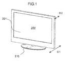
- Fig. 1 is a perspective view of a flat display unit.
- the flat display unit 200 includes a display portion 201 and a stand mechanism 215.
- the display portion 201 may be, for example, a liquid crystal display, a plasma display, an organic EL display, or the like.
- the stand mechanism 215 is mounted to a lower portion of the display portion 201, so that the display portion 201 can stand upright.
- a depth D1 of the stand mechanism 215 needs to be relatively large, and is larger than a depth D2 of the display portion 201.
- a depth D2 of a display portion 201 is about 10 cm, while a depth D1 of a stand mechanism 215 is about 30 to 35 cm.
- the packing box needs to have a size larger than the depth D1 of the stand mechanism 215, which reduces transport efficiency and requires a large space for storage or the like.
- the display portion 201 and the stand mechanism 215 are packed with the stand mechanism 215 being removed from the display portion 201 as is conventional, thereby reducing a volume of a packing box and improving transport efficiency. A packing method will be described later.
- Figs. 2A to 2C show an assembling view of the flat display unit.
- Fig. 2A is an assembling view of the stand mechanism 215.
- Figs. 2B is an assembling view of the flat display unit 210
- Figs. 2C is an assembling view of the stand mechanism 215.
- the stand mechanism 215 includes a stand 208 in contact with a floor surface, and a display portion-holding member 213 which supports the display portion 201 from below to connect the display portion 201 and the stand 208.
- the display portion-holding member 213 and the stand 208 are fixedly held by a mounting screw 214.
- the display portion 201 is inserted from above into the display portion-holding member 213 of the stand mechanism 215 and mounted, and fixedly held by display portion-securing screws 216 as shown in Fig. 2C .
- Figs. 3A to 3C illustrate the packing structure for packing the flat display unit.
- Fig. 3A is a perspective view showing an appearance of the packing structure of the flat display unit.
- Fig. 3B is a perspective view showing an inside of a packing box.
- Fig. 3C is a perspective exploded view showing the entire packing structure.
- the packing box includes an upper part 202 and a lower part 203.
- the upper part 202 and the lower part 203 have an upper connection hole 209 and a lower connection hole 211, respectively. Positions of the upper connection hole 209 and the lower connection hole 211 in the upper part 202 and the lower part 203 are set so that the upper connection hole 209 is aligned with the lower connection hole 211 when the upper part 202 is placed over and assembled to the lower part 203.
- the upper part 202 is placed over the lower part 203 to align the upper connection hole 209 with the lower connection hole 211, and a resin connecting member 207 is inserted into the upper connection hole 209 and the lower connection hole 211 with a protrusion being oriented inward of the packing box to connect the upper part 202 and the lower part 203.
- the connecting member 207 has an opening oriented outward of the packing box and into which a hand can be inserted.
- the connecting member 207 also serves as a grip in holding the packing box, and the hand is placed on the connecting member 207 when the packing box is lifted.
- the display portion 201 is covered with a protective inner bag 210 such as a polyethylene film so as to prevent damage to a screen or a casing of the display portion 201.
- the display portion 201 covered with the inner bag 210 is placed in the packing box 203, and held by a cushioning material.
- an upper cushioning member 204 and a lower cushioning material 205 formed of foamed styrol or the like are used as cushioning materials.
- two upper cushioning members 204 and two lower cushioning material 205 are placed in positions corresponding to four corners of the display portion 201 in the packing box 203.
- the two upper cushioning members 204 are placed on a side of the upper part 202, and hold upper left and right ends of the display portion 201 from above, respectively.
- the two lower cushioning members 205 are placed on a bottom surface of the lower part 203, and support lower left and right ends of the display portion 201 from below, respectively.
- the upper cushioning members 204 and the lower cushioning material 205 are provided between the display portion 201 and the upper and lower parts 202 and 203, and thus absorb vibration, impact, or the like from outside and prevent the vibration, the impact, or the like from being transferred to the display portion 201, thereby preventing damage to the display portion 201.
- the stand mechanism 215 and the display portion 201 are packed without the stand mechanism 215 being mounted to the display portion 201.
- the stand mechanism 215 is packed in a rear portion of the display portion 201 using a stand cushioning material 206.
- bending portions 212 which can be bent inward of the packing box are provided on a front side (back side of a sheet surface) of left and right side surfaces so that the front side bending portions 212 in a bent state can abut against the lower cushioning material 205. This prevents the lower cushioning material 205 from being lifted together with the display portion 201 when the display portion 201 is lifted and drawn from the lower part 203. Details of the front side bending portion 212 will be described later.
- Figs. 4A to 4D illustrate unpacking of the packing structure according to this embodiment.
- an upper portion of the upper part 202 is opened, and the upper cushioning material 204 is taken out of the upper part 202.
- the connecting member 207 (grip) connecting the upper part 202 and the lower part 203 is removed, and as shown in Fig. 4B , the upper part 202 is lifted upward and removed from the lower part 203.
- the stand cushioning material 206, the display portion-holding member 213, and the stand 208 are taken out of the lower part 203. Only the stand 208 is herein shown for simplicity.
- the display portion-holding member 213 and the stand 208 are assembled as in Fig. 2A to form the stand mechanism 215.
- a bending portion 212 on a rear side is removed.
- the lower part 203 is developed firstly as indicated by an arrow a, and secondly as indicated by arrow b.
- the inner bag 210 protecting the display portion 201 is pushed down to the lower cushioning material 205, and hands are inserted from inside the inner bag 210 into manual insertion portions or gaps 217 (see Fig. 4C ) formed in the lower cushioning material 205 to grip left and right ends of the display portion 201.
- the display portion 201 is lifted and assembled to the stand mechanism 215 having assembled before by a method shown in Figs. 2B and 2C .
- the lower cushioning material 205 includes the manual insertion portions 217 so that hands can be inserted into the lower left and right ends of the display portion 201 to allow the hands to be inserted into the lower left and right ends of the display portion 201.
- the hands are inserted into the lower left and right ends, and thus a lifting person can hold the lower side of the display portion 201 at a portion close to the person's body.
- a large display portion 201 can be easily taken out of the lower part 203.
- the screen of the display portion 201 may be damaged.
- the manual insertion portions 217 are provided in the lower cushioning material 205 on the rear side of the display portion 201. This allows the display portion 201 to be lifted so that the screen (front surface) of the display portion 201 is not touched as much as possible.
- the display portion 201 when the display portion 201 is inserted into the stand mechanism 215 during installation, it is necessary to confirm from the rear side of the display portion 201 that the display portion 201 is inserted into the stand mechanism 215 so as to prevent improper insertion or prevent the stand mechanism 215 from being accidentally brought into contact with and damaging the display portion 201.
- the manual insertion portions 217 are provided on the rear side of the lower cushioning material 205 as described above, and thus the hands gripping the display portion 201 from the rear side can be placed on the lower side.
- a right person in Fig. 4D grips a lower right end of the display portion 201 from the rear side of the display portion 201 by the left hand and an upper right end of the display portion 201 by the right hand.
- the hand (right hand) gripping the display portion 201 from the rear side is placed on the lower of the display portion 201, and thus the right person naturally the rear side of the display portion 201 when lifting the display portion 201, and the right person can lift the display portion 201 while looking at the rear side of the display portion 201.
- the hand (right hand of the right person) gripping the display portion 201 from the rear side is placed on the upper side, the hand holding the upper side gets in the way to make it difficult to confirm a portion to be inserted into the stand mechanism 215 on the rear side.
- the manual insertion portions 217 are provided on the rear side of the lower cushioning material 205 to make it easy to confirm the rear side of the display portion 201 when lifting the display portion 201, thereby improving workability in insertion into the stand mechanism 215.
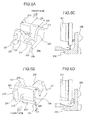
- Figs. 5A to 5D show a specific example of the lower cushioning material 205 which is a feature of this embodiment.
- the lower cushioning material 205 in this embodiment has, as shown in Fig. 5A and 5B , a front rib A218 and a front rib B219 protruding on the front side at the left and right ends on the front side (back side of the sheet surface), and a rear rib A221 and a rear rib B222 protruding on the rear side at the left and right ends on the rear side (front side of the sheet surface).
- the front rib A218 and the front rib B219 abut against an inner surface on the front side of the lower part 203
- the rear rib A221 and the rear rib B222 abut against an inner surface on the rear side of the lower part 203.
- the ribs have a function of reducing the impact from the front side and the rear side on surfaces in contact with the lower part 203, and protecting the display portion 201.
- the front rib A218 and the front rib B219, and the rear rib A221 and the rear rib B222 are provided on areas other than a region (width D4 in Fig. 5A ) in which the manual insertion portion 217 described later is provided (or provided to slightly overlap the region). This can prevent a load to each rib from being mainly transferred to a portion formed with the manual insertion portion 217.
- the lower cushioning material 205 has the manual insertion portion 217 which is a gap having such a size that a user can insert the hand therein.
- the gap that is, the manual insertion portion 217 is provided under each of the lower left and right ends of the display portion 201 in packing.
- the manual insertion portion 217 has a width D4 of about 10 to about 11 cm, which is a horizontal (lateral) size when viewed from the front surface or the rear surface.
- a gap D5 which is a distance between the lower end of the display portion 201 and the bottom surface of the manual insertion portion 217 of the lower cushioning material 205 is preferably about 3 to about 4 cm.
- fingers also need to be inserted between the front surface of the display portion 201 and the surface of the lower cushioning material 205 facing the front surface of the display portion 201, and thus a gap D6 between the front surface of the display portion 201 and the surface of the lower cushioning material 205 facing the front surface of the display portion 201 is preferably about 1.5 to about 3 cm.
- the hand can be easily inserted from the lower end of the display portion 201 to grip the lower end of the display portion 201, and the display portion 201 can be safely gripped and taken out.
- the manual insertion portion 217 needs to have such a size that a human's hand can be inserted therein, and thus a relatively large gap (space) for insertion of the hand is required relative to the size of the lower cushioning material 205.
- a relatively large gap (space) for insertion of the hand is required relative to the size of the lower cushioning material 205.
- the display portion 201 it is necessary that the hand can be inserted from the rear side to the front side of the lower portion of the display portion 201. This reduces a thickness on the front side of the lower cushioning material 205 and reduces mechanical strength of the portion.
- the lower cushioning material 205 may be cracked or damaged when vibration, impact, or the like is applied thereto from outside, which prevents the packed display portion 201 from being reliably protected. If the lower cushioning material 205 is damaged, the lower cushioning material 205 cannot be reused.
- a reinforcing front rib C220 protruding on the front side is provided between the front rib A218 and the front rib B219 on the front side of the lower cushioning material 205.
- This increases strength on the front side of the lower cushioning material 205.
- a gap D3 in a depth direction is provided between a tip of the front rib C220 and tips of the front rib A218 and the front rib B219.
- a protrusion size of the front rib C220 on the front side is smaller than those of the front rib A218 and the front rib B219 so that the front rib C220 is not brought into contact with the inner surface of the lower part 203.
- the front rib A218 and the front rib B219 each has a fan shape with a width increasing from the front side toward the rear side when the lower cushioning material 205 is viewed from above so as to easily absorb the impact.
- the front rib C220 not in contact with the lower part 203 is not directly subjected to the impact, thereby preventing the front rib C220 from being broken by the impact from the front surface.
- the rear rib A221 and the rear rib B222 each also has a fan shape with a width increasing from the rear side toward the front surface when the lower cushioning member 205 is viewed from above.
- crack preventing structures A224 and B225 are provided in the front rib A218 and the front rib B219, and the rear rib A221 and the rear rib B222.
- the crack preventing structure A224 and the crack preventing structure B225 are formed by cutting or rounding a corner portion of each rib corresponding to each corner portion of the packing box.
- the crack preventing structures A224 and B225 are provided to eliminate a portion in contact with the corner portion of the lower part 203.
- the impact on the front rib A218 and the front rib B219, and the rear rib A221 and the rear rib B222 is reduced to prevent the front rib A218 and the front rib B219, and the rear rib A221 and the rear rib B222 front being broken by the impact.
- a recessed space surrounded by the front rib A218, the front rib B219, and the reinforcing front rib C220 is a placement space 228.
- the space is used as an insertion space of the connecting member 207, or various interior parts of the display unit (for example, a cable or a remote control) can be placed in the space.
- a sloping rear tapered portion 226 is provided on the rear side of the lower cushioning material 205 and on a middle side of the packing box of the manual insertion portion 217 so that the hand can be easily inserted between the inner bag 210 and the display portion 201.
- the rear tapered portion 226 is provided in the lower cushioning material 205, and thus the hand can be easily inserted when the inner bag 210 is pushed down, thereby improving workability.
- a sloping side tapered portion 227 is provided on a lateral side of the lower cushioning material 205 (side wall of the lower cushioning material 205 adjacent to the manual insertion portion 217) so that the workers can easily grip the lower left and right ends of the display portion 201 with the hands being inserted from the lateral sides.
- the side tapered portion 227 is provided to allow the workers to easily grip the display portion 210 from the lateral side, thereby improving workability.
- a recess 223 is provided on the front side of the lower cushioning material 205 and at the corner portion in contact with the corner portion of the lower part 203, and abuts against the front side bending portion 212 as described above to prevent the lower cushioning material 205 from being lifted together with the display portion 201 when the display portion 201 is lifted and drawn from the lower part 203. Details thereof will be described later.
- Fig. 5 only the right lower cushioning material 205 which supports the lower right end of the display portion 201 from below is shown, but it goes without saying that the left lower cushioning material 205 has a structure symmetrical to the right lower cushioning material 205.
- the packing box has the structure in which the upper part 202 the lower part 203 are connected by the connecting member 207, but may have a packing structure in which the upper part 202 and the lower part 203 are integrated without the connecting member 207.
- the stand mechanism 215 is packed with the stand mechanism 215 being separated into the display portion-holding member 213 and the stand 208, but the stand mechanism 215 may be packed with the display portion-holding member 213 and the stand 208 being previously assembled as the stand mechanism 215.
- the upper cushioning material 204 and the lower cushioning material 205 are formed of laterally separated parts, but the upper and lower cushioning materials each may be formed of a laterally integrated cushioning material.
- Fig. 6 is a sectional view of a state where the lower cushioning material 205 is mounted to the lower part 203.
- the lower cushioning material 205 may be taken out together with the display portion 201 due to a friction force generated on the contact surface between the display portion 201 and the lower cushioning material 205 or if the lower cushioning material 205 is caught on the hand when the hand is inserted into the manual insertion portion 217 in the lower cushioning material 205 to take out the display portion 201.
- a taking-cut preventing structure is provided in the lower part 203 and the lower cushioning material 205.
- the taking-out preventing structure includes the front side bending portion 212 provided in the side surface of the lower part 203, and the recess 223 provided on the front side of the lower cushioning material 205 and at the corner portion in contact with the corner portion of the lower part 203.
- the front side bending portion 212 is placed in the space formed by the recess 223.
- the front side bending portion 212 abuts against and is caught on the recess 223, and a force is applied to the bending portion 212 in a direction opposite to a direction of taking out the display portion 201 (that is, downward).
- the lower cushioning material 205 is pressed down by the front side bending portion 212 to prevent the lower cushioning material 205 from being taken out together with the display portion 201.
- the front side bending portion 212 is preferably provided on the lateral side rather than the front side of the lower part 203.
- a bending portion (rear side bending portion 233) is also provided on a rear side of the side surface of the lower part 203, and has a function of a connecting portion for maintaining a box shape of the lower part 203 together with the front side bending portion 212.
- Such a function will be described with reference to Figs. 7A to 7B showing an assembling method of the lower part 203 of the packing box 202.
- a front portion 203a and a rear portion 203b of the lower part 203 are first bent inward perpendicularly to a bottom surface 203f of the lower part 203.
- inner wall side portions 203e and 203d connected to the front portion 203a and the rear portion 203b, respectively are bent inward perpendicularly to the front portion 203 a and the rear portion 203b, and then an outer wall side portion 203c is bent inward perpendicularly to the bottom surface 203f.
- the front side bending portion 212 and the rear side bending portion 233 are previously formed in the inner wall side portions 203e and 203d and the outer wall side portion 203c. Then, as shown in Fig. 7C , the front side bending portion 212 and the rear side bending portion 233, respectively are bent inward to engage the inner wall side portions 203e and 203d with the outer wall side portion 203c. This prevents the assembled lower part 203 from being accidentally developed, and allows the box shape to be maintained.
- the front side bending portion 212 and the rear side bending portion 233 have a function of an engaging portion of the lower part 203.
- the front side bending portion 212 has the function of the taking-cut preventing structure as described above and also the function of the engaging portion of the lower part 203.
- the lower part 203 has the manual insertion portion 217, thereby allowing the display portion 201 to be easily taken out, and preventing the lower cushioning material 205 from being taken out of the lower part 203 together with the display portion 201, thereby improving workability in taking out the display portion 201.
Landscapes
- Engineering & Computer Science (AREA)
- Mechanical Engineering (AREA)
- Multimedia (AREA)
- Signal Processing (AREA)
- Packaging Of Machine Parts And Wound Products (AREA)
- Buffer Packaging (AREA)
Abstract
Description
- The present invention relates to a package structure with a flat display unit packed therein which uses a liquid crystal display panel, a plasma display panel, or an organic EL display panel as an image display device, or a package structure for packing a flat display unit.
- Generally, a flat display unit such as a television receiver is packed in a packing box such as a corrugated box or a package including a cushioning member such as foamed styrol or the like (hereinafter sometimes referred to as "packing structure") and conveyed from a manufacturing plant to a dealer or a user. The packing structure has a function of reducing vibration, impact, or the like from outside in a transport process and protecting the flat display unit.
-
JP-A-2008-74416 JP-A-2009-262941 - In the packing structure described in
JP-A-2008-74416 JP-A-2009-262941 - For
JP-A-2008-74416 - For
JP-A-2009-262941 - The present invention is achieved in view of the above-described problems of the conventional techniques, and provides a package structure for packing a flat display unit having a technique suitable for improving workability in unpacking.
- The present invention has features described in Claims. Preferably, a lower cushioning material has a manual insertion portion so that a lifting person can hold a lower side of a flat display unit at a portion close to the person's body. To prevent separation or break due to a reduction in strength at that time, a reinforcing front rib is provided on a front side of the lower cushioning material. Also, to prevent the lower cushioning material from being caught on a hand and being taken out together with the flat display unit when the flat display unit is taken out, a packing structure is provided in which the lower cushioning material has a recess and a lower packing box has a bending portion.
- According to the present invention, the flat display unit can be easily taken out of the package, and workability in unpacking can be improved.
- Other objects, features and advantages of the invention will become apparent from the following description of the embodiments of the invention taken in conjunction with the accompanying drawings.
- The invention will now be described with reference to the drawing wherein:
-
Fig. 1 is a perspective view of a flat display unit, -
Fig. 2A is a perspective view showing assembling of the stand mechanism, -
Figs. 2B is a perspective view showing assembling of the flat display unit, -
Figs. 2C . is a perspective view showing assembling of the stand mechanism, -
Fig. 3A is a perspective view showing an appearance of the packing structure for packing the flat display unit, -
Fig. 3B is a perspective view showing an inside of a packing box, -
Fig. 3C is an exploded perspective view showing the entire packing structure, -
Figs. 4A is a perspective view showing unpacking of the packing structure according to an embodiment in which the an upper cushioning material is taken out of the upper part, -
Figs. 4B is a perspective view showing unpacking of the packing structure according to the embodiment in which the upper part is lifted upward and removed from the lower part, -
Figs. 4C is a perspective view showing unpacking of the packing structure according to the embodiment in which the lower part is developed, -
Figs. 4D is a perspective view showing unpacking of the packing structure according to the embodiment in which left and right ends of the display portion are gripped by inserting human hands into gaps, -
Fig. 5A is a rear perspective view showing an example of the lower cushioning material of the embodiment, -
Fig. 5B is a front perspective view showing an example of the lower cushioning material of the embodiment, -
Fig. 5C is a section view showing an example of the lower cushioning material of the embodiment, -
Fig. 5D is a section view showing an example of the lower cushioning material of the embodiment, -
Fig. 6 is a sectional view of the lower cushioning material mounted to the lower part, -
Fig. 7A is a perspective view showing a first step of assembling method of the lower part of the packing box, -
Fig. 7B is a perspective view showing a step of assembling method of the lower part of the packing box, -
Fig. 7C is a perspective view showing a third of assembling method of the lower part of the packing box, and -
Fig. 7D is a perspective view showing a front bending portion and the rear side bending portion of the lower part of the packing box. - Now, an embodiment of the present invention will be described with reference to the drawings. In the drawings, components having a common function are denoted by the same reference numerals, and overlapping descriptions will be omitted.
- First, a configuration of a flat display unit which is an object to be packed will be described.
-
Fig. 1 is a perspective view of a flat display unit. Theflat display unit 200 includes adisplay portion 201 and astand mechanism 215. Thedisplay portion 201 may be, for example, a liquid crystal display, a plasma display, an organic EL display, or the like. As shown inFig. 1 , thestand mechanism 215 is mounted to a lower portion of thedisplay portion 201, so that thedisplay portion 201 can stand upright. - To maintain the
display portion 201 in the standing state as shown inFig. 1 and prevent thedisplay portion 201 from easily falling down, a depth D1 of thestand mechanism 215 needs to be relatively large, and is larger than a depth D2 of thedisplay portion 201. For example, for a 50-inch flat display unit, a depth D2 of adisplay portion 201 is about 10 cm, while a depth D1 of astand mechanism 215 is about 30 to 35 cm. - When the
display portion 201 and thestand mechanism 215 mounted to thedisplay portion 201 are packed into the packing box and transported, the packing box needs to have a size larger than the depth D1 of thestand mechanism 215, which reduces transport efficiency and requires a large space for storage or the like. Thus, for a packing structure for the flat display unit according to the embodiment of the present invention, thedisplay portion 201 and thestand mechanism 215 are packed with thestand mechanism 215 being removed from thedisplay portion 201 as is conventional, thereby reducing a volume of a packing box and improving transport efficiency. A packing method will be described later. -
Figs. 2A to 2C show an assembling view of the flat display unit.Fig. 2A is an assembling view of thestand mechanism 215.Figs. 2B is an assembling view of theflat display unit 210, andFigs. 2C is an assembling view of thestand mechanism 215. As shown inFig. 2A , thestand mechanism 215 includes astand 208 in contact with a floor surface, and a display portion-holdingmember 213 which supports thedisplay portion 201 from below to connect thedisplay portion 201 and thestand 208. The display portion-holdingmember 213 and thestand 208 are fixedly held by a mountingscrew 214. As shown inFig. 2B , thedisplay portion 201 is inserted from above into the display portion-holdingmember 213 of thestand mechanism 215 and mounted, and fixedly held by display portion-securingscrews 216 as shown inFig. 2C . - Next, the packing structure for packing the flat display unit therein will be described in detail.
-
Figs. 3A to 3C illustrate the packing structure for packing the flat display unit.Fig. 3A is a perspective view showing an appearance of the packing structure of the flat display unit.Fig. 3B is a perspective view showing an inside of a packing box.Fig. 3C is a perspective exploded view showing the entire packing structure. - The packing box includes an
upper part 202 and alower part 203. Theupper part 202 and thelower part 203 have anupper connection hole 209 and alower connection hole 211, respectively. Positions of theupper connection hole 209 and thelower connection hole 211 in theupper part 202 and thelower part 203 are set so that theupper connection hole 209 is aligned with thelower connection hole 211 when theupper part 202 is placed over and assembled to thelower part 203. Then, theupper part 202 is placed over thelower part 203 to align theupper connection hole 209 with thelower connection hole 211, and aresin connecting member 207 is inserted into theupper connection hole 209 and thelower connection hole 211 with a protrusion being oriented inward of the packing box to connect theupper part 202 and thelower part 203. Further, the connectingmember 207 has an opening oriented outward of the packing box and into which a hand can be inserted. Specifically, the connectingmember 207 also serves as a grip in holding the packing box, and the hand is placed on the connectingmember 207 when the packing box is lifted. - The
display portion 201 is covered with a protectiveinner bag 210 such as a polyethylene film so as to prevent damage to a screen or a casing of thedisplay portion 201. Thedisplay portion 201 covered with theinner bag 210 is placed in thepacking box 203, and held by a cushioning material. In this embodiment, anupper cushioning member 204 and alower cushioning material 205 formed of foamed styrol or the like are used as cushioning materials. As shown, twoupper cushioning members 204 and twolower cushioning material 205 are placed in positions corresponding to four corners of thedisplay portion 201 in thepacking box 203. The twoupper cushioning members 204 are placed on a side of theupper part 202, and hold upper left and right ends of thedisplay portion 201 from above, respectively. Meanwhile, the twolower cushioning members 205 are placed on a bottom surface of thelower part 203, and support lower left and right ends of thedisplay portion 201 from below, respectively. As such, theupper cushioning members 204 and thelower cushioning material 205 are provided between thedisplay portion 201 and the upper andlower parts display portion 201, thereby preventing damage to thedisplay portion 201. - As described above, to reduce a volume of the packing box, the
stand mechanism 215 and thedisplay portion 201 are packed without thestand mechanism 215 being mounted to thedisplay portion 201. As shown inFig. 3B or 3C , with thestand mechanism 215 being separated into thestand 208 and the display portion-holdingmember 213, thestand mechanism 215 is packed in a rear portion of thedisplay portion 201 using astand cushioning material 206. In thelower part 203, bendingportions 212 which can be bent inward of the packing box are provided on a front side (back side of a sheet surface) of left and right side surfaces so that the frontside bending portions 212 in a bent state can abut against thelower cushioning material 205. This prevents thelower cushioning material 205 from being lifted together with thedisplay portion 201 when thedisplay portion 201 is lifted and drawn from thelower part 203. Details of the frontside bending portion 212 will be described later. -
Figs. 4A to 4D illustrate unpacking of the packing structure according to this embodiment. As shown inFig. 4A , an upper portion of theupper part 202 is opened, and theupper cushioning material 204 is taken out of theupper part 202. Then, the connecting member 207 (grip) connecting theupper part 202 and thelower part 203 is removed, and as shown inFig. 4B , theupper part 202 is lifted upward and removed from thelower part 203. After theupper part 202 is removed, thestand cushioning material 206, the display portion-holdingmember 213, and thestand 208 are taken out of thelower part 203. Only thestand 208 is herein shown for simplicity. Then, the display portion-holdingmember 213 and thestand 208 are assembled as inFig. 2A to form thestand mechanism 215. - Next, as shown in
Fig. 4C , a bendingportion 212 on a rear side is removed. Then, thelower part 203 is developed firstly as indicated by an arrow a, and secondly as indicated by arrow b. As shown inFig. 4D , theinner bag 210 protecting thedisplay portion 201 is pushed down to thelower cushioning material 205, and hands are inserted from inside theinner bag 210 into manual insertion portions or gaps 217 (seeFig. 4C ) formed in thelower cushioning material 205 to grip left and right ends of thedisplay portion 201. Then, thedisplay portion 201 is lifted and assembled to thestand mechanism 215 having assembled before by a method shown inFigs. 2B and 2C . - As described above, in the packing structure according to this embodiment, the
lower cushioning material 205 includes themanual insertion portions 217 so that hands can be inserted into the lower left and right ends of thedisplay portion 201 to allow the hands to be inserted into the lower left and right ends of thedisplay portion 201. The hands are inserted into the lower left and right ends, and thus a lifting person can hold the lower side of thedisplay portion 201 at a portion close to the person's body. Thus, even alarge display portion 201 can be easily taken out of thelower part 203. - If the lower left and right ends of the
display portion 201 are gripped from the front side, the screen of thedisplay portion 201 may be damaged. Thus, themanual insertion portions 217 are provided in thelower cushioning material 205 on the rear side of thedisplay portion 201. This allows thedisplay portion 201 to be lifted so that the screen (front surface) of thedisplay portion 201 is not touched as much as possible. - Further, when the
display portion 201 is inserted into thestand mechanism 215 during installation, it is necessary to confirm from the rear side of thedisplay portion 201 that thedisplay portion 201 is inserted into thestand mechanism 215 so as to prevent improper insertion or prevent thestand mechanism 215 from being accidentally brought into contact with and damaging thedisplay portion 201. - Thus, in this embodiment, the
manual insertion portions 217 are provided on the rear side of thelower cushioning material 205 as described above, and thus the hands gripping thedisplay portion 201 from the rear side can be placed on the lower side. For example, as shown, a right person inFig. 4D grips a lower right end of thedisplay portion 201 from the rear side of thedisplay portion 201 by the left hand and an upper right end of thedisplay portion 201 by the right hand. Specifically, for the right person, the hand (right hand) gripping thedisplay portion 201 from the rear side is placed on the lower of thedisplay portion 201, and thus the right person naturally the rear side of thedisplay portion 201 when lifting thedisplay portion 201, and the right person can lift thedisplay portion 201 while looking at the rear side of thedisplay portion 201. The same applies to the left person. On the contrary, when the hand (right hand of the right person) gripping thedisplay portion 201 from the rear side is placed on the upper side, the hand holding the upper side gets in the way to make it difficult to confirm a portion to be inserted into thestand mechanism 215 on the rear side. - As such, in this embodiment, the
manual insertion portions 217 are provided on the rear side of thelower cushioning material 205 to make it easy to confirm the rear side of thedisplay portion 201 when lifting thedisplay portion 201, thereby improving workability in insertion into thestand mechanism 215. -
Figs. 5A to 5D show a specific example of thelower cushioning material 205 which is a feature of this embodiment. - When the
display portion 201 in a packed state falls down or is subjected to vibration or the like from outside, thedisplay portion 201 is subjected to an impact from the front side or the rear side. To reduce such an impact, thelower cushioning material 205 in this embodiment has, as shown inFig. 5A and 5B , a front rib A218 and a front rib B219 protruding on the front side at the left and right ends on the front side (back side of the sheet surface), and a rear rib A221 and a rear rib B222 protruding on the rear side at the left and right ends on the rear side (front side of the sheet surface). When the ribs are housed in the packing box, the front rib A218 and the front rib B219 abut against an inner surface on the front side of thelower part 203, and the rear rib A221 and the rear rib B222 abut against an inner surface on the rear side of thelower part 203. The ribs have a function of reducing the impact from the front side and the rear side on surfaces in contact with thelower part 203, and protecting thedisplay portion 201. The front rib A218 and the front rib B219, and the rear rib A221 and the rear rib B222 are provided on areas other than a region (width D4 inFig. 5A ) in which themanual insertion portion 217 described later is provided (or provided to slightly overlap the region). This can prevent a load to each rib from being mainly transferred to a portion formed with themanual insertion portion 217. - As described above, the
lower cushioning material 205 has themanual insertion portion 217 which is a gap having such a size that a user can insert the hand therein. The gap, that is, themanual insertion portion 217 is provided under each of the lower left and right ends of thedisplay portion 201 in packing. As shown inFig. 5A , to safely grip thedisplay portion 201, themanual insertion portion 217 has a width D4 of about 10 to about 11 cm, which is a horizontal (lateral) size when viewed from the front surface or the rear surface. As shown in a lateral sectional view of thelower cushioning material 205 inFig. 5C , with thedisplay portion 201 being placed on thelower cushioning material 205, a gap D5 which is a distance between the lower end of thedisplay portion 201 and the bottom surface of themanual insertion portion 217 of thelower cushioning material 205 is preferably about 3 to about 4 cm. As shown inFig. 5C and 5D , fingers also need to be inserted between the front surface of thedisplay portion 201 and the surface of thelower cushioning material 205 facing the front surface of thedisplay portion 201, and thus a gap D6 between the front surface of thedisplay portion 201 and the surface of thelower cushioning material 205 facing the front surface of thedisplay portion 201 is preferably about 1.5 to about 3 cm. Thus, as shown inFig. 5D , the hand can be easily inserted from the lower end of thedisplay portion 201 to grip the lower end of thedisplay portion 201, and thedisplay portion 201 can be safely gripped and taken out. - The
manual insertion portion 217, as described above, needs to have such a size that a human's hand can be inserted therein, and thus a relatively large gap (space) for insertion of the hand is required relative to the size of thelower cushioning material 205. In particular, for thedisplay portion 201 to be reliably held by the hand, as shown inFig. 5D , it is necessary that the hand can be inserted from the rear side to the front side of the lower portion of thedisplay portion 201. This reduces a thickness on the front side of thelower cushioning material 205 and reduces mechanical strength of the portion. If the strength of thelower cushioning material 205 is reduced, thelower cushioning material 205 may be cracked or damaged when vibration, impact, or the like is applied thereto from outside, which prevents the packeddisplay portion 201 from being reliably protected. If thelower cushioning material 205 is damaged, thelower cushioning material 205 cannot be reused. - To prevent such a crack or damage, a reinforcing front rib C220 protruding on the front side is provided between the front rib A218 and the front rib B219 on the front side of the
lower cushioning material 205. This increases strength on the front side of thelower cushioning material 205. Thus, even if themanual insertion portion 217 is provided to reduce the thickness of thelower cushioning material 205, a crack in or damage to thelower cushioning material 205 can be prevented to reliably protect the packeddisplay portion 201. Also, preventing the crack in or the damage to thelower cushioning material 205 allows thelower cushioning material 205 to be reused. - If the front rib C220 is directly subjected to an impact from the front surface, the front rib C220 may be broken to reduce the strength of the
lower cushioning material 205. Thus, in this embodiment, a gap D3 in a depth direction is provided between a tip of the front rib C220 and tips of the front rib A218 and the front rib B219. Specifically, when thelower cushioning material 205 is viewed from above, a protrusion size of the front rib C220 on the front side is smaller than those of the front rib A218 and the front rib B219 so that the front rib C220 is not brought into contact with the inner surface of thelower part 203. - With such a configuration, when an impact is applied from the front surface, a force by the impact is mainly applied to the front rib A218 and the front rib B219 in contact with the inner surface of the
lower part 203. The front rib A218 and the front rib B219 each has a fan shape with a width increasing from the front side toward the rear side when thelower cushioning material 205 is viewed from above so as to easily absorb the impact. Thus, the front rib C220 not in contact with thelower part 203 is not directly subjected to the impact, thereby preventing the front rib C220 from being broken by the impact from the front surface. The rear rib A221 and the rear rib B222 each also has a fan shape with a width increasing from the rear side toward the front surface when thelower cushioning member 205 is viewed from above. - When the packing box packing the
display portion 201 falls down from a corner and an impact is applied from outside, tip corner portions of the front rib A218 and the front rib B219, and the rear rib A221 and the rear rib B222 in contact with thelower part 203 are subjected to the impact, and the ribs may be broken. To prevent this, crack preventing structures A224 and B225 are provided in the front rib A218 and the front rib B219, and the rear rib A221 and the rear rib B222. The crack preventing structure A224 and the crack preventing structure B225 are formed by cutting or rounding a corner portion of each rib corresponding to each corner portion of the packing box. Thus, the crack preventing structures A224 and B225 are provided to eliminate a portion in contact with the corner portion of thelower part 203. Thus, even if the packing box packing thedisplay portion 210 falls down from the corner, the impact on the front rib A218 and the front rib B219, and the rear rib A221 and the rear rib B222 is reduced to prevent the front rib A218 and the front rib B219, and the rear rib A221 and the rear rib B222 front being broken by the impact. A recessed space surrounded by the front rib A218, the front rib B219, and the reinforcing front rib C220 is aplacement space 228. The space is used as an insertion space of the connectingmember 207, or various interior parts of the display unit (for example, a cable or a remote control) can be placed in the space. - As described above, when the user inserts the hand in the
manual insertion portion 217, it is necessary to first push down theinner bag 210 covering thedisplay portion 201 and place the hand between theinner bag 210 and thedisplay portion 201. A sloping reartapered portion 226 is provided on the rear side of thelower cushioning material 205 and on a middle side of the packing box of themanual insertion portion 217 so that the hand can be easily inserted between theinner bag 210 and thedisplay portion 201. The rear taperedportion 226 is provided in thelower cushioning material 205, and thus the hand can be easily inserted when theinner bag 210 is pushed down, thereby improving workability. Also, a sloping side taperedportion 227 is provided on a lateral side of the lower cushioning material 205 (side wall of thelower cushioning material 205 adjacent to the manual insertion portion 217) so that the workers can easily grip the lower left and right ends of thedisplay portion 201 with the hands being inserted from the lateral sides. The side taperedportion 227 is provided to allow the workers to easily grip thedisplay portion 210 from the lateral side, thereby improving workability. - As shown in
Fig. 5 , arecess 223 is provided on the front side of thelower cushioning material 205 and at the corner portion in contact with the corner portion of thelower part 203, and abuts against the frontside bending portion 212 as described above to prevent thelower cushioning material 205 from being lifted together with thedisplay portion 201 when thedisplay portion 201 is lifted and drawn from thelower part 203. Details thereof will be described later. - In
Fig. 5 , only the rightlower cushioning material 205 which supports the lower right end of thedisplay portion 201 from below is shown, but it goes without saying that the leftlower cushioning material 205 has a structure symmetrical to the rightlower cushioning material 205. - In this embodiment, the packing box has the structure in which the
upper part 202 thelower part 203 are connected by the connectingmember 207, but may have a packing structure in which theupper part 202 and thelower part 203 are integrated without the connectingmember 207. Also in this embodiment, thestand mechanism 215 is packed with thestand mechanism 215 being separated into the display portion-holdingmember 213 and thestand 208, but thestand mechanism 215 may be packed with the display portion-holdingmember 213 and thestand 208 being previously assembled as thestand mechanism 215. Further in this embodiment, theupper cushioning material 204 and thelower cushioning material 205 are formed of laterally separated parts, but the upper and lower cushioning materials each may be formed of a laterally integrated cushioning material. - Next, the front
side bending portion 212 will be described.Fig. 6 is a sectional view of a state where thelower cushioning material 205 is mounted to thelower part 203. When thedisplay portion 201 is taken out of thelower part 203, thelower cushioning material 205 may be taken out together with thedisplay portion 201 due to a friction force generated on the contact surface between thedisplay portion 201 and thelower cushioning material 205 or if thelower cushioning material 205 is caught on the hand when the hand is inserted into themanual insertion portion 217 in thelower cushioning material 205 to take out thedisplay portion 201. To prevent this, in this embodiment, as shown inFig. 6 , a taking-cut preventing structure is provided in thelower part 203 and thelower cushioning material 205. The taking-out preventing structure includes the frontside bending portion 212 provided in the side surface of thelower part 203, and therecess 223 provided on the front side of thelower cushioning material 205 and at the corner portion in contact with the corner portion of thelower part 203. When bent inward of the packing box, the frontside bending portion 212 is placed in the space formed by therecess 223. - For such a taking-cut preventing structure, if the
display portion 201 is about to be taken out of thelower part 203, the frontside bending portion 212 abuts against and is caught on therecess 223, and a force is applied to the bendingportion 212 in a direction opposite to a direction of taking out the display portion 201 (that is, downward). Thus, when thedisplay portion 201 is taken out, thelower cushioning material 205 is pressed down by the frontside bending portion 212 to prevent thelower cushioning material 205 from being taken out together with thedisplay portion 201. When thedisplay portion 201 is taken out while being rotated, a friction force generated between thedisplay portion 201 and thelower cushioning material 205 is larger in regions on the lateral sides than on the front side or the rear side. Thus, the frontside bending portion 212 is preferably provided on the lateral side rather than the front side of thelower part 203. - A bending portion (rear side bending portion 233) is also provided on a rear side of the side surface of the
lower part 203, and has a function of a connecting portion for maintaining a box shape of thelower part 203 together with the frontside bending portion 212. Such a function will be described with reference toFigs. 7A to 7B showing an assembling method of thelower part 203 of thepacking box 202. - When the
lower part 203 is assembled in packing, as shown inFig. 7A , afront portion 203a and arear portion 203b of thelower part 203 are first bent inward perpendicularly to abottom surface 203f of thelower part 203. Then, as shown inFig. 7B , innerwall side portions front portion 203a and therear portion 203b, respectively are bent inward perpendicularly to thefront portion 203 a and therear portion 203b, and then an outerwall side portion 203c is bent inward perpendicularly to thebottom surface 203f. The frontside bending portion 212 and the rearside bending portion 233, respectively are previously formed in the innerwall side portions wall side portion 203c. Then, as shown inFig. 7C , the frontside bending portion 212 and the rearside bending portion 233, respectively are bent inward to engage the innerwall side portions wall side portion 203c. This prevents the assembledlower part 203 from being accidentally developed, and allows the box shape to be maintained. As such, in this embodiment, the frontside bending portion 212 and the rearside bending portion 233 have a function of an engaging portion of thelower part 203. Specifically, the frontside bending portion 212 has the function of the taking-cut preventing structure as described above and also the function of the engaging portion of thelower part 203. - As described above, with the package (packing structure) of the flat display unit according to this embodiment, the
lower part 203 has themanual insertion portion 217, thereby allowing thedisplay portion 201 to be easily taken out, and preventing thelower cushioning material 205 from being taken out of thelower part 203 together with thedisplay portion 201, thereby improving workability in taking out thedisplay portion 201. - It should be further understood by those skilled in the art that although the foregoing description has been made on embodiments of the invention, the invention is not limited thereto and various changes and modifications may be made without departing from the spirit of the invention and the scope of the appended claims.
Claims (14)
- A package structure with a flat display unit (200) packed therein comprising a packing box (202, 203) and a cushioning material (205) which is placed on a bottom side of the packing box (203) and supports lower left and right ends of the flat display unit (200) packed in the packing box (202, 203) from below,
characterized in that gaps (217) are formed in portions of the cushioning material (205)corresponding to the lower left and right ends of the flat display unit (200). - The package structure with a flat display unit (200) packed therein according to claim 1, characterized in that each of the gaps (217) formed in the cushioning material (205) has such a size that a human's hand can be inserted into the gap.
- The package structure with a flat display unit (200) packed therein according to claim 1 or 2, characterized in that the gap is provided on a rear side of the cushioning material.
- The package structure with a flat display unit (200) packed therein according to claim 3, characterized in that the gap has a width of 10 to 11 cm when the cushioning material (205) is viewed from the rear side, and a distance between a lower end of the flat display unit (200) and a bottom surface of the gap is, when the cushioning material (205) is viewed from a lateral side, 3 to 4 cm with the flat display unit (200) being placed on the cushioning material (205).
- The package structure with a flat display unit (200) packed therein according to claim 4, characterized in that with the flat display unit (200) being placed on the cushioning material (205), a distance between a front surface of the flat display unit (200) and a surface of the gap facing the front surface of the flat display unit (200) when the cushioning material (205) is viewed from the lateral side is 1.5 to 3 cm.
- The package structure with a flat display unit (200) packed therein according to claim 4, characterized in that a pair of first ribs (218, 219) which abut against an inner surface on the front side of the package are provided at left and right ends on the front side of the cushioning material (205), and a pair of second ribs (221, 222) which abut against an inner surface on the rear side of the package are provided at left and right ends on the rear side of the cushioning material (205).
- The package structure with a flat display unit (200) packed therein according to claim 6, characterized in that the first rib (218, 219) and the second rib (221, 222) are provided on areas other than regions in which the gaps are provided.
- The package structure with a flat display unit (200) packed therein according to claim 6, characterized in that the first rib (218, 219) has a fan shape with a width increasing from the front side toward the rear side when the cushioning material (205) is viewed from above, and the second rib (221, 222) has a fan shape with a width increasing from the rear side toward the front side when the cushioning material (205) is viewed from above.
- The package structure with a flat display unit (200) packed therein according to claim 6, characterized in that a reinforcing rib (220) having a smaller size, when the cushioning material (205) is viewed from above, than the first rib (218, 219) is provided between the pair of first ribs (218, 219).
- The package structure with a flat display unit (200) packed therein according to claim 6, characterized in that corner portions of the first and second ribs (218, 219, 221, 222) corresponding to corner portions of the packing box (203) are cut or rounded.
- The package structure with a flat display unit (200) packed therein according to claim 6, characterized in that lower corner portions of the first and second ribs (218, 219, 221, 220) are configured so as not to be brought into contact with the corner portions of the packing box (203).
- The package structure with a flat display unit (200) packed therein according to claim 2, characterized in that a first taper (227) is provided in a side wall adjacent to the gap of the cushioning material (205).
- The package structure with a flat display unit (200) packed therein according to claim 12, characterized in that a second taper (226) is provided on a middle side of the packing box of the gap of the cushioning material (205).
- The package structure with a flat display unit (200) packed therein according to claim 2, characterized in that a bending portion (212, 233) which can be bent inward of the packing box (203) is provided in a side surface (203c, 203d, 203e) of the packing box (203), a recess (223) in which the bent bending portion (212, 233) is placed is further provided at the corner portion on the front side of the cushioning material (205) so that the recess (223) is caught on the bending portion (212, 233) when the cushioning material (205) is drawn upward from the packing box (203).
Applications Claiming Priority (1)
| Application Number | Priority Date | Filing Date | Title |
|---|---|---|---|
| JP2010041284A JP5550381B2 (en) | 2010-02-26 | 2010-02-26 | Package containing flat display device and package of flat display device |
Publications (2)
| Publication Number | Publication Date |
|---|---|
| EP2361838A1 true EP2361838A1 (en) | 2011-08-31 |
| EP2361838B1 EP2361838B1 (en) | 2013-08-14 |
Family
ID=43983785
Family Applications (1)
| Application Number | Title | Priority Date | Filing Date |
|---|---|---|---|
| EP10189502.7A Active EP2361838B1 (en) | 2010-02-26 | 2010-10-29 | Package structure with a flat display unit packed therein and package structure for packing a flat display unit |
Country Status (4)
| Country | Link |
|---|---|
| US (1) | US8499934B2 (en) |
| EP (1) | EP2361838B1 (en) |
| JP (1) | JP5550381B2 (en) |
| CN (1) | CN102167192B (en) |
Cited By (2)
| Publication number | Priority date | Publication date | Assignee | Title |
|---|---|---|---|---|
| EP2586725A1 (en) * | 2011-10-25 | 2013-05-01 | Funai Electric Co., Ltd. | Display device packaging structure, television set, and display device assembly method |
| EP3845794A1 (en) * | 2019-12-30 | 2021-07-07 | Samsung Electronics Co., Ltd. | Display apparatus and assembly method thereof |
Families Citing this family (12)
| Publication number | Priority date | Publication date | Assignee | Title |
|---|---|---|---|---|
| JP5153956B1 (en) * | 2011-12-26 | 2013-02-27 | シャープ株式会社 | Packaging structure of display device |
| WO2013108604A1 (en) * | 2012-01-17 | 2013-07-25 | パナソニック株式会社 | Packaging device for flat panel displays |
| CN103863721A (en) * | 2012-12-12 | 2014-06-18 | 鸿富锦精密工业(深圳)有限公司 | Method for packaging and transferring televisions |
| US9446892B2 (en) * | 2014-04-09 | 2016-09-20 | Impact Salvage Enhancement Solutions | Protective enclosure for transporting an automobile door |
| CN106275694B (en) * | 2015-06-24 | 2020-05-08 | 鸿富锦精密工业(深圳)有限公司 | Packing case (food) |
| USD808799S1 (en) | 2015-11-17 | 2018-01-30 | Hunter Fan Company | Carton with color striping |
| CN107640440B (en) * | 2016-07-20 | 2019-09-06 | 佛山市顺德区美的电热电器制造有限公司 | Packaging liners and home appliance components for home appliances |
| CN107176380B (en) * | 2017-06-21 | 2019-09-17 | 深圳市华星光电技术有限公司 | Packing case |
| US20210061513A1 (en) * | 2019-09-04 | 2021-03-04 | Apple Inc. | Folding panel packaging with tab locks |
| KR102758867B1 (en) * | 2019-12-30 | 2025-01-24 | 삼성전자주식회사 | Dispay apparatus and method for assembling the same |
| CN111532543A (en) * | 2020-04-01 | 2020-08-14 | 海信视像科技股份有限公司 | Packing case (food) |
| CN113562307B (en) * | 2021-09-24 | 2021-12-10 | 苏州佳世达电通有限公司 | Display protection device |
Citations (3)
| Publication number | Priority date | Publication date | Assignee | Title |
|---|---|---|---|---|
| WO2007013319A1 (en) * | 2005-07-28 | 2007-02-01 | Matsushita Electric Industrial Co., Ltd. | Packaging box |
| EP1902962A2 (en) * | 2006-09-19 | 2008-03-26 | Funai Electric Co., Ltd. | Plasma television packing structure and panel display device packing structure |
| JP2009262941A (en) | 2008-04-23 | 2009-11-12 | Funai Electric Co Ltd | Packing structure of flat panel display |
Family Cites Families (24)
| Publication number | Priority date | Publication date | Assignee | Title |
|---|---|---|---|---|
| US3938661A (en) * | 1974-10-17 | 1976-02-17 | Republic Packaging Corporation | Packing brace |
| JPS60184867U (en) * | 1984-05-18 | 1985-12-07 | 旭化成株式会社 | Cushioning material for collective packaging |
| JP2577104B2 (en) | 1989-01-24 | 1997-01-29 | 東洋エンジニアリング株式会社 | Method and apparatus for producing multi-component powder fired material |
| JPH0544870U (en) * | 1991-11-11 | 1993-06-15 | 三菱電機株式会社 | Cardboard cushioning material for television receivers |
| JPH07242233A (en) | 1994-03-03 | 1995-09-19 | Mitsubishi Electric Corp | Packaging box with cushioning material |
| US5515976A (en) * | 1995-08-18 | 1996-05-14 | Plastofilm Industries, Inc. | Packaging for fragile articles within container |
| JPH0995361A (en) | 1995-09-29 | 1997-04-08 | Kanegafuchi Chem Ind Co Ltd | Buffer packaging method |
| US6367624B1 (en) * | 1998-10-14 | 2002-04-09 | Northrop Grumman Corporation | Optical component packaging |
| US6105765A (en) * | 1999-06-29 | 2000-08-22 | Chu; Cheng-Kang | Package case for electric appliances and computers |
| US6382422B1 (en) * | 2000-09-13 | 2002-05-07 | Hewlett-Packard Company | Packaging system for a family of products |
| US6467619B1 (en) * | 2000-09-25 | 2002-10-22 | Corey Leen | Multiple halogen lamp storage container |
| JP3709799B2 (en) * | 2001-03-14 | 2005-10-26 | ソニー株式会社 | Packing material for packaging |
| JP2002284148A (en) * | 2001-03-26 | 2002-10-03 | Sanyo Electric Co Ltd | Packaging box with cushioning material |
| JP2004182237A (en) * | 2002-11-29 | 2004-07-02 | Shinano Kenshi Co Ltd | Buffer material |
| JP3985268B2 (en) * | 2004-03-12 | 2007-10-03 | 船井電機株式会社 | Electronic equipment packaging box |
| JP2007008483A (en) * | 2005-06-28 | 2007-01-18 | Fujitsu General Ltd | Packing equipment |
| JP2007084142A (en) | 2005-09-26 | 2007-04-05 | Fujifilm Corp | Exterior box |
| JP2007308190A (en) * | 2006-05-22 | 2007-11-29 | Sharp Corp | Thin electronic device packaging structure and cushioning material used therefor |
| CN2928758Y (en) * | 2006-07-21 | 2007-08-01 | 厦门华侨电子股份有限公司 | Packaging structure of TV set |
| JP2008222257A (en) | 2007-03-12 | 2008-09-25 | Pioneer Electronic Corp | Packing material |
| JP2008222263A (en) * | 2007-03-12 | 2008-09-25 | Takahisa Watanabe | Packaging device |
| JP2009046138A (en) * | 2007-08-17 | 2009-03-05 | Funai Electric Co Ltd | Apparatus packing device |
| JP5084414B2 (en) * | 2007-09-12 | 2012-11-28 | 三菱電機株式会社 | Packaging structure of display device |
| JP3147970U (en) * | 2008-11-10 | 2009-01-29 | 尚美 冨塚 | Suspended fragrance storage |
-
2010
- 2010-02-26 JP JP2010041284A patent/JP5550381B2/en active Active
- 2010-10-27 US US12/912,803 patent/US8499934B2/en active Active
- 2010-10-29 EP EP10189502.7A patent/EP2361838B1/en active Active
- 2010-10-29 CN CN201010533872.6A patent/CN102167192B/en active Active
Patent Citations (4)
| Publication number | Priority date | Publication date | Assignee | Title |
|---|---|---|---|---|
| WO2007013319A1 (en) * | 2005-07-28 | 2007-02-01 | Matsushita Electric Industrial Co., Ltd. | Packaging box |
| EP1902962A2 (en) * | 2006-09-19 | 2008-03-26 | Funai Electric Co., Ltd. | Plasma television packing structure and panel display device packing structure |
| JP2008074416A (en) | 2006-09-19 | 2008-04-03 | Funai Electric Co Ltd | Packing structure of plasma television and packing structure of panel type display |
| JP2009262941A (en) | 2008-04-23 | 2009-11-12 | Funai Electric Co Ltd | Packing structure of flat panel display |
Cited By (3)
| Publication number | Priority date | Publication date | Assignee | Title |
|---|---|---|---|---|
| EP2586725A1 (en) * | 2011-10-25 | 2013-05-01 | Funai Electric Co., Ltd. | Display device packaging structure, television set, and display device assembly method |
| EP3845794A1 (en) * | 2019-12-30 | 2021-07-07 | Samsung Electronics Co., Ltd. | Display apparatus and assembly method thereof |
| US11692665B2 (en) | 2019-12-30 | 2023-07-04 | Samsung Electronics Co., Ltd. | Display apparatus and assembly method thereof |
Also Published As
| Publication number | Publication date |
|---|---|
| US8499934B2 (en) | 2013-08-06 |
| CN102167192A (en) | 2011-08-31 |
| EP2361838B1 (en) | 2013-08-14 |
| JP2011178397A (en) | 2011-09-15 |
| US20110210024A1 (en) | 2011-09-01 |
| JP5550381B2 (en) | 2014-07-16 |
| CN102167192B (en) | 2014-03-26 |
Similar Documents
| Publication | Publication Date | Title |
|---|---|---|
| EP2361838B1 (en) | Package structure with a flat display unit packed therein and package structure for packing a flat display unit | |
| JP4911276B2 (en) | Plate body packing box, plate body transport method | |
| JP5382027B2 (en) | Plate body packing box and plate body transport method | |
| US8978891B2 (en) | Structure and method for packing display device | |
| US10442597B1 (en) | Retention package with article-loading aperture and method of making and using the same | |
| MX2011012932A (en) | Packaging system with cross brace for lateral reinforcement. | |
| TWI638754B (en) | Bundle packaging container | |
| US8348062B2 (en) | Packaging box | |
| KR20110002494U (en) | Packaging box for panel products | |
| JP4911644B2 (en) | Packaging box for display device | |
| CN212048735U (en) | A packaging material for display equipment | |
| JP2014019484A (en) | Packing carton | |
| CN103407649B (en) | Box structure | |
| KR200238851Y1 (en) | Corner column structure of packing box | |
| JP5954683B2 (en) | Glass substrate storage container | |
| JP2011246154A (en) | Packaging case | |
| JP2012030801A (en) | Packaging case | |
| JP3158976U (en) | Plastic cardboard lid for transport container | |
| JP3524794B2 (en) | Refrigerated showcase packaging | |
| JP2001031065A (en) | Packing material | |
| WO2022039707A1 (en) | Protective package for handles of household appliances | |
| JP2025010641A (en) | Packaging structure and boxed equipment | |
| JP2008120422A (en) | Protector for egg case | |
| JP2004059047A (en) | Packing cushioning material | |
| JP2008155975A (en) | Packaging container |
Legal Events
| Date | Code | Title | Description |
|---|---|---|---|
| PUAI | Public reference made under article 153(3) epc to a published international application that has entered the european phase |
Free format text: ORIGINAL CODE: 0009012 |
|
| 17P | Request for examination filed |
Effective date: 20101117 |
|
| AK | Designated contracting states |
Kind code of ref document: A1 Designated state(s): AL AT BE BG CH CY CZ DE DK EE ES FI FR GB GR HR HU IE IS IT LI LT LU LV MC MK MT NL NO PL PT RO RS SE SI SK SM TR |
|
| AX | Request for extension of the european patent |
Extension state: BA ME |
|
| RIC1 | Information provided on ipc code assigned before grant |
Ipc: B65D 81/113 20060101ALI20121025BHEP Ipc: B65D 5/50 20060101AFI20121025BHEP |
|
| GRAP | Despatch of communication of intention to grant a patent |
Free format text: ORIGINAL CODE: EPIDOSNIGR1 |
|
| GRAS | Grant fee paid |
Free format text: ORIGINAL CODE: EPIDOSNIGR3 |
|
| GRAA | (expected) grant |
Free format text: ORIGINAL CODE: 0009210 |
|
| AK | Designated contracting states |
Kind code of ref document: B1 Designated state(s): AL AT BE BG CH CY CZ DE DK EE ES FI FR GB GR HR HU IE IS IT LI LT LU LV MC MK MT NL NO PL PT RO RS SE SI SK SM TR |
|
| REG | Reference to a national code |
Ref country code: GB Ref legal event code: FG4D |
|
| REG | Reference to a national code |
Ref country code: CH Ref legal event code: EP Ref country code: AT Ref legal event code: REF Ref document number: 626664 Country of ref document: AT Kind code of ref document: T Effective date: 20130815 |
|
| REG | Reference to a national code |
Ref country code: IE Ref legal event code: FG4D |
|
| REG | Reference to a national code |
Ref country code: DE Ref legal event code: R096 Ref document number: 602010009358 Country of ref document: DE Effective date: 20131010 |
|
| REG | Reference to a national code |
Ref country code: NL Ref legal event code: VDEP Effective date: 20130814 Ref country code: AT Ref legal event code: MK05 Ref document number: 626664 Country of ref document: AT Kind code of ref document: T Effective date: 20130814 |
|
| REG | Reference to a national code |
Ref country code: LT Ref legal event code: MG4D |
|
| PG25 | Lapsed in a contracting state [announced via postgrant information from national office to epo] |
Ref country code: AT Free format text: LAPSE BECAUSE OF FAILURE TO SUBMIT A TRANSLATION OF THE DESCRIPTION OR TO PAY THE FEE WITHIN THE PRESCRIBED TIME-LIMIT Effective date: 20130814 Ref country code: SE Free format text: LAPSE BECAUSE OF FAILURE TO SUBMIT A TRANSLATION OF THE DESCRIPTION OR TO PAY THE FEE WITHIN THE PRESCRIBED TIME-LIMIT Effective date: 20130814 Ref country code: LT Free format text: LAPSE BECAUSE OF FAILURE TO SUBMIT A TRANSLATION OF THE DESCRIPTION OR TO PAY THE FEE WITHIN THE PRESCRIBED TIME-LIMIT Effective date: 20130814 Ref country code: CY Free format text: LAPSE BECAUSE OF FAILURE TO SUBMIT A TRANSLATION OF THE DESCRIPTION OR TO PAY THE FEE WITHIN THE PRESCRIBED TIME-LIMIT Effective date: 20130626 Ref country code: IS Free format text: LAPSE BECAUSE OF FAILURE TO SUBMIT A TRANSLATION OF THE DESCRIPTION OR TO PAY THE FEE WITHIN THE PRESCRIBED TIME-LIMIT Effective date: 20131214 Ref country code: NO Free format text: LAPSE BECAUSE OF FAILURE TO SUBMIT A TRANSLATION OF THE DESCRIPTION OR TO PAY THE FEE WITHIN THE PRESCRIBED TIME-LIMIT Effective date: 20131114 Ref country code: HR Free format text: LAPSE BECAUSE OF FAILURE TO SUBMIT A TRANSLATION OF THE DESCRIPTION OR TO PAY THE FEE WITHIN THE PRESCRIBED TIME-LIMIT Effective date: 20130814 Ref country code: PT Free format text: LAPSE BECAUSE OF FAILURE TO SUBMIT A TRANSLATION OF THE DESCRIPTION OR TO PAY THE FEE WITHIN THE PRESCRIBED TIME-LIMIT Effective date: 20131216 |
|
| PG25 | Lapsed in a contracting state [announced via postgrant information from national office to epo] |
Ref country code: BE Free format text: LAPSE BECAUSE OF FAILURE TO SUBMIT A TRANSLATION OF THE DESCRIPTION OR TO PAY THE FEE WITHIN THE PRESCRIBED TIME-LIMIT Effective date: 20130814 Ref country code: PL Free format text: LAPSE BECAUSE OF FAILURE TO SUBMIT A TRANSLATION OF THE DESCRIPTION OR TO PAY THE FEE WITHIN THE PRESCRIBED TIME-LIMIT Effective date: 20130814 Ref country code: SI Free format text: LAPSE BECAUSE OF FAILURE TO SUBMIT A TRANSLATION OF THE DESCRIPTION OR TO PAY THE FEE WITHIN THE PRESCRIBED TIME-LIMIT Effective date: 20130814 Ref country code: GR Free format text: LAPSE BECAUSE OF FAILURE TO SUBMIT A TRANSLATION OF THE DESCRIPTION OR TO PAY THE FEE WITHIN THE PRESCRIBED TIME-LIMIT Effective date: 20131115 Ref country code: LV Free format text: LAPSE BECAUSE OF FAILURE TO SUBMIT A TRANSLATION OF THE DESCRIPTION OR TO PAY THE FEE WITHIN THE PRESCRIBED TIME-LIMIT Effective date: 20130814 Ref country code: FI Free format text: LAPSE BECAUSE OF FAILURE TO SUBMIT A TRANSLATION OF THE DESCRIPTION OR TO PAY THE FEE WITHIN THE PRESCRIBED TIME-LIMIT Effective date: 20130814 |
|
| PG25 | Lapsed in a contracting state [announced via postgrant information from national office to epo] |
Ref country code: CY Free format text: LAPSE BECAUSE OF FAILURE TO SUBMIT A TRANSLATION OF THE DESCRIPTION OR TO PAY THE FEE WITHIN THE PRESCRIBED TIME-LIMIT Effective date: 20130814 |
|
| PG25 | Lapsed in a contracting state [announced via postgrant information from national office to epo] |
Ref country code: EE Free format text: LAPSE BECAUSE OF FAILURE TO SUBMIT A TRANSLATION OF THE DESCRIPTION OR TO PAY THE FEE WITHIN THE PRESCRIBED TIME-LIMIT Effective date: 20130814 Ref country code: CZ Free format text: LAPSE BECAUSE OF FAILURE TO SUBMIT A TRANSLATION OF THE DESCRIPTION OR TO PAY THE FEE WITHIN THE PRESCRIBED TIME-LIMIT Effective date: 20130814 Ref country code: DK Free format text: LAPSE BECAUSE OF FAILURE TO SUBMIT A TRANSLATION OF THE DESCRIPTION OR TO PAY THE FEE WITHIN THE PRESCRIBED TIME-LIMIT Effective date: 20130814 Ref country code: NL Free format text: LAPSE BECAUSE OF FAILURE TO SUBMIT A TRANSLATION OF THE DESCRIPTION OR TO PAY THE FEE WITHIN THE PRESCRIBED TIME-LIMIT Effective date: 20130814 Ref country code: SK Free format text: LAPSE BECAUSE OF FAILURE TO SUBMIT A TRANSLATION OF THE DESCRIPTION OR TO PAY THE FEE WITHIN THE PRESCRIBED TIME-LIMIT Effective date: 20130814 Ref country code: RO Free format text: LAPSE BECAUSE OF FAILURE TO SUBMIT A TRANSLATION OF THE DESCRIPTION OR TO PAY THE FEE WITHIN THE PRESCRIBED TIME-LIMIT Effective date: 20130814 |
|
| PG25 | Lapsed in a contracting state [announced via postgrant information from national office to epo] |
Ref country code: MC Free format text: LAPSE BECAUSE OF FAILURE TO SUBMIT A TRANSLATION OF THE DESCRIPTION OR TO PAY THE FEE WITHIN THE PRESCRIBED TIME-LIMIT Effective date: 20130814 Ref country code: IT Free format text: LAPSE BECAUSE OF FAILURE TO SUBMIT A TRANSLATION OF THE DESCRIPTION OR TO PAY THE FEE WITHIN THE PRESCRIBED TIME-LIMIT Effective date: 20130814 Ref country code: ES Free format text: LAPSE BECAUSE OF FAILURE TO SUBMIT A TRANSLATION OF THE DESCRIPTION OR TO PAY THE FEE WITHIN THE PRESCRIBED TIME-LIMIT Effective date: 20130814 |
|
| PLBE | No opposition filed within time limit |
Free format text: ORIGINAL CODE: 0009261 |
|
| STAA | Information on the status of an ep patent application or granted ep patent |
Free format text: STATUS: NO OPPOSITION FILED WITHIN TIME LIMIT |
|
| 26N | No opposition filed |
Effective date: 20140515 |
|
| REG | Reference to a national code |
Ref country code: IE Ref legal event code: MM4A |
|
| REG | Reference to a national code |
Ref country code: DE Ref legal event code: R097 Ref document number: 602010009358 Country of ref document: DE Effective date: 20140515 |
|
| PG25 | Lapsed in a contracting state [announced via postgrant information from national office to epo] |
Ref country code: IE Free format text: LAPSE BECAUSE OF NON-PAYMENT OF DUE FEES Effective date: 20131029 |
|
| REG | Reference to a national code |
Ref country code: DE Ref legal event code: R082 Ref document number: 602010009358 Country of ref document: DE Representative=s name: MEWBURN ELLIS LLP, GB |
|
| REG | Reference to a national code |
Ref country code: GB Ref legal event code: 732E Free format text: REGISTERED BETWEEN 20150312 AND 20150318 |
|
| REG | Reference to a national code |
Ref country code: DE Ref legal event code: R082 Ref document number: 602010009358 Country of ref document: DE Representative=s name: MEWBURN ELLIS LLP, GB Effective date: 20150317 Ref country code: DE Ref legal event code: R081 Ref document number: 602010009358 Country of ref document: DE Owner name: HITACHI MAXELL, LTD., IBARAKI-SHI, JP Free format text: FORMER OWNER: HITACHI CONSUMER ELECTRONICS CO., LTD., TOKIO/TOKYO, JP Effective date: 20150317 Ref country code: DE Ref legal event code: R081 Ref document number: 602010009358 Country of ref document: DE Owner name: MAXELL, LTD., OYAMAZAKI, JP Free format text: FORMER OWNER: HITACHI CONSUMER ELECTRONICS CO., LTD., TOKIO/TOKYO, JP Effective date: 20150317 |
|
| PG25 | Lapsed in a contracting state [announced via postgrant information from national office to epo] |
Ref country code: SM Free format text: LAPSE BECAUSE OF FAILURE TO SUBMIT A TRANSLATION OF THE DESCRIPTION OR TO PAY THE FEE WITHIN THE PRESCRIBED TIME-LIMIT Effective date: 20130814 |
|
| REG | Reference to a national code |
Ref country code: CH Ref legal event code: PL |
|
| REG | Reference to a national code |
Ref country code: FR Ref legal event code: TP Owner name: HITACHI MAXELL LTD., JP Effective date: 20150504 |
|
| PG25 | Lapsed in a contracting state [announced via postgrant information from national office to epo] |
Ref country code: TR Free format text: LAPSE BECAUSE OF FAILURE TO SUBMIT A TRANSLATION OF THE DESCRIPTION OR TO PAY THE FEE WITHIN THE PRESCRIBED TIME-LIMIT Effective date: 20130814 |
|
| PG25 | Lapsed in a contracting state [announced via postgrant information from national office to epo] |
Ref country code: BG Free format text: LAPSE BECAUSE OF FAILURE TO SUBMIT A TRANSLATION OF THE DESCRIPTION OR TO PAY THE FEE WITHIN THE PRESCRIBED TIME-LIMIT Effective date: 20130814 Ref country code: HU Free format text: LAPSE BECAUSE OF FAILURE TO SUBMIT A TRANSLATION OF THE DESCRIPTION OR TO PAY THE FEE WITHIN THE PRESCRIBED TIME-LIMIT; INVALID AB INITIO Effective date: 20101029 Ref country code: LI Free format text: LAPSE BECAUSE OF NON-PAYMENT OF DUE FEES Effective date: 20141031 Ref country code: CH Free format text: LAPSE BECAUSE OF NON-PAYMENT OF DUE FEES Effective date: 20141031 Ref country code: RS Free format text: LAPSE BECAUSE OF FAILURE TO SUBMIT A TRANSLATION OF THE DESCRIPTION OR TO PAY THE FEE WITHIN THE PRESCRIBED TIME-LIMIT Effective date: 20131114 Ref country code: LU Free format text: LAPSE BECAUSE OF NON-PAYMENT OF DUE FEES Effective date: 20131029 Ref country code: MK Free format text: LAPSE BECAUSE OF FAILURE TO SUBMIT A TRANSLATION OF THE DESCRIPTION OR TO PAY THE FEE WITHIN THE PRESCRIBED TIME-LIMIT Effective date: 20130814 |
|
| PG25 | Lapsed in a contracting state [announced via postgrant information from national office to epo] |
Ref country code: MT Free format text: LAPSE BECAUSE OF FAILURE TO SUBMIT A TRANSLATION OF THE DESCRIPTION OR TO PAY THE FEE WITHIN THE PRESCRIBED TIME-LIMIT Effective date: 20130814 |
|
| REG | Reference to a national code |
Ref country code: FR Ref legal event code: PLFP Year of fee payment: 7 |
|
| REG | Reference to a national code |
Ref country code: FR Ref legal event code: PLFP Year of fee payment: 8 |
|
| REG | Reference to a national code |
Ref country code: DE Ref legal event code: R082 Ref document number: 602010009358 Country of ref document: DE Representative=s name: MEWBURN ELLIS LLP, DE Ref country code: DE Ref legal event code: R082 Ref document number: 602010009358 Country of ref document: DE Representative=s name: MEWBURN ELLIS LLP, GB Ref country code: DE Ref legal event code: R081 Ref document number: 602010009358 Country of ref document: DE Owner name: MAXELL, LTD., OYAMAZAKI, JP Free format text: FORMER OWNER: HITACHI MAXELL, LTD., IBARAKI-SHI, OSAKA, JP |
|
| REG | Reference to a national code |
Ref country code: FR Ref legal event code: TP Owner name: MAXELL LTD, JP Effective date: 20180329 |
|
| REG | Reference to a national code |
Ref country code: FR Ref legal event code: PLFP Year of fee payment: 9 |
|
| PG25 | Lapsed in a contracting state [announced via postgrant information from national office to epo] |
Ref country code: AL Free format text: LAPSE BECAUSE OF FAILURE TO SUBMIT A TRANSLATION OF THE DESCRIPTION OR TO PAY THE FEE WITHIN THE PRESCRIBED TIME-LIMIT Effective date: 20130814 |
|
| REG | Reference to a national code |
Ref country code: DE Ref legal event code: R082 Ref document number: 602010009358 Country of ref document: DE Representative=s name: MEWBURN ELLIS LLP, DE |
|
| REG | Reference to a national code |
Ref country code: DE Ref legal event code: R081 Ref document number: 602010009358 Country of ref document: DE Owner name: MAXELL, LTD., OYAMAZAKI, JP Free format text: FORMER OWNER: MAXELL, LTD., OYAMAZAKI, KYOTO, JP |
|
| REG | Reference to a national code |
Ref country code: DE Ref legal event code: R081 Ref document number: 602010009358 Country of ref document: DE Owner name: MAXELL, LTD., OYAMAZAKI, JP Free format text: FORMER OWNER: MAXELL HOLDINGS, LTD., OYAMAZAKI, KYOTO, JP |
|
| PGFP | Annual fee paid to national office [announced via postgrant information from national office to epo] |
Ref country code: DE Payment date: 20251021 Year of fee payment: 16 |
|
| PGFP | Annual fee paid to national office [announced via postgrant information from national office to epo] |
Ref country code: GB Payment date: 20251022 Year of fee payment: 16 |
|
| PGFP | Annual fee paid to national office [announced via postgrant information from national office to epo] |
Ref country code: FR Payment date: 20251029 Year of fee payment: 16 |