EP2360945B1 - Hearing aid with frequency shift and accompanying method - Google Patents
Hearing aid with frequency shift and accompanying method Download PDFInfo
- Publication number
- EP2360945B1 EP2360945B1 EP10187394.1A EP10187394A EP2360945B1 EP 2360945 B1 EP2360945 B1 EP 2360945B1 EP 10187394 A EP10187394 A EP 10187394A EP 2360945 B1 EP2360945 B1 EP 2360945B1
- Authority
- EP
- European Patent Office
- Prior art keywords
- frequency
- signal
- low
- pass filter
- signal component
- Prior art date
- Legal status (The legal status is an assumption and is not a legal conclusion. Google has not performed a legal analysis and makes no representation as to the accuracy of the status listed.)
- Revoked
Links
Images


Classifications
-
- H—ELECTRICITY
- H04—ELECTRIC COMMUNICATION TECHNIQUE
- H04R—LOUDSPEAKERS, MICROPHONES, GRAMOPHONE PICK-UPS OR LIKE ACOUSTIC ELECTROMECHANICAL TRANSDUCERS; DEAF-AID SETS; PUBLIC ADDRESS SYSTEMS
- H04R25/00—Deaf-aid sets, i.e. electro-acoustic or electro-mechanical hearing aids; Electric tinnitus maskers providing an auditory perception
- H04R25/35—Deaf-aid sets, i.e. electro-acoustic or electro-mechanical hearing aids; Electric tinnitus maskers providing an auditory perception using translation techniques
- H04R25/353—Frequency, e.g. frequency shift or compression
-
- H—ELECTRICITY
- H04—ELECTRIC COMMUNICATION TECHNIQUE
- H04R—LOUDSPEAKERS, MICROPHONES, GRAMOPHONE PICK-UPS OR LIKE ACOUSTIC ELECTROMECHANICAL TRANSDUCERS; DEAF-AID SETS; PUBLIC ADDRESS SYSTEMS
- H04R25/00—Deaf-aid sets, i.e. electro-acoustic or electro-mechanical hearing aids; Electric tinnitus maskers providing an auditory perception
- H04R25/45—Prevention of acoustic reaction, i.e. acoustic oscillatory feedback
- H04R25/453—Prevention of acoustic reaction, i.e. acoustic oscillatory feedback electronically
Definitions
- the invention relates to a method for operating a hearing device and a hearing device with improved feedback suppression by the use of an optimized crossover network.
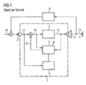
- FIG. 1 shows the principle of acoustic feedback.
- a hearing device 1 has a microphone 2, which receives an acoustic useful signal 10, converts it into an electrical microphone signal 11 and emits it to a signal processing unit 3.
- the microphone signal 11 is, among other things, processed, amplified and delivered to a receiver 4 as an electrical receiver signal 12.
- the electrical receiver signal 12 is again converted into an acoustic output signal 13 and delivered to the eardrum 7 of a hearing aid wearer.
- the acoustic feedback path 14 is reproduced digitally in the hearing aid 1.
- the replication takes place, for example, by means of an adaptive compensation filter 5, which is fed by the receiver signal 12.
- a filtered compensation signal 15 is subtracted from the microphone signal 11.
- the effect of the acoustic feedback path 14 is thereby canceled and there is a feedback-free input signal 16 for the signal processing unit.
- the microphone signal 11 is evaluated with the aid of a detection unit 6 and examined for possible feedback.
- artefacts can also be created, however, since additional signal components are generated or feedback whistling occurs in the case of an adaptive compensation filter which is not set optimally.
- EP 1 033 063 B1 discloses a hearing aid with a feedback suppression, wherein two parallel adaptive compensation filters are used to improve the feedback suppression.
- a high correlation between the useful signal 10 and the feedback signal 14 represents a major problem for optimal feedback suppression because the correlation also attacks input signal components and erroneous adaptions of the compensation filter occur.
- a solution to this problem will be found in JASA Vol. 94, pt.6, 1993-Dec., 3248 ff. disclosed.
- a useful signal is decorrelated by a feedback interference signal by the frequency of the output signal of a hearing aid and thus the frequency of the feedback signal is shifted relative to the frequency of the useful signal.
- FIG. 2 is shown as an example of the frequency response of a crossover of a hearing aid of the type Butterworth 9th order with a cut-off frequency GF of 900 Hz.
- the curves K1, K2 show the amplitude D in dB as a function of the frequency F in Hz in the range 0 to 1150 Hz.
- the curve K1 shows a low-pass characteristic and the curve K2 a high-pass characteristic.
- the cumulative curve K3 from the curves K1 and K2 gives a flat, constant frequency response.
- the curve K4 shows one with respect to the curve K2 high-pass characteristic shifted by 25 Hz to higher frequencies.
- the invention claims a hearing aid with an adaptive feedback suppression unit and a signal processing unit.
- the hearing aid also comprises a low-pass filter characterized by a first cut-off frequency, which decouples a low-frequency signal component from an output signal of the signal processing unit, a high-pass filter characterized by a second cut-off frequency which decouples a high-frequency signal component from the output signal of the signal processing unit, and a frequency-shifting unit which determines the frequency of the high-frequency signal component high-frequency signal component shifts to higher frequencies.
- There is a predeterminable distance or gap between the first and the second cutoff frequency Due to the different cutoff frequencies, signal distortions caused by a frequency shift are effectively suppressed. The reason is that this results in less overlapping shifted and unshifted signal components. Thus, feedback cancellation can operate continuously at higher frequencies. The suppression then takes place quickly.
- the distance between 20 Hz and 50 Hz can be large. Experiments have shown that a distance of the cutoff frequencies in this size is sufficient.
- the frequency shift of the high-frequency signal component is 10 Hz to 30 Hz. This optimizes acoustic feedback cancellation.
- the hearing device comprises an adder, in which the low-frequency signal component and the frequency-shifted high-frequency signal component are summed, wherein an output signal of the hearing device is formed.
- the low-pass filter and / or the high-pass filter may be formed as a Cauer filter (also referred to as an elliptic filter).
- a Cauer filter also referred to as an elliptic filter.
- the large slew rate of this type of filter effectively prevents signal distortion.
- the distance of the cut-off frequencies between 20 Hz and 50 Hz can be selected.
- the frequency of the high-frequency signal component can be shifted by 10 Hz to 30 Hz.
- the method preferably also comprises an addition of the low-frequency signal component with the frequency-shifted high-frequency signal component, wherein an output signal of the hearing device is formed.
- the low-pass filter and / or the high-pass filter can be executed as a Cauer filter.
- FIG. 3 shows a hearing aid 1 with an acoustic input signal 101 receiving microphone 2 and with an acoustic output 13 donating handset 4. As described above, a portion of the output signal 13 is fed back via a feedback path 14 to the microphone 2 of the hearing aid 1, wherein it is with a User signal 10 superimposed on the input signal 101.
- the microphone 2 converts the acoustic Input signal 101 into an electrical microphone signal 102 um.
- Any occurring acoustic feedbacks are detected by means of a feedback suppression unit 17, simulated from an earphone input signal 108 and added as an inverted feedback suppression signal 109 to the microphone signal 102 in a second adder 22.
- a feedback suppression unit 17 simulated from an earphone input signal 108 and added as an inverted feedback suppression signal 109 to the microphone signal 102 in a second adder 22.
- this results in a feedback-suppressed microphone signal 107, which is supplied to a signal processing unit 3.
- An output signal 103 of the signal processing unit 3 is supplied to the input of a crossover with a low-pass filter 18 and a high-pass filter 19.
- a low-pass output signal 105 At the output of the low-pass filter 18 is a low-pass output signal 105 and at the output of the high-pass filter 19 is a high-pass output signal 104 is available.
- the high-pass output signal 104 is shifted by means of a frequency shift unit 20 by about 10 Hz to 30 Hz to higher frequencies.
- the frequency-shifted high-pass output signal 106 is added to the low-pass output signal 105 in a first adder 21.
- a receiver input signal 108 is available, which is converted by the receiver 4 into the acoustic output signal 13.
- the low-pass filter 18 and the high-pass filter 19 have different limit frequencies GF1, GF2, whereby almost no disturbing interference effects of original and shifted in frequency signal components can occur.
- the two filters 18, 19 are elliptical filters, also called Cauer filters. They have a particularly steep edge, whereby an unwanted signal overlay in the filter overlap area can be extremely reduced in addition to the different choice of cutoff frequencies.
- the invention can be used both for hearing aids with one and with several microphones.
- several microphones there are also a plurality of feedback suppression units and a plurality of crossovers according to the invention, which are fed by different signal-processed microphone signals.
- FIG. 4 Frequency responses K5, K6, K7, K8, K9, K10 corresponding Cauer filter used according to the invention are shown.
- the two diagrams of FIG. 4 show the amplitude D in dB as a function of the frequency F in kHz for a frequency range from 650 Hz to 1150 Hz.
- the upper diagram of the FIG. 4 shows the frequency responses K5, K6 first Cauer filter with a narrow and deep notch of the sum frequency response K7 due to a corresponding formation of the first Cauer filter.
- the distance between the first limit frequency GF1 of the low pass (curve K5) and the second limit frequency GF2 of the high pass (curve K6) is chosen to be relatively small.
- the first limit frequency GF1 is about 890 Hz
- the second limit frequency GF2 is about 910 Hz.
- the lower diagram of the FIG. 4 shows the frequency responses K8, K9 second Cauer filter with a wider and less deep notch of the sum frequency response K10 due to a corresponding formation of the second Cauer filter.
- the gap between the first limit frequency GF1 of the low pass (curve K8) and the second limit frequency GF2 of the high pass (curve K9) is chosen larger.
- the first limit frequency GF1 is about 880 Hz and the second limit frequency GF2 is about 920 Hz.
Description
Die Erfindung betrifft ein Verfahren zum Betrieb eines Hörgeräts und ein Hörgerät mit einer verbesserten Rückkopplungsunterdrückung durch den Einsatz einer optimierten Frequenzweiche.The invention relates to a method for operating a hearing device and a hearing device with improved feedback suppression by the use of an optimized crossover network.
Ein häufiges Problem bei Hörgeräten ist die Rückkopplung zwischen dem Ausgang des Hörgeräts und dem Eingang, die sich als Pfeifen störend bemerkbar macht.
Das Problem besteht nun darin, dass ein Teil des akustischen Ausgangssignals 13 über einen akustischen Rückkopplungspfad 14 zum Eingang des Hörgeräts 1 gelangt, wo es sich mit dem Nutzsignal 10 überlagert und als Summensignal vom Mikrofon 2 aufgenommen wird. Bei einer ungünstigen Phasenlage und Amplitude des rückgekoppelten Ausgangssignals kommt es zu dem störenden Rückkopplungspfeifen. Insbesondere bei einer offenen Hörgeräteversorgung ist die Dämpfung der akustischen Rückkopplung gering, wodurch das Problem verschärft wird.The problem now is that a part of the
Zur Lösung stehen seit einiger Zeit adaptive Systeme zur Rückkopplungsunterdrückung zur Verfügung. Dazu wird der akustische Rückkopplungspfad 14 im Hörgerät 1 digital nachgebildet. Die Nachbildung erfolgt beispielsweise mittels eines adaptiven Kompensationsfilters 5, das von dem Hörersignal 12 gespeist wird. Nach einer Filterung im Kompensationsfilter 5 wird ein gefiltertes Kompensationssignal 15 vom Mikrofonsignal 11 subtrahiert. Im Idealfall wird die Wirkung des akustischen Rückkopplungspfads 14 dadurch aufgehoben und es entsteht ein rückkopplungsfreies Eingangssignal 16 für die Signalverarbeitungseinheit 3.For some time adaptive systems for feedback suppression have been available. For this purpose, the
Für eine effektive Rückkopplungsunterdrückung ist eine Regelung bzw. Anpassung von Filterkoeffizienten des adaptiven Kompensationsfilters 5 erforderlich. Dazu wird mit Hilfe einer Detektionseinheit 6 das Mikrofonsignal 11 ausgewertet und auf mögliche Rückkopplungen untersucht. Durch die Regelung bzw. Anpassung der Filterkoeffizienten können aber auch Artefakte entstehen, da bei einem nicht optimal eingestellten adaptiven Kompensationsfilter 5 zusätzliche Signalkomponenten erzeugt werden oder ein Rückkopplungspfeifen auftritt. In der
Eine hohe Korrelation zwischen Nutzsignal 10 und Rückkopplungssignal 14 stellt für eine optimale Rückkopplungsunterdrückung ein großes Problem dar, weil durch die Korrelation auch Eingangssignalkomponenten angegriffen werden und Fehladaptionen des Kompensationsfilters auftreten.A high correlation between the
Eine Lösung dieses Problems wird in
Leider verursachen die Frequenzverschiebungen bzw. - verzerrungen auch deutlich wahrnehmbare Artefakte. Eine Verzerrung bei tiefen Frequenzen ist in der Regel nicht möglich, da das menschliche Gehör im tiefen Frequenzbereich sehr empfindlich auf Verzerrungen reagiert. Daher werden meist nur die hohen Frequenzen verschoben. Trotzdem kann es dabei zu einer hörbaren "Verstimmung" des Nutzsignals kommen.Unfortunately, the frequency shifts or distortions also cause noticeable artifacts. Distortion at low frequencies is usually not possible because human hearing in the low frequency range is very sensitive reacted to distortions. Therefore, usually only the high frequencies are shifted. Nevertheless, this can lead to an audible "detuning" of the useful signal.
Wesentlich unangenehmer sind Überlagerungsartefakte, bei denen ein in der Frequenz verschobene Signal und ein unverschobene Signal gleichzeitig wahrgenommen werden, was bei tonalen Signalen zu einer deutlichen Modulation bzw. Schwebung oder einer Rauhigkeit führt. Nahezu unvermeidlich sind akustische Überlagerungen, die durch den Zufluss von Direktschall, beispielsweise durch das Vent, erfolgen.Considerably more disagreeable are overlay artefacts in which a frequency shifted signal and an unshifted signal are simultaneously perceived, resulting in tonal signals to a significant modulation or beating or roughness. Almost inevitable are acoustic overlays, which take place by the inflow of direct sound, for example by the Vent.
Bauartenbedingt kann es aber auch zu Überlagerungen durch nicht ideale Split-Band Filter kommen. Um nur hochfrequente Frequenzanteile verschieben zu können, müssen diese von den niederfrequenten Anteilen getrennt werden. Dazu wird eine Frequenzweiche, auch Split-Band Filter genannt, benötigt. Die Frequenzweiche kann aber keine ideale Trennung vollziehen, wodurch es im Bereich der Grenzfrequenz der Frequenzweiche zu störenden Überlagerungen kommt.Depending on the design, however, it may also come to superpositions by non-ideal split-band filter. In order to move only high-frequency components, they must be separated from the low-frequency components. This requires a crossover network, also known as a split-band filter. However, the crossover can not perform ideal separation, which leads to disturbing superpositions in the range of the cutoff frequency of the crossover.
Abhängig von der Frequenzverschiebung werden diese Überlagerungen als Amplitudenmodulation oder als Signalrauhigkeit wahrgenommen. In allen beschriebenen Fällen sind die Überlagerungen störend, besonders wenn es sich bei einem Eingangssignal um Musik oder allgemeiner um tonale Signale handelt.Depending on the frequency shift, these superimpositions are perceived as amplitude modulation or signal roughness. In all cases described, the overlays are annoying, especially when an input signal is music or, more generally, tonal signals.
Bekannte Frequenzweichen in Hörgeräten sind vom Typ Butterworth. Sie sind nicht ideal und haben bei ihrer Grenzfrequenz GF eine endliche Frequenzüberlappung. In
Bei einer Addition der Signalanteile entsprechend der Kurven K1 und K3 kommt es vor allem im Bereich der Grenzfrequenz GF zu nicht zu vernachlässigenden Überlagerungen von in der Frequenz verschobenen und unverschobenen Signalanteilen, was in einem Ausgangssignal des Hörgeräts als Modulation oder starke Rauhigkeit wahrgenommen wird. Beide Wirkungen sind störend und fallen in der Wahrnehmung durch einen Hörgeräteträger meist deutlich stärker auf als die Frequenzverschiebung.Upon addition of the signal components corresponding to the curves K1 and K3, notably negligible superimpositions of frequency-shifted and unshifted signal components occur, especially in the region of the limit frequency GF, which is perceived as modulation or pronounced roughness in an output signal of the hearing aid. Both effects are disturbing and usually noticeably more noticeable in the perception by a hearing aid wearer than the frequency shift.
Es ist Aufgabe der Erfindung, die Wahrnehmung von Artefakten einer Frequenzverschiebung bei Hörgeräten zu verringern.It is an object of the invention to reduce the perception of artifacts of a frequency shift in hearing aids.
Gemäß der Erfindung wird die gestellte Aufgabe mit dem Hörgerät und dem Verfahren der unabhängigen Patentansprüche gelöst.According to the invention, the stated object is achieved with the hearing aid and the method of the independent claims.
Die Erfindung beansprucht ein Hörgerät mit einer adaptiven Rückkopplungsunterdrückungseinheit und einer Signalverarbeitungseinheit. Das Hörgerät umfasst außerdem ein durch eine erste Grenzfrequenz charakterisiertes Tiefpassfilter, das aus einem Ausgangssignal der Signalverarbeitungseinheit einen niederfrequenten Signalanteil auskoppelt, ein durch eine zweite Grenzfrequenz charakterisiertes Hochpassfilter, das aus dem Ausgangssignal der Signalverarbeitungseinheit einen hochfrequenten Signalanteil auskoppelt, und eine Frequenzverschiebeeinheit, welche die Frequenz des hochfrequenten Signalanteils zu höheren Frequenzen verschiebt. Zwischen der ersten und der zweiten Grenzfrequenz besteht ein vorgebbarer Abstand bzw. eine Lücke. Durch die unterschiedlichen Grenzfrequenzen werden durch eine Frequenzverschiebung verursachte Signalverzerrungen effektiv unterdrückt. Grund ist, dass so sich weniger überlappende verschobene und unverschobene Signalanteile entstehen. Somit kann eine Rückkopplungsunterdrückung bei höheren Frequenzen kontinuierlich arbeiten. Die Unterdrückung erfolgt dann schnell.The invention claims a hearing aid with an adaptive feedback suppression unit and a signal processing unit. The hearing aid also comprises a low-pass filter characterized by a first cut-off frequency, which decouples a low-frequency signal component from an output signal of the signal processing unit, a high-pass filter characterized by a second cut-off frequency which decouples a high-frequency signal component from the output signal of the signal processing unit, and a frequency-shifting unit which determines the frequency of the high-frequency signal component high-frequency signal component shifts to higher frequencies. There is a predeterminable distance or gap between the first and the second cutoff frequency. Due to the different cutoff frequencies, signal distortions caused by a frequency shift are effectively suppressed. The reason is that this results in less overlapping shifted and unshifted signal components. Thus, feedback cancellation can operate continuously at higher frequencies. The suppression then takes place quickly.
In einer Weiterbildung kann der Abstand zwischen 20 Hz und 50 Hz groß sein. Versuche haben gezeigt, dass ein Abstand der Grenzfrequenzen in dieser Größe ausreichend ist.In a further development, the distance between 20 Hz and 50 Hz can be large. Experiments have shown that a distance of the cutoff frequencies in this size is sufficient.
In einer weiteren Ausführungsform der Erfindung kann die Frequenzverschiebung des hochfrequenten Signalanteils 10 Hz bis 30 Hz beträgt. Dadurch wird eine akustische Rückkopplungsunterdrückung optimiert.In a further embodiment of the invention, the frequency shift of the high-frequency signal component is 10 Hz to 30 Hz. This optimizes acoustic feedback cancellation.
Des Weiteren umfasst das Hörgerät einen Addierer, in dem der niederfrequente Signalanteil und der in der Frequenz verschobene hochfrequente Signalanteil summiert werden, wobei ein Ausgangssignal des Hörgeräts gebildet wird.Furthermore, the hearing device comprises an adder, in which the low-frequency signal component and the frequency-shifted high-frequency signal component are summed, wherein an output signal of the hearing device is formed.
Vorzugsweise können das Tiefpassfilter und/oder das Hochpassfilter als Cauer-Filter (auch als elliptisches Filter bezeichnet) ausgebildet sein. Durch die große Flankensteilheit dieses Filtertyps werden Signalverzerrungen effektiver verhindert.Preferably, the low-pass filter and / or the high-pass filter may be formed as a Cauer filter (also referred to as an elliptic filter). The large slew rate of this type of filter effectively prevents signal distortion.
Die Erfindung beansprucht auch ein Verfahren zur Frequenzverschiebung in einem Hörgerät. Das Verfahren umfasst die folgenden Schritte:
- Auskoppeln eines niederfrequenten Signalanteils aus einem signalverarbeiteten Mikrofonsignal (am Ausgang einer Signalverarbeitungseinheit) durch ein durch eine erste Grenzfrequenz charakterisierten Tiefpassfilter,
- Auskoppeln eines hochfrequenten Signalanteils aus dem signalverarbeiteten Mikrofonsignal (am Ausgang der Signalverarbeitungseinheit) durch ein durch eine zweite Grenzfrequenz charakterisierten Hochpassfilter, wobei zwischen der ersten und der zweiten Grenzfrequenz ein vorgebbarer Abstand bzw. eine Lücke vorhanden ist, und
- Verschieben der Frequenz des hochfrequenten Signalanteils zu höheren Frequenzen,
- Decoupling a low-frequency signal component from a signal-processed microphone signal (at the output of a signal processing unit) by a low-pass filter characterized by a first cutoff frequency,
- Decoupling a high-frequency signal component from the signal-processed microphone signal (at the output of the signal processing unit) by a characterized by a second cutoff frequency high-pass filter, wherein between the first and the second cutoff frequency, a predetermined distance or a gap is present, and
- Shifting the frequency of the high-frequency signal component to higher frequencies,
In einer Weiterbildung des Verfahrens kann der Abstand der Grenzfrequenzen zwischen 20 Hz und 50 Hz gewählt werden.In a further development of the method, the distance of the cut-off frequencies between 20 Hz and 50 Hz can be selected.
In einer weiteren Ausführungsform des Verfahrens kann die Frequenz des hochfrequenten Signalanteils um 10 Hz bis 30 Hz verschoben werden.In a further embodiment of the method, the frequency of the high-frequency signal component can be shifted by 10 Hz to 30 Hz.
Das Verfahren umfasst vorzugsweise auch eine Addition des niederfrequenten Signalanteils mit dem in der Frequenz verschobenen hochfrequenten Signalanteil, wobei ein Ausgangssignal des Hörgeräts gebildet wird.The method preferably also comprises an addition of the low-frequency signal component with the frequency-shifted high-frequency signal component, wherein an output signal of the hearing device is formed.
Außerdem kann das Tiefpassfilter und/oder das Hochpassfilter als Cauer Filter ausgeführt werden.In addition, the low-pass filter and / or the high-pass filter can be executed as a Cauer filter.
Weitere Besonderheiten und Vorteile der Erfindung werden aus den nachfolgenden Erläuterungen zu Ausführungsbeispielen anhand von schematischen Zeichnungen ersichtlich.Other features and advantages of the invention will become apparent from the following explanations to exemplary embodiments with reference to schematic drawings.
Es zeigen:
- Figur 1:
- ein Blockschaltbild eines Hörgeräts mit akustischer Rückkopplung und Rückkopplungsunterdrückung gemäß Stand der Technik,
- Figur 2:
- einen Frequenzgang einer Frequenzweiche vom Typ Butterworth 9. Ordnung gemäß Stand der Technik,
- Figur 3:
- ein Blockschaltbild eines Hörgeräts mit einer Rückkopplungsunterdrückung und einer Frequenzweiche und
- Figur 4:
- Frequenzgänge zweier Cauer-Filter.
- FIG. 1:
- a block diagram of a hearing aid with acoustic feedback and feedback suppression according to the prior art,
- FIG. 2:
- a frequency response of a crossover type Butterworth 9th order according to the prior art,
- FIG. 3:
- a block diagram of a hearing aid with a feedback suppression and a crossover and
- FIG. 4:
- Frequency responses of two Cauer filters.
Etwaige auftretende akustische Rückkopplungen werden mit Hilfe einer Rückkopplungsunterdrückungseinheit 17 erkannt, aus einem Hörereingangssignal 108 nachgebildet und als invertiertes Rückkopplungsunterdrückungssignal 109 zum Mikrofonsignal 102 in einem zweiten Addierer 22 addiert. Am Ausgang des zweiten Addierers 22 entsteht so ein rückkopplungsunterdrücktes Mikrofonsignal 107, das einer Signalverarbeitungseinheit 3 zugeführt wird. Ein Ausgangssignal 103 der Signalverarbeitungseinheit 3 wird dem Eingang einer Frequenzweiche mit einem Tiefpassfilter 18 und einem Hochpassfilter 19 zugeführt.Any occurring acoustic feedbacks are detected by means of a
Am Ausgang des Tiefpassfilters 18 steht ein Tiefpassausgangssignal 105 und am Ausgang des Hochpassfilters 19 steht ein Hochpassausgangssignal 104 zur Verfügung. Das Hochpassausgangssignal 104 wird mit Hilfe einer Frequenzverschiebeeinheit 20 um etwa 10 Hz bis 30 Hz zu höheren Frequenzen hin verschoben. Das frequenzverschobene Hochpassausgangssignal 106 wird in einem ersten Addierer 21 zum Tiefpassausgangssignal 105 addiert.At the output of the low-
Am Ausgang des ersten Addieres 21 steht ein Hörereingangssignal 108 zur Verfügung, das durch den Hörer 4 in das akustische Ausgangssignal 13 gewandelt wird.At the output of the
Erfindungsgemäß haben das Tiefpassfilter 18 und das Hochpassfilter 19 unterschiedliche Grenzfrequenzen GF1, GF2, wodurch nahezu keine störenden Überlagerungseffekte von originalen und in der Frequenz verschobenen Signalkomponenten auftreten können. Vorzugsweise sind die beiden Filter 18, 19 elliptische Filter, auch Cauer-Filter genannt. Sie besitzen eine besonders steile Flanke, wodurch eine ungewollte Signalüberlagerung im Filterüberlappungsbereich zusätzlich zur unterschiedlichen Wahl der Grenzfrequenzen extrem reduziert werden kann.According to the invention, the low-
Die Erfindung ist sowohl für Hörgeräte mit einem als auch mit mehreren Mikrofonen einsetzbar. Bei mehreren Mikrofonen gibt es auch mehrere Rückkopplungsunterdrückungseinheiten und mehrere erfindungsgemäße Frequenzweichen, die von unterschiedlichen signalverarbeiteten Mikrofonsignalen gespeist werden.The invention can be used both for hearing aids with one and with several microphones. In the case of several microphones, there are also a plurality of feedback suppression units and a plurality of crossovers according to the invention, which are fed by different signal-processed microphone signals.
In
Das obere Diagramm der
Das untere Diagramm der
Versuche haben gezeigt, dass die Erfindung wesentlich geringere Signalstörungen bei Hörgeräten mit Frequenzverschiebung erzeugt, weil keine doppelten Frequenzkomponenten auftreten, die einen rauen Klang verursachen würden.Experiments have shown that the invention produces significantly less signal interference in frequency response hearing aids because there are no duplicate frequency components that would cause a harsh sound.
- 11
- Hörgeräthearing Aid
- 22
- Mikrofonmicrophone
- 33
- SignalverarbeitungseinheitSignal processing unit
- 44
- Hörerreceiver
- 55
- Kompensationsfilterscompensating filter
- 66
- Detektionseinheitdetection unit
- 77
- Trommelfelleardrum
- 1010
- Nutzsignalpayload
- 1111
- Mikrofonsignalmicrophone signal
- 1212
- Hörersignalearpiece signal
- 1313
- Ausgangssignaloutput
- 1414
- RückkopplungspfadFeedback path
- 1515
- Kompensationssignalcompensation signal
- 1616
- Eingangssignalinput
- 1717
- RückkopplungsunterdrückungseinheitFeedback suppression unit
- 1818
- Tiefpassfilter mit erster Grenzfrequenz GF1Low-pass filter with first cut-off frequency GF1
- 1919
- Hochpassfilter mit zweiter Grenzfrequenz GF2High-pass filter with second cut-off frequency GF2
- 2020
- FrequenzverschiebeeinheitFrequency displacement unit
- 2121
- Erster AddiererFirst adder
- 2222
- Zweiter AddiererSecond adder
- 101101
- Eingangssignal mit akustischen RückkopplungenInput signal with acoustic feedback
- 102102
- Mikrofonsignalmicrophone signal
- 103103
-
Ausgangssignal der Signalverarbeitungseinheit 3Output signal of the
signal processing unit 3 - 104104
- HochpassausgangssignalHigh-pass output
- 105105
- TiefpassausgangssignalLow pass output
- 106106
- Frequenzverschobenes HochpassausgangssignalFrequency-shifted high-pass output signal
- 107107
- Rückkopplungsunterdrücktes MikrofonsignalFeedback suppressed microphone signal
- 108108
- HörereingangssignalReceiver input signal
- 109109
- RückkopplungsunterdrückungssignalFeedback suppression signal
- DD
- Dämpfung in dBDamping in dB
- FF
- Frequenz in kHzFrequency in kHz
- GFGF
- Grenzfrequenz der Butterworth-FilterCutoff frequency of Butterworth filters
- GF1GF1
- Erste GrenzfrequenzFirst cutoff frequency
- GF2GF2
- Zweite GrenzfrequenzSecond cutoff frequency
- K1K1
- Frequenzgang eines Butterworth-TiefpassfiltersFrequency response of a Butterworth low-pass filter
- K2K2
- Frequenzgang eines Butterworth-HochpassfiltersFrequency response of a Butterworth high pass filter
- K3K3
- Summen-Frequenzgang der beiden Butterworth-FilterTotal frequency response of the two Butterworth filters
- K4K4
- Frequenzgang eines in der Frequenz verschobenen Butterworth-HochpassfiltersFrequency response of a shifted in frequency Butterworth high-pass filter
- K5K5
- Frequenzgang eines ersten Cauer-TiefpassfiltersFrequency response of a first Cauer low-pass filter
- K6K6
- Frequenzgang eines ersten Cauer-HochpassfiltersFrequency response of a first Cauer high pass filter
- K7K7
- Summen-Frequenzgang der beiden ersten Cauer-Filter K5, K6Sum frequency response of the first two Cauer filters K5, K6
- K8K8
- Frequenzgang eines zweiten Cauer-TiefpassfiltersFrequency response of a second Cauer low-pass filter
- K9K9
- Frequenzgang eines zweiten Cauer-HochpassfiltersFrequency response of a second Cauer high pass filter
- K10K10
- Summen-Frequenzgang der beiden zweiten Cauer-Filter K5, K6Sum frequency response of the two second Cauer filters K5, K6
Claims (8)
- Hearing device (1) with- a feedback suppression unit (17) and- a signal processing unit (3)characterised by:- a low-pass filter (18) characterised by a first cut-off frequency (GF1), which couples a low-frequency signal component (105) out of an output signal (103) of the signal processing unit (3),- a high-pass filter (18) characterised by a second cut-off frequency (GF2), which couples a high-frequency signal component (104) out of the output signal (103) of the signal processing unit (3), and- a frequency shift unit (20), which shifts the frequency (F) of the high-frequency signal component (104) to higher frequencies, and- a first adder (21), in which the low-frequency signal component (105) and the high-frequency signal component (106) shifted in frequency are summed, from which an output signal (13) of the hearing device (1) is able to be formed,- wherein the first and the second cut-off frequency (GF1, GF2) are different.
- Hearing device according to claim 1
characterised in that
the distance between the first and the second cut-off frequency (GF1, GF2) is between 20 Hz and 50 Hz in size. - Hearing device according to claim 1 or 2,
characterised in that
the frequency shift of the high-frequency signal component (104) amounts to 10 Hz to 30 Hz. - Hearing device according to one of the previous claims,
characterised in that
the low-pass filter (18) and/or the high-pass filter (19) are embodied as Cauer filters. - Method for frequency shifting in a hearing device (1),
characterised by- a coupling-out of a low-frequency signal component (105) from a signal-processed microphone signal (103) by a low-pass filter (18) characterized by a first cut-off frequency (GF1),- a coupling-out of a high-frequency signal component (104) from the signal-processed microphone signal (103) by a high-pass filter (19) characterized by a second cut-off frequency (GF2)- wherein the first and the second cut-off frequency (GF1, GF2) are different- a shifting of the high-frequency signal component (104) to higher frequencies.- an addition of the low-frequency signal component (105) and the high-frequency signal component (106) shifted in frequency (F),- wherein an output signal (13) of the hearing device (1) is formed. - Method according to claim 5,
characterised in that
the distance between the first and the second cut-off frequency (GF1, GF2) is selected between 20 Hz and 50 Hz. - Method according to claim 5 or 6,
characterised in that
the frequencies (F) of the high-frequency signal component (104) are shifted by 10 Hz to 30 Hz. - Method according to one of claims 5 to 7,
characterised in that
the low-pass filter (18) and/or the high-pass filter (19) are embodied as Cauer filters.
Applications Claiming Priority (2)
| Application Number | Priority Date | Filing Date | Title |
|---|---|---|---|
| US29937010P | 2010-01-29 | 2010-01-29 | |
| DE102010006154A DE102010006154B4 (en) | 2010-01-29 | 2010-01-29 | Hearing aid with frequency shift and associated method |
Publications (3)
| Publication Number | Publication Date |
|---|---|
| EP2360945A2 EP2360945A2 (en) | 2011-08-24 |
| EP2360945A3 EP2360945A3 (en) | 2013-07-10 |
| EP2360945B1 true EP2360945B1 (en) | 2014-09-10 |
Family
ID=43332772
Family Applications (1)
| Application Number | Title | Priority Date | Filing Date |
|---|---|---|---|
| EP10187394.1A Revoked EP2360945B1 (en) | 2010-01-29 | 2010-10-13 | Hearing aid with frequency shift and accompanying method |
Country Status (4)
| Country | Link |
|---|---|
| US (1) | US8538053B2 (en) |
| EP (1) | EP2360945B1 (en) |
| DE (1) | DE102010006154B4 (en) |
| DK (1) | DK2360945T3 (en) |
Families Citing this family (5)
| Publication number | Priority date | Publication date | Assignee | Title |
|---|---|---|---|---|
| DE102010025918B4 (en) | 2010-07-02 | 2013-06-06 | Siemens Medical Instruments Pte. Ltd. | Method for operating a hearing aid and hearing aid with variable frequency shift |
| DK2590437T3 (en) | 2011-11-03 | 2016-01-11 | Sivantos Pte Ltd | Periodic adaptation of a feedback suppression device |
| US9179222B2 (en) | 2013-06-06 | 2015-11-03 | Cochlear Limited | Signal processing for hearing prostheses |
| US10499165B2 (en) | 2016-05-16 | 2019-12-03 | Intricon Corporation | Feedback reduction for high frequencies |
| DE102017200320A1 (en) * | 2017-01-11 | 2018-07-12 | Sivantos Pte. Ltd. | Method for frequency distortion of an audio signal |
Family Cites Families (16)
| Publication number | Priority date | Publication date | Assignee | Title |
|---|---|---|---|---|
| US5121009A (en) * | 1990-06-15 | 1992-06-09 | Novatel Communications Ltd. | Linear phase low pass filter |
| US6072884A (en) * | 1997-11-18 | 2000-06-06 | Audiologic Hearing Systems Lp | Feedback cancellation apparatus and methods |
| US6097824A (en) * | 1997-06-06 | 2000-08-01 | Audiologic, Incorporated | Continuous frequency dynamic range audio compressor |
| US6434246B1 (en) * | 1995-10-10 | 2002-08-13 | Gn Resound As | Apparatus and methods for combining audio compression and feedback cancellation in a hearing aid |
| AU7118696A (en) * | 1995-10-10 | 1997-04-30 | Audiologic, Inc. | Digital signal processing hearing aid with processing strategy selection |
| US6498858B2 (en) * | 1997-11-18 | 2002-12-24 | Gn Resound A/S | Feedback cancellation improvements |
| JP3381062B2 (en) * | 1999-06-22 | 2003-02-24 | 日本マランツ株式会社 | Stereo signal processor |
| US6831986B2 (en) * | 2000-12-21 | 2004-12-14 | Gn Resound A/S | Feedback cancellation in a hearing aid with reduced sensitivity to low-frequency tonal inputs |
| EP1438873A1 (en) * | 2001-10-17 | 2004-07-21 | Oticon A/S | Improved hearing aid |
| DE10244184B3 (en) * | 2002-09-23 | 2004-04-15 | Siemens Audiologische Technik Gmbh | Feedback compensation for hearing aids with system distance estimation |
| US20040252853A1 (en) * | 2003-05-27 | 2004-12-16 | Blamey Peter J. | Oscillation suppression |
| AU2003236382B2 (en) * | 2003-08-20 | 2011-02-24 | Phonak Ag | Feedback suppression in sound signal processing using frequency transposition |
| DE102006020832B4 (en) * | 2006-05-04 | 2016-10-27 | Sivantos Gmbh | Method for suppressing feedback in hearing devices |
| EP2369859B1 (en) | 2008-05-30 | 2016-12-21 | Sonova AG | Method for adapting sound in a hearing aid device by frequency modification and such a device |
| EP2309776B1 (en) * | 2009-09-14 | 2014-07-23 | GN Resound A/S | Hearing aid with means for adaptive feedback compensation |
| US8564436B2 (en) * | 2010-03-04 | 2013-10-22 | Victoria A. Oleen | Wallet |
-
2010
- 2010-01-29 DE DE102010006154A patent/DE102010006154B4/en active Active
- 2010-10-13 EP EP10187394.1A patent/EP2360945B1/en not_active Revoked
- 2010-10-13 DK DK10187394.1T patent/DK2360945T3/en active
-
2011
- 2011-01-28 US US13/016,422 patent/US8538053B2/en active Active
Also Published As
| Publication number | Publication date |
|---|---|
| EP2360945A3 (en) | 2013-07-10 |
| DK2360945T3 (en) | 2014-12-15 |
| DE102010006154A1 (en) | 2011-08-04 |
| EP2360945A2 (en) | 2011-08-24 |
| DE102010006154B4 (en) | 2012-01-19 |
| US20110194714A1 (en) | 2011-08-11 |
| US8538053B2 (en) | 2013-09-17 |
Similar Documents
| Publication | Publication Date | Title |
|---|---|---|
| EP2244491B2 (en) | Method for operating a hearing aid with feedback suppression and hearing aid with a diplexer | |
| EP2357850B1 (en) | Method and hearing aid for recognising and suppressing feedback from a directional microphone | |
| DE102005047047A1 (en) | Microphone calibration on a RGSC beamformer | |
| DE102006047986B4 (en) | Processing an input signal in a hearing aid | |
| EP2360945B1 (en) | Hearing aid with frequency shift and accompanying method | |
| EP2437258B1 (en) | Method and device for frequency compression with selective frequency shifting | |
| EP2988529B1 (en) | Adaptive separation frequency in hearing aids | |
| DE102009010892A1 (en) | Apparatus and method for reducing impact sound effects in hearing devices with active occlusion reduction | |
| DE102011006129B4 (en) | Hearing device with feedback suppression device and method for operating the hearing device | |
| DE102009036610B4 (en) | Filter bank arrangement for a hearing device | |
| DE10357800B3 (en) | Hearing aid with noise suppression has signal processing device for simulating transmission function of acoustic path that applies function to noise signal to form noise output signal that is combined with useful output signal | |
| DE102013207403B3 (en) | Method for controlling an adaptation step size and hearing device | |
| DE102009021310B4 (en) | Binaural hearing apparatus and method for operating a binaural hearing apparatus with frequency distortion | |
| EP2595414A1 (en) | Hearing aid with a device for reducing a microphone noise and method for reducing a microphone noise | |
| DE102010025918B4 (en) | Method for operating a hearing aid and hearing aid with variable frequency shift | |
| EP2129167B1 (en) | Method for operating a hearing device and microphone system for a hearing device | |
| EP3373599A1 (en) | Method for frequency warping of an audio signal and hearing aid operating according to this method | |
| DE102008024534A1 (en) | Hearing device with an equalization filter in the filter bank system | |
| EP2437521B1 (en) | Method for frequency compression with harmonic adjustment and corresponding device | |
| DE102008058496B4 (en) | Filter bank system with specific stop attenuation components for a hearing device | |
| EP3373601B1 (en) | Method for frequency distortion of an audio signal and a hearing aid carrying out this method | |
| DE102018207780B3 (en) | Method for operating a hearing aid |
Legal Events
| Date | Code | Title | Description |
|---|---|---|---|
| PUAI | Public reference made under article 153(3) epc to a published international application that has entered the european phase |
Free format text: ORIGINAL CODE: 0009012 |
|
| AK | Designated contracting states |
Kind code of ref document: A2 Designated state(s): AL AT BE BG CH CY CZ DE DK EE ES FI FR GB GR HR HU IE IS IT LI LT LU LV MC MK MT NL NO PL PT RO RS SE SI SK SM TR |
|
| AX | Request for extension of the european patent |
Extension state: BA ME |
|
| PUAL | Search report despatched |
Free format text: ORIGINAL CODE: 0009013 |
|
| AK | Designated contracting states |
Kind code of ref document: A3 Designated state(s): AL AT BE BG CH CY CZ DE DK EE ES FI FR GB GR HR HU IE IS IT LI LT LU LV MC MK MT NL NO PL PT RO RS SE SI SK SM TR |
|
| AX | Request for extension of the european patent |
Extension state: BA ME |
|
| RIC1 | Information provided on ipc code assigned before grant |
Ipc: H04R 25/00 20060101AFI20130605BHEP |
|
| 17P | Request for examination filed |
Effective date: 20130620 |
|
| RBV | Designated contracting states (corrected) |
Designated state(s): AL AT BE BG CH CY CZ DE DK EE ES FI FR GB GR HR HU IE IS IT LI LT LU LV MC MK MT NL NO PL PT RO RS SE SI SK SM TR |
|
| GRAP | Despatch of communication of intention to grant a patent |
Free format text: ORIGINAL CODE: EPIDOSNIGR1 |
|
| INTG | Intention to grant announced |
Effective date: 20140326 |
|
| GRAS | Grant fee paid |
Free format text: ORIGINAL CODE: EPIDOSNIGR3 |
|
| GRAA | (expected) grant |
Free format text: ORIGINAL CODE: 0009210 |
|
| AK | Designated contracting states |
Kind code of ref document: B1 Designated state(s): AL AT BE BG CH CY CZ DE DK EE ES FI FR GB GR HR HU IE IS IT LI LT LU LV MC MK MT NL NO PL PT RO RS SE SI SK SM TR |
|
| REG | Reference to a national code |
Ref country code: GB Ref legal event code: FG4D Free format text: NOT ENGLISH |
|
| REG | Reference to a national code |
Ref country code: CH Ref legal event code: EP Ref country code: CH Ref legal event code: NV Representative=s name: SIEMENS SCHWEIZ AG, CH |
|
| REG | Reference to a national code |
Ref country code: IE Ref legal event code: FG4D Free format text: LANGUAGE OF EP DOCUMENT: GERMAN |
|
| REG | Reference to a national code |
Ref country code: AT Ref legal event code: REF Ref document number: 687217 Country of ref document: AT Kind code of ref document: T Effective date: 20141015 |
|
| REG | Reference to a national code |
Ref country code: DE Ref legal event code: R096 Ref document number: 502010007848 Country of ref document: DE Effective date: 20141023 |
|
| REG | Reference to a national code |
Ref country code: DK Ref legal event code: T3 Effective date: 20141211 |
|
| PG25 | Lapsed in a contracting state [announced via postgrant information from national office to epo] |
Ref country code: NO Free format text: LAPSE BECAUSE OF FAILURE TO SUBMIT A TRANSLATION OF THE DESCRIPTION OR TO PAY THE FEE WITHIN THE PRESCRIBED TIME-LIMIT Effective date: 20141210 Ref country code: LT Free format text: LAPSE BECAUSE OF FAILURE TO SUBMIT A TRANSLATION OF THE DESCRIPTION OR TO PAY THE FEE WITHIN THE PRESCRIBED TIME-LIMIT Effective date: 20140910 Ref country code: ES Free format text: LAPSE BECAUSE OF FAILURE TO SUBMIT A TRANSLATION OF THE DESCRIPTION OR TO PAY THE FEE WITHIN THE PRESCRIBED TIME-LIMIT Effective date: 20140910 Ref country code: GR Free format text: LAPSE BECAUSE OF FAILURE TO SUBMIT A TRANSLATION OF THE DESCRIPTION OR TO PAY THE FEE WITHIN THE PRESCRIBED TIME-LIMIT Effective date: 20141211 Ref country code: FI Free format text: LAPSE BECAUSE OF FAILURE TO SUBMIT A TRANSLATION OF THE DESCRIPTION OR TO PAY THE FEE WITHIN THE PRESCRIBED TIME-LIMIT Effective date: 20140910 Ref country code: SE Free format text: LAPSE BECAUSE OF FAILURE TO SUBMIT A TRANSLATION OF THE DESCRIPTION OR TO PAY THE FEE WITHIN THE PRESCRIBED TIME-LIMIT Effective date: 20140910 |
|
| REG | Reference to a national code |
Ref country code: NL Ref legal event code: VDEP Effective date: 20140910 |
|
| REG | Reference to a national code |
Ref country code: LT Ref legal event code: MG4D |
|
| PG25 | Lapsed in a contracting state [announced via postgrant information from national office to epo] |
Ref country code: RS Free format text: LAPSE BECAUSE OF FAILURE TO SUBMIT A TRANSLATION OF THE DESCRIPTION OR TO PAY THE FEE WITHIN THE PRESCRIBED TIME-LIMIT Effective date: 20140910 Ref country code: HR Free format text: LAPSE BECAUSE OF FAILURE TO SUBMIT A TRANSLATION OF THE DESCRIPTION OR TO PAY THE FEE WITHIN THE PRESCRIBED TIME-LIMIT Effective date: 20140910 Ref country code: LV Free format text: LAPSE BECAUSE OF FAILURE TO SUBMIT A TRANSLATION OF THE DESCRIPTION OR TO PAY THE FEE WITHIN THE PRESCRIBED TIME-LIMIT Effective date: 20140910 Ref country code: CY Free format text: LAPSE BECAUSE OF FAILURE TO SUBMIT A TRANSLATION OF THE DESCRIPTION OR TO PAY THE FEE WITHIN THE PRESCRIBED TIME-LIMIT Effective date: 20140910 |
|
| PG25 | Lapsed in a contracting state [announced via postgrant information from national office to epo] |
Ref country code: NL Free format text: LAPSE BECAUSE OF FAILURE TO SUBMIT A TRANSLATION OF THE DESCRIPTION OR TO PAY THE FEE WITHIN THE PRESCRIBED TIME-LIMIT Effective date: 20140910 |
|
| REG | Reference to a national code |
Ref country code: DE Ref legal event code: R082 Ref document number: 502010007848 Country of ref document: DE Representative=s name: FDST PATENTANWAELTE FREIER DOERR STAMMLER TSCH, DE |
|
| REG | Reference to a national code |
Ref country code: DE Ref legal event code: R082 Ref document number: 502010007848 Country of ref document: DE Representative=s name: FDST PATENTANWAELTE FREIER DOERR STAMMLER TSCH, DE |
|
| PG25 | Lapsed in a contracting state [announced via postgrant information from national office to epo] |
Ref country code: PT Free format text: LAPSE BECAUSE OF FAILURE TO SUBMIT A TRANSLATION OF THE DESCRIPTION OR TO PAY THE FEE WITHIN THE PRESCRIBED TIME-LIMIT Effective date: 20150112 Ref country code: SK Free format text: LAPSE BECAUSE OF FAILURE TO SUBMIT A TRANSLATION OF THE DESCRIPTION OR TO PAY THE FEE WITHIN THE PRESCRIBED TIME-LIMIT Effective date: 20140910 Ref country code: RO Free format text: LAPSE BECAUSE OF FAILURE TO SUBMIT A TRANSLATION OF THE DESCRIPTION OR TO PAY THE FEE WITHIN THE PRESCRIBED TIME-LIMIT Effective date: 20140910 Ref country code: IS Free format text: LAPSE BECAUSE OF FAILURE TO SUBMIT A TRANSLATION OF THE DESCRIPTION OR TO PAY THE FEE WITHIN THE PRESCRIBED TIME-LIMIT Effective date: 20150110 Ref country code: EE Free format text: LAPSE BECAUSE OF FAILURE TO SUBMIT A TRANSLATION OF THE DESCRIPTION OR TO PAY THE FEE WITHIN THE PRESCRIBED TIME-LIMIT Effective date: 20140910 Ref country code: CZ Free format text: LAPSE BECAUSE OF FAILURE TO SUBMIT A TRANSLATION OF THE DESCRIPTION OR TO PAY THE FEE WITHIN THE PRESCRIBED TIME-LIMIT Effective date: 20140910 |
|
| PG25 | Lapsed in a contracting state [announced via postgrant information from national office to epo] |
Ref country code: PL Free format text: LAPSE BECAUSE OF FAILURE TO SUBMIT A TRANSLATION OF THE DESCRIPTION OR TO PAY THE FEE WITHIN THE PRESCRIBED TIME-LIMIT Effective date: 20140910 |
|
| REG | Reference to a national code |
Ref country code: DE Ref legal event code: R026 Ref document number: 502010007848 Country of ref document: DE |
|
| PLBI | Opposition filed |
Free format text: ORIGINAL CODE: 0009260 |
|
| PG25 | Lapsed in a contracting state [announced via postgrant information from national office to epo] |
Ref country code: BE Free format text: LAPSE BECAUSE OF NON-PAYMENT OF DUE FEES Effective date: 20141031 Ref country code: MC Free format text: LAPSE BECAUSE OF FAILURE TO SUBMIT A TRANSLATION OF THE DESCRIPTION OR TO PAY THE FEE WITHIN THE PRESCRIBED TIME-LIMIT Effective date: 20140910 |
|
| 26 | Opposition filed |
Opponent name: OTICON A/S / WIDEX A/S / GN RESOUND A/S Effective date: 20150610 |
|
| PLAX | Notice of opposition and request to file observation + time limit sent |
Free format text: ORIGINAL CODE: EPIDOSNOBS2 |
|
| REG | Reference to a national code |
Ref country code: IE Ref legal event code: MM4A |
|
| PG25 | Lapsed in a contracting state [announced via postgrant information from national office to epo] |
Ref country code: IT Free format text: LAPSE BECAUSE OF FAILURE TO SUBMIT A TRANSLATION OF THE DESCRIPTION OR TO PAY THE FEE WITHIN THE PRESCRIBED TIME-LIMIT Effective date: 20140910 |
|
| REG | Reference to a national code |
Ref country code: DE Ref legal event code: R082 Ref document number: 502010007848 Country of ref document: DE Representative=s name: FDST PATENTANWAELTE FREIER DOERR STAMMLER TSCH, DE Ref country code: DE Ref legal event code: R081 Ref document number: 502010007848 Country of ref document: DE Owner name: SIVANTOS PTE. LTD., SG Free format text: FORMER OWNER: SIEMENS MEDICAL INSTRUMENTS PTE. LTD., SINGAPORE, SG Ref country code: FR Ref legal event code: PLFP Year of fee payment: 6 |
|
| PG25 | Lapsed in a contracting state [announced via postgrant information from national office to epo] |
Ref country code: IE Free format text: LAPSE BECAUSE OF NON-PAYMENT OF DUE FEES Effective date: 20141013 |
|
| RAP2 | Party data changed (patent owner data changed or rights of a patent transferred) |
Owner name: SIVANTOS PTE. LTD. |
|
| PLAF | Information modified related to communication of a notice of opposition and request to file observations + time limit |
Free format text: ORIGINAL CODE: EPIDOSCOBS2 |
|
| PG25 | Lapsed in a contracting state [announced via postgrant information from national office to epo] |
Ref country code: SI Free format text: LAPSE BECAUSE OF FAILURE TO SUBMIT A TRANSLATION OF THE DESCRIPTION OR TO PAY THE FEE WITHIN THE PRESCRIBED TIME-LIMIT Effective date: 20140910 |
|
| PLBB | Reply of patent proprietor to notice(s) of opposition received |
Free format text: ORIGINAL CODE: EPIDOSNOBS3 |
|
| PG25 | Lapsed in a contracting state [announced via postgrant information from national office to epo] |
Ref country code: SM Free format text: LAPSE BECAUSE OF FAILURE TO SUBMIT A TRANSLATION OF THE DESCRIPTION OR TO PAY THE FEE WITHIN THE PRESCRIBED TIME-LIMIT Effective date: 20140910 |
|
| PG25 | Lapsed in a contracting state [announced via postgrant information from national office to epo] |
Ref country code: BG Free format text: LAPSE BECAUSE OF FAILURE TO SUBMIT A TRANSLATION OF THE DESCRIPTION OR TO PAY THE FEE WITHIN THE PRESCRIBED TIME-LIMIT Effective date: 20140910 |
|
| PG25 | Lapsed in a contracting state [announced via postgrant information from national office to epo] |
Ref country code: MT Free format text: LAPSE BECAUSE OF FAILURE TO SUBMIT A TRANSLATION OF THE DESCRIPTION OR TO PAY THE FEE WITHIN THE PRESCRIBED TIME-LIMIT Effective date: 20140910 Ref country code: TR Free format text: LAPSE BECAUSE OF FAILURE TO SUBMIT A TRANSLATION OF THE DESCRIPTION OR TO PAY THE FEE WITHIN THE PRESCRIBED TIME-LIMIT Effective date: 20140910 Ref country code: LU Free format text: LAPSE BECAUSE OF NON-PAYMENT OF DUE FEES Effective date: 20141013 Ref country code: HU Free format text: LAPSE BECAUSE OF FAILURE TO SUBMIT A TRANSLATION OF THE DESCRIPTION OR TO PAY THE FEE WITHIN THE PRESCRIBED TIME-LIMIT; INVALID AB INITIO Effective date: 20101013 |
|
| REG | Reference to a national code |
Ref country code: FR Ref legal event code: PLFP Year of fee payment: 7 |
|
| REG | Reference to a national code |
Ref country code: AT Ref legal event code: MM01 Ref document number: 687217 Country of ref document: AT Kind code of ref document: T Effective date: 20151013 |
|
| PG25 | Lapsed in a contracting state [announced via postgrant information from national office to epo] |
Ref country code: AT Free format text: LAPSE BECAUSE OF NON-PAYMENT OF DUE FEES Effective date: 20151013 |
|
| APAH | Appeal reference modified |
Free format text: ORIGINAL CODE: EPIDOSCREFNO |
|
| APBM | Appeal reference recorded |
Free format text: ORIGINAL CODE: EPIDOSNREFNO |
|
| APBP | Date of receipt of notice of appeal recorded |
Free format text: ORIGINAL CODE: EPIDOSNNOA2O |
|
| REG | Reference to a national code |
Ref country code: FR Ref legal event code: PLFP Year of fee payment: 8 |
|
| APBQ | Date of receipt of statement of grounds of appeal recorded |
Free format text: ORIGINAL CODE: EPIDOSNNOA3O |
|
| RAP2 | Party data changed (patent owner data changed or rights of a patent transferred) |
Owner name: SIVANTOS PTE. LTD. |
|
| PG25 | Lapsed in a contracting state [announced via postgrant information from national office to epo] |
Ref country code: MK Free format text: LAPSE BECAUSE OF FAILURE TO SUBMIT A TRANSLATION OF THE DESCRIPTION OR TO PAY THE FEE WITHIN THE PRESCRIBED TIME-LIMIT Effective date: 20140910 |
|
| PLAB | Opposition data, opponent's data or that of the opponent's representative modified |
Free format text: ORIGINAL CODE: 0009299OPPO |
|
| R26 | Opposition filed (corrected) |
Opponent name: OTICON A/S / WIDEX A/S / GN RESOUND A/S Effective date: 20150610 |
|
| REG | Reference to a national code |
Ref country code: FR Ref legal event code: PLFP Year of fee payment: 9 |
|
| PG25 | Lapsed in a contracting state [announced via postgrant information from national office to epo] |
Ref country code: AL Free format text: LAPSE BECAUSE OF FAILURE TO SUBMIT A TRANSLATION OF THE DESCRIPTION OR TO PAY THE FEE WITHIN THE PRESCRIBED TIME-LIMIT Effective date: 20140910 |
|
| PLAB | Opposition data, opponent's data or that of the opponent's representative modified |
Free format text: ORIGINAL CODE: 0009299OPPO |
|
| R26 | Opposition filed (corrected) |
Opponent name: OTICON A/S / GN RESOUND A/S Effective date: 20150610 |
|
| PLAB | Opposition data, opponent's data or that of the opponent's representative modified |
Free format text: ORIGINAL CODE: 0009299OPPO |
|
| R26 | Opposition filed (corrected) |
Opponent name: OTICON A/S / GN RESOUND A/S Effective date: 20150610 |
|
| REG | Reference to a national code |
Ref country code: DE Ref legal event code: R064 Ref document number: 502010007848 Country of ref document: DE Ref country code: DE Ref legal event code: R103 Ref document number: 502010007848 Country of ref document: DE |
|
| APBU | Appeal procedure closed |
Free format text: ORIGINAL CODE: EPIDOSNNOA9O |
|
| RDAF | Communication despatched that patent is revoked |
Free format text: ORIGINAL CODE: EPIDOSNREV1 |
|
| STAA | Information on the status of an ep patent application or granted ep patent |
Free format text: STATUS: PATENT REVOKED |
|
| RDAG | Patent revoked |
Free format text: ORIGINAL CODE: 0009271 |
|
| STAA | Information on the status of an ep patent application or granted ep patent |
Free format text: STATUS: PATENT REVOKED |
|
| PGFP | Annual fee paid to national office [announced via postgrant information from national office to epo] |
Ref country code: DK Payment date: 20201020 Year of fee payment: 11 Ref country code: CH Payment date: 20201022 Year of fee payment: 11 Ref country code: GB Payment date: 20201022 Year of fee payment: 11 Ref country code: FR Payment date: 20201020 Year of fee payment: 11 Ref country code: DE Payment date: 20201022 Year of fee payment: 11 |
|
| REG | Reference to a national code |
Ref country code: CH Ref legal event code: PL |
|
| REG | Reference to a national code |
Ref country code: FI Ref legal event code: MGE |
|
| 27W | Patent revoked |
Effective date: 20201112 |
|
| GBPR | Gb: patent revoked under art. 102 of the ep convention designating the uk as contracting state |
Effective date: 20201112 |
|
| REG | Reference to a national code |
Ref country code: AT Ref legal event code: MA03 Ref document number: 687217 Country of ref document: AT Kind code of ref document: T Effective date: 20201112 |