EP2360768A1 - Cell stack of fuel cells and method for fastening cell stack of fuel cells - Google Patents
Cell stack of fuel cells and method for fastening cell stack of fuel cells Download PDFInfo
- Publication number
- EP2360768A1 EP2360768A1 EP09833158A EP09833158A EP2360768A1 EP 2360768 A1 EP2360768 A1 EP 2360768A1 EP 09833158 A EP09833158 A EP 09833158A EP 09833158 A EP09833158 A EP 09833158A EP 2360768 A1 EP2360768 A1 EP 2360768A1
- Authority
- EP
- European Patent Office
- Prior art keywords
- band
- engagement portion
- cell stack
- band member
- fuel cell
- Prior art date
- Legal status (The legal status is an assumption and is not a legal conclusion. Google has not performed a legal analysis and makes no representation as to the accuracy of the status listed.)
- Granted
Links
Images


Classifications
-
- H—ELECTRICITY
- H01—ELECTRIC ELEMENTS
- H01M—PROCESSES OR MEANS, e.g. BATTERIES, FOR THE DIRECT CONVERSION OF CHEMICAL ENERGY INTO ELECTRICAL ENERGY
- H01M8/00—Fuel cells; Manufacture thereof
- H01M8/24—Grouping of fuel cells, e.g. stacking of fuel cells
- H01M8/2465—Details of groupings of fuel cells
- H01M8/247—Arrangements for tightening a stack, for accommodation of a stack in a tank or for assembling different tanks
- H01M8/248—Means for compression of the fuel cell stacks
-
- H—ELECTRICITY
- H01—ELECTRIC ELEMENTS
- H01M—PROCESSES OR MEANS, e.g. BATTERIES, FOR THE DIRECT CONVERSION OF CHEMICAL ENERGY INTO ELECTRICAL ENERGY
- H01M8/00—Fuel cells; Manufacture thereof
- H01M8/10—Fuel cells with solid electrolytes
- H01M2008/1095—Fuel cells with polymeric electrolytes
-
- H—ELECTRICITY
- H01—ELECTRIC ELEMENTS
- H01M—PROCESSES OR MEANS, e.g. BATTERIES, FOR THE DIRECT CONVERSION OF CHEMICAL ENERGY INTO ELECTRICAL ENERGY
- H01M8/00—Fuel cells; Manufacture thereof
- H01M8/02—Details
- H01M8/0271—Sealing or supporting means around electrodes, matrices or membranes
-
- H—ELECTRICITY
- H01—ELECTRIC ELEMENTS
- H01M—PROCESSES OR MEANS, e.g. BATTERIES, FOR THE DIRECT CONVERSION OF CHEMICAL ENERGY INTO ELECTRICAL ENERGY
- H01M8/00—Fuel cells; Manufacture thereof
- H01M8/24—Grouping of fuel cells, e.g. stacking of fuel cells
- H01M8/2465—Details of groupings of fuel cells
- H01M8/247—Arrangements for tightening a stack, for accommodation of a stack in a tank or for assembling different tanks
- H01M8/2475—Enclosures, casings or containers of fuel cell stacks
-
- Y—GENERAL TAGGING OF NEW TECHNOLOGICAL DEVELOPMENTS; GENERAL TAGGING OF CROSS-SECTIONAL TECHNOLOGIES SPANNING OVER SEVERAL SECTIONS OF THE IPC; TECHNICAL SUBJECTS COVERED BY FORMER USPC CROSS-REFERENCE ART COLLECTIONS [XRACs] AND DIGESTS
- Y02—TECHNOLOGIES OR APPLICATIONS FOR MITIGATION OR ADAPTATION AGAINST CLIMATE CHANGE
- Y02E—REDUCTION OF GREENHOUSE GAS [GHG] EMISSIONS, RELATED TO ENERGY GENERATION, TRANSMISSION OR DISTRIBUTION
- Y02E60/00—Enabling technologies; Technologies with a potential or indirect contribution to GHG emissions mitigation
- Y02E60/30—Hydrogen technology
- Y02E60/50—Fuel cells
Definitions
- the present invention relates to a cell stack of a fuel cell and a method of fastening the cell stack of the fuel cell. More particularly, the present invention relates to a cell stack of a fuel cell including a cell stack body fastened using a fastener band, and a method of fastening the cell stack of the fuel cell.
- a cell stack of a typical fuel cell is formed by arranging current collectors, insulating plates and end plates in this order at both ends of a cell stack structure including plural cells (unit cells) stacked, and by fastening this stack structure by fastener rods (bolts and nuts) in a direction in which the cells are stacked (see e.g., patent literature 1).
- fastener rods bolts and nuts
- the present invention is directed to solving the above described problem, and an object of the present invention is to provide a cell stack of a fuel cell which enables a fuel cell to be compact and have a smaller surface area, and which is assembled with fewer components and fewer steps, without degrading performance of the cell stack in its assembled state, and a method of fastening the cell stack of the fuel cell.
- a cell stack of a fuel cell of the present invention comprises a cell stack body including a cell stack structure including plural cells stacked; an elastic member disposed at an end ofthe cell stack structure in a direction in which the cells are stacked together; and a pair of end plates sandwiching the cell stack structure and the elastic member; and a fastener band extending to surround the cell stack body and so as to cover a pair of end surfaces and a pair of opposing side surfaces of the cell stack body, the fastener band including a first band engagement portion and a second band engagement portion; wherein the cell stack body is fastened by the fastener band by direct or indirect engagement between the first band engagement portion and the second band engagement portion.
- the cell stack ofthe fuel cell can be made compact and its surface area can be reduced.
- the cell stack can be assembled with fewer components and fewer steps without degrading performance of the cell stack in its assembled state.
- the fastener band may be disposed such that the first band engagement portion and the second band engagement portion are located on the side surface of the cell stack structure.
- the cell stack of the fuel cell of the present invention may further comprise an engagement pin.
- the first band engagement portion and the second band engagement portion may have a first insertion hole and a second insertion hole, respectively; and the engagement pin may be inserted into the first insertion hole of the first band engagement portion and the second insertion hole of the second band engagement portion to cause the first band engagement portion and the second band engagement portion to be engaged with each other via the engagement pin.
- the first band engagement portion and the second band engagement portion may be provided such that the first insertion hole and the second insertion hole are arranged in a direction perpendicular to the direction in which the cells are stacked.
- the first band engagement portion may protrude from one end of the fastener band in one direction of the direction in which the cells are stacked.
- the second band engagement portion may protrude from the other end of the fastener band in the other direction of the direction in which the cells are stacked, the other direction being opposite to the one direction.
- the first band engagement portion and the second band engagement portion may be provided such that the first insertion hole of the first band engagement portion and the second insertion hole of the second band engagement portion extend along a side surface of the cells.
- the second band engagement portion may be provided such that the second band engagement portion and the first band engagement portion are arranged in a direction perpendicular to the direction in which the cells are stacked and parallel to the pair of side surfaces of the cell stack structure.
- the first band engagement portion and the second band engagement portion may be provided such that the first and second insertion holes are arranged in the direction which is perpendicular to the direction in which the cells are stacked and is parallel to the pair of side surfaces of the cell stack structure.
- the engagement pin may have a peripheral surface having a circular-arc portion.
- the circular-arc portion of the engagement pin may be engaged with an inner surface of the first band engagement portion which is formed by the first insertion hole and an inner surface of the insertion hole of the second band engagement portion which is formed by the second insertion hole.
- each of the first band engagement portion and the second band engagement portion may have, at both end portions of the fastener band, respectively, a long axis extending in the direction in which the cells are stacked and a short axis extending in a direction perpendicular to the long axis, and the long axis has a length which is not smaller than a length which is twice as large as a length of the short axis.
- the first band engagement portion and the second band engagement portion may be deformed by a load applied to fasten the cell stack of the fuel cell.
- the first band engagement portion and the second band engagement portion may be provided so as not to overlap with each other when viewed from the direction in which the cells are stacked.
- the first band engagement portion and the second band engagement portion may be provided so as to overlap with each other when viewed from the direction perpendicular to the direction in which the cells are stacked.
- the first fastener band may include a first band member and a second band member.
- the first band member may have a first band member engagement portion at one end portion thereof and a second band member engagement portion at the other end portion thereof
- the second band member may have a third band member engagement portion at one end portion thereof and a fourth band member engagement portion at the other end portion thereof
- the first band engagement portion may include the first band member engagement portion and the third band member engagement portion
- the second band engagement portion may include the second band member engagement portion and the fourth band member engagement portion.
- the first band member engagement portion and the fourth band member engagement portion may be directly or indirectly engaged with each other, and the second band member engagement portion and the third band member engagement portion are directly or indirectly engaged with each other, to cause the cell stack body to be fastened by the fastener band.
- the first band member and the second band member may be configured such that the ends thereof are located at centers of the side surfaces of the cell stack body, respectively.
- the fastener band may be provided with a hole into which a pipe is inserted to supply or discharge a fluid flowing in the cell stack body.
- a cell stack of a fuel cell of the present invention comprises a cell stack body including a plurality of cells stacked together to form a cell stack structure; an elastic member disposed at an end of the cell stack structure; a pair of end plates sandwiching the cell stack structure and the elastic member; a fastener band extending so as to surround the cell stack body and to cover a pair of end surfaces and a pair of opposing side surfaces of the cell stack body, the fastener band including a first band engagement portion and a second band engagement portion and an engagement pin configured to engage the first band engagement portion and the second band engagement portion and secure the first band engagement portion and the second band engagement to one another.
- a method of fastening a cell stack of a fuel cell of the present invention comprises: a step (A) for forming a cell stack body including a cell stack structure including plural cells stacked; an elastic member disposed at an end of the cell stack structure in a direction in which the cells are stacked; and a pair of end plates sandwiching the cell stack structure and the elastic member, and disposing a fastener band so as to surround the cell stack body and so as to cover a pair of end surfaces and a pair of opposing side surfaces of the cell stack body, the fastener band having a first band engagement portion and a second band engagement portion; and a step (B) for directly or indirectly engaging the first band engagement portion and the second band engagement portion with each other to fasten the cell stack body by using the fastener band.
- the cell stack of the fuel cell can be assembled with fewer components and fewer steps without degrading performance of the cell stack in its assembled state.
- the step (B) may include: a step (B 1) for applying a predetermined load which is larger than a fastening load to portions of the fastener band which cover the pair of end surfaces of the cell stack body, using a presser unit, and inserting the engagement pin into a first insertion hole of the first band engagement portion and a second insertion hole of the second band engagement portion; and a step (B2) for releasing the load applied by the presser unit to engage the engagement pin with an inner surface of the first band engagement portion formed by the first insertion hole, and an inner surface of the second band engagement portion formed by the second insertion hole.
- the cell stack of the fuel cell can be assembled with fewer components and fewer steps without degrading performance of the cell stack in its assembled state.
- a fuel cell in a cell stack of a fuel cell and a method of fastening the cell stack of the fuel cell, of the present invention, can be made contact, its surface area can be reduced, and the cell stack can be assembled with fewer components and fewer assembly steps without degrading performance ofthe cell stack.
- the present invention is applied to a polymer electrolyte fuel cell (PEFC) but is widely applicable to other kinds of fuel cells such as, but not limited to, solid oxide fuel cell (SOFC) or phosphoric acid fuel cell (PAFC).
- PEFC polymer electrolyte fuel cell
- SOFC solid oxide fuel cell
- PAFC phosphoric acid fuel cell
- Fig. 1 is a perspective view schematically showing a configuration of a cell stack of a fuel cell according to Embodiment 1 of the present invention.
- Fig. 2 is an exploded schematic view of the cell stack of the fuel cell of Fig. 1 .
- the upper and lower sides of the cell stack of the fuel cell are expressed as the upper and lower sides in these Figures.
- a cell stack 100 of a fuel cell includes a cell stack body 50 having a rectangular parallelepiped configuration, a fastener band 80 including a first U-shaped band member 60 and a second U-shaped band member 70, and a pair of engagement pins 90.
- the first band member 60 and the second band member 70 extend so as to surround the cell stack body 50 and so as to cover the upper surface (upper end surface) of the cell stack body 50, the lower surface (lower end surface) of the cell stack body 50, and a pair of opposing side surfaces of the cell stack body 50.
- the first band member 60 has plural (in this embodiment, three) through-holes 69 on a top surface thereof covering the upper surface of the cell stack body 50.
- the second band member 70 has plural (in this embodiment, three) through-holes 79 on a bottom surface thereof covering the lower surface of the cell stack body 50.
- a first tubular band member engagement portion 61 and a second tubular band member engagement portion 62 are provided at both ends of the first band member 60, respectively.
- a third tubular band member engagement portion 71 and a fourth tubular band member engagement portion 72 are provided at both ends of the second band member 70, respectively.
- One of the pair of the engagement pins 90 is inserted into the first band member engagement portion 61 of the first band member 60 and the fourth band member engagement portion 72 of the second band member 70.
- the other engagement pin 90 is inserted into the second band member engagement portion 62 of the first band member 60 and the third band member engagement portion 71 of the second band member 70.
- first band member engagement portion 61 of the first band member 60 and the fourth band member engagement portion 72 of the second band member 70 are indirectly engageable with each other via the engagement pin 90, while the second band member engagement portion 62 of the first band member 60 and the third band member engagement portion 71 of the second band member 70 are indirectly engageable with each other via the engagement pin 90.
- the engagement pins 90 are inserted, the first band member 60 and the second band member 70 are secured together.
- the first band member 60 and the second band member 70 are made of a material which is excellent in tensile strength and anticorrosion, such as, but not limited to, resin (engineering plastic, elastomer, etc), stainless steel (e.g., SUS304), or chrome molybdenum steel.
- the engagement pins 90 are made of a material such as, but not limited to, chrome molybdenum steel, or stainless steel (e.g., SUS304).
- first band member engagement portion 61 and the second band member engagement portion 62 of the first band member 60 and the third band member engagement portion 71 and the fourth band member engagement portion 72 of the second band member 70 will be described in greater detail. Since the first band member engagement portion 61 and the second band member engagement portion 62 of the first band member 60 have the same structure, and the third band member engagement portion 71 and the fourth band member engagement portion 72 of the second band member 70 have the same structure, the first band member engagement portion 61 of the first band member 60 and the fourth band member engagement portion 72 of the second band member 70 will be described hereinafter.
- Fig. 3A is a cross-sectional view taken along line IIIA-IIIA of Fig. 1 .
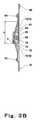
- Fig. 3B is a schematic view showing a state where the cell stack 100 of the fuel cell is assembled (fastened).
- the first band member engagement portion 61 is hatched.
- an engagement portion forming section 63 and an engagement portion forming section 73 are provided at the end of the first band member 60 and at the end of the second band member 70, respectively so as to protrude along the surfaces (in a vertical direction) of the first and second band members 60 and 70.
- the engagement portion forming sections 63 and 73 form the first band member engagement portion 61, the second band member engagement portion 62, the third band member engagement potion 71 and the fourth band member engagement portion 72.
- the engagement portion forming sections 63 and 73 are each folded back to form a tubular shape.
- the tip end portion of the engagement portion forming section 63 and the base end portion of the engagement portion forming section 63 are welded and fastened to each other by screws 64, while the tip end portion of the engagement portion forming section 73 and the base end portion of the engagement portion forming section 73 are welded and fastened to each other by screws 74.
- the first band member engagement portion 61 protrudes from one end of the first band member 60 in one direction (in this embodiment, downward) in a direction in which cells 10 are stacked, and the second band member engagement portion 62 protrudes downward from the other end of the first band member 60.
- the third band member engagement portion 71 protrudes from one end of the second band member 70 in the other direction (in this embodiment, upward) in the direction in which cells 10 are stacked, and the fourth band member engagement portion 72 protrudes upward from the other end of the second band member 70.
- the third band member engagement portion 71 is disposed such that the third band member engagement portion 71 and the second band member engagement portion 62 are aligned when viewed from a direction which is perpendicular to the direction in which the cells 10 are stacked and extend parallel to a pair of side surfaces of the cell stack structure 20.
- the fourth band member engagement portion 72 is disposed such that the fourth band member engagement portion 72 and the first band member engagement portion 61 are aligned when viewed from the direction which is perpendicular to the direction in which the cells 10 are stacked and extend parallel to the pair of side surfaces of the cell stack structure 20.
- the phrase "the direction which is perpendicular to the direction in which the cells 10 are stacked and extend parallel to the pair of side surfaces of the cell stack structure 20" means a direction in which a long side of the side surface of the cells 10 which is covered with the first band member 60 or the second band member 70 extends (hereinafter referred to as the direction in which the long side of the side surface of the cells 10 extends).
- the first band member engagement portion 61 and the second band member engagement portion 62 having the above structure are provided with insertion holes (tubular inner spaces) 65, respectively extending in the direction perpendicular to the direction (in this embodiment, vertical direction) in which the cells 10 are stacked.
- the third band member engagement portion 71 and the fourth band member engagement portion 72 are provided with insertion holes (tubular inner spaces) 75, respectively extending in the direction perpendicular to the direction (in this embodiment, vertical direction) in which the cells 10 are stacked.
- the insertion holes 65 and the insertion holes 75 extend along the side surface of the cells 10 (to be precise, the long side of the side surface of the cells 10).
- the insertion hole 65 of the first band member engagement portion 61 and the insertion hole 75 of the fourth band member engagement portion 72 are arranged in the direction perpendicular to the direction in which the cells 10 are stacked.
- the insertion hole 65 of the second band member engagement portion 62 and the insertion hole 75 of the third band member engagement portion 71 are arranged in the direction perpendicular to the direction in which the cells 10 are stacked.
- the insertion hole 65 of the first band member engagement portion 61 and the insertion hole 75 of the fourth band member engagement portion 72 are arranged in the direction which is perpendicular to the direction in which the cells 10 are stacked and is parallel to the pair of side surfaces of the cell stack structure 20.
- the insertion hole 65 of the second band member engagement portion 62 and the insertion hole 75 of the third band member engagement portion 71 are arranged in the direction which is perpendicular to the direction in which the cells 10 are stacked and is parallel to the pair of side surfaces of the cell stack structure 20.
- the insertion hole 65 of the first band member engagement portion 61 and the insertion hole 75 of the fourth band member engagement portion 72 are arranged so as to overlap or align with each other when viewed from the direction of the long side of the side surface of the cells 10.
- the insertion hole 65 of the second band member engagement portion 62 and the insertion hole 75 of the third band member engagement portion 71 are arranged so as to overlap or align with each other when viewed from the direction of the long side of the side surface of the cells 10.
- the phrase "the insertion hole 65 and the insertion hole 75 are arranged in the direction perpendicular to the direction in which the cells 10 are stacked or arranged in the direction which is perpendicular to the direction in which the cells 10 are stacked and is parallel to the pair of side surfaces of the cell stack structure 20" is meant to include that a part of the insertion hole 65 overlaps a part of the insertion hole 75 when viewed from the direction in which the long side of the side surface of the cells 10 covered with the first band member 60 or the second band member 70 extends, as well as that the insertion hole 65 and the insertion hole 75 are arranged so as to overlap or align with each other, when viewed from the direction in which the long side of the side surface of the cells 10 covered with the first band member 60 or the second band member 70 extends.
- the first band member engagement portion 61 and the third band member engagement portion 71 form a first band engagement portion, while the second band member engagement portion 62 and the fourth band member engagement portion 72 form a second band engagement portion.
- the insertion hole 65 of the first band member engagement portion 61 and the insertion hole 75 of the third band member engagement portion 71 form a first insertion hole, while the insertion hole 65 of the second band member engagement portion 62 and the insertion hole 75 of the fourth band member engagement portion 72 form a second insertion hole.
- the first band member engagement portion 61 of the first band member 60 is formed so as to overlap the second band member engagement portion 62 of the first band member 60, when viewed from the direction which is perpendicular to the direction in which the cells 10 are stacked.
- the third band member engagement portion 71 of the second band member 70 is formed so as to overlap the fourth band member engagement portion 72 of the second band member 70, when viewed from the direction which is perpendicular to the direction in which the cells 10 are stacked.
- the first band member engagement portion 61 of the first band member 60 and the second band member engagement portion 62 of the first band member 60 are formed symmetrically with respect to the cell stack body 50 sandwiched therebetween.
- the third band member engagement portion 71 of the second band member 70 and the fourth band member engagement portion 72 of the second band member 70 are formed symmetrically with respect to the cell stack body 50 sandwiched therebetween.
- the first member engagement portion 61 of the first band member 60 and the fourth band member engagement portion 72 of the second member 70 are arranged at substantially the center of the side surface of the cell stack structure 20
- the second member engagement portion 62 of the first band member 60 and the third band member engagement portion 71 of the second band member 70 are arranged at substantially the center of the side surface of the cell stack structure 20.
- the first band member engagement portion 61 of the first band member 60 and the fourth band member engagement portion 72 of the second band member 60 are formed not to overlap, when viewed from the direction in which the cells 10 are stacked, and the second band member engagement portion 62 ofthe first band member 60 and the third band member engagement portion 71 of the second band member 70 are formed not to overlap, when viewed from the direction in which the cells 10 are stacked.
- the width of the first band member 60 and the width of the second band member 70 are desirably larger than the width for covering power generation sections (cathode and anode electrode sections) of the cells 10. This makes it possible to evenly press the power generation sections of the cells 10.
- the width of the first band member 60 and the width of the second band member 70 are desirably equal to or larger than the width of the end plates 34 as described later. This makes it possible to cover the entire end surfaces of the end plates 34 and evenly press the same. Thereby, stiffness of the end plate 34 need not be high and the material may be selected flexibly.
- the first band member engagement portion 61 of the first band member 60 and the fourth band member engagement portion 72 of the second band member 70 are formed such that a length b in a long axis direction (direction in which the cells 10 are stacked) is not less than twice as large as a length a in a short axis direction (thickness direction of the first band member 60 and the second band member 70), when viewed from the thickness direction of the first band member 60 and the second band member 70.
- the engagement pin 90 can be easily inserted into the first band member engagement portion 61 of the first band member 60 and the fourth band member engagement portion 72 of the second band member 70.
- the engagement pin 90 is inserted into the first band member engagement portion 61 of the first band member 60 and the fourth band member engagement portion 72 of the second band member 70 such that the inner surface of the first band member engagement portion 61 and the inner surface of the fourth band member engagement portion 72 are engaged with the peripheral surface of the engagement pin 90.
- the half of the peripheral surface of the engagement pin 90 is configured to contact each of the inner surface of the first band member engagement portion 61 and the inner surface of the fourth band member engagement portion 71.
- the engagement pin 90, the first band member engagement portion 61 and the fourth band member engagement portion 72 are applied with a force from all directions and thereby fixed, increasing a force against a vibration or an impact applied from outside.
- a large protruding portion is unnecessary. This reduces a space in which the cell stack 100 of the fuel cell is installed or the surface area of the cell stack 100. By reducing the surface area of the cell stack 100 of the fuel cell, the heat radiation amount of the cell stack 100 can be reduced.
- the cell stack 100 can be used as an electric power supply of a cogeneration system which has a high heat recovery property
- a contact resistance between adjacent cells 10 and a contact resistance between the separator and the MEA forming the cell 10 increase due to a large or small fastening load, an uneven fastening load, etc, which may sometimes result in degraded cell performance.
- the polymer electrolyte fuel cell disclosed in Patent document 2 for example, there is a distance between a surface (band) generating a tension and a fulcrum point (engagement portion). For this reason, there is a chance that the engagement portion is deformed due to the tension of the band. The extent of such deformation depends greatly on a variation in stiffness of the engagement portion, a variation in the tension of the band, etc. As a result, the polymer electrolyte fuel cell disclosed in Patent document 2 is incapable of obtaining a stable fastening load.
- the fulcrum point (engagement pin 90) is positioned on the surface generating a tension (surface including the center lines 101A and 101B and being perpendicular to the stacking direction) so that the deformation ofthe engagement portion forming sections 63 and 73 is suppressed. Since the surface generating a tension and the fulcrum point are located on substantially the same plane, the cell stack 100 of the fuel cell can substantially suppress variations in the fastening load due to the deformation.
- the tip end portion and the base end portion of the engagement portion forming section 63 are welded and fastened to each other using the screws 64 and the tip end portion and the base end portion of the engagement portion forming section 73 are welded and fastened to each other using the screws 74, they may alternatively be joined to each other only by welding, only by the screws or by the bonding agent, so long as the engagement portion forming section 63 and the engagement portion forming section 73 are able to have a stiffness sufficient to withstand a fastening pressure.
- the engagement pin 90 has a circular cross-section, its shape is not so limited provided that its peripheral surface has a circular-arc portion.
- the engagement pin 90 may have a cross-section of an oval shape or an elongate-circle shape.
- the cell stack body 50 includes a cell stack structure 20 including plural plate-shaped cells (unit cells) 10 which are stacked, a pair of current collectors 31, a pair of insulating plates 32, an elastic member 33, and a pair of end plates 34 sandwiching these members therebetween.
- the cell stack body 50 has a fuel gas supply manifold 51, a fuel gas exhaust manifold (not shown), an oxidizing gas supply manifold 52, an oxidizing gas exhaust manifold (not shown), a cooling medium supply manifold 53, and a cooling medium discharge manifold (not shown), which are formed to penetrate through the cell stack body 50.
- Each manifold is provided with a connecting member 202 for connecting the pipe 201 to the cell stack body 50 (cell stack 100 of the fuel cell).
- Each cell 10 includes a MEA (membrane-electrode-assembly) consisting of a polymer electrolyte membrane, an anode and cathode disposed on both surfaces thereof, gaskets, and a pair of separators. By contact between the separators of adjacent cells 10, all of the cells 10 are electrically connected in series. By stacking the cells 10 having the above structure in a thickness direction thereof, the cell stack structure 20 is formed.
- MEA membrane-electrode-assembly
- the pair of current collectors 31 are disposed at the both ends of the cell stack structure 20 in the direction in which the cells 10 are stacked.
- Terminal members 31 a are provided on the side surfaces of the current collectors 31.
- Electric wires (not shown) are connected to the terminal members 31a.
- an electric power generated in the respective cells 10 can be output to outside through the terminal members 31a.
- the current collectors 31 are made of a material which is gas-impermeable and electrically conductive.
- the current collectors 31 may be made of dense carbon or metal such as, for example, copper.
- the pair of insulating plates 32 are disposed outside the current collectors 31 of the cell stack structure 20 such that they are respectively in contact with the main surfaces of the current collectors 31. In other words, the pair of insulating plates 32 sandwich and retain a stack of the cell stack structure 20 and the current collectors 31.
- the insulating plates 32 may be made of an insulating material such as rubber or plastic.
- the plate-shaped elastic member 33 is disposed under the insulating plate 32 located at the lower side of the pair of insulating plates 32.
- the elastic member 33 serves to apply a pressing force in the stacking direction to the stack including the cell stack structure 20, the current collectors 31, and others.
- a fastening pressure is applied to the fastener band 80.
- a sheet made of rubber such as fluorine-containing rubber or EPDM may be utilized as the elastic member 33.
- the pair of end plates 34 are disposed at the both ends of the stack including the cell stack structure 20, the current collectors 31, and others such that they are in contact with the main surface of the insulating plate 32 or the main surface of the elastic member 33.
- the end plates 34 serve to apply the fastening force of the fastener band 80 to the cell stack structure 20, the current collectors 31, and others with an even surface pressure.
- the end plates 34 are formed using a stiff material such as, hard plastic or steel, to prevent deformation due to the fastening structure.
- the size of the main surfaces of the end plates 34 is preferably set slightly larger than the size of the cells 10, the main surfaces of the current collectors 31, and others.
- the pair of sides of the main surfaces of the end plates 34, which are in contact with the fastener band 80, are preferably chamfered so that the chamfered portions have a smaller thickness than the center portions.
- the fastener band 80 extends between the pair of end plates 34 to be apart from the side surfaces(i.e., not in contact) of the cell stack structure 20 and the current collectors 31. This makes it possible to prevent a short circuit between the cell stack structure 20 and the current collectors 31 which would otherwise occur because of the fastener band 80. In addition, this makes it possible to prevent the fastening pressure from the fastener band 80 being applied unevenly with respect to the main surfaces of the end plates 3. As a result, the anode and the cathode forming the MEA of each cell 10 can contact the polymer electrolyte membrane of the MEA with an even surface pressure.
- the end plate 34 is placed on the bottom surface of the second band member 70 having a U-shape, and the elastic member 33, the insulating plate 32 and the current collector 31 are placed thereon. Then, the plural cells 10 are stacked on the main surface ofthe current collector 31, forming the cell stack structure 20. Then, on the main surface of the cell 10 of the cell stack structure 20, the current collector 31, the insulating plate 32 and the end plate 34 are placed, and the first band member 60 having a U-shape is placed so as to cover the main surface of the end plate 34.
- the cell stack body 50 is formed, and the first band member 60 and second band member 70 are placed so as to surround the periphery of the cell stack body 50 and so as to cover a pair of end surfaces of the cell stack body 50 (main surfaces of the end plates 34) and a pair of opposing side surfaces of the cell stack body 50.
- the first band member 60, the cell stack body 50, and the second band member 70 are pressed together so as to have a specified dimension in the stacking direction.
- the pair of engagement pins 90 are inserted into the first band member engagement portion 61 of the first band member 60 and the fourth band member engagement portion 72 of the second band member 70, and into the second band member engagement portion 62 of the first band member 60 and the third band member engagement portion 71 of the second band member 70 (see Fig. 3B ).
- a predetermined load which is larger than the fastening load of the cell stack 100 of the fuel cell is applied to the portions of the first band member 60 and the second band member 70, which cover the pair of end surfaces (main surfaces of the end plates 34) of the cell stack body 50. Then, the engagement pin 90 is inserted into the insertion hole 65 of the first band member engagement portion 61 and into the insertion hole 75 of the fourth band member engagement portion 72, and the engagement pin 90 is inserted into the insertion hole 65 of the second band member engagement portion 62 and into the insertion hole 75 of the third band member engagement portion 71.
- the first band member 60 and the second band member 70 are pushed in the direction in which the cells 10 are stacked by the elastic force of the elastic member 33 to cause the first band member engagement portion 61 and the fourth band member engagement portion 72 to be deformed by a tensile force to cause the center line 101A to be oriented in the direction (i.e., vertical direction) along the center line of the first band member 60 and adhere to the engagement pin 90, and to cause the second band member engagement portion 62 and the third band member engagement portion 71 to be deformed by a tensile force to cause the center line 101B to be oriented in the direction (i.e., vertical direction) along the center line of the second band member 70 and adhere to the engagement pin 90.
- the cell stack 100 of the fuel cell is fastened (see Fig. 3A ).
- the engagement pin 90 is engaged with the inner surface of the insertion hole 65 of the first band member engagement portion 61 and the inner surface of the insertion hole 75 of the fourth band member engagement portion 72, and the engagement pin 90 is engaged with the inner surface of the insertion hole 65 of the second band member engagement portion 62 and the inner surface of the insertion hole 75 of the third band member engagement portion 71, causing the first band member 60 and the second band member 70 to be indirectly engaged with each other via the engagement pins 90.
- the cell stack body 50 is fastened by the fastener band 80.
- the cell stack 100 of the fuel cell according to Embodiment 1 by inserting the engagement pin 90 into the first band member engagement portion 61 of the first band member 60 and the fourth band member engagement portion 72 of the second band member 70, and by inserting the engagement pin 90 into the second band member engagement portion 62 of the first band member 60 and the third band member engagement portion 71 of the second band member 70, the cell stack 100 of the fuel cell can be fastened.
- assembling of the cell stack 100 is accomplished with fewer components and fewer steps.
- the cell stack 100 of the fuel cell can be made compact.
- the surface area of the cell stack 100 of the fuel cell can be reduced, and its heat radiation amount can be reduced.
- the length b of the first band member engagement portion 61, the second band member engagement portion 62, the third band member engagement portion 71 and the fourth band member engagement portion 72 in the long axis direction is set to a length which is not less than twice as large as the length a in the short axis direction, it is possible to ensure a sufficient clearance required to insert the engagement pin 90. As a result, the cell stack 100 of the fuel cell can be easily assembled.
- the engagement pins 90 are inserted in the direction perpendicular to the direction in which the fastening load is applied to the cell stack 100 and the cells 10 are stacked, it is possible to avoid that the engagement pins 90 are disengaged due to a vibration or an impact. Furthermore, since the first band member engagement portion 61, the second band member engagement portion 62, the third band member engagement portion 71 and the fourth band member engagement portion 72 are deformed when fastening the cell stack 100 of the fuel cell, the inner surfaces of these engagement portions adhere to and are fixed to the peripheral surfaces of the engagement pins 90. As a result, vibration proof property and impact resistance of the cell stack 100 of the fuel cell are improved.
- first band member engagement portion 61, the second band member engagement portion 62, the third band member engagement portion 71 and the fourth band member engagement portion 72 are located at substantially the centers of the side surfaces of the cell stack structure 20 (cell stack body 50), it is possible to suppress external forces such as a vibration and an impact concentrating in a localized region.
- Fig. 4 is a table showing the result of simulations conducted to research whether or not a local stress is generated on the end plates 34 and the like depending on the positions of the first band engagement portion and the second band engagement portion in the cell stack 100 of the fuel cell.
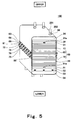
- Fig. 5 is a perspective view schematically showing a configuration of a cell stack of a fuel cell according to Embodiment 2 of the present invention.
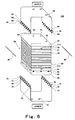
- Fig. 6 is an exploded schematic view of the cell stack of the fuel cell of Fig. 5 .
- the upper and lower sides of the cell stack of the fuel cell are expressed as the upper and lower sides in these Figures.
- the cell stack 100 of the fuel cell according to Embodiment 2 of the present invention has a structure which is basically identical to that of the cell stack 100 of the fuel cell according to Embodiment 1, except for the structures of the elastic member 33 and the first band member engagement portion 61, the second band member engagement portion 62, the third band member engagement portion 71 and the fourth band member engagement portion 72.
- the elastic member 33 is formed by compressive springs.
- the first band member engagement portion 61, the second band member engagement portion 62, the third band member engagement portion 71 and the fourth band member engagement portion 72 have plural (in this embodiment, seven) engagement units 66 and plural (seven) engagement units 76.
- the engagement units 66 have a comb shape and the engagement units 76 have a comb shape.
- the engagement units 66 protrude from the ends of the first band member 60 along the surface thereof (in this embodiment, vertical direction) and the engagement units 76 protrude from the ends of the second band member 70 along the surface thereof (in this embodiment, vertical direction).
- An insertion hole 65 and an insertion hole 75 are defined by an inner space of the engagement unit 66 and an inner space of the engagement unit 76, respectively.
- the engagement units 66 provided at the first band member engagement portion 61 of the first band member 60 and the engagement units 76 provided at the fourth band member engagement portion 72 ofthe second band member 70 are provided such that they are not in contact with each other.
- the engagement units 66 provided at the second band member engagement portion 62 of the first band member 60 and the engagement units 76 provided at the third band member engagement portion 71 of the second band member 70 are provided such that they are not in contact with each other.
- the cell stack 100 of the fuel cell of Embodiment 2 configured as described above is able to achieve the same advantage as that of the cell stack 100 of the fuel cell of Embodiment 1.
- Fig. 7 is a perspective view schematically showing a configuration of a cell stack of a fuel cell according to Embodiment 3 of the present invention.
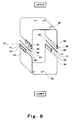
- Fig. 8 is a perspective view schematically showing a configuration of a first band member and a second band member forming the cell stack of the fuel cell of Fig. 7 .
- the upper and lower sides of the cell stack of the fuel cell are expressed as the upper and lower sides in these Figures.
- the upper and lower sides of the first band member and the second band member are expressed as the upper and lower sides in these Figures.
- the cell stack 100 of the fuel cell according to Embodiment 3 of the present invention has a structure which is basically identical to that of the cell stack 100 of the fuel cell according to Embodiment 1 except that the first band member engagement portion 61, the second band member engagement portion 62, the third band member engagement portion 71 and the fourth band member engagement portion 72 are not formed by the engagement portion forming sections 63 and 73, but by separate members.
- the first band member engagement portion 61, the second band member engagement portion 62, the third band member engagement portion 71 and the fourth band member engagement portion 72 are formed in such a manner that plate members 67 and plate members 77 are folded back to form tubular insertion holes 65 and 75 and one ends thereof are fastened by welding.
- the plate members 67 are bonded to the first band member 60 using screws 64 and by welding, and the plate members 77 are bonded to the second band member 70 by screws 74 and by welding.
- the plate members 67 and 77 are desirably made of a material which can withstand a fastening pressure, and may be made of, for example SUS or the like.
- the first band member 60 is cut at the portions of the both ends where the plate members 67 are not provided and the second band member 70 is cut at the portions of the both ends where the plate members 77 are not provided, to prevent contact with the first band member engagement portion 61, the second band member engagement portion 62, the third band member engagement portion 71 and the fourth band member engagement portion 72, when fastening the cell stack 100 of the fuel cell.
- the cell stack 100 of the fuel cell of Embodiment 3 configured as described above is able to achieve the same advantage as that of the cell stack 100 of the fuel cell of Embodiment 1.
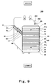
- Fig. 9 is a perspective view schematically showing a configuration of a cell stack of a fuel cell according to Embodiment 4 of the present invention.
- the upper and lower sides of the cell stack of the fuel cell are expressed as the upper and lower sides in the Figure.
- the cell stack 100 of the fuel cell according to Embodiment 4 of the present invention has a structure which is basically identical to that of the cell stack 100 of the fuel cell according to Embodiment 1, except that the first band member engagement portion 61 of the first band member 60 is formed not to overlap the second band member engagement portion 62 of the first band member 60, when viewed from the direction perpendicular to the direction in which the cells 10 are stacked and the third band member engagement portion 71 of the second band member 70 is formed not to overlap the fourth band member engagement portion 72 of the second band member 70, when viewed from the direction perpendicular to the direction in which the cells 10 are stacked.
- the first band member engagement portion 61 of the first band member 60 and the fourth band member engagement portion 72 of the second band member 70, and the second band member engagement portion 62 of the first band member 60 and the third band member engagement portion 71 of the second band member 70 are desirably located on the side surfaces of the cell stack structure 20 and not on the side surfaces of the current collectors 31, the insulating plates 32, the elastic member 33, and the end plates 34.
- the cell stack 100 of the fuel cell of Embodiment 4 configured as described above is able to achieve the same advantage as that of the cell stack 100 of the fuel cell of Embodiment 1.
- Fig. 10 is a perspective view schematically showing a configuration of a cell stack of a fuel cell according to Embodiment 5 of the present invention.
- Fig. 11 is perspective view schematically showing a configuration of a fastener band of the cell stack of the fuel cell of Fig. 10 .
- the upper and lower sides of the cell stack of the fuel cell are expressed as the upper and lower sides in these Figures.
- the upper and lower sides of the first band member and the second band member are expressed as the upper and lower sides in these Figures.
- the cell stack 100 of the fuel cell according to Embodiment 5 of the present invention has a structure which is basically identical to that of the cell stack 100 of the fuel cell according to Embodiment 1, except that the fastener band 80 is formed by a single member. Since the fastener band 80 is formed by a single member, a first band engagement portion 68 and a second band engagement portion 78 are provided at the both ends of the fastener band 80.
- the fastener band 80 is formed such that a band-like member is bent to form a tubular shape so as to surround the cell stack body 50, and the portion of the fastener band 80 which covers the upper surface of the cell stack body 50 (hereinafter referred to as the upper surface of the fastener band 80) is formed to be tilted obliquely upward with respect to a horizontal direction. Since the first band engagement portion 68 and the second band engagement portion 78 have the same structure as the first band member engagement portion 61 of the first band member 60, the fourth band member engagement portion 72 of the second band member 70 and others, detailed description thereof is omitted.
- the fastener band 80 and the cell stack body 50 are pressed in such a manner that the upper surface of the fastener band 80 and the portion of the fastener band 80 which covers the lower surface of the cell stack body 50 (lower surface of the fastener band 80) are pressed using the presser unit (e.g., flat press machine) until the upper surface of the fastener band 80 is pressed down to be tilted slightly downward with respect to a horizontal direction.
- the presser unit e.g., flat press machine
- the insertion hole 65 of the first band engagement portion 68 and the insertion hole 75 of the second band engagement portion 78 overlap each other when viewed from the direction perpendicular to the direction in which the cells 10 are stacked, and the engagement pin 90 can be inserted into the insertion hole 65 and the insertion hole 75.
- the pressing force applied by the presser unit is released, so that the fastener band 80 and the cell stack body 50 are pushed back up to a position where the upper surface of the fastener band 80 is horizontal, because of the elastic force of the elastic member 33.
- the first band engagement portion 68 and the second band engagement portion 78 are deformed due to their tensile forces and are allowed to adhere to the engagement pin 90.
- the cell stack 100 of the fuel cell is fastened.
- the cell stack 100 of the fuel cell of Embodiment 5 configured as described above is able to achieve the same advantage as that of the cell stack 100 of the fuel cell of Embodiment 1.
- Fig. 12 is a perspective view schematically showing a configuration of a cell stack of a fuel cell according to Embodiment 6 of the present invention.
- the upper and lower sides of the cell stack of the fuel cell are expressed as the upper and lower sides in the Figure.
- the cell stack 100 of the fuel cell according to Embodiment 6 of the present invention has a structure which is basically identical to that of the cell stack 100 of the fuel cell according to Embodiment 1, except that the cell stack 100 of the fuel cell is fastened using plural (four) thinned and elongated fastener bands 80.
- the cell stack 100 of the fuel cell of Embodiment 6 configured as described above is able to achieve the same advantage as that of the cell stack 100 of the fuel cell of Embodiment 1.
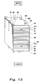
- Fig. 13 is a perspective view schematically showing a configuration of a cell stack of a fuel cell according to Embodiment 7 of the present invention.
- the upper and lower sides of the cell stack of the fuel cell are expressed as the upper and lower sides in the Figure.
- the cell stack 100 ofthe fuel cell according to Embodiment 7 of the present invention has a structure which is basically identical to that of the cell stack 100 of the fuel cell according to Embodiment 5, except that the opening (both ends) of the fastener band 80 is formed to be located at a corner portion formed between the side surface and the upper surface of the cell stack body 50, and the first band engagement portion 68 and the second band engagement portion 78 are different in shape.
- each first band engagement portion 68 is formed by a columnar member and is provided on the upper surface of the fastener band 80 such that its tip end portion protrudes from the end of the upper surface of the fastener band 80.
- a through-hole is formed at the tip end portion of each first band engagement portion 68 so as to extend along the direction in which the cells 10 are stacked.
- each first band engagement portion 68 is bonded to the upper surface of the fastener band 80 by welding.
- Each second band engagement portion 78 is formed by a tubular member and is bonded to the side surface of the fastener band 80.
- the peripheral surfaces of the engagement pins 90 are configured to contact the inner surfaces of the first band engagement portions 68 and the inner surfaces of the second band engagement portions 78 by the elastic force in the upper surface of the fastener band 80 and the elastic force in the side surface of the fastener band 80 on which the second band engagement portions 78 are provided, which are applied in the direction to increase the opening of the fastener band 80, to be precise, the elastic force in the upper surface of the fastener band 80 in an upward direction, and the elastic force in the side surface of the fastener band 80 on which the second band engagement portions 78 are provided, which is applied in the direction from the side surface on which the second band engagement portions 78 are not provided toward the side surface on which the second band engagement portions 78 are provided.
- the engagement pins 90, the first band engagement portions 68 and the second band engagement portions 78 are fixed, and the cell stack 100 of the fuel cell is fastened.
- the cell stack 100 of the fuel cell of Embodiment 7 configured as described above is able to achieve the same advantage as that of the cell stack 100 of the fuel cell of Embodiment 1.
- a cell stack of a fuel cell and a method of fastening the cell stack of the fuel cell, of the present invention are useful in technical fields of fuel cells, in that the cell stack of fuel cells can be made contact, its surface area can be reduced, and the cell stack can be assembled with fewer components and fewer assembly steps without degrading performance of the cell stack.
Landscapes
- Life Sciences & Earth Sciences (AREA)
- Engineering & Computer Science (AREA)
- Manufacturing & Machinery (AREA)
- Sustainable Development (AREA)
- Sustainable Energy (AREA)
- Chemical & Material Sciences (AREA)
- Chemical Kinetics & Catalysis (AREA)
- Electrochemistry (AREA)
- General Chemical & Material Sciences (AREA)
- Fuel Cell (AREA)
Abstract
Description
- The present invention relates to a cell stack of a fuel cell and a method of fastening the cell stack of the fuel cell. More particularly, the present invention relates to a cell stack of a fuel cell including a cell stack body fastened using a fastener band, and a method of fastening the cell stack of the fuel cell.
- A cell stack of a typical fuel cell is formed by arranging current collectors, insulating plates and end plates in this order at both ends of a cell stack structure including plural cells (unit cells) stacked, and by fastening this stack structure by fastener rods (bolts and nuts) in a direction in which the cells are stacked (see e.g., patent literature 1). In a fastening structure using the fastener rods (bolts and nuts), since the head portions and tip end portions of the bolts and the nuts protrude from the surfaces of the end plates, the size of the fuel cell increases.
- Under the circumstances, various techniques for reducing the size of the fuel cell by reducing the size of the fastening structure of the cell stack have been developed. For example, techniques for fastening the cell stack using a thin fastener band are disclosed (see e.g., patent literature 2 and patent literature 3). In the fuel cells disclosed in patent literature 2 and patent literature 3 using the fastener band to fasten the cell stack structure, the end plates and others, the fastener band does not protrude substantially from the surfaces of the end plates. Therefore, the size of the fuel cell can be reduced.
-
- Patent literature 1: Japanese Laid-Open Patent Application Publication No.
2007-59087 - Patent literature 2: Japanese Laid-Open Patent Application Publication No.
2007-67902 - Patent literature 3: Translated Japanese Application Publication No.
2001-504632 - However, in the polymer electrolyte fuel cell disclosed in patent literature 2, since a connecting portion of the band is fastened by bolts and nuts, the protruding portions of at least the bolts and the nuts are required as the connecting portion, thereby increasing a weight and a volume of the fuel cell. As a surface area of the fuel cell increases, a heat radiation amount of the fuel cell increases. For example, when the fuel cell is used as an electric power supply in a cogeneration system and therefore heat recovery is necessary, performance of the fuel cell degrades. In addition, the number of steps for fastening the bolts and the nuts and the number of components increases, reducing assembling efficiency.
- In the fuel cell stack structure disclosed in patent literature 3, since an annular band formed by welding both ends of a band-like member, which is made of metal or the like is used, the cell stack structure is subjected to an unnecessary load or an excess load such as high-temperature heat, in the assembly process. When the band is welded after assembling, heat applied to a weld portion is transmitted to a resin material which is low in heat resistance, such as a gasket or a polymer electrolyte membrane of the cell, degrading durability of the fuel cell.
- Furthermore, in the above mentioned conventional fastening method, since it is necessary to adjust each of the plural fastener rods or each of the plural bands, the manufacturing steps increases in number, which is undesirable.
- The present invention is directed to solving the above described problem, and an object of the present invention is to provide a cell stack of a fuel cell which enables a fuel cell to be compact and have a smaller surface area, and which is assembled with fewer components and fewer steps, without degrading performance of the cell stack in its assembled state, and a method of fastening the cell stack of the fuel cell.
- To achieve the above described objective, a cell stack of a fuel cell of the present invention, comprises a cell stack body including a cell stack structure including plural cells stacked; an elastic member disposed at an end ofthe cell stack structure in a direction in which the cells are stacked together; and a pair of end plates sandwiching the cell stack structure and the elastic member; and a fastener band extending to surround the cell stack body and so as to cover a pair of end surfaces and a pair of opposing side surfaces of the cell stack body, the fastener band including a first band engagement portion and a second band engagement portion; wherein the cell stack body is fastened by the fastener band by direct or indirect engagement between the first band engagement portion and the second band engagement portion.
- In such a configuration, the cell stack ofthe fuel cell can be made compact and its surface area can be reduced. In addition, the cell stack can be assembled with fewer components and fewer steps without degrading performance of the cell stack in its assembled state.
- In the cell stack of the fuel cell of the present invention, the fastener band may be disposed such that the first band engagement portion and the second band engagement portion are located on the side surface of the cell stack structure.
- The cell stack of the fuel cell of the present invention may further comprise an engagement pin. The first band engagement portion and the second band engagement portion may have a first insertion hole and a second insertion hole, respectively; and the engagement pin may be inserted into the first insertion hole of the first band engagement portion and the second insertion hole of the second band engagement portion to cause the first band engagement portion and the second band engagement portion to be engaged with each other via the engagement pin.
- In the cell stack of the fuel cell of the present invention, the first band engagement portion and the second band engagement portion may be provided such that the first insertion hole and the second insertion hole are arranged in a direction perpendicular to the direction in which the cells are stacked.
- In the cell stack of the fuel cell of the present invention, the first band engagement portion may protrude from one end of the fastener band in one direction of the direction in which the cells are stacked. The second band engagement portion may protrude from the other end of the fastener band in the other direction of the direction in which the cells are stacked, the other direction being opposite to the one direction. The first band engagement portion and the second band engagement portion may be provided such that the first insertion hole of the first band engagement portion and the second insertion hole of the second band engagement portion extend along a side surface of the cells.
- In the cell stack of the fuel cell of the present invention, the second band engagement portion may be provided such that the second band engagement portion and the first band engagement portion are arranged in a direction perpendicular to the direction in which the cells are stacked and parallel to the pair of side surfaces of the cell stack structure. The first band engagement portion and the second band engagement portion may be provided such that the first and second insertion holes are arranged in the direction which is perpendicular to the direction in which the cells are stacked and is parallel to the pair of side surfaces of the cell stack structure.
- In the cell stack of the fuel cell of the present invention, the engagement pin may have a peripheral surface having a circular-arc portion. The circular-arc portion of the engagement pin may be engaged with an inner surface of the first band engagement portion which is formed by the first insertion hole and an inner surface of the insertion hole of the second band engagement portion which is formed by the second insertion hole.
- In the cell stack of the fuel cell of the present invention, each of the first band engagement portion and the second band engagement portion may have, at both end portions of the fastener band, respectively, a long axis extending in the direction in which the cells are stacked and a short axis extending in a direction perpendicular to the long axis, and the long axis has a length which is not smaller than a length which is twice as large as a length of the short axis.
- In the cell stack of the fuel cell of the present invention, the first band engagement portion and the second band engagement portion may be deformed by a load applied to fasten the cell stack of the fuel cell.
- In the cell stack of the fuel cell of the present invention, the first band engagement portion and the second band engagement portion may be provided so as not to overlap with each other when viewed from the direction in which the cells are stacked.
- In the cell stack of the fuel cell of the present invention, the first band engagement portion and the second band engagement portion may be provided so as to overlap with each other when viewed from the direction perpendicular to the direction in which the cells are stacked.
- In the cell stack of the fuel cell of the present invention, the first fastener band may include a first band member and a second band member. The first band member may have a first band member engagement portion at one end portion thereof and a second band member engagement portion at the other end portion thereof The second band member may have a third band member engagement portion at one end portion thereof and a fourth band member engagement portion at the other end portion thereof The first band engagement portion may include the first band member engagement portion and the third band member engagement portion, and the second band engagement portion may include the second band member engagement portion and the fourth band member engagement portion. The first band member engagement portion and the fourth band member engagement portion may be directly or indirectly engaged with each other, and the second band member engagement portion and the third band member engagement portion are directly or indirectly engaged with each other, to cause the cell stack body to be fastened by the fastener band.
- In the cell stack of the fuel cell of the present invention, the first band member and the second band member may be configured such that the ends thereof are located at centers of the side surfaces of the cell stack body, respectively.
- In the cell stack of the fuel cell of the present invention, the fastener band may be provided with a hole into which a pipe is inserted to supply or discharge a fluid flowing in the cell stack body.
- A cell stack of a fuel cell of the present invention, comprises a cell stack body including a plurality of cells stacked together to form a cell stack structure; an elastic member disposed at an end of the cell stack structure; a pair of end plates sandwiching the cell stack structure and the elastic member; a fastener band extending so as to surround the cell stack body and to cover a pair of end surfaces and a pair of opposing side surfaces of the cell stack body, the fastener band including a first band engagement portion and a second band engagement portion and an engagement pin configured to engage the first band engagement portion and the second band engagement portion and secure the first band engagement portion and the second band engagement to one another.
- A method of fastening a cell stack of a fuel cell of the present invention comprises: a step (A) for forming a cell stack body including a cell stack structure including plural cells stacked; an elastic member disposed at an end of the cell stack structure in a direction in which the cells are stacked; and a pair of end plates sandwiching the cell stack structure and the elastic member, and disposing a fastener band so as to surround the cell stack body and so as to cover a pair of end surfaces and a pair of opposing side surfaces of the cell stack body, the fastener band having a first band engagement portion and a second band engagement portion; and a step (B) for directly or indirectly engaging the first band engagement portion and the second band engagement portion with each other to fasten the cell stack body by using the fastener band.
- In such a configuration, the cell stack of the fuel cell can be assembled with fewer components and fewer steps without degrading performance of the cell stack in its assembled state.
- In the method of fastening the cell stack of the fuel cell of the present invention, the step (B) may include: a step (B 1) for applying a predetermined load which is larger than a fastening load to portions of the fastener band which cover the pair of end surfaces of the cell stack body, using a presser unit, and inserting the engagement pin into a first insertion hole of the first band engagement portion and a second insertion hole of the second band engagement portion; and a step (B2) for releasing the load applied by the presser unit to engage the engagement pin with an inner surface of the first band engagement portion formed by the first insertion hole, and an inner surface of the second band engagement portion formed by the second insertion hole.
- In such a configuration, the cell stack of the fuel cell can be assembled with fewer components and fewer steps without degrading performance of the cell stack in its assembled state.
- In a cell stack of a fuel cell and a method of fastening the cell stack of the fuel cell, of the present invention, a fuel cell can be made contact, its surface area can be reduced, and the cell stack can be assembled with fewer components and fewer assembly steps without degrading performance ofthe cell stack.
-
- [
Fig. 1] Fig. 1 is a perspective view schematically showing a configuration of a cell stack of a fuel cell according to Embodiment 1 of the present invention. - [
Fig. 2] Fig. 2 is an exploded schematic view of the cell stack of the fuel cell ofFig. 1 . - [
Fig. 3A] Fig. 3A is a cross-sectional view taken along line IIIA-IIIA ofFig. 1 . - [
Fig. 3B] Fig. 3B is a schematic view showing a state where the cell stack of the fuel cell is assembled (fastened). - [
Fig. 4] Fig. 4 is a table showing a result of simulation conducted to determine whether or not a local stress is generated in an end plate or the like, depending on the positions at which a first band engagement portion and a second band engagement portion are provided, in the cell stack of the fuel cell. - [
Fig. 5] Fig. 5 is a perspective view schematically showing a configuration of a cell stack of a fuel cell according to Embodiment 2 of the present invention. - [
Fig. 6] Fig. 6 is an exploded schematic view of the cell stack of the fuel cell ofFig. 5 . - [
Fig. 7] Fig. 7 is a perspective view schematically showing a configuration of a cell stack of a fuel cell according to Embodiment 3 of the present invention. - [
Fig. 8] Fig. 8 is a perspective view schematically showing a configuration of a first band member and a second band member of the cell stack of the fuel cell ofFig. 7 . - [
Fig. 9] Fig. 9 is a perspective view schematically showing a configuration of a cell stack of a fuel cell according to Embodiment 4 of the present invention. - [
Fig. 10] Fig. 10 is a perspective view schematically showing a configuration of a cell stack of a fuel cell according to Embodiment 5 of the present invention. - [
Fig. 11] Fig. 11 is a perspective view schematically showing a configuration of a fastener band of the cell stack of the fuel cell ofFig. 10 . - [
Fig. 12] Fig. 12 is a perspective view schematically showing a configuration of a cell stack of a fuel cell according to Embodiment 6 of the present invention. - [
Fig. 13] Fig. 13 is a perspective view schematically showing a configuration of a cell stack of a fuel cell according to Embodiment 7 of the present invention. - Hereinafter, preferred embodiments of the present invention will be described with reference to the drawings. Throughout the drawings, the same or corresponding components and members are designated by the same reference numerals and repetitive description thereof will be omitted. In the embodiments described below, the present invention is applied to a polymer electrolyte fuel cell (PEFC) but is widely applicable to other kinds of fuel cells such as, but not limited to, solid oxide fuel cell (SOFC) or phosphoric acid fuel cell (PAFC).
-
Fig. 1 is a perspective view schematically showing a configuration of a cell stack of a fuel cell according to Embodiment 1 of the present invention.Fig. 2 is an exploded schematic view of the cell stack of the fuel cell ofFig. 1 . InFigs. 1 and2 , the upper and lower sides of the cell stack of the fuel cell are expressed as the upper and lower sides in these Figures. - As shown in
Figs. 1 and2 , acell stack 100 of a fuel cell includes acell stack body 50 having a rectangular parallelepiped configuration, afastener band 80 including a firstU-shaped band member 60 and a secondU-shaped band member 70, and a pair of engagement pins 90. Thefirst band member 60 and thesecond band member 70 extend so as to surround thecell stack body 50 and so as to cover the upper surface (upper end surface) of thecell stack body 50, the lower surface (lower end surface) of thecell stack body 50, and a pair of opposing side surfaces of thecell stack body 50. Thefirst band member 60 has plural (in this embodiment, three) through-holes 69 on a top surface thereof covering the upper surface of thecell stack body 50. Thesecond band member 70 has plural (in this embodiment, three) through-holes 79 on a bottom surface thereof covering the lower surface of thecell stack body 50.Pipes 201 used for supplying to or discharging from the cell stack 100 (cell stack body 50) of the fuel cell, a fluid such as a fuel gas flowing in thecell stack body 50, are respectively inserted into the through-holes - A first tubular band
member engagement portion 61 and a second tubular bandmember engagement portion 62 are provided at both ends of thefirst band member 60, respectively. Likewise, a third tubular bandmember engagement portion 71 and a fourth tubular bandmember engagement portion 72 are provided at both ends of thesecond band member 70, respectively. - One of the pair of the engagement pins 90 is inserted into the first band
member engagement portion 61 of thefirst band member 60 and the fourth bandmember engagement portion 72 of thesecond band member 70. In the same manner, theother engagement pin 90 is inserted into the second bandmember engagement portion 62 of thefirst band member 60 and the third bandmember engagement portion 71 of thesecond band member 70. Thereby, the first bandmember engagement portion 61 of thefirst band member 60 and the fourth bandmember engagement portion 72 of thesecond band member 70 are engageable with each other via theengagement pin 90, while the second bandmember engagement portion 62 of thefirst band member 60 and the third bandmember engagement portion 71 of thesecond band member 70 are engageable with each other via theengagement pin 90. In other words, the first bandmember engagement portion 61 of thefirst band member 60 and the fourth bandmember engagement portion 72 of thesecond band member 70 are indirectly engageable with each other via theengagement pin 90, while the second bandmember engagement portion 62 of thefirst band member 60 and the third bandmember engagement portion 71 of thesecond band member 70 are indirectly engageable with each other via theengagement pin 90. Thus, when the engagement pins 90 are inserted, thefirst band member 60 and thesecond band member 70 are secured together. - The
first band member 60 and thesecond band member 70 are made of a material which is excellent in tensile strength and anticorrosion, such as, but not limited to, resin (engineering plastic, elastomer, etc), stainless steel (e.g., SUS304), or chrome molybdenum steel. The engagement pins 90 are made of a material such as, but not limited to, chrome molybdenum steel, or stainless steel (e.g., SUS304). - With reference to
Figs. 3A and3B , the structures of the first bandmember engagement portion 61 and the second bandmember engagement portion 62 of thefirst band member 60 and the third bandmember engagement portion 71 and the fourth bandmember engagement portion 72 of thesecond band member 70 will be described in greater detail. Since the first bandmember engagement portion 61 and the second bandmember engagement portion 62 of thefirst band member 60 have the same structure, and the third bandmember engagement portion 71 and the fourth bandmember engagement portion 72 of thesecond band member 70 have the same structure, the first bandmember engagement portion 61 of thefirst band member 60 and the fourth bandmember engagement portion 72 of thesecond band member 70 will be described hereinafter. -
Fig. 3A is a cross-sectional view taken along line IIIA-IIIA ofFig. 1 .
Fig. 3B is a schematic view showing a state where thecell stack 100 of the fuel cell is assembled (fastened). InFigs. 3A and3B , to clearly distinguish between the first bandmember engagement portion 61 of the first andmember 60 and the fourth bandmember engagement portion 72 of thesecond band member 70, the first bandmember engagement portion 61 is hatched. - As shown in
Figs. 1 to 3B , an engagementportion forming section 63 and an engagementportion forming section 73 are provided at the end of thefirst band member 60 and at the end of thesecond band member 70, respectively so as to protrude along the surfaces (in a vertical direction) of the first andsecond band members portion forming sections member engagement portion 61, the second bandmember engagement portion 62, the third bandmember engagement potion 71 and the fourth bandmember engagement portion 72. The engagementportion forming sections portion forming section 63 and the base end portion of the engagementportion forming section 63 are welded and fastened to each other byscrews 64, while the tip end portion of the engagementportion forming section 73 and the base end portion of the engagementportion forming section 73 are welded and fastened to each other byscrews 74. - To be specific, the first band
member engagement portion 61 protrudes from one end of thefirst band member 60 in one direction (in this embodiment, downward) in a direction in whichcells 10 are stacked, and the second bandmember engagement portion 62 protrudes downward from the other end of thefirst band member 60. In the same manner, the third bandmember engagement portion 71 protrudes from one end of thesecond band member 70 in the other direction (in this embodiment, upward) in the direction in whichcells 10 are stacked, and the fourth bandmember engagement portion 72 protrudes upward from the other end of thesecond band member 70. In other words, the third bandmember engagement portion 71 is disposed such that the third bandmember engagement portion 71 and the second bandmember engagement portion 62 are aligned when viewed from a direction which is perpendicular to the direction in which thecells 10 are stacked and extend parallel to a pair of side surfaces of thecell stack structure 20. Likewise, the fourth bandmember engagement portion 72 is disposed such that the fourth bandmember engagement portion 72 and the first bandmember engagement portion 61 are aligned when viewed from the direction which is perpendicular to the direction in which thecells 10 are stacked and extend parallel to the pair of side surfaces of thecell stack structure 20. As used herein, the phrase "the direction which is perpendicular to the direction in which thecells 10 are stacked and extend parallel to the pair of side surfaces of thecell stack structure 20" means a direction in which a long side of the side surface of thecells 10 which is covered with thefirst band member 60 or thesecond band member 70 extends (hereinafter referred to as the direction in which the long side of the side surface of thecells 10 extends). - The first band
member engagement portion 61 and the second bandmember engagement portion 62 having the above structure are provided with insertion holes (tubular inner spaces) 65, respectively extending in the direction perpendicular to the direction (in this embodiment, vertical direction) in which thecells 10 are stacked. In the same manner, the third bandmember engagement portion 71 and the fourth bandmember engagement portion 72 are provided with insertion holes (tubular inner spaces) 75, respectively extending in the direction perpendicular to the direction (in this embodiment, vertical direction) in which thecells 10 are stacked. - To be specific, the insertion holes 65 and the insertion holes 75 extend along the side surface of the cells 10 (to be precise, the long side of the side surface of the cells 10). The
insertion hole 65 of the first bandmember engagement portion 61 and theinsertion hole 75 of the fourth bandmember engagement portion 72 are arranged in the direction perpendicular to the direction in which thecells 10 are stacked. In the same manner, theinsertion hole 65 of the second bandmember engagement portion 62 and theinsertion hole 75 of the third bandmember engagement portion 71 are arranged in the direction perpendicular to the direction in which thecells 10 are stacked. To be more specific, theinsertion hole 65 of the first bandmember engagement portion 61 and theinsertion hole 75 of the fourth bandmember engagement portion 72 are arranged in the direction which is perpendicular to the direction in which thecells 10 are stacked and is parallel to the pair of side surfaces of thecell stack structure 20. In the same manner, theinsertion hole 65 of the second bandmember engagement portion 62 and theinsertion hole 75 of the third bandmember engagement portion 71 are arranged in the direction which is perpendicular to the direction in which thecells 10 are stacked and is parallel to the pair of side surfaces of thecell stack structure 20. - In other words, the
insertion hole 65 of the first bandmember engagement portion 61 and theinsertion hole 75 of the fourth bandmember engagement portion 72 are arranged so as to overlap or align with each other when viewed from the direction of the long side of the side surface of thecells 10. Theinsertion hole 65 of the second bandmember engagement portion 62 and theinsertion hole 75 of the third bandmember engagement portion 71 are arranged so as to overlap or align with each other when viewed from the direction of the long side of the side surface of thecells 10. As used herein, the phrase "theinsertion hole 65 and theinsertion hole 75 are arranged in the direction perpendicular to the direction in which thecells 10 are stacked or arranged in the direction which is perpendicular to the direction in which thecells 10 are stacked and is parallel to the pair of side surfaces of thecell stack structure 20" is meant to include that a part of theinsertion hole 65 overlaps a part of theinsertion hole 75 when viewed from the direction in which the long side of the side surface of thecells 10 covered with thefirst band member 60 or thesecond band member 70 extends, as well as that theinsertion hole 65 and theinsertion hole 75 are arranged so as to overlap or align with each other, when viewed from the direction in which the long side of the side surface of thecells 10 covered with thefirst band member 60 or thesecond band member 70 extends. - The first band
member engagement portion 61 and the third bandmember engagement portion 71 form a first band engagement portion, while the second bandmember engagement portion 62 and the fourth bandmember engagement portion 72 form a second band engagement portion. Theinsertion hole 65 of the first bandmember engagement portion 61 and theinsertion hole 75 of the third bandmember engagement portion 71 form a first insertion hole, while theinsertion hole 65 of the second bandmember engagement portion 62 and theinsertion hole 75 of the fourth bandmember engagement portion 72 form a second insertion hole. - In Embodiment 1, the first band
member engagement portion 61 of thefirst band member 60 is formed so as to overlap the second bandmember engagement portion 62 of thefirst band member 60, when viewed from the direction which is perpendicular to the direction in which thecells 10 are stacked. In the same manner, the third bandmember engagement portion 71 of thesecond band member 70 is formed so as to overlap the fourth bandmember engagement portion 72 of thesecond band member 70, when viewed from the direction which is perpendicular to the direction in which thecells 10 are stacked. In other words, the first bandmember engagement portion 61 of thefirst band member 60 and the second bandmember engagement portion 62 of thefirst band member 60 are formed symmetrically with respect to thecell stack body 50 sandwiched therebetween. In the same manner, the third bandmember engagement portion 71 of thesecond band member 70 and the fourth bandmember engagement portion 72 of thesecond band member 70 are formed symmetrically with respect to thecell stack body 50 sandwiched therebetween. In this embodiment, the firstmember engagement portion 61 of thefirst band member 60 and the fourth bandmember engagement portion 72 of thesecond member 70 are arranged at substantially the center of the side surface of thecell stack structure 20, and the secondmember engagement portion 62 of thefirst band member 60 and the third bandmember engagement portion 71 of thesecond band member 70 are arranged at substantially the center of the side surface of thecell stack structure 20. - The first band
member engagement portion 61 of thefirst band member 60 and the fourth bandmember engagement portion 72 of thesecond band member 60 are formed not to overlap, when viewed from the direction in which thecells 10 are stacked, and the second bandmember engagement portion 62 ofthefirst band member 60 and the third bandmember engagement portion 71 of thesecond band member 70 are formed not to overlap, when viewed from the direction in which thecells 10 are stacked. - The width of the
first band member 60 and the width of thesecond band member 70 are desirably larger than the width for covering power generation sections (cathode and anode electrode sections) of thecells 10. This makes it possible to evenly press the power generation sections of thecells 10. In addition, the width of thefirst band member 60 and the width of thesecond band member 70 are desirably equal to or larger than the width of theend plates 34 as described later. This makes it possible to cover the entire end surfaces of theend plates 34 and evenly press the same. Thereby, stiffness of theend plate 34 need not be high and the material may be selected flexibly. - As shown in
Fig. 3B , the first bandmember engagement portion 61 of thefirst band member 60 and the fourth bandmember engagement portion 72 of thesecond band member 70 are formed such that a length b in a long axis direction (direction in which thecells 10 are stacked) is not less than twice as large as a length a in a short axis direction (thickness direction of thefirst band member 60 and the second band member 70), when viewed from the thickness direction of thefirst band member 60 and thesecond band member 70. In this structure, theengagement pin 90 can be easily inserted into the first bandmember engagement portion 61 of thefirst band member 60 and the fourth bandmember engagement portion 72 of thesecond band member 70. - The
engagement pin 90 is inserted into the first bandmember engagement portion 61 of thefirst band member 60 and the fourth bandmember engagement portion 72 of thesecond band member 70 such that the inner surface of the first bandmember engagement portion 61 and the inner surface of the fourth bandmember engagement portion 72 are engaged with the peripheral surface of theengagement pin 90. To be specific, the half of the peripheral surface of theengagement pin 90 is configured to contact each of the inner surface of the first bandmember engagement portion 61 and the inner surface of the fourth bandmember engagement portion 71. - In this state, the
engagement pin 90, the first bandmember engagement portion 61 and the fourth bandmember engagement portion 72 are applied with a force from all directions and thereby fixed, increasing a force against a vibration or an impact applied from outside. Unlike the conventional method in which thecell stack body 50 is fastened using the bolts and the nuts, a large protruding portion is unnecessary. This reduces a space in which thecell stack 100 of the fuel cell is installed or the surface area of thecell stack 100. By reducing the surface area of thecell stack 100 of the fuel cell, the heat radiation amount of thecell stack 100 can be reduced. Thus, thecell stack 100 can be used as an electric power supply of a cogeneration system which has a high heat recovery property - In the
cell stack 100 of the conventional fuel cell, a contact resistance betweenadjacent cells 10 and a contact resistance between the separator and the MEA forming thecell 10 increase due to a large or small fastening load, an uneven fastening load, etc, which may sometimes result in degraded cell performance. In the structure for fastening the band engagement portion with the nuts and the bolts, in the polymer electrolyte fuel cell disclosed in Patent document 2, for example, there is a distance between a surface (band) generating a tension and a fulcrum point (engagement portion). For this reason, there is a chance that the engagement portion is deformed due to the tension of the band. The extent of such deformation depends greatly on a variation in stiffness of the engagement portion, a variation in the tension of the band, etc. As a result, the polymer electrolyte fuel cell disclosed in Patent document 2 is incapable of obtaining a stable fastening load. - In contrast, in the
cell stack 100 of the fuel cell of Embodiment 1, as shown inFig. 3A , the fulcrum point (engagement pin 90) is positioned on the surface generating a tension (surface including thecenter lines portion forming sections cell stack 100 of the fuel cell can substantially suppress variations in the fastening load due to the deformation. - Although the tip end portion and the base end portion of the engagement
portion forming section 63 are welded and fastened to each other using thescrews 64 and the tip end portion and the base end portion of the engagementportion forming section 73 are welded and fastened to each other using thescrews 74, they may alternatively be joined to each other only by welding, only by the screws or by the bonding agent, so long as the engagementportion forming section 63 and the engagementportion forming section 73 are able to have a stiffness sufficient to withstand a fastening pressure. Although theengagement pin 90 has a circular cross-section, its shape is not so limited provided that its peripheral surface has a circular-arc portion. For example, theengagement pin 90 may have a cross-section of an oval shape or an elongate-circle shape. - Next, the components of the
cell stack 100 of the fuel cell of Embodiment 1 will be described with reference toFig. 2 . - The
cell stack body 50 includes acell stack structure 20 including plural plate-shaped cells (unit cells) 10 which are stacked, a pair ofcurrent collectors 31, a pair of insulatingplates 32, anelastic member 33, and a pair ofend plates 34 sandwiching these members therebetween. Thecell stack body 50 has a fuelgas supply manifold 51, a fuel gas exhaust manifold (not shown), an oxidizinggas supply manifold 52, an oxidizing gas exhaust manifold (not shown), a coolingmedium supply manifold 53, and a cooling medium discharge manifold (not shown), which are formed to penetrate through thecell stack body 50. Each manifold is provided with a connectingmember 202 for connecting thepipe 201 to the cell stack body 50 (cell stack 100 of the fuel cell). - Each
cell 10 includes a MEA (membrane-electrode-assembly) consisting of a polymer electrolyte membrane, an anode and cathode disposed on both surfaces thereof, gaskets, and a pair of separators. By contact between the separators ofadjacent cells 10, all of thecells 10 are electrically connected in series. By stacking thecells 10 having the above structure in a thickness direction thereof, thecell stack structure 20 is formed. - The pair of
current collectors 31 are disposed at the both ends of thecell stack structure 20 in the direction in which thecells 10 are stacked.Terminal members 31 a are provided on the side surfaces of thecurrent collectors 31. Electric wires (not shown) are connected to theterminal members 31a. Thus, an electric power generated in therespective cells 10 can be output to outside through theterminal members 31a. It is sufficient that thecurrent collectors 31 are made of a material which is gas-impermeable and electrically conductive. Thecurrent collectors 31 may be made of dense carbon or metal such as, for example, copper. - The pair of insulating
plates 32 are disposed outside thecurrent collectors 31 of thecell stack structure 20 such that they are respectively in contact with the main surfaces of thecurrent collectors 31. In other words, the pair of insulatingplates 32 sandwich and retain a stack of thecell stack structure 20 and thecurrent collectors 31. The insulatingplates 32 may be made of an insulating material such as rubber or plastic. - The plate-shaped
elastic member 33 is disposed under the insulatingplate 32 located at the lower side of the pair of insulatingplates 32. Theelastic member 33 serves to apply a pressing force in the stacking direction to the stack including thecell stack structure 20, thecurrent collectors 31, and others. By the elastic force of theelastic member 33, a fastening pressure is applied to thefastener band 80. In this embodiment, as theelastic member 33, a sheet made of rubber such as fluorine-containing rubber or EPDM may be utilized. - The pair of
end plates 34 are disposed at the both ends of the stack including thecell stack structure 20, thecurrent collectors 31, and others such that they are in contact with the main surface of the insulatingplate 32 or the main surface of theelastic member 33. Theend plates 34 serve to apply the fastening force of thefastener band 80 to thecell stack structure 20, thecurrent collectors 31, and others with an even surface pressure. Theend plates 34 are formed using a stiff material such as, hard plastic or steel, to prevent deformation due to the fastening structure. As shown inFigs. 1 and2 , the size of the main surfaces of theend plates 34 is preferably set slightly larger than the size of thecells 10, the main surfaces of thecurrent collectors 31, and others. The pair of sides of the main surfaces of theend plates 34, which are in contact with thefastener band 80, are preferably chamfered so that the chamfered portions have a smaller thickness than the center portions. - Thus, the
fastener band 80 extends between the pair ofend plates 34 to be apart from the side surfaces(i.e., not in contact) of thecell stack structure 20 and thecurrent collectors 31. This makes it possible to prevent a short circuit between thecell stack structure 20 and thecurrent collectors 31 which would otherwise occur because of thefastener band 80. In addition, this makes it possible to prevent the fastening pressure from thefastener band 80 being applied unevenly with respect to the main surfaces of the end plates 3. As a result, the anode and the cathode forming the MEA of eachcell 10 can contact the polymer electrolyte membrane of the MEA with an even surface pressure. - Next, a fastening method of the
cell stack 100 of the fuel cell of Embodiment 1 will be described with reference toFigs. 1 to 3 . - Initially, the
end plate 34 is placed on the bottom surface of thesecond band member 70 having a U-shape, and theelastic member 33, the insulatingplate 32 and thecurrent collector 31 are placed thereon. Then, theplural cells 10 are stacked on the main surface ofthecurrent collector 31, forming thecell stack structure 20. Then, on the main surface of thecell 10 of thecell stack structure 20, thecurrent collector 31, the insulatingplate 32 and theend plate 34 are placed, and thefirst band member 60 having a U-shape is placed so as to cover the main surface of theend plate 34. That is, thecell stack body 50 is formed, and thefirst band member 60 andsecond band member 70 are placed so as to surround the periphery of thecell stack body 50 and so as to cover a pair of end surfaces of the cell stack body 50 (main surfaces of the end plates 34) and a pair of opposing side surfaces of thecell stack body 50. - Then, using a presser unit (e.g., flat press machine), the
first band member 60, thecell stack body 50, and thesecond band member 70 are pressed together so as to have a specified dimension in the stacking direction. Then, the pair of engagement pins 90 are inserted into the first bandmember engagement portion 61 of thefirst band member 60 and the fourth bandmember engagement portion 72 of thesecond band member 70, and into the second bandmember engagement portion 62 of thefirst band member 60 and the third bandmember engagement portion 71 of the second band member 70 (seeFig. 3B ). To be specific, using the presser unit, a predetermined load which is larger than the fastening load of thecell stack 100 of the fuel cell, is applied to the portions of thefirst band member 60 and thesecond band member 70, which cover the pair of end surfaces (main surfaces of the end plates 34) of thecell stack body 50. Then, theengagement pin 90 is inserted into theinsertion hole 65 of the first bandmember engagement portion 61 and into theinsertion hole 75 of the fourth bandmember engagement portion 72, and theengagement pin 90 is inserted into theinsertion hole 65 of the second bandmember engagement portion 62 and into theinsertion hole 75 of the third bandmember engagement portion 71. - Then, releasing the pressing force of the presser unit, the
first band member 60 and thesecond band member 70 are pushed in the direction in which thecells 10 are stacked by the elastic force of theelastic member 33 to cause the first bandmember engagement portion 61 and the fourth bandmember engagement portion 72 to be deformed by a tensile force to cause thecenter line 101A to be oriented in the direction (i.e., vertical direction) along the center line of thefirst band member 60 and adhere to theengagement pin 90, and to cause the second bandmember engagement portion 62 and the third bandmember engagement portion 71 to be deformed by a tensile force to cause thecenter line 101B to be oriented in the direction (i.e., vertical direction) along the center line of thesecond band member 70 and adhere to theengagement pin 90. Thus, thecell stack 100 of the fuel cell is fastened (seeFig. 3A ). To be specific, by releasing the pressing load of the presser unit, theengagement pin 90 is engaged with the inner surface of theinsertion hole 65 of the first bandmember engagement portion 61 and the inner surface of theinsertion hole 75 of the fourth bandmember engagement portion 72, and theengagement pin 90 is engaged with the inner surface of theinsertion hole 65 of the second bandmember engagement portion 62 and the inner surface of theinsertion hole 75 of the third bandmember engagement portion 71, causing thefirst band member 60 and thesecond band member 70 to be indirectly engaged with each other via the engagement pins 90. In this manner, thecell stack body 50 is fastened by thefastener band 80. - Next, the advantage of the
cell stack 100 of the fuel cell according to Embodiment 1 will be described with reference toFigs. 1 to Fig. 3B . - As described above, in the
cell stack 100 of the fuel cell according to Embodiment 1, by inserting theengagement pin 90 into the first bandmember engagement portion 61 of thefirst band member 60 and the fourth bandmember engagement portion 72 of thesecond band member 70, and by inserting theengagement pin 90 into the second bandmember engagement portion 62 of thefirst band member 60 and the third bandmember engagement portion 71 of thesecond band member 70, thecell stack 100 of the fuel cell can be fastened. Thus, assembling of thecell stack 100 is accomplished with fewer components and fewer steps. Unlike the method using the bolts and the nuts, what is needed is to provide at the side surfaces of thecell stack 100 of the fuel cell, the first bandmember engagement portion 61 and the third bandmember engagement portion 71 forming the first band engagement portion and the second bandmember engagement portion 62 and the fourth bandmember engagement portion 72 forming the second band engagement portion. Therefore, thecell stack 100 of the fuel cell can be made compact. In addition, the surface area of thecell stack 100 of the fuel cell can be reduced, and its heat radiation amount can be reduced. - Since the length b of the first band
member engagement portion 61, the second bandmember engagement portion 62, the third bandmember engagement portion 71 and the fourth bandmember engagement portion 72 in the long axis direction is set to a length which is not less than twice as large as the length a in the short axis direction, it is possible to ensure a sufficient clearance required to insert theengagement pin 90. As a result, thecell stack 100 of the fuel cell can be easily assembled. - Since the engagement pins 90 are inserted in the direction perpendicular to the direction in which the fastening load is applied to the
cell stack 100 and thecells 10 are stacked, it is possible to avoid that the engagement pins 90 are disengaged due to a vibration or an impact. Furthermore, since the first bandmember engagement portion 61, the second bandmember engagement portion 62, the third bandmember engagement portion 71 and the fourth bandmember engagement portion 72 are deformed when fastening thecell stack 100 of the fuel cell, the inner surfaces of these engagement portions adhere to and are fixed to the peripheral surfaces of the engagement pins 90. As a result, vibration proof property and impact resistance of thecell stack 100 of the fuel cell are improved. - Since the first band
member engagement portion 61, the second bandmember engagement portion 62, the third bandmember engagement portion 71 and the fourth bandmember engagement portion 72 are located at substantially the centers of the side surfaces of the cell stack structure 20 (cell stack body 50), it is possible to suppress external forces such as a vibration and an impact concentrating in a localized region. -
Fig. 4 is a table showing the result of simulations conducted to research whether or not a local stress is generated on theend plates 34 and the like depending on the positions of the first band engagement portion and the second band engagement portion in thecell stack 100 of the fuel cell. - As shown in
Fig. 4 , when the first bandmember engagement portion 61, the second bandmember engagement portion 62, the third bandmember engagement portion 71 and the fourth bandmember engagement portion 72 of thefirst band member 60 and thesecond band member 70 were positioned at substantially the centers of the pair of side surfaces of the cell stack body 50 (the first band engagement portion and the second band engagement portion are positioned at substantially the centers of the pair of side surfaces of the cell stack body 50), a local stress was not substantially generated on theend plates 34 and others. When the first bandmember engagement portion 61 of thefirst band member 60 and the fourth bandmember engagement portion 72 of thesecond band member 70 were positioned at the upper portion (or lower portion) of one of the side surfaces of thecell stack body 50 and the second bandmember engagement portion 62 of thefirst band member 60 and the third bandmember engagement portion 71 of thesecond band member 70 were positioned at the lower portion (or upper portion) of the other the side surface of thecell stack body 50, a local stress was generated on theend plates 34 or the like but its magnitude was small. When the first bandmember engagement portion 61, the second bandmember engagement portion 62, the third bandmember engagement portion 71 and the fourth bandmember engagement portion 72 of thefirst band member 60 and thesecond band member 70 were positioned at the upper portions (or lower portions) of the pair of side surfaces of thecell stack body 50, a local stress was generated on theend plates 34 or the like. - From the above mentioned result, it was discovered that it is possible to suppress external forces, such as a vibration, and an impact, from concentrating in a localized region, by positioning the first band
member engagement portion 61, the second bandmember engagement portion 62, the third bandmember engagement portion 71 and the fourth bandmember engagement portion 72 substantially at the centers of the side surfaces of the cell stack structure 20 (cell stack body 50). -
Fig. 5 is a perspective view schematically showing a configuration of a cell stack of a fuel cell according to Embodiment 2 of the present invention.Fig. 6 is an exploded schematic view of the cell stack of the fuel cell ofFig. 5 . InFigs. 5 and6 , the upper and lower sides of the cell stack of the fuel cell are expressed as the upper and lower sides in these Figures. - As shown in
Figs. 5 and6 , thecell stack 100 of the fuel cell according to Embodiment 2 of the present invention has a structure which is basically identical to that of thecell stack 100 of the fuel cell according to Embodiment 1, except for the structures of theelastic member 33 and the first bandmember engagement portion 61, the second bandmember engagement portion 62, the third bandmember engagement portion 71 and the fourth bandmember engagement portion 72. - To be specific, in the
cell stack 100 of Embodiment 2, theelastic member 33 is formed by compressive springs. In addition, the first bandmember engagement portion 61, the second bandmember engagement portion 62, the third bandmember engagement portion 71 and the fourth bandmember engagement portion 72 have plural (in this embodiment, seven)engagement units 66 and plural (seven)engagement units 76. Theengagement units 66 have a comb shape and theengagement units 76 have a comb shape. Theengagement units 66 protrude from the ends of thefirst band member 60 along the surface thereof (in this embodiment, vertical direction) and theengagement units 76 protrude from the ends of thesecond band member 70 along the surface thereof (in this embodiment, vertical direction). Aninsertion hole 65 and aninsertion hole 75 are defined by an inner space of theengagement unit 66 and an inner space of theengagement unit 76, respectively. - The
engagement units 66 provided at the first bandmember engagement portion 61 of thefirst band member 60 and theengagement units 76 provided at the fourth bandmember engagement portion 72 ofthesecond band member 70 are provided such that they are not in contact with each other. In the same manner, theengagement units 66 provided at the second bandmember engagement portion 62 of thefirst band member 60 and theengagement units 76 provided at the third bandmember engagement portion 71 of thesecond band member 70 are provided such that they are not in contact with each other. - The
cell stack 100 of the fuel cell of Embodiment 2 configured as described above is able to achieve the same advantage as that of thecell stack 100 of the fuel cell of Embodiment 1. -
Fig. 7 is a perspective view schematically showing a configuration of a cell stack of a fuel cell according to Embodiment 3 of the present invention.Fig. 8 is a perspective view schematically showing a configuration of a first band member and a second band member forming the cell stack of the fuel cell ofFig. 7 . InFig. 7 , the upper and lower sides of the cell stack of the fuel cell are expressed as the upper and lower sides in these Figures. InFig. 8 , the upper and lower sides of the first band member and the second band member are expressed as the upper and lower sides in these Figures. - As shown in
Figs. 7 and8 , thecell stack 100 of the fuel cell according to Embodiment 3 of the present invention has a structure which is basically identical to that of thecell stack 100 of the fuel cell according to Embodiment 1 except that the first bandmember engagement portion 61, the second bandmember engagement portion 62, the third bandmember engagement portion 71 and the fourth bandmember engagement portion 72 are not formed by the engagementportion forming sections member engagement portion 61, the second bandmember engagement portion 62, the third bandmember engagement portion 71 and the fourth bandmember engagement portion 72 are formed in such a manner thatplate members 67 andplate members 77 are folded back to form tubular insertion holes 65 and 75 and one ends thereof are fastened by welding. Theplate members 67 are bonded to thefirst band member 60 usingscrews 64 and by welding, and theplate members 77 are bonded to thesecond band member 70 byscrews 74 and by welding. Theplate members - The
first band member 60 is cut at the portions of the both ends where theplate members 67 are not provided and thesecond band member 70 is cut at the portions of the both ends where theplate members 77 are not provided, to prevent contact with the first bandmember engagement portion 61, the second bandmember engagement portion 62, the third bandmember engagement portion 71 and the fourth bandmember engagement portion 72, when fastening thecell stack 100 of the fuel cell. - The
cell stack 100 of the fuel cell of Embodiment 3 configured as described above is able to achieve the same advantage as that of thecell stack 100 of the fuel cell of Embodiment 1. -
Fig. 9 is a perspective view schematically showing a configuration of a cell stack of a fuel cell according to Embodiment 4 of the present invention. InFig. 9 , the upper and lower sides of the cell stack of the fuel cell are expressed as the upper and lower sides in the Figure. - As shown in
Fig. 9 , thecell stack 100 of the fuel cell according to Embodiment 4 of the present invention has a structure which is basically identical to that of thecell stack 100 of the fuel cell according to Embodiment 1, except that the first bandmember engagement portion 61 of thefirst band member 60 is formed not to overlap the second bandmember engagement portion 62 of thefirst band member 60, when viewed from the direction perpendicular to the direction in which thecells 10 are stacked and the third bandmember engagement portion 71 of thesecond band member 70 is formed not to overlap the fourth bandmember engagement portion 72 of thesecond band member 70, when viewed from the direction perpendicular to the direction in which thecells 10 are stacked. - The first band
member engagement portion 61 of thefirst band member 60 and the fourth bandmember engagement portion 72 of thesecond band member 70, and the second bandmember engagement portion 62 of thefirst band member 60 and the third bandmember engagement portion 71 of thesecond band member 70 are desirably located on the side surfaces of thecell stack structure 20 and not on the side surfaces of thecurrent collectors 31, the insulatingplates 32, theelastic member 33, and theend plates 34. - The
cell stack 100 of the fuel cell of Embodiment 4 configured as described above is able to achieve the same advantage as that of thecell stack 100 of the fuel cell of Embodiment 1. -
Fig. 10 is a perspective view schematically showing a configuration of a cell stack of a fuel cell according to Embodiment 5 of the present invention.Fig. 11 is perspective view schematically showing a configuration of a fastener band of the cell stack of the fuel cell ofFig. 10 . InFig. 10 , the upper and lower sides of the cell stack of the fuel cell are expressed as the upper and lower sides in these Figures. InFig. 11 , the upper and lower sides of the first band member and the second band member are expressed as the upper and lower sides in these Figures. - As shown in
Figs. 10 and11 , thecell stack 100 of the fuel cell according to Embodiment 5 of the present invention has a structure which is basically identical to that of thecell stack 100 of the fuel cell according to Embodiment 1, except that thefastener band 80 is formed by a single member. Since thefastener band 80 is formed by a single member, a firstband engagement portion 68 and a secondband engagement portion 78 are provided at the both ends of thefastener band 80. - To be specific, the
fastener band 80 is formed such that a band-like member is bent to form a tubular shape so as to surround thecell stack body 50, and the portion of thefastener band 80 which covers the upper surface of the cell stack body 50 (hereinafter referred to as the upper surface of the fastener band 80) is formed to be tilted obliquely upward with respect to a horizontal direction. Since the firstband engagement portion 68 and the secondband engagement portion 78 have the same structure as the first bandmember engagement portion 61 of thefirst band member 60, the fourth bandmember engagement portion 72 of thesecond band member 70 and others, detailed description thereof is omitted. - When fastening the
cell stack 100 of the fuel cell, thefastener band 80 and thecell stack body 50 are pressed in such a manner that the upper surface of thefastener band 80 and the portion of thefastener band 80 which covers the lower surface of the cell stack body 50 (lower surface of the fastener band 80) are pressed using the presser unit (e.g., flat press machine) until the upper surface of thefastener band 80 is pressed down to be tilted slightly downward with respect to a horizontal direction. As a result,, theinsertion hole 65 of the firstband engagement portion 68 and theinsertion hole 75 of the secondband engagement portion 78 overlap each other when viewed from the direction perpendicular to the direction in which thecells 10 are stacked, and theengagement pin 90 can be inserted into theinsertion hole 65 and theinsertion hole 75. After theengagement pin 90 is inserted into theinsertion hole 65 and theinsertion hole 75, the pressing force applied by the presser unit is released, so that thefastener band 80 and thecell stack body 50 are pushed back up to a position where the upper surface of thefastener band 80 is horizontal, because of the elastic force of theelastic member 33. At this time, the firstband engagement portion 68 and the secondband engagement portion 78 are deformed due to their tensile forces and are allowed to adhere to theengagement pin 90. Thus, thecell stack 100 of the fuel cell is fastened. - The
cell stack 100 of the fuel cell of Embodiment 5 configured as described above is able to achieve the same advantage as that of thecell stack 100 of the fuel cell of Embodiment 1. -
Fig. 12 is a perspective view schematically showing a configuration of a cell stack of a fuel cell according to Embodiment 6 of the present invention. InFig. 12 , the upper and lower sides of the cell stack of the fuel cell are expressed as the upper and lower sides in the Figure. - As shown in
Fig. 12 , thecell stack 100 of the fuel cell according to Embodiment 6 of the present invention has a structure which is basically identical to that of thecell stack 100 of the fuel cell according to Embodiment 1, except that thecell stack 100 of the fuel cell is fastened using plural (four) thinned andelongated fastener bands 80. - The
cell stack 100 of the fuel cell of Embodiment 6 configured as described above is able to achieve the same advantage as that of thecell stack 100 of the fuel cell of Embodiment 1. -
Fig. 13 is a perspective view schematically showing a configuration of a cell stack of a fuel cell according to Embodiment 7 of the present invention. InFig. 13 , the upper and lower sides of the cell stack of the fuel cell are expressed as the upper and lower sides in the Figure. - As shown in
Fig. 13 , thecell stack 100 ofthe fuel cell according to Embodiment 7 of the present invention has a structure which is basically identical to that of thecell stack 100 of the fuel cell according to Embodiment 5, except that the opening (both ends) of thefastener band 80 is formed to be located at a corner portion formed between the side surface and the upper surface of thecell stack body 50, and the firstband engagement portion 68 and the secondband engagement portion 78 are different in shape. - To be specific, each first
band engagement portion 68 is formed by a columnar member and is provided on the upper surface of thefastener band 80 such that its tip end portion protrudes from the end of the upper surface of thefastener band 80. A through-hole is formed at the tip end portion of each firstband engagement portion 68 so as to extend along the direction in which thecells 10 are stacked. In this embodiment, each firstband engagement portion 68 is bonded to the upper surface of thefastener band 80 by welding. Each secondband engagement portion 78 is formed by a tubular member and is bonded to the side surface of thefastener band 80. - The peripheral surfaces of the engagement pins 90 are configured to contact the inner surfaces of the first
band engagement portions 68 and the inner surfaces of the secondband engagement portions 78 by the elastic force in the upper surface of thefastener band 80 and the elastic force in the side surface of thefastener band 80 on which the secondband engagement portions 78 are provided, which are applied in the direction to increase the opening of thefastener band 80, to be precise, the elastic force in the upper surface of thefastener band 80 in an upward direction, and the elastic force in the side surface of thefastener band 80 on which the secondband engagement portions 78 are provided, which is applied in the direction from the side surface on which the secondband engagement portions 78 are not provided toward the side surface on which the secondband engagement portions 78 are provided. Thus, the engagement pins 90, the firstband engagement portions 68 and the secondband engagement portions 78 are fixed, and thecell stack 100 of the fuel cell is fastened. - The
cell stack 100 of the fuel cell of Embodiment 7 configured as described above is able to achieve the same advantage as that of thecell stack 100 of the fuel cell of Embodiment 1. - A cell stack of a fuel cell and a method of fastening the cell stack of the fuel cell, of the present invention are useful in technical fields of fuel cells, in that the cell stack of fuel cells can be made contact, its surface area can be reduced, and the cell stack can be assembled with fewer components and fewer assembly steps without degrading performance of the cell stack.
-
- 10
- cell
- 20
- cell stack structure
- 31
- current collector
- 31a
- end portion
- 32
- insulating plate
- 33
- elastic member
- 34
- end plate
- 50
- cell stack body
- 51
- fuel gas supply manifold
- 52
- oxidizing gas supply manifold
- 53
- cooling medium supply manifold
- 60
- first band member
- 61
- first band member engagement portion
- 62
- second band member engagement portion
- 63
- engagement portion forming section
- 64
- screw
- 65
- insertion hole
- 66
- engagement unit
- 67
- plate member
- 68
- first band engagement portion
- 69
- through-hole
- 70
- second band member
- 71
- third band member engagement portion
- 72
- third band member engagement portion
- 73
- engagement portion forming section
- 74
- screw
- 75
- insertion hole
- 76
- engagement unit
- 77
- plate member
- 78
- second band engagement portion
- 79
- through-hole
- 80
- fastener band
- 90
- engagement pin
- 100
- cell stack of fuel cell
- 101A
- center line
- 101B
- center line
- 201
- pipe
- 202
- connecting member
Claims (17)
- A cell stack of a fuel cell comprising:a cell stack body including a cell stack structure including plural cells stacked together; an elastic member disposed at an end of the cell stack structure in a direction in which the cells are stacked; and a pair of end plates sandwiching the cell stack structure and the elastic member; anda fastener band extending so as to surround the cell stack body and to cover a pair of end surfaces and a pair of opposing side surfaces of the cell stack body, the fastener band including a first band engagement portion and a second band engagement portion;wherein the cell stack body is fastened by the fastener band by direct or indirect engagement between the first band engagement portion and the second band engagement portion.
- The cell stack of the fuel cell according to Claim 1,
wherein the fastener band is disposed such that the first band engagement portion and the second band engagement portion are located on the side surface of the cell stack structure. - The cell stack of the fuel cell according to Claim 2, further comprising:an engagement pin;wherein the first band engagement portion and the second band engagement portion have a first insertion hole and a second insertion hole, respectively; andwherein the engagement pin is inserted into the first insertion hole of the first band engagement portion and the second insertion hole of the second band engagement portion to cause the first band engagement portion and the second band engagement portion to be engaged with each other via the engagement pin.
- The cell stack of the fuel cell according to Claim 3,
wherein the first band engagement portion and the second band engagement portion are provided such that the first insertion hole and the second insertion hole are arranged in a direction perpendicular to the direction in which the plural cells are stacked. - The cell stack of the fuel cell according to Claim 4,
wherein the first band engagement portion protrudes from one end of the fastener band in a first direction relative to the direction in which the plural cells are stacked;
wherein the second band engagement portion protrudes from the other end of the fastener band in a second direction relative to the direction in which the plural cells are stacked, the second direction being opposite to the first direction; and
wherein the first band engagement portion and the second band engagement portion are provided such that the first insertion hole of the first band engagement portion and the second insertion hole of the second band engagement portion extend along a side surface of the cell. - The cell stack of the fuel cell according to Claim 5,
wherein the second band engagement portion is provided such that the second band engagement portion and the first band engagement portion are arranged in a direction perpendicular to the direction in which the plural cells are stacked and parallel to the pair of side surfaces of the cell stack structure; and
wherein the first band engagement portion and the second band engagement portion are provided such that the first and second insertion holes are arranged in the direction perpendicular to the direction in which the plural cells are stacked and parallel to the pair of side surfaces of the cell stack structure. - The cell stack of the fuel cell according to Claim 3,
wherein the engagement pin has a peripheral surface having a circular-arc portion;
and wherein the circular-arc portion of the engagement pin is engaged with an inner surface formed by the first insertion hole of the first band engagement portion and an inner surface formed by the second insertion hole of the second band engagement portion. - The cell stack of the fuel cell according to Claim 1,
wherein each of the first band engagement portion and the second band engagement portion has, at both end portions of the fastener band, respectively, a long axis extending in the direction in which the plural cells are stacked and a short axis extending in a direction perpendicular to the long axis, and the long axis has a length which is not less than twice as large as a length of the short axis. - The cell stack of the fuel cell according to Claim 1,
wherein the first band engagement portion and the second band engagement portion are deformed by a load applied to fasten the cell stack of the fuel cell. - The cell stack of the fuel cell according to Claim 2,
wherein the first band engagement portion and the second band engagement portion are provided so as not to overlap each other when viewed from the direction in which the plural cells are stacked. - The cell stack of the fuel cell according to Claim 2,
wherein the first band engagement portion and the second band engagement portion are provided so as to overlap each other when viewed from the direction perpendicular to the direction in which the plural cells are stacked. - The cell stack of the fuel cell according to Claim 1,
wherein the first fastener band includes a first band member and a second band member;
wherein the first band member has a first band member engagement portion at one end portion thereof and a second band member engagement portion at the other end portion thereof;
wherein the second band member has a third band member engagement portion at one end portion thereof and a fourth band member engagement portion at the other end portion thereof;
wherein the first band engagement portion includes the first band member engagement portion and the third band member engagement portion, and the second band engagement portion includes the second band member engagement portion and the fourth band member engagement portion; and
wherein the first band member engagement portion and the fourth band member engagement portion are directly or indirectly engaged with each other and the second band member engagement portion and the third band member engagement portion are directly or indirectly engaged with each other, to cause the cell stack body to be fastened by the fastener band. - The cell stack ofthe fuel cell according to Claim 12,
wherein the first band member and the second band member are configured such that the ends thereof are located at centers of the side surfaces of the cell stack body, respectively - The cell stack of the fuel cell according to Claim 1,
wherein the fastener band is provided with a hole into which a pipe is inserted to supply or discharge a fluid flowing in the cell stack body. - A cell stack of a fuel cell comprising:a cell stack body including a plurality of cells stacked together to form a cell stack structure;an elastic member disposed at an end of the cell stack structure;a pair of end plates sandwiching the cell stack structure and the elastic member;a fastener band extending so as to surround the cell stack body and to cover a pair of end surfaces and a pair of opposing side surfaces of the cell stack body, the fastener band including a first band engagement portion and a second band engagement portion; andan engagement pin configured to engage the first band engagement portion and the second band engagement portion and secure the first band engagement portion and the second band engagement to one another.
- A method of fastening a cell stack of a fuel cell, comprising:a step (A) for forming a cell stack body including a cell stack structure including plural cells stacked together; an elastic member disposed at an end of the cell stack structure in a direction in which the cells are stacked; and a pair of end plates sandwiching the cell stack structure and the elastic member, and disposing a fastener band to surround the cell stack body and to cover a pair of end surfaces of the cell stack body and a pair of opposing side surfaces of the cell stack body, the fastener band having a first band engagement portion and a second band engagement portion at both ends thereof, respectively; anda step (B) for directly or indirectly engaging the first band engagement portion and the second band engagement portion with each other and fastening the cell stack body by using the fastener band.
- The method according to Claim 16,
wherein the step (B) includes:a step (B1) for applying a predetermined load which is larger than a fastening load to portions of the fastener band which cover the pair of end surfaces of the cell stack body, using a presser unit, and inserting an engagement pin into an insertion hole of the first band engagement portion and an insertion hole of the second band engagement portion; anda step (B2) for releasing the load applied by the presser unit to engage the engagement pin with an inner surface ofthe insertion hole of the first band engagement portion and an inner surface of the insertion hole of the second band engagement portion.
Applications Claiming Priority (3)
| Application Number | Priority Date | Filing Date | Title |
|---|---|---|---|
| JP2008319838 | 2008-12-16 | ||
| JP2008319837 | 2008-12-16 | ||
| PCT/JP2009/006763 WO2010070849A1 (en) | 2008-12-16 | 2009-12-10 | Cell stack of fuel cells and method for fastening cell stack of fuel cells |
Publications (3)
| Publication Number | Publication Date |
|---|---|
| EP2360768A1 true EP2360768A1 (en) | 2011-08-24 |
| EP2360768A4 EP2360768A4 (en) | 2013-02-27 |
| EP2360768B1 EP2360768B1 (en) | 2014-06-04 |
Family
ID=42268531
Family Applications (1)
| Application Number | Title | Priority Date | Filing Date |
|---|---|---|---|
| EP09833158.0A Active EP2360768B1 (en) | 2008-12-16 | 2009-12-10 | Cell stack of fuel cells and method for fastening cell stack of fuel cells |
Country Status (5)
| Country | Link |
|---|---|
| US (1) | US8697312B2 (en) |
| EP (1) | EP2360768B1 (en) |
| JP (1) | JP4762366B2 (en) |
| CN (1) | CN102171881B (en) |
| WO (1) | WO2010070849A1 (en) |
Cited By (9)
| Publication number | Priority date | Publication date | Assignee | Title |
|---|---|---|---|---|
| EP2395586A4 (en) * | 2009-02-05 | 2012-07-25 | Panasonic Corp | STACK OF POLYMER ELECTROLYTE FUEL CELLS |
| WO2014096805A1 (en) * | 2012-12-21 | 2014-06-26 | Intelligent Energy Limited | Fuel cell stack assembly and method of assembly |
| WO2015008077A1 (en) * | 2013-07-17 | 2015-01-22 | Intelligent Energy Limited | Fuel cell stack assembly |
| WO2017102161A1 (en) * | 2015-12-16 | 2017-06-22 | Bayerische Motoren Werke Aktiengesellschaft | Housing for accommodating a stack of fuel cells, batteries or capacitors |
| EP3945618A1 (en) * | 2020-07-31 | 2022-02-02 | Commissariat à l'énergie atomique et aux énergies alternatives | Contention device and method for a prismatic electrochemical accumulator module |
| EP4106061A1 (en) * | 2021-06-15 | 2022-12-21 | Hydrogenics Corporation | A fastenerless fuel tank cell stack enclosure |
| DE102021207410A1 (en) | 2021-07-13 | 2023-01-19 | Robert Bosch Gesellschaft mit beschränkter Haftung | Method for manufacturing a battery module and battery module |
| DE102021207407A1 (en) | 2021-07-13 | 2023-01-19 | Robert Bosch Gesellschaft mit beschränkter Haftung | Battery module and method for manufacturing such |
| SE2430058A1 (en) * | 2024-02-07 | 2025-08-08 | Powercell Sweden Ab | Clamping band for an electrical stack assembly |
Families Citing this family (17)
| Publication number | Priority date | Publication date | Assignee | Title |
|---|---|---|---|---|
| DE102010037152B4 (en) * | 2010-08-25 | 2022-08-25 | Gea Wtt Gmbh | Sealed plate heat exchanger |
| JP5764479B2 (en) * | 2011-11-25 | 2015-08-19 | 東芝燃料電池システム株式会社 | Fuel cell |
| US9379408B2 (en) * | 2013-03-05 | 2016-06-28 | GM Global Technology Operations LLC | Hemmed fuel cell stack enclosure |
| GB2516268A (en) * | 2013-07-17 | 2015-01-21 | Intelligent Energy Ltd | Fuel cell stack assembly |
| JP5740562B2 (en) | 2013-10-25 | 2015-06-24 | パナソニックIpマネジメント株式会社 | Fuel cell stack |
| JP6032237B2 (en) * | 2014-04-11 | 2016-11-24 | トヨタ自動車株式会社 | Manufacturing method of fuel cell stack |
| CN107735895B (en) * | 2015-06-19 | 2021-06-01 | 百拉得动力系统公司 | Compactor for fuel cell stacks |
| KR20180066227A (en) * | 2015-10-16 | 2018-06-18 | 로베르트 보쉬 게엠베하 | Electrode stack restraint device |
| CN108206297A (en) * | 2017-12-20 | 2018-06-26 | 新源动力股份有限公司 | A fuel cell module packaging and fixing structure |
| CN111232430B (en) * | 2018-11-28 | 2023-09-19 | Agc株式会社 | Packaged body and packaged body |
| CN110190313A (en) * | 2019-04-25 | 2019-08-30 | 众泰新能源汽车有限公司 | Fuel cell pile bandage type compression fit structure and its design method |
| CN211350838U (en) * | 2020-02-29 | 2020-08-25 | 深圳市雄韬电源科技股份有限公司 | A fuel cell stack pre-bundling structure |
| KR102928788B1 (en) | 2020-07-01 | 2026-02-19 | 주식회사 엘지에너지솔루션 | Battery pack and device including the same |
| CN112310455B (en) * | 2020-10-28 | 2021-12-07 | 浙江海晫新能源科技有限公司 | Fastening method and fastening device of fuel cell stack and fuel cell |
| US11746427B2 (en) | 2021-07-05 | 2023-09-05 | EvolOH, Inc. | Scalable electrolysis cell and stack and method of high-speed manufacturing the same |
| KR20230118319A (en) * | 2022-02-04 | 2023-08-11 | 현대자동차주식회사 | Fuel cell stack assembly device |
| WO2025201926A1 (en) * | 2024-03-25 | 2025-10-02 | Oetiker Schweiz Ag | Tensioning band with compensation structure has a corrugated profile |
Family Cites Families (22)
| Publication number | Priority date | Publication date | Assignee | Title |
|---|---|---|---|---|
| US4431714A (en) * | 1982-07-01 | 1984-02-14 | The United States Of America As Represented By The United States Department Of Energy | Fuel cell design and assembly |
| US5364711A (en) * | 1992-04-01 | 1994-11-15 | Kabushiki Kaisha Toshiba | Fuel cell |
| US5789091C1 (en) * | 1996-11-19 | 2001-02-27 | Ballard Power Systems | Electrochemical fuel cell stack with compression bands |
| JP4083303B2 (en) * | 1998-08-19 | 2008-04-30 | 松下電器産業株式会社 | Polymer electrolyte fuel cell |
| US6210823B1 (en) | 1998-08-19 | 2001-04-03 | Matsushita Electric Industrial Co. Ltd. | Polymer electrolyte fuel cell |
| US6653008B1 (en) * | 1999-10-08 | 2003-11-25 | Toyota Jidosha Kabushiki Kaisha | Fuel cell apparatus |
| JP3516892B2 (en) * | 1999-11-09 | 2004-04-05 | 松下電器産業株式会社 | Polymer electrolyte fuel cell stack |
| JP4672892B2 (en) * | 2001-03-30 | 2011-04-20 | 本田技研工業株式会社 | Fuel cell stack |
| JP3952744B2 (en) * | 2001-11-12 | 2007-08-01 | 日産自動車株式会社 | Fuel cell |
| KR100559326B1 (en) | 2003-11-04 | 2006-03-15 | 현대자동차주식회사 | Fuel Cell Stack Fastening Structure |
| JP4043421B2 (en) * | 2003-08-22 | 2008-02-06 | 三洋電機株式会社 | Fuel cell device |
| JP2007059087A (en) | 2004-09-21 | 2007-03-08 | Toyo Kohan Co Ltd | Plated steel sheet for battery container, battery container using the plated steel sheet for battery container, and battery using the battery container |
| US20060093890A1 (en) * | 2004-10-29 | 2006-05-04 | Steinbroner Matthew P | Fuel cell stack compression systems, and fuel cell stacks and fuel cell systems incorporating the same |
| JP2006331805A (en) * | 2005-05-25 | 2006-12-07 | Honda Motor Co Ltd | Fuel cell stack structure |
| DE602006012288D1 (en) | 2005-04-04 | 2010-04-01 | Honda Motor Co Ltd | Stacking structure for fuel cell |
| JP2007059187A (en) | 2005-08-24 | 2007-03-08 | Nissan Motor Co Ltd | Fuel cell |
| JP4422661B2 (en) | 2005-08-31 | 2010-02-24 | 富士通株式会社 | Driving voltage setting method for differential quadrature phase shift modulator |
| KR100696638B1 (en) | 2005-09-05 | 2007-03-19 | 삼성에스디아이 주식회사 | Secondary battery module |
| JP4673194B2 (en) * | 2005-11-21 | 2011-04-20 | 本田技研工業株式会社 | Fuel cell system |
| US7858259B2 (en) * | 2007-01-26 | 2010-12-28 | Topsoe Fuel Cell A/S | Fuel cell stack clamping structure and solid oxide fuel cell stack |
| US8007951B2 (en) * | 2007-06-08 | 2011-08-30 | GM Global Technology Operations LLC | Fuel cell compression retention system using compliant strapping |
| US8012648B2 (en) * | 2008-05-06 | 2011-09-06 | GM Global Technology Operations LLC | Side spring compression retention system |
-
2009
- 2009-12-10 CN CN200980139102.9A patent/CN102171881B/en active Active
- 2009-12-10 JP JP2010542844A patent/JP4762366B2/en active Active
- 2009-12-10 EP EP09833158.0A patent/EP2360768B1/en active Active
- 2009-12-10 WO PCT/JP2009/006763 patent/WO2010070849A1/en not_active Ceased
-
2010
- 2010-03-05 US US12/718,760 patent/US8697312B2/en active Active
Cited By (12)
| Publication number | Priority date | Publication date | Assignee | Title |
|---|---|---|---|---|
| EP2395586A4 (en) * | 2009-02-05 | 2012-07-25 | Panasonic Corp | STACK OF POLYMER ELECTROLYTE FUEL CELLS |
| US8871405B2 (en) | 2009-02-05 | 2014-10-28 | Panasonic Corporation | Polymer electrolyte fuel cell stack |
| WO2014096805A1 (en) * | 2012-12-21 | 2014-06-26 | Intelligent Energy Limited | Fuel cell stack assembly and method of assembly |
| WO2015008077A1 (en) * | 2013-07-17 | 2015-01-22 | Intelligent Energy Limited | Fuel cell stack assembly |
| WO2017102161A1 (en) * | 2015-12-16 | 2017-06-22 | Bayerische Motoren Werke Aktiengesellschaft | Housing for accommodating a stack of fuel cells, batteries or capacitors |
| US10673039B2 (en) | 2015-12-16 | 2020-06-02 | Bayerische Motoren Werke Aktiengesellschaft | Housing for accommodating a stack of fuel cells, batteries or capacitors |
| EP3945618A1 (en) * | 2020-07-31 | 2022-02-02 | Commissariat à l'énergie atomique et aux énergies alternatives | Contention device and method for a prismatic electrochemical accumulator module |
| FR3113192A1 (en) * | 2020-07-31 | 2022-02-04 | Commissariat à l'Energie Atomique et aux Energies Alternatives | Restraint device and method for prismatic electrochemical accumulator module |
| EP4106061A1 (en) * | 2021-06-15 | 2022-12-21 | Hydrogenics Corporation | A fastenerless fuel tank cell stack enclosure |
| DE102021207410A1 (en) | 2021-07-13 | 2023-01-19 | Robert Bosch Gesellschaft mit beschränkter Haftung | Method for manufacturing a battery module and battery module |
| DE102021207407A1 (en) | 2021-07-13 | 2023-01-19 | Robert Bosch Gesellschaft mit beschränkter Haftung | Battery module and method for manufacturing such |
| SE2430058A1 (en) * | 2024-02-07 | 2025-08-08 | Powercell Sweden Ab | Clamping band for an electrical stack assembly |
Also Published As
| Publication number | Publication date |
|---|---|
| JP4762366B2 (en) | 2011-08-31 |
| EP2360768A4 (en) | 2013-02-27 |
| CN102171881B (en) | 2014-06-18 |
| US8697312B2 (en) | 2014-04-15 |
| WO2010070849A1 (en) | 2010-06-24 |
| JPWO2010070849A1 (en) | 2012-05-24 |
| EP2360768B1 (en) | 2014-06-04 |
| US20100159345A1 (en) | 2010-06-24 |
| CN102171881A (en) | 2011-08-31 |
Similar Documents
| Publication | Publication Date | Title |
|---|---|---|
| EP2360768B1 (en) | Cell stack of fuel cells and method for fastening cell stack of fuel cells | |
| EP2395586B1 (en) | Polymer electrolyte fuel cell stack | |
| US6218039B1 (en) | Clamping apparatus and method for a fuel cell | |
| CN110299545B (en) | Fuel cell stack | |
| US9502732B2 (en) | Fuel cell comprising a knock pin | |
| US7914943B2 (en) | Integrated seal for fuel cell assembly and fuel cell stack | |
| US8034503B2 (en) | Fuel cell stack | |
| CN114551957A (en) | Fuel cell stack and method for manufacturing the same | |
| US8148032B2 (en) | Fuel cell and fuel cell stack | |
| US7368199B2 (en) | Fuel cell stack | |
| US20150037707A1 (en) | Fuel cell stack | |
| US8043766B2 (en) | Fuel cell exhibiting enhanced separator sealing structure | |
| KR100514375B1 (en) | A device for tightening stacks of fuel cell in electric vehicles | |
| US7537854B2 (en) | Polymer electrolyte fuel cell and stack therefor, and method of manufacturing the same | |
| US7709132B2 (en) | Fuel cell stack | |
| CA2678132C (en) | Fuel cell, and method and apparatus for assembling fuel cell | |
| JP5740214B2 (en) | Fuel cell | |
| JP2010212149A (en) | Fuel cell stack | |
| JP4539069B2 (en) | Fuel cell | |
| CN105591143B (en) | Fuel cell | |
| US10454126B2 (en) | Clamp assembly for a fuel cell stack and a method of assembling a fuel cell stack | |
| JP7631006B2 (en) | Fuel cell separator and fuel cell stack | |
| JP2008108485A (en) | Fuel cell | |
| WO2004051778A1 (en) | Reinforced components for electrochemical cells | |
| JP2004363093A (en) | Fuel cell and its disassembly method |
Legal Events
| Date | Code | Title | Description |
|---|---|---|---|
| PUAI | Public reference made under article 153(3) epc to a published international application that has entered the european phase |
Free format text: ORIGINAL CODE: 0009012 |
|
| 17P | Request for examination filed |
Effective date: 20110324 |
|
| AK | Designated contracting states |
Kind code of ref document: A1 Designated state(s): AT BE BG CH CY CZ DE DK EE ES FI FR GB GR HR HU IE IS IT LI LT LU LV MC MK MT NL NO PL PT RO SE SI SK SM TR |
|
| DAX | Request for extension of the european patent (deleted) | ||
| A4 | Supplementary search report drawn up and despatched |
Effective date: 20130128 |
|
| RIC1 | Information provided on ipc code assigned before grant |
Ipc: H01M 8/10 20060101ALI20130122BHEP Ipc: H01M 8/24 20060101AFI20130122BHEP |
|
| GRAP | Despatch of communication of intention to grant a patent |
Free format text: ORIGINAL CODE: EPIDOSNIGR1 |
|
| INTG | Intention to grant announced |
Effective date: 20140128 |
|
| INTG | Intention to grant announced |
Effective date: 20140207 |
|
| GRAS | Grant fee paid |
Free format text: ORIGINAL CODE: EPIDOSNIGR3 |
|
| GRAA | (expected) grant |
Free format text: ORIGINAL CODE: 0009210 |
|
| AK | Designated contracting states |
Kind code of ref document: B1 Designated state(s): AT BE BG CH CY CZ DE DK EE ES FI FR GB GR HR HU IE IS IT LI LT LU LV MC MK MT NL NO PL PT RO SE SI SK SM TR |
|
| REG | Reference to a national code |
Ref country code: GB Ref legal event code: FG4D |
|
| REG | Reference to a national code |
Ref country code: CH Ref legal event code: EP |
|
| REG | Reference to a national code |
Ref country code: AT Ref legal event code: REF Ref document number: 671543 Country of ref document: AT Kind code of ref document: T Effective date: 20140615 |
|
| REG | Reference to a national code |
Ref country code: IE Ref legal event code: FG4D |
|
| REG | Reference to a national code |
Ref country code: DE Ref legal event code: R096 Ref document number: 602009024528 Country of ref document: DE Effective date: 20140717 |
|
| REG | Reference to a national code |
Ref country code: AT Ref legal event code: MK05 Ref document number: 671543 Country of ref document: AT Kind code of ref document: T Effective date: 20140604 |
|
| REG | Reference to a national code |
Ref country code: NL Ref legal event code: VDEP Effective date: 20140604 |
|
| PG25 | Lapsed in a contracting state [announced via postgrant information from national office to epo] |
Ref country code: FI Free format text: LAPSE BECAUSE OF FAILURE TO SUBMIT A TRANSLATION OF THE DESCRIPTION OR TO PAY THE FEE WITHIN THE PRESCRIBED TIME-LIMIT Effective date: 20140604 Ref country code: LT Free format text: LAPSE BECAUSE OF FAILURE TO SUBMIT A TRANSLATION OF THE DESCRIPTION OR TO PAY THE FEE WITHIN THE PRESCRIBED TIME-LIMIT Effective date: 20140604 Ref country code: CY Free format text: LAPSE BECAUSE OF FAILURE TO SUBMIT A TRANSLATION OF THE DESCRIPTION OR TO PAY THE FEE WITHIN THE PRESCRIBED TIME-LIMIT Effective date: 20140604 Ref country code: GR Free format text: LAPSE BECAUSE OF FAILURE TO SUBMIT A TRANSLATION OF THE DESCRIPTION OR TO PAY THE FEE WITHIN THE PRESCRIBED TIME-LIMIT Effective date: 20140905 Ref country code: NO Free format text: LAPSE BECAUSE OF FAILURE TO SUBMIT A TRANSLATION OF THE DESCRIPTION OR TO PAY THE FEE WITHIN THE PRESCRIBED TIME-LIMIT Effective date: 20140904 |
|
| REG | Reference to a national code |
Ref country code: LT Ref legal event code: MG4D |
|
| PG25 | Lapsed in a contracting state [announced via postgrant information from national office to epo] |
Ref country code: AT Free format text: LAPSE BECAUSE OF FAILURE TO SUBMIT A TRANSLATION OF THE DESCRIPTION OR TO PAY THE FEE WITHIN THE PRESCRIBED TIME-LIMIT Effective date: 20140604 Ref country code: SE Free format text: LAPSE BECAUSE OF FAILURE TO SUBMIT A TRANSLATION OF THE DESCRIPTION OR TO PAY THE FEE WITHIN THE PRESCRIBED TIME-LIMIT Effective date: 20140604 Ref country code: LV Free format text: LAPSE BECAUSE OF FAILURE TO SUBMIT A TRANSLATION OF THE DESCRIPTION OR TO PAY THE FEE WITHIN THE PRESCRIBED TIME-LIMIT Effective date: 20140604 Ref country code: HR Free format text: LAPSE BECAUSE OF FAILURE TO SUBMIT A TRANSLATION OF THE DESCRIPTION OR TO PAY THE FEE WITHIN THE PRESCRIBED TIME-LIMIT Effective date: 20140604 |
|
| PG25 | Lapsed in a contracting state [announced via postgrant information from national office to epo] |
Ref country code: ES Free format text: LAPSE BECAUSE OF FAILURE TO SUBMIT A TRANSLATION OF THE DESCRIPTION OR TO PAY THE FEE WITHIN THE PRESCRIBED TIME-LIMIT Effective date: 20140604 Ref country code: PT Free format text: LAPSE BECAUSE OF FAILURE TO SUBMIT A TRANSLATION OF THE DESCRIPTION OR TO PAY THE FEE WITHIN THE PRESCRIBED TIME-LIMIT Effective date: 20141006 Ref country code: EE Free format text: LAPSE BECAUSE OF FAILURE TO SUBMIT A TRANSLATION OF THE DESCRIPTION OR TO PAY THE FEE WITHIN THE PRESCRIBED TIME-LIMIT Effective date: 20140604 Ref country code: RO Free format text: LAPSE BECAUSE OF FAILURE TO SUBMIT A TRANSLATION OF THE DESCRIPTION OR TO PAY THE FEE WITHIN THE PRESCRIBED TIME-LIMIT Effective date: 20140604 Ref country code: SK Free format text: LAPSE BECAUSE OF FAILURE TO SUBMIT A TRANSLATION OF THE DESCRIPTION OR TO PAY THE FEE WITHIN THE PRESCRIBED TIME-LIMIT Effective date: 20140604 Ref country code: CZ Free format text: LAPSE BECAUSE OF FAILURE TO SUBMIT A TRANSLATION OF THE DESCRIPTION OR TO PAY THE FEE WITHIN THE PRESCRIBED TIME-LIMIT Effective date: 20140604 |
|
| PG25 | Lapsed in a contracting state [announced via postgrant information from national office to epo] |
Ref country code: IS Free format text: LAPSE BECAUSE OF FAILURE TO SUBMIT A TRANSLATION OF THE DESCRIPTION OR TO PAY THE FEE WITHIN THE PRESCRIBED TIME-LIMIT Effective date: 20141004 Ref country code: NL Free format text: LAPSE BECAUSE OF FAILURE TO SUBMIT A TRANSLATION OF THE DESCRIPTION OR TO PAY THE FEE WITHIN THE PRESCRIBED TIME-LIMIT Effective date: 20140604 Ref country code: PL Free format text: LAPSE BECAUSE OF FAILURE TO SUBMIT A TRANSLATION OF THE DESCRIPTION OR TO PAY THE FEE WITHIN THE PRESCRIBED TIME-LIMIT Effective date: 20140604 |
|
| REG | Reference to a national code |
Ref country code: DE Ref legal event code: R097 Ref document number: 602009024528 Country of ref document: DE |
|
| PLBE | No opposition filed within time limit |
Free format text: ORIGINAL CODE: 0009261 |
|
| STAA | Information on the status of an ep patent application or granted ep patent |
Free format text: STATUS: NO OPPOSITION FILED WITHIN TIME LIMIT |
|
| PG25 | Lapsed in a contracting state [announced via postgrant information from national office to epo] |
Ref country code: IT Free format text: LAPSE BECAUSE OF FAILURE TO SUBMIT A TRANSLATION OF THE DESCRIPTION OR TO PAY THE FEE WITHIN THE PRESCRIBED TIME-LIMIT Effective date: 20140604 Ref country code: DK Free format text: LAPSE BECAUSE OF FAILURE TO SUBMIT A TRANSLATION OF THE DESCRIPTION OR TO PAY THE FEE WITHIN THE PRESCRIBED TIME-LIMIT Effective date: 20140604 |
|
| 26N | No opposition filed |
Effective date: 20150305 |
|
| REG | Reference to a national code |
Ref country code: DE Ref legal event code: R097 Ref document number: 602009024528 Country of ref document: DE Effective date: 20150305 |
|
| PG25 | Lapsed in a contracting state [announced via postgrant information from national office to epo] |
Ref country code: BE Free format text: LAPSE BECAUSE OF FAILURE TO SUBMIT A TRANSLATION OF THE DESCRIPTION OR TO PAY THE FEE WITHIN THE PRESCRIBED TIME-LIMIT Effective date: 20140604 |
|
| PG25 | Lapsed in a contracting state [announced via postgrant information from national office to epo] |
Ref country code: LU Free format text: LAPSE BECAUSE OF FAILURE TO SUBMIT A TRANSLATION OF THE DESCRIPTION OR TO PAY THE FEE WITHIN THE PRESCRIBED TIME-LIMIT Effective date: 20141210 Ref country code: SI Free format text: LAPSE BECAUSE OF FAILURE TO SUBMIT A TRANSLATION OF THE DESCRIPTION OR TO PAY THE FEE WITHIN THE PRESCRIBED TIME-LIMIT Effective date: 20140604 |
|
| REG | Reference to a national code |
Ref country code: CH Ref legal event code: PL |
|
| REG | Reference to a national code |
Ref country code: IE Ref legal event code: MM4A |
|
| REG | Reference to a national code |
Ref country code: FR Ref legal event code: ST Effective date: 20150831 |
|
| PG25 | Lapsed in a contracting state [announced via postgrant information from national office to epo] |
Ref country code: LI Free format text: LAPSE BECAUSE OF NON-PAYMENT OF DUE FEES Effective date: 20141231 Ref country code: CH Free format text: LAPSE BECAUSE OF NON-PAYMENT OF DUE FEES Effective date: 20141231 Ref country code: IE Free format text: LAPSE BECAUSE OF NON-PAYMENT OF DUE FEES Effective date: 20141210 |
|
| PG25 | Lapsed in a contracting state [announced via postgrant information from national office to epo] |
Ref country code: FR Free format text: LAPSE BECAUSE OF NON-PAYMENT OF DUE FEES Effective date: 20141231 |
|
| PG25 | Lapsed in a contracting state [announced via postgrant information from national office to epo] |
Ref country code: SM Free format text: LAPSE BECAUSE OF FAILURE TO SUBMIT A TRANSLATION OF THE DESCRIPTION OR TO PAY THE FEE WITHIN THE PRESCRIBED TIME-LIMIT Effective date: 20140604 |
|
| PG25 | Lapsed in a contracting state [announced via postgrant information from national office to epo] |
Ref country code: MC Free format text: LAPSE BECAUSE OF FAILURE TO SUBMIT A TRANSLATION OF THE DESCRIPTION OR TO PAY THE FEE WITHIN THE PRESCRIBED TIME-LIMIT Effective date: 20140604 |
|
| PG25 | Lapsed in a contracting state [announced via postgrant information from national office to epo] |
Ref country code: BG Free format text: LAPSE BECAUSE OF FAILURE TO SUBMIT A TRANSLATION OF THE DESCRIPTION OR TO PAY THE FEE WITHIN THE PRESCRIBED TIME-LIMIT Effective date: 20140604 |
|
| PG25 | Lapsed in a contracting state [announced via postgrant information from national office to epo] |
Ref country code: HU Free format text: LAPSE BECAUSE OF FAILURE TO SUBMIT A TRANSLATION OF THE DESCRIPTION OR TO PAY THE FEE WITHIN THE PRESCRIBED TIME-LIMIT; INVALID AB INITIO Effective date: 20091210 Ref country code: MT Free format text: LAPSE BECAUSE OF FAILURE TO SUBMIT A TRANSLATION OF THE DESCRIPTION OR TO PAY THE FEE WITHIN THE PRESCRIBED TIME-LIMIT Effective date: 20140604 Ref country code: TR Free format text: LAPSE BECAUSE OF FAILURE TO SUBMIT A TRANSLATION OF THE DESCRIPTION OR TO PAY THE FEE WITHIN THE PRESCRIBED TIME-LIMIT Effective date: 20140604 |
|
| PG25 | Lapsed in a contracting state [announced via postgrant information from national office to epo] |
Ref country code: MK Free format text: LAPSE BECAUSE OF FAILURE TO SUBMIT A TRANSLATION OF THE DESCRIPTION OR TO PAY THE FEE WITHIN THE PRESCRIBED TIME-LIMIT Effective date: 20140604 |
|
| PGFP | Annual fee paid to national office [announced via postgrant information from national office to epo] |
Ref country code: DE Payment date: 20251211 Year of fee payment: 17 |
|
| PGFP | Annual fee paid to national office [announced via postgrant information from national office to epo] |
Ref country code: GB Payment date: 20251219 Year of fee payment: 17 |
|
| REG | Reference to a national code |
Ref country code: DE Ref legal event code: R084 Ref document number: 602009024528 Country of ref document: DE |
|
| REG | Reference to a national code |
Ref country code: GB Ref legal event code: 746 Effective date: 20260323 |