EP2360551A1 - Tragbare elektronische Vorrichtung mit oberem Gehäuse und Abdeckplatte dafür - Google Patents
Tragbare elektronische Vorrichtung mit oberem Gehäuse und Abdeckplatte dafür Download PDFInfo
- Publication number
- EP2360551A1 EP2360551A1 EP11154518A EP11154518A EP2360551A1 EP 2360551 A1 EP2360551 A1 EP 2360551A1 EP 11154518 A EP11154518 A EP 11154518A EP 11154518 A EP11154518 A EP 11154518A EP 2360551 A1 EP2360551 A1 EP 2360551A1
- Authority
- EP
- European Patent Office
- Prior art keywords
- upper housing
- cover plate
- housing
- portable electronic
- display
- Prior art date
- Legal status (The legal status is an assumption and is not a legal conclusion. Google has not performed a legal analysis and makes no representation as to the accuracy of the status listed.)
- Granted
Links
- 230000000295 complement effect Effects 0.000 claims description 2
- 238000004891 communication Methods 0.000 description 15
- 230000006870 function Effects 0.000 description 6
- 238000000034 method Methods 0.000 description 5
- 230000008569 process Effects 0.000 description 3
- 230000008878 coupling Effects 0.000 description 2
- 238000010168 coupling process Methods 0.000 description 2
- 238000005859 coupling reaction Methods 0.000 description 2
- 230000000994 depressogenic effect Effects 0.000 description 2
- 238000010586 diagram Methods 0.000 description 2
- 230000003993 interaction Effects 0.000 description 2
- 210000003813 thumb Anatomy 0.000 description 2
- 230000009286 beneficial effect Effects 0.000 description 1
- 230000001413 cellular effect Effects 0.000 description 1
- 238000006243 chemical reaction Methods 0.000 description 1
- 238000010276 construction Methods 0.000 description 1
- 239000000356 contaminant Substances 0.000 description 1
- 238000005516 engineering process Methods 0.000 description 1
- 230000005484 gravity Effects 0.000 description 1
- 230000000977 initiatory effect Effects 0.000 description 1
- 238000013507 mapping Methods 0.000 description 1
- 238000012986 modification Methods 0.000 description 1
- 230000004048 modification Effects 0.000 description 1
- 230000003287 optical effect Effects 0.000 description 1
- 230000002085 persistent effect Effects 0.000 description 1
- 238000012545 processing Methods 0.000 description 1
- 230000008439 repair process Effects 0.000 description 1
- 238000012552 review Methods 0.000 description 1
- 238000013024 troubleshooting Methods 0.000 description 1
Images


Classifications
-
- G—PHYSICS
- G06—COMPUTING; CALCULATING OR COUNTING
- G06F—ELECTRIC DIGITAL DATA PROCESSING
- G06F1/00—Details not covered by groups G06F3/00 - G06F13/00 and G06F21/00
- G06F1/16—Constructional details or arrangements
- G06F1/1613—Constructional details or arrangements for portable computers
- G06F1/1615—Constructional details or arrangements for portable computers with several enclosures having relative motions, each enclosure supporting at least one I/O or computing function
- G06F1/1624—Constructional details or arrangements for portable computers with several enclosures having relative motions, each enclosure supporting at least one I/O or computing function with sliding enclosures, e.g. sliding keyboard or display
-
- H—ELECTRICITY
- H04—ELECTRIC COMMUNICATION TECHNIQUE
- H04M—TELEPHONIC COMMUNICATION
- H04M1/00—Substation equipment, e.g. for use by subscribers
- H04M1/02—Constructional features of telephone sets
- H04M1/0202—Portable telephone sets, e.g. cordless phones, mobile phones or bar type handsets
- H04M1/0206—Portable telephones comprising a plurality of mechanically joined movable body parts, e.g. hinged housings
- H04M1/0208—Portable telephones comprising a plurality of mechanically joined movable body parts, e.g. hinged housings characterized by the relative motions of the body parts
- H04M1/0235—Slidable or telescopic telephones, i.e. with a relative translation movement of the body parts; Telephones using a combination of translation and other relative motions of the body parts
-
- H—ELECTRICITY
- H04—ELECTRIC COMMUNICATION TECHNIQUE
- H04M—TELEPHONIC COMMUNICATION
- H04M1/00—Substation equipment, e.g. for use by subscribers
- H04M1/02—Constructional features of telephone sets
- H04M1/0202—Portable telephone sets, e.g. cordless phones, mobile phones or bar type handsets
- H04M1/026—Details of the structure or mounting of specific components
- H04M1/0274—Details of the structure or mounting of specific components for an electrical connector module
Definitions
- the present disclosure relates to portable electronic devices, and in particular to portable electronic devices having an upper housing slidable relative to a lower housing.
- Portable electronic devices have gained widespread use and may provide a variety of functions including, for example, telephonic, electronic text messaging and other personal information manager (PIM) application functions.
- Portable electronic devices can include several types of devices including mobile stations such as simple cellular phones, smart phones, Personal Digital Assistants (PDAs), tablets and laptop computers.
- mobile stations such as simple cellular phones, smart phones, Personal Digital Assistants (PDAs), tablets and laptop computers.
- PDAs Personal Digital Assistants
- PDAs or smart phones are generally intended for handheld use and ease of portability. Smaller devices are generally desirable for portability. Smaller portable electronic devices are available in various constructions, including unibody designs, "clamshell” or “flip-phone” styles and “slider” phones.
- a portable electronic device comprises a lower housing, and an upper housing coupled to the lower housing and slidable relative thereto between a closed position and an open position, the upper housing including a cover plate affixed to a rear of the upper housing along a bottom side of the upper housing generally between first and second lateral sides of the housing.
- the cover plate conceals at least one electrical connector housed in the upper housing.
- Figure 1 is a simplified block diagram of components including internal components of a portable electronic device according to one embodiment
- Figure 2 is a first side view of a portable electronic device according to one embodiment shown in a closed position
- Figure 3 is a front view of the portable electronic device of Figure 2 ;
- Figure 4 is a second side view of the portable electronic device of Figure 2 ;
- Figure 5 is a back view of the portable electronic device of Figure 2 ;
- Figure 6 is a first side view of the portable electronic device of Figure 2 shown in an open position
- Figure 7 is a front view of the portable electronic device of Figure 6 ;
- Figure 8 is a second side view of the portable electronic device of Figure 6 ;
- Figure 9 is a back view of the portable electronic device of Figure 6 ;
- Figure 10 is a perspective view of the portable electronic device of Figure 2 ;
- Figure 11 is a perspective view of the portable electronic device of Figure 6 ;
- Figure 12 is a back perspective view of an upper housing of the portable electronic device
- Figure 13 is a back perspective view of a portion of the upper housing of Figure 12 with a cover plate separated therefrom;
- Figure 14 is a back perspective exploded view of various components of the upper housing
- Figure 15 is a front perspective exploded view of various components of the upper housing
- Figure 16 is a front perspective exploded view of a portion of the upper housing
- Figure 17 is a front, side partial perspective view of the portable electronic device in the open position
- Figure 18 is a front, side partial perspective view of the portable electronic device in the closed position.
- Figure 19 is a sectional, perspective view of the portable electronic device of Figure 18 .
- the following describes a portable electronic device that includes a lower housing and an upper housing slidable relative to the lower housing between closed and open positions.
- the upper housing includes a cover plate.
- Figure 1 shows a simplified block diagram of components including internal components of a portable electronic device 100 according to one embodiment.
- Figure 1 is exemplary only, and those persons skilled in the art will appreciate the additional elements and modifications necessary to make the portable electronic device 100 work in particular network environments.
- the portable electronic device 100 includes multiple components such as a processor 102 that controls the operations of the portable electronic device 100. Communication functions, including data communications, voice communications, or both can be performed through a communication subsystem 104. Data received by the portable electronic device 100 is decompressed and decrypted by a decoder 106. The communication subsystem 104 receives messages from and sends messages to a wireless network 150.
- the wireless network 150 can be any type of wireless network, including, but not limited to, data-centric wireless networks, voice-centric wireless networks, and dual-mode networks that support both voice and data communications over the same physical base stations.
- the portable electronic device 100 can be a battery-powered device and as shown includes a battery interface 142 for receiving one or more rechargeable batteries 144.
- the processor 102 also interacts with additional subsystems such as a Random Access Memory (RAM) 108, a flash memory 110, a display 112 with a touch-sensitive overlay 114 connected to an electronic controller 116 that together comprise a touch-sensitive display 118, an actuator assembly 120, one or more optional force sensors 122, an auxiliary input/output (I/O) subsystem 124, a data port 126, a speaker 128, a microphone 130, short-range communications 132 and other device subsystems 134.
- RAM Random Access Memory
- flash memory 110 a flash memory 110
- display 112 with a touch-sensitive overlay 114 connected to an electronic controller 116 that together comprise a touch-sensitive display 118, an actuator assembly 120, one or more optional force sensors 122, an auxiliary input/output (I/O) subsystem 124, a data port 126, a speaker 128, a microphone 130, short-range communications 132 and other device subsystems 134.
- I/O auxiliary input/output
- User-interaction with the graphical user interface can be performed through the touch-sensitive overlay 114.
- the processor 102 interacts with the touch-sensitive overlay 114 via the electronic controller 116.
- Information such as text, characters, symbols, images, icons, and other items that can be displayed or rendered on a portable electronic device, is displayed on the touch-sensitive display 118 via the processor 102.
- the processor 102 can also interact with an accelerometer 136 as shown in Figure 1 .
- the accelerometer 136 can include a cantilever beam with a proof mass and suitable deflection sensing circuitry.
- the accelerometer 136 can be utilized for detecting direction of gravitational forces or gravity-induced reaction forces.
- the portable electronic device 100 can use a Subscriber Identity Module or a Removable User Identity Module (SIM/RUIM) card 138 inserted into a SIM/RUIM interface 140 for communication with a network such as the wireless network 150.
- SIM/RUIM Removable User Identity Module
- user identification information can be programmed into the flash memory 110.
- the portable electronic device 100 also includes an operating system 146 and software components 148 that are executed by the processor 102 and which can be stored in a persistent store such as the flash memory 110. Additional applications can be loaded onto the portable electronic device 100 through the wireless network 150, the auxiliary I/O subsystem 124, the data port 126, the short-range communications subsystem 132, or any other suitable device subsystem 134.
- a received signal such as a text message, an e-mail message, or web page download is processed by the communication subsystem 104 and input to the processor 102.
- the processor 102 then processes the received signal for output to the display 112 or alternatively to the auxiliary I/O subsystem 124.
- a subscriber can also compose data items, such as e-mail messages, for example, which can be transmitted over the wireless network 150 through the communication subsystem 104.
- the overall operation of the portable electronic device 100 is similar.
- the speaker 128 outputs audible information converted from electrical signals, and the microphone 130 converts audible information into electrical signals for processing.
- the portable electronic device 200 is commonly referred to as a "slider" style device and includes an upper housing 202 (or sliding portion) and a rear, lower housing 204 (or base portion).
- the upper housing 202 and lower housing 204 are coupled together, and the upper housing 202 is slidable relative to the lower housing 204 in a first linear direction between a closed position (e.g., as shown in Figure 2 ) and an open position (e.g., as shown in Figure 6 ).
- the portable electronic device 200 is generally taller than it is wide. In such examples, as the portable electronic device 200 moves between the closed and open positions, the upper housing 202 is moving relative to the lower housing 204 generally parallel to a longitudinal axis of the portable electronic device 200.
- the upper housing 202 generally includes a display 206, which can be an LCD display and which can have touch screen capabilities.
- the display 206 could be the same as or similar to the display 118 as generally described above.
- the display 206 can be a touch-sensitive display.
- the touch-sensitive display can be a capacitive touch-sensitive display, for example, and a user's touch on the touch-sensitive display can be determined by determining an X and Y location of the touch, with the X location determined by a signal generated as a result of capacitive coupling with a touch sensor layer and the Y location determined by the signal generated as a result of capacitive coupling with another touch sensor layer.
- Each of the touch-sensor layers provides a signal to a controller that represents the respective X and Y touch location values.
- a feature such as a virtual button or other feature displayed on the touch-sensitive display can be selected by a mapping of the touch location to a feature on the touch-sensitive display.
- each of the upper housing 202 and lower housing 204 can include one or more input apparatus, such as navigation keys or buttons, a physical or virtual keyboard, a trackpad, trackball, multimedia keys, etc.
- input apparatus such as navigation keys or buttons, a physical or virtual keyboard, a trackpad, trackball, multimedia keys, etc.
- the upper housing 202 as shown includes an auxiliary input device 212 that responds to user interaction, and which can be used for navigating around the display 206, to select objects on the display 206, or for other purposes.
- the auxiliary input device 212 can act as a cursor navigational tool and can be exteriorly located upon a front 203 of the upper housing 202.
- the front location of the auxiliary input device 212 is advantageous because it makes the tool easily thumb-actuatable when the device is in both the open and closed positions.
- auxiliary input device 212 can provide for relatively fine navigation control, for example, as compared with the touch sense capabilities of the display 206.
- the user can quickly and easily switch thumb position to utilize the optically based user input device to scroll around the website and access relatively small links.
- the auxiliary input device 212 can consist of an optically based user input device, which can be referred to as a "trackpad".
- the optically based user input device can be utilized to instruct two-dimensional screen cursor movement in substantially any direction, as well as act as an actuator when the optically based user input device is depressed like a button..
- the auxiliary input device 212 can be a mechanical device that responds to user interaction (e.g., a trackball).
- the display 206 and the auxiliary input device 212 are generally disposed on the front 203 of the upper housing 202 and exposed for user accessibility when the portable electronic device 200 is in either of the open or closed positions.
- the upper housing 202 can also include other input devices, such as a dedicated phone application button, a dedicated "disconnect call” button, a home screen button, etc.
- these input devices include optical sensors, mechanical buttons, or both.
- the upper housing 202 can include a navigation row 240 including a plurality of navigation keys 234 adjacent to the auxiliary input device 212.
- the portable electronic device 200 can be configured to send and receive voice communications such as mobile telephone calls.
- two call keys 230, 238 (“outer keys") are provided in the navigation row 240 at the outer ends of the navigation row 240.
- One of the two call keys is a call initiation key 230 and the other is a call termination key 238.
- the navigation row 240 also includes another pair of keys 232, 236 (“flanking keys") that are located immediately adjacent to the auxiliary input device 212.
- One is a menu call-up key 232 and the other is an escape or back key 236.
- the menu call-up key 232 can be used to bring up a menu on the display 206 and the escape key 236 can be used to return to the previous screen or previous menu selection.
- the functions of the call keys and the menu keys may, of course, be provided by buttons that are located elsewhere on the device, with different functions assigned to the outer keys and the flanking keys.
- the lower housing 204 can include various buttons and other controls, such as buttons 208 and 210, and which could be used for navigation, to control volume or for other purposes.
- the lower housing 204 could also include one or more application buttons 211that can be used to automatically launch a particular application on the portable electronic device 200 (e.g., a camera application, a phone application, etc.).
- the button 211 can be configurable by a user (e.g., the user can be able to select the particular application launched by the button 211 ).
- the lower housing 204 could also include one or more input or output ports (e.g., I/O ports), such as a microUSB port 214 (and which could be similar to or the same as data port 126).
- I/O ports e.g., I/O ports
- the port 214 can be used for data communication with the portable electronic device 200, for charging of a battery (not shown, but which could for example be battery 144) on the device 200 or for both.
- the lower housing 204 can also include a battery cover 216 for covering the battery (not shown).
- the battery cover 216 can be removable. In other embodiments, the battery cover 216 can be permanently fixed to the device.
- the lower housing 204 can also include an audio jack 217.
- the audio jack 217 can be used to couple the portable electronic device 200 to a speaker, a microphone, or both, for example for use in voice communication.
- the keypad 220 generally includes a plurality of alphanumeric keys 222, which can be positioned in a plurality of rows and columns.
- the keys 222 can represent the alphabet and can be arranged with a standard keyboard layout (e.g., QWERTY, QWERTZ, DVORAK, etc.).
- the keypad 220 is covered by the upper housing 202.
- This can be beneficial as it can protect the keypad 220 when not in use, and can also inhibit keys from being pressed inadvertently when the user is carrying the portable electronic device 200 (e.g., in a pocket).
- the user can perform functions on the portable electronic device 200 while closed by interacting with the display 206, and/or by interacting with the buttons 208, 210, 211, the keys 230, 232, 236, 238, and the auxiliary input device 212.
- the display 206 and the auxiliary input device 212 are generally disposed on the front 203 of the upper housing 202 and exposed for user accessibility when the portable electronic device 200 is in either of the open or closed positions.
- auxiliary input device 212 is disposed near a bottom side 205 of the upper housing 202 so that, when in the open position (as shown in Figures 6 to 9 ), the auxiliary input device 212 is arranged between the display 206 and the keypad 220.
- the arrangement of the auxiliary input device 212 between the display 206 and the keypad 220 can reduce interference during keyboarding and does not block the user's view of the display 206 during use, and provides for relatively short distances for a user's thumb to travel back and forth between the display 206 (if touch-sensitive), the auxiliary input device 212 and the keypad 220 during use.
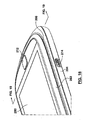
- FIG 12 illustrates an inner or rear side 248 of the upper housing 202.
- a cover plate 250 is affixed or mounted to the rear side 248 along the bottom side 205, extending generally between lateral sides 252, 254 of the upper housing 202.
- a portion 264 of a primary flex connector (described below), which provides electrical connectivity between the upper housing 202 and the lower housing 204.
- fasteners 256 can be used to affix the cover plate 250 to the upper housing 202.
- the cover plate 250 can be provided with tabs (not shown) and corresponding receiving slots (not shown) can be provided in the upper housing 202, the tabs and slots enabling a "snap-fit" arrangement.
- the cover plate 250 can be configured to conceal and protect one or more electrical connections housed in the upper housing 202 from damage during use, and from contaminants such as dirt, moisture and other ingress.
- a flex connector 258 associated with the display 206, a flex connector 260 associated with the navigation keys 230, 232, 236, 238, and a flex connector 262 associated with the auxiliary input device 212 can be arranged directly underneath the cover plate 250.
- Each of the secondary flex connectors 258, 260, 262 are operably connected to the primary flex connector (described below) providing electrical connectivity between the upper housing 202 and the lower housing 204.
- the cover plate 250 also provides ergonomic advantages, as it conceals the flex connectors from view, providing a streamlined look to the device 200.
- a primary flex connector 268 is shown in Figure 14 .
- the primary flex connector 268 provides electrical connectivity between the upper housing 202 and the lower housing 204, and can be referred to as a "dynamic" flex connector.
- the cover plate 250 can be removable after assembly of the portable electronic device 200 to provide access to the flex connectors 258, 260, 262, 268 and other components, either for repairs or troubleshooting.
- the primary flex connector 268 includes the portion 264 that is arranged externally of the upper housing 202 for connection to the lower housing 204.
- the primary flex connector 268 also includes first and second flanking portions 270, 272.
- the first flanking portion 270 is arranged between the auxiliary input device 212 and the lateral side 252.
- the second flanking portion 272 is arranged between the auxiliary input device 212 and the lateral side 254.
- the first flanking portion 270 includes a connecting segment 274 for connection to the flex connector 262, and a connecting segment 276 for connection to the flex connector 260.
- the second flanking portion 272 includes a connecting segment 278 for connection to the flex connector 258.
- the upper housing 202 includes a lens 280, the display 206, a slide housing 282, a slide plate 284, and a guide base 288.
- the guide base 288 can include c-channel structures that allow the guide base 288 to slide relative to the slide plate 284.
- the guide base 288 is affixed to the lower housing 204 (not shown) enabling the upper housing 202 to slide relative thereto.
- an interior region 290 of the cover plate 250 can be arranged underneath and in alignment with the auxiliary input device 212 and provides a backing structure to support the auxiliary input device 212 for examples where the auxiliary input device 212 includes actuator functionality and can be depressed like a button.
- the cover plate 250 can include spacing elements 266 disposed on opposing lateral sides of the cover plate 250.
- the spacing elements 266 engage the lower housing 204 and serve as gap control features for maintaining a generally uniform gap between the upper housing 202 and the lower housing 204 as the upper housing 202 slides between the closed and open positions, as shown in Figures 17 , 18 and 19 .
- the gap provided by the spacing elements 266 effectively accommodates the keypad, which can have a height dimension, preventing the upper portion 202 from rubbing against the keypad 220 as the upper housing 202 slides between the closed and open positions.
- the spacing elements 266 can be configured to bear against and follow a sacrificial wearing surface 292 that is provided on the lower housing 204, disposed about a periphery of the keypad 220.
- the wearing surface 292 can be generally complementary in shape to the spacing elements 266.
Applications Claiming Priority (2)
| Application Number | Priority Date | Filing Date | Title |
|---|---|---|---|
| US30460310P | 2010-02-15 | 2010-02-15 | |
| US13/007,185 US8862190B2 (en) | 2010-02-15 | 2011-01-14 | Portable electronic device with upper housing and cover plate therefor |
Publications (2)
| Publication Number | Publication Date |
|---|---|
| EP2360551A1 true EP2360551A1 (de) | 2011-08-24 |
| EP2360551B1 EP2360551B1 (de) | 2015-01-28 |
Family
ID=43901376
Family Applications (1)
| Application Number | Title | Priority Date | Filing Date |
|---|---|---|---|
| EP20110154518 Active EP2360551B1 (de) | 2010-02-15 | 2011-02-15 | Tragbare elektronische Vorrichtung mit oberem Gehäuse und Abdeckplatte dafür |
Country Status (2)
| Country | Link |
|---|---|
| US (1) | US8862190B2 (de) |
| EP (1) | EP2360551B1 (de) |
Families Citing this family (1)
| Publication number | Priority date | Publication date | Assignee | Title |
|---|---|---|---|---|
| CN108881582B (zh) * | 2018-07-28 | 2024-03-22 | 深圳市力合云记新材料有限公司 | 手写保护套 |
Citations (5)
| Publication number | Priority date | Publication date | Assignee | Title |
|---|---|---|---|---|
| US20050091431A1 (en) * | 2003-10-23 | 2005-04-28 | Robert Olodort | Portable communication devices |
| EP1850211A2 (de) * | 2006-04-25 | 2007-10-31 | Samsung Electronics Co., Ltd. | Tastaturanordnung für ein tragbares Endgerät |
| US20070275774A1 (en) * | 2006-05-26 | 2007-11-29 | Nils Gustav Fagrenius | Flexible gaskets for wireless terminals with sliding members |
| US20090147451A1 (en) * | 2007-12-06 | 2009-06-11 | Chih-Shan Yeh | Electronic device and sliding mechanism thereof |
| EP2088494A1 (de) * | 2006-12-08 | 2009-08-12 | Panasonic Corporation | Tragbares endgerät |
Family Cites Families (14)
| Publication number | Priority date | Publication date | Assignee | Title |
|---|---|---|---|---|
| JP2003179678A (ja) * | 2001-10-03 | 2003-06-27 | Nec Corp | 携帯電話機 |
| US7907121B2 (en) * | 2003-11-19 | 2011-03-15 | Qualcomm Incorporated | Portable device with versatile keyboard |
| KR100617863B1 (ko) * | 2004-03-04 | 2006-08-28 | 주식회사 팬택앤큐리텔 | 이동식 메모리 카드의 탑재가 가능한 슬라이딩 타입 이동통신 단말기 |
| EP2230823A1 (de) | 2004-07-08 | 2010-09-22 | Hitech Parts Co., Ltd. | Schiebeanordnung für ein mobiles Telefon mit Schiebemechanismus und Mobiltelefon mit der Schiebeanordnung |
| KR100630559B1 (ko) | 2004-08-10 | 2006-09-29 | 주식회사 팬택 | 슬림형 이동통신단말기 |
| JP4440324B2 (ja) * | 2006-03-02 | 2010-03-24 | パナソニック株式会社 | 携帯端末 |
| KR100703466B1 (ko) * | 2006-04-03 | 2007-04-03 | 삼성전자주식회사 | 슬림형 휴대 단말기 |
| KR101086704B1 (ko) * | 2006-09-29 | 2011-11-25 | 엘지전자 주식회사 | 회전과 슬라이딩 구동이 가능한 휴대 단말기 및 상기 휴대단말기에 장착되는 스위블 조립체 |
| ATE523031T1 (de) * | 2006-12-21 | 2011-09-15 | Sharp Kk | Verbundspulenfeder und damit ausgerüstetes mobiles endgerät mit gleitmechanismus |
| JP2008187154A (ja) * | 2007-01-31 | 2008-08-14 | Nitto Denko Corp | フレキシブル配線回路基板の接続構造および電子機器 |
| WO2009078057A1 (ja) * | 2007-12-14 | 2009-06-25 | Fujitsu Limited | 表示パネル構造体、それを用いた電子装置、および携帯型情報機器 |
| US8107229B2 (en) | 2008-03-14 | 2012-01-31 | Sony Ericsson Mobile Communications Ab | Portable communication device having a printed circuit board slider hinge assembly |
| US20110136551A1 (en) * | 2009-12-09 | 2011-06-09 | Joshua Kwan Ho Wong | Mobile communication device with rf communication between parts |
| US9210240B2 (en) * | 2010-02-15 | 2015-12-08 | Blackberry Limited | Portable slidable electronic device having a dynamic flex alignment scheme and methods of assembling same |
-
2011
- 2011-01-14 US US13/007,185 patent/US8862190B2/en active Active
- 2011-02-15 EP EP20110154518 patent/EP2360551B1/de active Active
Patent Citations (5)
| Publication number | Priority date | Publication date | Assignee | Title |
|---|---|---|---|---|
| US20050091431A1 (en) * | 2003-10-23 | 2005-04-28 | Robert Olodort | Portable communication devices |
| EP1850211A2 (de) * | 2006-04-25 | 2007-10-31 | Samsung Electronics Co., Ltd. | Tastaturanordnung für ein tragbares Endgerät |
| US20070275774A1 (en) * | 2006-05-26 | 2007-11-29 | Nils Gustav Fagrenius | Flexible gaskets for wireless terminals with sliding members |
| EP2088494A1 (de) * | 2006-12-08 | 2009-08-12 | Panasonic Corporation | Tragbares endgerät |
| US20090147451A1 (en) * | 2007-12-06 | 2009-06-11 | Chih-Shan Yeh | Electronic device and sliding mechanism thereof |
Also Published As
| Publication number | Publication date |
|---|---|
| US8862190B2 (en) | 2014-10-14 |
| EP2360551B1 (de) | 2015-01-28 |
| US20110201389A1 (en) | 2011-08-18 |
Similar Documents
| Publication | Publication Date | Title |
|---|---|---|
| US8711099B2 (en) | Handheld electronic communication device having sliding display | |
| US8965465B2 (en) | Portable electronic device having at least one of resonator and shield | |
| US10061394B2 (en) | Electronic device including keypad with keys having a ridged surface profile | |
| EP2360551B1 (de) | Tragbare elektronische Vorrichtung mit oberem Gehäuse und Abdeckplatte dafür | |
| CA2731763C (en) | Portable electronic device with upper housing and cover plate therefor | |
| CA2731087C (en) | Portable electronic device with auxiliary input device and flex connector therefor | |
| US8638556B2 (en) | Electronic device including a front bezel operable to secure the device together | |
| CA2730825C (en) | Portable electronic device with battery cover and locking mechanism therefor | |
| EP2537079B1 (de) | Tragbare und verschiebbare elektronische vorrichtung mit einem dynamischen flex-ausrichtungsschema und verfahren zu ihrer montage | |
| EP2498478B1 (de) | Verschiebbare tragbare elektronische Vorrichtung mit zum Abdecken der Anzeige angepasstem Tastaturteil | |
| CA2692875A1 (en) | Electronic device including breakthrough antenna |
Legal Events
| Date | Code | Title | Description |
|---|---|---|---|
| PUAI | Public reference made under article 153(3) epc to a published international application that has entered the european phase |
Free format text: ORIGINAL CODE: 0009012 |
|
| PUAI | Public reference made under article 153(3) epc to a published international application that has entered the european phase |
Free format text: ORIGINAL CODE: 0009012 |
|
| 17P | Request for examination filed |
Effective date: 20110215 |
|
| AK | Designated contracting states |
Kind code of ref document: A1 Designated state(s): AL AT BE BG CH CY CZ DE DK EE ES FI FR GB GR HR HU IE IS IT LI LT LU LV MC MK MT NL NO PL PT RO RS SE SI SK SM TR |
|
| AX | Request for extension of the european patent |
Extension state: BA ME |
|
| RAP1 | Party data changed (applicant data changed or rights of an application transferred) |
Owner name: RESEARCH IN MOTION LIMITED |
|
| RAP1 | Party data changed (applicant data changed or rights of an application transferred) |
Owner name: BLACKBERRY LIMITED |
|
| RAP1 | Party data changed (applicant data changed or rights of an application transferred) |
Owner name: BLACKBERRY LIMITED |
|
| GRAP | Despatch of communication of intention to grant a patent |
Free format text: ORIGINAL CODE: EPIDOSNIGR1 |
|
| INTG | Intention to grant announced |
Effective date: 20140827 |
|
| GRAS | Grant fee paid |
Free format text: ORIGINAL CODE: EPIDOSNIGR3 |
|
| GRAA | (expected) grant |
Free format text: ORIGINAL CODE: 0009210 |
|
| AK | Designated contracting states |
Kind code of ref document: B1 Designated state(s): AL AT BE BG CH CY CZ DE DK EE ES FI FR GB GR HR HU IE IS IT LI LT LU LV MC MK MT NL NO PL PT RO RS SE SI SK SM TR |
|
| REG | Reference to a national code |
Ref country code: GB Ref legal event code: FG4D |
|
| REG | Reference to a national code |
Ref country code: CH Ref legal event code: EP |
|
| REG | Reference to a national code |
Ref country code: DE Ref legal event code: R082 Ref document number: 602011013456 Country of ref document: DE Representative=s name: MERH-IP MATIAS ERNY REICHL HOFFMANN, DE Ref country code: DE Ref legal event code: R082 Ref document number: 602011013456 Country of ref document: DE Representative=s name: MERH-IP MATIAS ERNY REICHL HOFFMANN PATENTANWA, DE |
|
| REG | Reference to a national code |
Ref country code: IE Ref legal event code: FG4D |
|
| REG | Reference to a national code |
Ref country code: DE Ref legal event code: R096 Ref document number: 602011013456 Country of ref document: DE Effective date: 20150312 |
|
| REG | Reference to a national code |
Ref country code: AT Ref legal event code: REF Ref document number: 708498 Country of ref document: AT Kind code of ref document: T Effective date: 20150315 |
|
| REG | Reference to a national code |
Ref country code: AT Ref legal event code: MK05 Ref document number: 708498 Country of ref document: AT Kind code of ref document: T Effective date: 20150128 |
|
| REG | Reference to a national code |
Ref country code: LT Ref legal event code: MG4D |
|
| PG25 | Lapsed in a contracting state [announced via postgrant information from national office to epo] |
Ref country code: BE Free format text: LAPSE BECAUSE OF NON-PAYMENT OF DUE FEES Effective date: 20150228 |
|
| PG25 | Lapsed in a contracting state [announced via postgrant information from national office to epo] |
Ref country code: BG Free format text: LAPSE BECAUSE OF FAILURE TO SUBMIT A TRANSLATION OF THE DESCRIPTION OR TO PAY THE FEE WITHIN THE PRESCRIBED TIME-LIMIT Effective date: 20150428 Ref country code: SE Free format text: LAPSE BECAUSE OF FAILURE TO SUBMIT A TRANSLATION OF THE DESCRIPTION OR TO PAY THE FEE WITHIN THE PRESCRIBED TIME-LIMIT Effective date: 20150128 Ref country code: HR Free format text: LAPSE BECAUSE OF FAILURE TO SUBMIT A TRANSLATION OF THE DESCRIPTION OR TO PAY THE FEE WITHIN THE PRESCRIBED TIME-LIMIT Effective date: 20150128 Ref country code: ES Free format text: LAPSE BECAUSE OF FAILURE TO SUBMIT A TRANSLATION OF THE DESCRIPTION OR TO PAY THE FEE WITHIN THE PRESCRIBED TIME-LIMIT Effective date: 20150128 Ref country code: LT Free format text: LAPSE BECAUSE OF FAILURE TO SUBMIT A TRANSLATION OF THE DESCRIPTION OR TO PAY THE FEE WITHIN THE PRESCRIBED TIME-LIMIT Effective date: 20150128 Ref country code: FI Free format text: LAPSE BECAUSE OF FAILURE TO SUBMIT A TRANSLATION OF THE DESCRIPTION OR TO PAY THE FEE WITHIN THE PRESCRIBED TIME-LIMIT Effective date: 20150128 Ref country code: NO Free format text: LAPSE BECAUSE OF FAILURE TO SUBMIT A TRANSLATION OF THE DESCRIPTION OR TO PAY THE FEE WITHIN THE PRESCRIBED TIME-LIMIT Effective date: 20150428 |
|
| PG25 | Lapsed in a contracting state [announced via postgrant information from national office to epo] |
Ref country code: RS Free format text: LAPSE BECAUSE OF FAILURE TO SUBMIT A TRANSLATION OF THE DESCRIPTION OR TO PAY THE FEE WITHIN THE PRESCRIBED TIME-LIMIT Effective date: 20150128 Ref country code: IS Free format text: LAPSE BECAUSE OF FAILURE TO SUBMIT A TRANSLATION OF THE DESCRIPTION OR TO PAY THE FEE WITHIN THE PRESCRIBED TIME-LIMIT Effective date: 20150528 Ref country code: AT Free format text: LAPSE BECAUSE OF FAILURE TO SUBMIT A TRANSLATION OF THE DESCRIPTION OR TO PAY THE FEE WITHIN THE PRESCRIBED TIME-LIMIT Effective date: 20150128 Ref country code: LV Free format text: LAPSE BECAUSE OF FAILURE TO SUBMIT A TRANSLATION OF THE DESCRIPTION OR TO PAY THE FEE WITHIN THE PRESCRIBED TIME-LIMIT Effective date: 20150128 Ref country code: PL Free format text: LAPSE BECAUSE OF FAILURE TO SUBMIT A TRANSLATION OF THE DESCRIPTION OR TO PAY THE FEE WITHIN THE PRESCRIBED TIME-LIMIT Effective date: 20150128 Ref country code: GR Free format text: LAPSE BECAUSE OF FAILURE TO SUBMIT A TRANSLATION OF THE DESCRIPTION OR TO PAY THE FEE WITHIN THE PRESCRIBED TIME-LIMIT Effective date: 20150429 |
|
| REG | Reference to a national code |
Ref country code: CH Ref legal event code: PL |
|
| REG | Reference to a national code |
Ref country code: DE Ref legal event code: R097 Ref document number: 602011013456 Country of ref document: DE |
|
| PG25 | Lapsed in a contracting state [announced via postgrant information from national office to epo] |
Ref country code: SK Free format text: LAPSE BECAUSE OF FAILURE TO SUBMIT A TRANSLATION OF THE DESCRIPTION OR TO PAY THE FEE WITHIN THE PRESCRIBED TIME-LIMIT Effective date: 20150128 Ref country code: CZ Free format text: LAPSE BECAUSE OF FAILURE TO SUBMIT A TRANSLATION OF THE DESCRIPTION OR TO PAY THE FEE WITHIN THE PRESCRIBED TIME-LIMIT Effective date: 20150128 Ref country code: EE Free format text: LAPSE BECAUSE OF FAILURE TO SUBMIT A TRANSLATION OF THE DESCRIPTION OR TO PAY THE FEE WITHIN THE PRESCRIBED TIME-LIMIT Effective date: 20150128 Ref country code: RO Free format text: LAPSE BECAUSE OF FAILURE TO SUBMIT A TRANSLATION OF THE DESCRIPTION OR TO PAY THE FEE WITHIN THE PRESCRIBED TIME-LIMIT Effective date: 20150128 Ref country code: LI Free format text: LAPSE BECAUSE OF NON-PAYMENT OF DUE FEES Effective date: 20150228 Ref country code: CH Free format text: LAPSE BECAUSE OF NON-PAYMENT OF DUE FEES Effective date: 20150228 Ref country code: MC Free format text: LAPSE BECAUSE OF FAILURE TO SUBMIT A TRANSLATION OF THE DESCRIPTION OR TO PAY THE FEE WITHIN THE PRESCRIBED TIME-LIMIT Effective date: 20150128 Ref country code: DK Free format text: LAPSE BECAUSE OF FAILURE TO SUBMIT A TRANSLATION OF THE DESCRIPTION OR TO PAY THE FEE WITHIN THE PRESCRIBED TIME-LIMIT Effective date: 20150128 |
|
| REG | Reference to a national code |
Ref country code: IE Ref legal event code: MM4A |
|
| PLBE | No opposition filed within time limit |
Free format text: ORIGINAL CODE: 0009261 |
|
| STAA | Information on the status of an ep patent application or granted ep patent |
Free format text: STATUS: NO OPPOSITION FILED WITHIN TIME LIMIT |
|
| PG25 | Lapsed in a contracting state [announced via postgrant information from national office to epo] |
Ref country code: IT Free format text: LAPSE BECAUSE OF FAILURE TO SUBMIT A TRANSLATION OF THE DESCRIPTION OR TO PAY THE FEE WITHIN THE PRESCRIBED TIME-LIMIT Effective date: 20150128 |
|
| 26N | No opposition filed |
Effective date: 20151029 |
|
| PG25 | Lapsed in a contracting state [announced via postgrant information from national office to epo] |
Ref country code: IE Free format text: LAPSE BECAUSE OF NON-PAYMENT OF DUE FEES Effective date: 20150215 |
|
| REG | Reference to a national code |
Ref country code: FR Ref legal event code: PLFP Year of fee payment: 6 |
|
| PG25 | Lapsed in a contracting state [announced via postgrant information from national office to epo] |
Ref country code: SI Free format text: LAPSE BECAUSE OF FAILURE TO SUBMIT A TRANSLATION OF THE DESCRIPTION OR TO PAY THE FEE WITHIN THE PRESCRIBED TIME-LIMIT Effective date: 20150128 |
|
| PG25 | Lapsed in a contracting state [announced via postgrant information from national office to epo] |
Ref country code: BE Free format text: LAPSE BECAUSE OF FAILURE TO SUBMIT A TRANSLATION OF THE DESCRIPTION OR TO PAY THE FEE WITHIN THE PRESCRIBED TIME-LIMIT Effective date: 20150128 |
|
| PG25 | Lapsed in a contracting state [announced via postgrant information from national office to epo] |
Ref country code: MT Free format text: LAPSE BECAUSE OF FAILURE TO SUBMIT A TRANSLATION OF THE DESCRIPTION OR TO PAY THE FEE WITHIN THE PRESCRIBED TIME-LIMIT Effective date: 20150128 |
|
| REG | Reference to a national code |
Ref country code: FR Ref legal event code: PLFP Year of fee payment: 7 |
|
| PG25 | Lapsed in a contracting state [announced via postgrant information from national office to epo] |
Ref country code: SM Free format text: LAPSE BECAUSE OF FAILURE TO SUBMIT A TRANSLATION OF THE DESCRIPTION OR TO PAY THE FEE WITHIN THE PRESCRIBED TIME-LIMIT Effective date: 20150128 Ref country code: HU Free format text: LAPSE BECAUSE OF FAILURE TO SUBMIT A TRANSLATION OF THE DESCRIPTION OR TO PAY THE FEE WITHIN THE PRESCRIBED TIME-LIMIT; INVALID AB INITIO Effective date: 20110215 |
|
| PG25 | Lapsed in a contracting state [announced via postgrant information from national office to epo] |
Ref country code: CY Free format text: LAPSE BECAUSE OF FAILURE TO SUBMIT A TRANSLATION OF THE DESCRIPTION OR TO PAY THE FEE WITHIN THE PRESCRIBED TIME-LIMIT Effective date: 20150128 |
|
| PG25 | Lapsed in a contracting state [announced via postgrant information from national office to epo] |
Ref country code: PT Free format text: LAPSE BECAUSE OF FAILURE TO SUBMIT A TRANSLATION OF THE DESCRIPTION OR TO PAY THE FEE WITHIN THE PRESCRIBED TIME-LIMIT Effective date: 20150528 |
|
| PG25 | Lapsed in a contracting state [announced via postgrant information from national office to epo] |
Ref country code: TR Free format text: LAPSE BECAUSE OF FAILURE TO SUBMIT A TRANSLATION OF THE DESCRIPTION OR TO PAY THE FEE WITHIN THE PRESCRIBED TIME-LIMIT Effective date: 20150128 |
|
| PG25 | Lapsed in a contracting state [announced via postgrant information from national office to epo] |
Ref country code: LU Free format text: LAPSE BECAUSE OF NON-PAYMENT OF DUE FEES Effective date: 20150215 |
|
| REG | Reference to a national code |
Ref country code: FR Ref legal event code: PLFP Year of fee payment: 8 |
|
| PG25 | Lapsed in a contracting state [announced via postgrant information from national office to epo] |
Ref country code: MK Free format text: LAPSE BECAUSE OF FAILURE TO SUBMIT A TRANSLATION OF THE DESCRIPTION OR TO PAY THE FEE WITHIN THE PRESCRIBED TIME-LIMIT Effective date: 20150128 |
|
| PG25 | Lapsed in a contracting state [announced via postgrant information from national office to epo] |
Ref country code: AL Free format text: LAPSE BECAUSE OF FAILURE TO SUBMIT A TRANSLATION OF THE DESCRIPTION OR TO PAY THE FEE WITHIN THE PRESCRIBED TIME-LIMIT Effective date: 20150128 |
|
| PGFP | Annual fee paid to national office [announced via postgrant information from national office to epo] |
Ref country code: FR Payment date: 20230223 Year of fee payment: 13 |
|
| PGFP | Annual fee paid to national office [announced via postgrant information from national office to epo] |
Ref country code: NL Payment date: 20240226 Year of fee payment: 14 |
|
| PGFP | Annual fee paid to national office [announced via postgrant information from national office to epo] |
Ref country code: DE Payment date: 20240228 Year of fee payment: 14 Ref country code: GB Payment date: 20240220 Year of fee payment: 14 |