EP2360445A1 - A recoil absorbing assembly for automatic weapons - Google Patents
A recoil absorbing assembly for automatic weapons Download PDFInfo
- Publication number
- EP2360445A1 EP2360445A1 EP10154494A EP10154494A EP2360445A1 EP 2360445 A1 EP2360445 A1 EP 2360445A1 EP 10154494 A EP10154494 A EP 10154494A EP 10154494 A EP10154494 A EP 10154494A EP 2360445 A1 EP2360445 A1 EP 2360445A1
- Authority
- EP
- European Patent Office
- Prior art keywords
- main shaft
- friction
- recoil absorbing
- absorbing assembly
- assembly according
- Prior art date
- Legal status (The legal status is an assumption and is not a legal conclusion. Google has not performed a legal analysis and makes no representation as to the accuracy of the status listed.)
- Granted
Links
Images


Classifications
-
- F—MECHANICAL ENGINEERING; LIGHTING; HEATING; WEAPONS; BLASTING
- F41—WEAPONS
- F41A—FUNCTIONAL FEATURES OR DETAILS COMMON TO BOTH SMALLARMS AND ORDNANCE, e.g. CANNONS; MOUNTINGS FOR SMALLARMS OR ORDNANCE
- F41A25/00—Gun mountings permitting recoil or return to battery, e.g. gun cradles; Barrel buffers or brakes
- F41A25/06—Friction-operated systems
- F41A25/08—Friction-operated systems adjustable
-
- F—MECHANICAL ENGINEERING; LIGHTING; HEATING; WEAPONS; BLASTING
- F41—WEAPONS
- F41A—FUNCTIONAL FEATURES OR DETAILS COMMON TO BOTH SMALLARMS AND ORDNANCE, e.g. CANNONS; MOUNTINGS FOR SMALLARMS OR ORDNANCE
- F41A25/00—Gun mountings permitting recoil or return to battery, e.g. gun cradles; Barrel buffers or brakes
- F41A25/10—Spring-operated systems
- F41A25/12—Spring-operated systems using coil springs
- F41A25/14—Spring-operated systems using coil springs adjustable
Definitions
- the present invention relates to a recoil absorbing assembly for automatic weapons, and in particular an assembly in which the recoil energy is absorbed by means of spring and friction force.
- a recoil absorbing assembly for automatic weapons secured to a weapon cradle having an fixed portion and a portion longitudinally movable thereto, the fixed cradle portion being rotatably mounted to a support, comprising a recoil absorbing spring and friction means arranged in connection with the cradle portions, wherein the friction means are including a main shaft provided with angled friction blocks and a movable bearing housing surrounding the main shaft and having free floating pistons as to cooperate with the friction blocks, the recoil absorbing spring being situated on the main shaft in elongation of the bearing housing.
- the main shaft is provided with means tuning the friction by pushing the friction blocks outwards.
- the friction tuning means can include a shaft portion longitudinally movable using a tension sleeve arranged in an end of the mains shaft opposite of the friction blocks.
- the angled friction blocks are formed with inclined surfaces adjacent corresponding surface portions of the main shaft. Friction block surfaces opposite of the main shaft can be inclined vertically. Further, the free floating pistons can be situated in a manner forming an angle to the main shaft, preferentially 4°. The free floating pistons can be provided with friction increasing portions adjacent the friction blocks, and spring biased against the friction blocks.
- the bearing housing is formed with bearings arranged at each end thereof and surrounding the main shaft.
- the bearings can be made from metal, preferentially bronze.
- the main shaft is connected to the fixed cradle portion, whereas the bearing housing is connected to the movable cradle portion by preferentially using brackets situated in each end of the main shaft and one end of the bearing housing, respectively.
- the present recoil absorbing assembly allows for mounting and firing of automatic weapons such as heavy machine guns and 40mm automatic grenade launchers from the soft-mount.
- the recoil is absorbed by using spring force and decreasing/increasing friction which transfers the recoil energy into heat. Thereby, the precision during firing is increased and the weight of the unit including inter alia the recoil absorbing assembly and weapon cradle is reduced.
- the recoil absorbing assembly consists of two main parts.
- a main shaft including the angled and adjustable friction blocks and its integrated tuning means.
- the main shaft also acts as a guide for the recoil spring.
- the second main part is the bearing housing which during recoil travels back and forth along the main shaft.
- the integrated tuning assembly allows the operator to tune the friction force involving that the two friction blocks are pushed outwards. By tuning the friction force, an adaptation to the different weapons it is possible as to get maximum dampening effect and achieve reliability of the weapons also when firing at high elevations.
- the recoil spring is also having separate tuning means involving that its spring force needed can be set for the actual weapons.
- the recoil absorbing assembly allows mounting and firing of automatic weapons such as heavy machine guns and 40mm automatic grenade launchers from the soft-mount.
- automatic weapons such as heavy machine guns and 40mm automatic grenade launchers from the soft-mount.
- a weapon cradle having a fixed portion 1 and a portion 2 longitudinally movable thereto.
- the fixed cradle portion is rotatably mounted to a suitable support, not shown, by means of a pin connection 25, for instance.
- the fixed and movable cradle portions can be formed in any appropriate manner but these features are not part of the present invention and are not be discussed in detail herein as well as the others depicted in Fig. 4a-b .
- the present assembly includes a recoil absorbing spring 3 and friction means 4, 5 known per se and arranged in connection with the cradle portions.
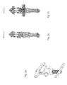
- the present friction means include a main shaft 4 provided with angled friction blocks 6, 7 and a movable bearing housing 5 surrounding the main shaft and having free floating pistons 8, 9 as to cooperate with the friction blocks, whereas the recoil absorbing spring 3 being situated on the main shaft in elongation of the bearing housing; cf. Fig. 1e , for instance. 11.
- the main shaft 4 is connected to the fixed cradle portion 1, whereas the bearing housing 5 is connected to the movable cradle postion.2 by preferentially using brackets 22, 23, 24 situated in each end of the main shaft and one end of the bearing housing, respectively, see Fig. 1a . It is understood that the brackets illustrated can be replaced by other suitable means.
- the angled friction blocks 6, 7 are formed with inclined surfaces 12, 13 adjacent corre-spending surface portions 14, 15 of the main shaft 4.
- the respective inclined surfaces and surface portions of the friction blocks and main shaft, respectively, are preferentially planar but this other configurations such as angled or curved are not excluded.
- the friction effect is increased by means of friction block surfaces 16, 17 opposite of the main shaft portion 10 being vertically inclined. The slope of these surfaces can be varied as to fit to different weapon and ammunition types.
- the main shaft 4 is provided with means 10, 11 tuning the friction by pushing the friction blocks 6, 7 outwards.
- These means could include a main shaft portion 10 longitudinally movable using a tension sleeve 11 arranged in an end of the mains shaft 4 opposite of the friction blocks 6, 7.
- the shaft portion and tension sleeve are arranged in connection with a bore within the main shaft and are mutually rotatably using a ball bearing 26, for instance. These can be secured using appropriate means.
- the movable bearing housing 5 is formed with bearings 18,19 arranged at each end thereof and surrounding the main shaft 4, see Fig. 1c . These bearings are made from metal, preferentially bronze.
- the free floating pistons 8, 9 arranged in the bearing housing 5 are situated in a manner forming an angle to the main shaft 4, preferentially 4°.
- the pistons are within apertures 26, 27 made therethrough and are communicating with corresponding aperture 28, 29 formed in the main shaft 4, whereby the friction blocks 6, 7 are pressed against the shaft portion 10.
- the floating pistons are provided with friction increasing portions 20, 21 adjacent the friction blocks and are spring biased against these friction blocks.
- the floating pistons are preferentially biased using cup springs 30, 31 but other types of springs are also applicable.
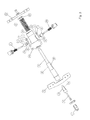
- Fig. 1-3 illustrate more elements than discussed above, these shall only be considered as examples of supplementary accessories and not understood in a restrict manner. Moreover, it is noted that the exploded view in Fig. 3 is not including the bearings 18, 19 situated in each end of the bearing housing 5. The spring force of the recoil spring 3 can be adjusted to different types of weapons and ammunitions by means of appropriate means such as a set screw 32.
Landscapes
- Engineering & Computer Science (AREA)
- General Engineering & Computer Science (AREA)
- Toys (AREA)
Abstract
Description
- The present invention relates to a recoil absorbing assembly for automatic weapons, and in particular an assembly in which the recoil energy is absorbed by means of spring and friction force.
- A lot of solutions similar to the assembly mentioned above is known in the prior art. One typical example is presented by
US-A 5,159,148 in which the friction force is effected by means of sliding guides comprising a bolt secured to the fixed cradle portion and protruding through a slot in the movable cradle portion and more than one such sliding guide are needed i.e. often three pairs at the longitudinal sides of the two cradle portions. Despite this fact and due to torsional movements, practice has also proved that the precision during firing is not satisfactorily involving that the actual targets are missed. Another secondary disantages are increased weight and manufacturing costs. - The objects of the present invention are to remedy this disadvantages and tthese are achieved by a recoil absorbing assembly for automatic weapons secured to a weapon cradle having an fixed portion and a portion longitudinally movable thereto, the fixed cradle portion being rotatably mounted to a support, comprising a recoil absorbing spring and friction means arranged in connection with the cradle portions, wherein the friction means are including a main shaft provided with angled friction blocks and a movable bearing housing surrounding the main shaft and having free floating pistons as to cooperate with the friction blocks, the recoil absorbing spring being situated on the main shaft in elongation of the bearing housing.
- To adapt the present recoil absorbing assembly to different types of automatic weapons and ammunitions, the main shaft is provided with means tuning the friction by pushing the friction blocks outwards. The friction tuning means can include a shaft portion longitudinally movable using a tension sleeve arranged in an end of the mains shaft opposite of the friction blocks.
- To further increase the friction effect, the angled friction blocks are formed with inclined surfaces adjacent corresponding surface portions of the main shaft. Friction block surfaces opposite of the main shaft can be inclined vertically. Further, the free floating pistons can be situated in a manner forming an angle to the main shaft, preferentially 4°. The free floating pistons can be provided with friction increasing portions adjacent the friction blocks, and spring biased against the friction blocks.
- To enable unobstructed longitudinal movements relatively to the main shaft, the bearing housing is formed with bearings arranged at each end thereof and surrounding the main shaft. The bearings can be made from metal, preferentially bronze.
- To secure the recoil absorbing assembly, the main shaft is connected to the fixed cradle portion, whereas the bearing housing is connected to the movable cradle portion by preferentially using brackets situated in each end of the main shaft and one end of the bearing housing, respectively.
- The present recoil absorbing assembly allows for mounting and firing of automatic weapons such as heavy machine guns and 40mm automatic grenade launchers from the soft-mount. The recoil is absorbed by using spring force and decreasing/increasing friction which transfers the recoil energy into heat. Thereby, the precision during firing is increased and the weight of the unit including inter alia the recoil absorbing assembly and weapon cradle is reduced.
- The recoil absorbing assembly according to the present invention consists of two main parts. A main shaft including the angled and adjustable friction blocks and its integrated tuning means. The main shaft also acts as a guide for the recoil spring. The second main part is the bearing housing which during recoil travels back and forth along the main shaft. When the assembly is in its forward i.e. extracted position, the recoil spring is preloaded and the forward position is hold by the friction force created by the two pistons trusting against the friction blocks inside the main shaft. When the recoil of the weapon pushes the bearing housing rearwards the recoil spring is compressed and the friction force is slowly decreasing due to the angled friction blocks. On its return, the increasing friction force creates a "soft stop" of the assembly before it enters the physical end stop of the assembly.
- The integrated tuning assembly allows the operator to tune the friction force involving that the two friction blocks are pushed outwards. By tuning the friction force, an adaptation to the different weapons it is possible as to get maximum dampening effect and achieve reliability of the weapons also when firing at high elevations. The recoil spring is also having separate tuning means involving that its spring force needed can be set for the actual weapons.
- Now, the present invention is to be discussed in detail with reference to preferred embodiment illustrated in the accompanying drawings, in which:
-
Fig. 1a-e show an recoil absorbing assembly in bottom and front perspective, vertical sectional, side perspective and horizontal sectional views, respectively, presented in a extended position; -
Fig. 2a-c show the same assembly in bottom perspective, vertical and horizontal sectional views, respectively, presented in the compressed position; -
Fig. 3 shows an exploded top perspective view of the same assembly; and -
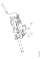
Fig. 4a-b show the assembly used for different types of automatic weapons in perspective views, seen from the left and right hand sides. - According to the present invention, the recoil absorbing assembly allows mounting and firing of automatic weapons such as heavy machine guns and 40mm automatic grenade launchers from the soft-mount. As illustrated in
Fig. 4a-b , two different weapons are mounted in a weapon cradle having a fixed portion 1 and aportion 2 longitudinally movable thereto. The fixed cradle portion is rotatably mounted to a suitable support, not shown, by means of apin connection 25, for instance. The fixed and movable cradle portions can be formed in any appropriate manner but these features are not part of the present invention and are not be discussed in detail herein as well as the others depicted inFig. 4a-b . - As shown in
Fig. 1-3 , the present assembly includes arecoil absorbing spring 3 and friction means 4, 5 known per se and arranged in connection with the cradle portions. However, contrary to the prior art the present friction means include amain shaft 4 provided with angled friction blocks 6, 7 and a movable bearinghousing 5 surrounding the main shaft and having freefloating pistons recoil absorbing spring 3 being situated on the main shaft in elongation of the bearing housing; cf.Fig. 1e , for instance. 11. Themain shaft 4 is connected to the fixed cradle portion 1, whereas the bearinghousing 5 is connected to the movable cradle postion.2 by preferentially usingbrackets Fig. 1a . It is understood that the brackets illustrated can be replaced by other suitable means. - The angled friction blocks 6, 7 are formed with
inclined surfaces spending surface portions main shaft 4. The respective inclined surfaces and surface portions of the friction blocks and main shaft, respectively, are preferentially planar but this other configurations such as angled or curved are not excluded. The friction effect is increased by means offriction block surfaces 16, 17 opposite of themain shaft portion 10 being vertically inclined. The slope of these surfaces can be varied as to fit to different weapon and ammunition types. - Further, the
main shaft 4 is provided withmeans 10, 11 tuning the friction by pushing the friction blocks 6, 7 outwards. These means could include amain shaft portion 10 longitudinally movable using a tension sleeve 11 arranged in an end of themains shaft 4 opposite of the friction blocks 6, 7. The shaft portion and tension sleeve are arranged in connection with a bore within the main shaft and are mutually rotatably using a ball bearing 26, for instance. These can be secured using appropriate means. - The movable bearing
housing 5 is formed withbearings main shaft 4, seeFig. 1c . These bearings are made from metal, preferentially bronze. - The free
floating pistons housing 5 are situated in a manner forming an angle to themain shaft 4, preferentially 4°. The pistons are withinapertures corresponding aperture 28, 29 formed in themain shaft 4, whereby the friction blocks 6, 7 are pressed against theshaft portion 10. Additionally, the floating pistons are provided withfriction increasing portions cup springs - Although
Fig. 1-3 illustrate more elements than discussed above, these shall only be considered as examples of supplementary accessories and not understood in a restrict manner. Moreover, it is noted that the exploded view inFig. 3 is not including thebearings housing 5. The spring force of therecoil spring 3 can be adjusted to different types of weapons and ammunitions by means of appropriate means such as aset screw 32.
Claims (11)
- A recoil absorbing assembly for automatic weapons secured to a weapon cradle having an fixed portion (1) and a portion (2) movable longitudinally thereto, the fixed cradle portion being rotatably mounted to a support, comprising a recoil absorbing spring (3) and friction means (4, 5) arranged in connection with the cradle portions, characterized i n that the friction means are including a main shaft (4) provided with angled friction blocks (6, 7) and a movable bearing housing (5) surrounding the main shaft and having free floating pistons (8, 9) as to cooperate with the friction blocks, the recoil absorbing spring (3) being situated on the main shaft in elongation of the bearing housing.
- A recoil absorbing assembly according to claim 2, character ized in that the main shaft (4) is provided with means (10, 11) tuning the friction by pushing the friction blocks (6, 7) outwards.
- A recoil absorbing assembly according to claim 2, characterized in that the friction tuning means include a shaft portion (10) longitudinally movable using a tension sleeve (11) arranged in an end of the mains shaft (4) opposite of the friction blocks (6, 7).
- A recoil absorbing assembly according to any of the preceding claims, characterized in that the angled friction blocks (6, 7) are formed with inclined surfaces (12, 13) adjacent corresponding surface portions (14, 15) of the main shaft (4).
- A recoil absorbing assembly according to claim 4, characterized in that friction block surfaces (16, 17) opposite of the main shaft portion (10) are inclined vertically.
- A recoil absorbing assembly according to any of the preceding claims, characterized in that the movable bearing housing (5) is formed with bearings (18, 19) arranged at each end thereof and surrounding the main shaft (4).
- A recoil absorbing assembly according to claim 6, characterized in that the bearings (18, 19) are made from metal, preferentially bronze.
- A recoil absorbing assembly according to any of the preceding claims, characterized in that the free floating pistons (8, 9) are situated in a manner forming an angle to the main shaft (4), preferentially 4°.
- A recoil absorbing assembly according to claim 8, characterized in that the free floating pistons (8, 9) are provided with friction increasing portions (20, 21) adjacent the friction blocks (6, 7).
- A recoil absorbing assembly according to any of the preceding claims, charactcrized in that the free floating pistons (8, 9) are spring biased against the friction blocks (6, 7).
- A recoil absorbing assembly according to any of the preceding claims, characterized in that the main shaft (4) is connected to the fixed cradle portion (1), whereas the bearing housing (5) is connected to the movable cradle portion.(2) by using brackets (22, 23, 24) situated in each end of the main shaft and one end of the bearing housing, respectively.
Priority Applications (1)
| Application Number | Priority Date | Filing Date | Title |
|---|---|---|---|
| EP20100154494 EP2360445B1 (en) | 2010-02-24 | 2010-02-24 | A recoil absorbing assembly for automatic weapons |
Applications Claiming Priority (1)
| Application Number | Priority Date | Filing Date | Title |
|---|---|---|---|
| EP20100154494 EP2360445B1 (en) | 2010-02-24 | 2010-02-24 | A recoil absorbing assembly for automatic weapons |
Publications (2)
| Publication Number | Publication Date |
|---|---|
| EP2360445A1 true EP2360445A1 (en) | 2011-08-24 |
| EP2360445B1 EP2360445B1 (en) | 2013-08-21 |
Family
ID=42272685
Family Applications (1)
| Application Number | Title | Priority Date | Filing Date |
|---|---|---|---|
| EP20100154494 Not-in-force EP2360445B1 (en) | 2010-02-24 | 2010-02-24 | A recoil absorbing assembly for automatic weapons |
Country Status (1)
| Country | Link |
|---|---|
| EP (1) | EP2360445B1 (en) |
Citations (6)
| Publication number | Priority date | Publication date | Assignee | Title |
|---|---|---|---|---|
| GB190914804A (en) * | 1908-12-21 | 1910-01-20 | Konrad Haussner | Improvements in or relating to Guns having Differential Recoil. |
| DE730010C (en) * | 1937-07-04 | 1943-01-06 | Mauser Werke Ag | Carriage cushioning with combined braking device |
| GB1386823A (en) * | 1971-03-01 | 1975-03-12 | Int Vibration Engineer | Shock absorbing device for firearms |
| FR2283417A1 (en) * | 1974-02-27 | 1976-03-26 | Int Vibration Engineer | Cushioning of weapon firing in bursts - can be mounted in aircraft using hydraulic means |
| DE8812370U1 (en) * | 1988-09-30 | 1990-02-01 | Mauser-Werke Oberndorf Gmbh, 7238 Oberndorf | Recoil brake for automatic machine guns |
| US5159148A (en) | 1987-04-28 | 1992-10-27 | Vinghogs Mek. Verksted As | Recoil suppressing mount for a manually operated automatic weapon |
-
2010
- 2010-02-24 EP EP20100154494 patent/EP2360445B1/en not_active Not-in-force
Patent Citations (6)
| Publication number | Priority date | Publication date | Assignee | Title |
|---|---|---|---|---|
| GB190914804A (en) * | 1908-12-21 | 1910-01-20 | Konrad Haussner | Improvements in or relating to Guns having Differential Recoil. |
| DE730010C (en) * | 1937-07-04 | 1943-01-06 | Mauser Werke Ag | Carriage cushioning with combined braking device |
| GB1386823A (en) * | 1971-03-01 | 1975-03-12 | Int Vibration Engineer | Shock absorbing device for firearms |
| FR2283417A1 (en) * | 1974-02-27 | 1976-03-26 | Int Vibration Engineer | Cushioning of weapon firing in bursts - can be mounted in aircraft using hydraulic means |
| US5159148A (en) | 1987-04-28 | 1992-10-27 | Vinghogs Mek. Verksted As | Recoil suppressing mount for a manually operated automatic weapon |
| DE8812370U1 (en) * | 1988-09-30 | 1990-02-01 | Mauser-Werke Oberndorf Gmbh, 7238 Oberndorf | Recoil brake for automatic machine guns |
Also Published As
| Publication number | Publication date |
|---|---|
| EP2360445B1 (en) | 2013-08-21 |
Similar Documents
| Publication | Publication Date | Title |
|---|---|---|
| US12480735B2 (en) | Cocking system for a crossbow | |
| US8667727B2 (en) | Device for mounting an additional device to a firearm | |
| EP3069095B1 (en) | Hybrid upper receiver for a rifle | |
| US20100107467A1 (en) | Self adjusting throw lever and rail clamp system | |
| US20100229444A1 (en) | Gunstock | |
| US20150323269A1 (en) | Carrier guide and firearm | |
| US8286541B2 (en) | Firearm with enhanced handling by dissipating the effects of recoil and muzzle climb | |
| PT2350550E (en) | Delayed blowback firearms with novel mechanisms for control of recoil and muzzle climb | |
| GB2094451A (en) | Self-loading firearm | |
| KR101865535B1 (en) | Devices for fixing firearms | |
| RU2683214C1 (en) | Recoil amortization device | |
| US10690440B2 (en) | Stock for a firearm | |
| US10605554B2 (en) | Laterally pivoting trigger lever | |
| US8333141B2 (en) | Recoil absorbing assembly for automatic weapons | |
| US10113827B2 (en) | Firearm recoil control system | |
| EP2354750A2 (en) | Magazine | |
| EP2360445B1 (en) | A recoil absorbing assembly for automatic weapons | |
| US10955205B2 (en) | Bedding block | |
| US870272A (en) | Telescope-sight for firearms. | |
| US10386145B2 (en) | Double barrel adjustment assembly | |
| RU2491489C1 (en) | Automatic firearm | |
| US20110099868A1 (en) | Losok Valkyr Rifle | |
| CN110631409A (en) | Spiral anti-recoil structure, floating gunstock and gun | |
| CA3052943C (en) | Arrangement for reducing recoiling forces on a sight or other component mounted on a barrel of a weapon | |
| EP3361206B1 (en) | Damping butt for a firearm and firearm comprising said butt |
Legal Events
| Date | Code | Title | Description |
|---|---|---|---|
| PUAI | Public reference made under article 153(3) epc to a published international application that has entered the european phase |
Free format text: ORIGINAL CODE: 0009012 |
|
| 17P | Request for examination filed |
Effective date: 20100224 |
|
| AK | Designated contracting states |
Kind code of ref document: A1 Designated state(s): AT BE BG CH CY CZ DE DK EE ES FI FR GB GR HR HU IE IS IT LI LT LU LV MC MK MT NL NO PL PT RO SE SI SK SM TR |
|
| AX | Request for extension of the european patent |
Extension state: AL BA RS |
|
| GRAP | Despatch of communication of intention to grant a patent |
Free format text: ORIGINAL CODE: EPIDOSNIGR1 |
|
| GRAP | Despatch of communication of intention to grant a patent |
Free format text: ORIGINAL CODE: EPIDOSNIGR1 |
|
| GRAS | Grant fee paid |
Free format text: ORIGINAL CODE: EPIDOSNIGR3 |
|
| GRAF | Information related to payment of grant fee modified |
Free format text: ORIGINAL CODE: EPIDOSCIGR3 |
|
| GRAA | (expected) grant |
Free format text: ORIGINAL CODE: 0009210 |
|
| AK | Designated contracting states |
Kind code of ref document: B1 Designated state(s): AT BE BG CH CY CZ DE DK EE ES FI FR GB GR HR HU IE IS IT LI LT LU LV MC MK MT NL NO PL PT RO SE SI SK SM TR |
|
| REG | Reference to a national code |
Ref country code: GB Ref legal event code: FG4D |
|
| REG | Reference to a national code |
Ref country code: CH Ref legal event code: EP |
|
| REG | Reference to a national code |
Ref country code: AT Ref legal event code: REF Ref document number: 628335 Country of ref document: AT Kind code of ref document: T Effective date: 20130915 |
|
| REG | Reference to a national code |
Ref country code: IE Ref legal event code: FG4D |
|
| REG | Reference to a national code |
Ref country code: DE Ref legal event code: R096 Ref document number: 602010009565 Country of ref document: DE Effective date: 20131017 |
|
| REG | Reference to a national code |
Ref country code: NL Ref legal event code: VDEP Effective date: 20130821 Ref country code: AT Ref legal event code: MK05 Ref document number: 628335 Country of ref document: AT Kind code of ref document: T Effective date: 20130821 |
|
| REG | Reference to a national code |
Ref country code: LT Ref legal event code: MG4D |
|
| PG25 | Lapsed in a contracting state [announced via postgrant information from national office to epo] |
Ref country code: NO Free format text: LAPSE BECAUSE OF FAILURE TO SUBMIT A TRANSLATION OF THE DESCRIPTION OR TO PAY THE FEE WITHIN THE PRESCRIBED TIME-LIMIT Effective date: 20131121 Ref country code: SE Free format text: LAPSE BECAUSE OF FAILURE TO SUBMIT A TRANSLATION OF THE DESCRIPTION OR TO PAY THE FEE WITHIN THE PRESCRIBED TIME-LIMIT Effective date: 20130821 Ref country code: AT Free format text: LAPSE BECAUSE OF FAILURE TO SUBMIT A TRANSLATION OF THE DESCRIPTION OR TO PAY THE FEE WITHIN THE PRESCRIBED TIME-LIMIT Effective date: 20130821 Ref country code: PT Free format text: LAPSE BECAUSE OF FAILURE TO SUBMIT A TRANSLATION OF THE DESCRIPTION OR TO PAY THE FEE WITHIN THE PRESCRIBED TIME-LIMIT Effective date: 20131223 Ref country code: IS Free format text: LAPSE BECAUSE OF FAILURE TO SUBMIT A TRANSLATION OF THE DESCRIPTION OR TO PAY THE FEE WITHIN THE PRESCRIBED TIME-LIMIT Effective date: 20131221 Ref country code: CY Free format text: LAPSE BECAUSE OF FAILURE TO SUBMIT A TRANSLATION OF THE DESCRIPTION OR TO PAY THE FEE WITHIN THE PRESCRIBED TIME-LIMIT Effective date: 20130626 Ref country code: LT Free format text: LAPSE BECAUSE OF FAILURE TO SUBMIT A TRANSLATION OF THE DESCRIPTION OR TO PAY THE FEE WITHIN THE PRESCRIBED TIME-LIMIT Effective date: 20130821 Ref country code: HR Free format text: LAPSE BECAUSE OF FAILURE TO SUBMIT A TRANSLATION OF THE DESCRIPTION OR TO PAY THE FEE WITHIN THE PRESCRIBED TIME-LIMIT Effective date: 20130821 |
|
| PG25 | Lapsed in a contracting state [announced via postgrant information from national office to epo] |
Ref country code: BE Free format text: LAPSE BECAUSE OF FAILURE TO SUBMIT A TRANSLATION OF THE DESCRIPTION OR TO PAY THE FEE WITHIN THE PRESCRIBED TIME-LIMIT Effective date: 20130821 Ref country code: LV Free format text: LAPSE BECAUSE OF FAILURE TO SUBMIT A TRANSLATION OF THE DESCRIPTION OR TO PAY THE FEE WITHIN THE PRESCRIBED TIME-LIMIT Effective date: 20130821 Ref country code: GR Free format text: LAPSE BECAUSE OF FAILURE TO SUBMIT A TRANSLATION OF THE DESCRIPTION OR TO PAY THE FEE WITHIN THE PRESCRIBED TIME-LIMIT Effective date: 20131122 Ref country code: PL Free format text: LAPSE BECAUSE OF FAILURE TO SUBMIT A TRANSLATION OF THE DESCRIPTION OR TO PAY THE FEE WITHIN THE PRESCRIBED TIME-LIMIT Effective date: 20130821 Ref country code: SI Free format text: LAPSE BECAUSE OF FAILURE TO SUBMIT A TRANSLATION OF THE DESCRIPTION OR TO PAY THE FEE WITHIN THE PRESCRIBED TIME-LIMIT Effective date: 20130821 Ref country code: FI Free format text: LAPSE BECAUSE OF FAILURE TO SUBMIT A TRANSLATION OF THE DESCRIPTION OR TO PAY THE FEE WITHIN THE PRESCRIBED TIME-LIMIT Effective date: 20130821 |
|
| PG25 | Lapsed in a contracting state [announced via postgrant information from national office to epo] |
Ref country code: CY Free format text: LAPSE BECAUSE OF FAILURE TO SUBMIT A TRANSLATION OF THE DESCRIPTION OR TO PAY THE FEE WITHIN THE PRESCRIBED TIME-LIMIT Effective date: 20130821 |
|
| PG25 | Lapsed in a contracting state [announced via postgrant information from national office to epo] |
Ref country code: CZ Free format text: LAPSE BECAUSE OF FAILURE TO SUBMIT A TRANSLATION OF THE DESCRIPTION OR TO PAY THE FEE WITHIN THE PRESCRIBED TIME-LIMIT Effective date: 20130821 Ref country code: SK Free format text: LAPSE BECAUSE OF FAILURE TO SUBMIT A TRANSLATION OF THE DESCRIPTION OR TO PAY THE FEE WITHIN THE PRESCRIBED TIME-LIMIT Effective date: 20130821 Ref country code: DK Free format text: LAPSE BECAUSE OF FAILURE TO SUBMIT A TRANSLATION OF THE DESCRIPTION OR TO PAY THE FEE WITHIN THE PRESCRIBED TIME-LIMIT Effective date: 20130821 Ref country code: NL Free format text: LAPSE BECAUSE OF FAILURE TO SUBMIT A TRANSLATION OF THE DESCRIPTION OR TO PAY THE FEE WITHIN THE PRESCRIBED TIME-LIMIT Effective date: 20130821 Ref country code: EE Free format text: LAPSE BECAUSE OF FAILURE TO SUBMIT A TRANSLATION OF THE DESCRIPTION OR TO PAY THE FEE WITHIN THE PRESCRIBED TIME-LIMIT Effective date: 20130821 Ref country code: RO Free format text: LAPSE BECAUSE OF FAILURE TO SUBMIT A TRANSLATION OF THE DESCRIPTION OR TO PAY THE FEE WITHIN THE PRESCRIBED TIME-LIMIT Effective date: 20130821 |
|
| PG25 | Lapsed in a contracting state [announced via postgrant information from national office to epo] |
Ref country code: ES Free format text: LAPSE BECAUSE OF FAILURE TO SUBMIT A TRANSLATION OF THE DESCRIPTION OR TO PAY THE FEE WITHIN THE PRESCRIBED TIME-LIMIT Effective date: 20130821 Ref country code: IT Free format text: LAPSE BECAUSE OF FAILURE TO SUBMIT A TRANSLATION OF THE DESCRIPTION OR TO PAY THE FEE WITHIN THE PRESCRIBED TIME-LIMIT Effective date: 20130821 |
|
| PLBE | No opposition filed within time limit |
Free format text: ORIGINAL CODE: 0009261 |
|
| STAA | Information on the status of an ep patent application or granted ep patent |
Free format text: STATUS: NO OPPOSITION FILED WITHIN TIME LIMIT |
|
| 26N | No opposition filed |
Effective date: 20140522 |
|
| REG | Reference to a national code |
Ref country code: DE Ref legal event code: R119 Ref document number: 602010009565 Country of ref document: DE |
|
| REG | Reference to a national code |
Ref country code: DE Ref legal event code: R097 Ref document number: 602010009565 Country of ref document: DE Effective date: 20140522 |
|
| PG25 | Lapsed in a contracting state [announced via postgrant information from national office to epo] |
Ref country code: LU Free format text: LAPSE BECAUSE OF FAILURE TO SUBMIT A TRANSLATION OF THE DESCRIPTION OR TO PAY THE FEE WITHIN THE PRESCRIBED TIME-LIMIT Effective date: 20140224 Ref country code: MC Free format text: LAPSE BECAUSE OF FAILURE TO SUBMIT A TRANSLATION OF THE DESCRIPTION OR TO PAY THE FEE WITHIN THE PRESCRIBED TIME-LIMIT Effective date: 20130821 |
|
| REG | Reference to a national code |
Ref country code: CH Ref legal event code: PL |
|
| GBPC | Gb: european patent ceased through non-payment of renewal fee |
Effective date: 20140224 |
|
| PG25 | Lapsed in a contracting state [announced via postgrant information from national office to epo] |
Ref country code: CH Free format text: LAPSE BECAUSE OF NON-PAYMENT OF DUE FEES Effective date: 20140228 Ref country code: LI Free format text: LAPSE BECAUSE OF NON-PAYMENT OF DUE FEES Effective date: 20140228 |
|
| REG | Reference to a national code |
Ref country code: FR Ref legal event code: ST Effective date: 20141031 |
|
| REG | Reference to a national code |
Ref country code: IE Ref legal event code: MM4A |
|
| REG | Reference to a national code |
Ref country code: DE Ref legal event code: R119 Ref document number: 602010009565 Country of ref document: DE Effective date: 20140902 |
|
| PG25 | Lapsed in a contracting state [announced via postgrant information from national office to epo] |
Ref country code: IE Free format text: LAPSE BECAUSE OF NON-PAYMENT OF DUE FEES Effective date: 20140224 Ref country code: DE Free format text: LAPSE BECAUSE OF NON-PAYMENT OF DUE FEES Effective date: 20140902 Ref country code: FR Free format text: LAPSE BECAUSE OF NON-PAYMENT OF DUE FEES Effective date: 20140228 Ref country code: GB Free format text: LAPSE BECAUSE OF NON-PAYMENT OF DUE FEES Effective date: 20140224 |
|
| PG25 | Lapsed in a contracting state [announced via postgrant information from national office to epo] |
Ref country code: MT Free format text: LAPSE BECAUSE OF FAILURE TO SUBMIT A TRANSLATION OF THE DESCRIPTION OR TO PAY THE FEE WITHIN THE PRESCRIBED TIME-LIMIT Effective date: 20130821 |
|
| PG25 | Lapsed in a contracting state [announced via postgrant information from national office to epo] |
Ref country code: SM Free format text: LAPSE BECAUSE OF FAILURE TO SUBMIT A TRANSLATION OF THE DESCRIPTION OR TO PAY THE FEE WITHIN THE PRESCRIBED TIME-LIMIT Effective date: 20130821 |
|
| PG25 | Lapsed in a contracting state [announced via postgrant information from national office to epo] |
Ref country code: BG Free format text: LAPSE BECAUSE OF FAILURE TO SUBMIT A TRANSLATION OF THE DESCRIPTION OR TO PAY THE FEE WITHIN THE PRESCRIBED TIME-LIMIT Effective date: 20130821 |
|
| PG25 | Lapsed in a contracting state [announced via postgrant information from national office to epo] |
Ref country code: HU Free format text: LAPSE BECAUSE OF FAILURE TO SUBMIT A TRANSLATION OF THE DESCRIPTION OR TO PAY THE FEE WITHIN THE PRESCRIBED TIME-LIMIT; INVALID AB INITIO Effective date: 20100224 Ref country code: TR Free format text: LAPSE BECAUSE OF FAILURE TO SUBMIT A TRANSLATION OF THE DESCRIPTION OR TO PAY THE FEE WITHIN THE PRESCRIBED TIME-LIMIT Effective date: 20130821 |
|
| PG25 | Lapsed in a contracting state [announced via postgrant information from national office to epo] |
Ref country code: MK Free format text: LAPSE BECAUSE OF FAILURE TO SUBMIT A TRANSLATION OF THE DESCRIPTION OR TO PAY THE FEE WITHIN THE PRESCRIBED TIME-LIMIT Effective date: 20130821 |