US10690440B2 - Stock for a firearm - Google Patents
Stock for a firearm Download PDFInfo
- Publication number
- US10690440B2 US10690440B2 US16/121,344 US201816121344A US10690440B2 US 10690440 B2 US10690440 B2 US 10690440B2 US 201816121344 A US201816121344 A US 201816121344A US 10690440 B2 US10690440 B2 US 10690440B2
- Authority
- US
- United States
- Prior art keywords
- side rails
- receiver
- rifle
- rail
- stock
- Prior art date
- Legal status (The legal status is an assumption and is not a legal conclusion. Google has not performed a legal analysis and makes no representation as to the accuracy of the status listed.)
- Active
Links
- 230000009471 action Effects 0.000 claims abstract description 46
- 239000012815 thermoplastic material Substances 0.000 claims description 2
- 238000010304 firing Methods 0.000 description 7
- 230000007246 mechanism Effects 0.000 description 5
- 230000006872 improvement Effects 0.000 description 3
- 239000000463 material Substances 0.000 description 2
- 230000004048 modification Effects 0.000 description 2
- 238000012986 modification Methods 0.000 description 2
- 238000004873 anchoring Methods 0.000 description 1
- 230000005540 biological transmission Effects 0.000 description 1
- 230000008859 change Effects 0.000 description 1
- 230000002950 deficient Effects 0.000 description 1
- 239000000945 filler Substances 0.000 description 1
- 210000000245 forearm Anatomy 0.000 description 1
- 230000000977 initiatory effect Effects 0.000 description 1
- 238000004519 manufacturing process Methods 0.000 description 1
- 229920001225 polyester resin Polymers 0.000 description 1
- 239000004645 polyester resin Substances 0.000 description 1
- 239000000843 powder Substances 0.000 description 1
- 230000000284 resting effect Effects 0.000 description 1
- 229920002994 synthetic fiber Polymers 0.000 description 1
- 239000002023 wood Substances 0.000 description 1
Images


Classifications
-
- F—MECHANICAL ENGINEERING; LIGHTING; HEATING; WEAPONS; BLASTING
- F41—WEAPONS
- F41C—SMALLARMS, e.g. PISTOLS, RIFLES; ACCESSORIES THEREFOR
- F41C23/00—Butts; Butt plates; Stocks
- F41C23/16—Forestocks; Handgrips; Hand guards
-
- F—MECHANICAL ENGINEERING; LIGHTING; HEATING; WEAPONS; BLASTING
- F41—WEAPONS
- F41A—FUNCTIONAL FEATURES OR DETAILS COMMON TO BOTH SMALLARMS AND ORDNANCE, e.g. CANNONS; MOUNTINGS FOR SMALLARMS OR ORDNANCE
- F41A21/00—Barrels; Gun tubes; Muzzle attachments; Barrel mounting means
- F41A21/48—Barrel mounting means, e.g. releasable mountings for replaceable barrels
-
- F—MECHANICAL ENGINEERING; LIGHTING; HEATING; WEAPONS; BLASTING
- F41—WEAPONS
- F41A—FUNCTIONAL FEATURES OR DETAILS COMMON TO BOTH SMALLARMS AND ORDNANCE, e.g. CANNONS; MOUNTINGS FOR SMALLARMS OR ORDNANCE
- F41A3/00—Breech mechanisms, e.g. locks
- F41A3/64—Mounting of breech-blocks; Accessories for breech-blocks or breech-block mountings
- F41A3/66—Breech housings or frames; Receivers
Definitions
- the present invention relates generally to firearms and, more particularly, to an improved stock for a firearm.
- Firearms are well known and have been used for many years for a variety of purposes including for hunting, weaponry and recreation.
- Conventional firearms included a barreled portion that was secured to a wooden or synthetic stock through the use of a fastener assembly at the rearward portion of the barrel and action.
- the previous design left the barrel in a cantilever position whereby the barrel was susceptible to misalignment due to gravitational, heat, manufacturing, weather and operational concerns.
- a firearm produces a harmonic frequency in the barrel during the course of firing. As the barrel experienced misalignment, the harmonic frequency of the firing action would change causing the firearm to fire differently. Since firearm accuracy is crucial to the efficacy of any firearm, many designs have been made to address this problem.
- Prior art designs aimed at remedying these problems generally included a support mechanism embedded in the stock at the forward end of the barrel. This support mechanism thereby provided a support at both ends of the barrel but was deficient because the intermediate sections of the barrel were unsupported and still subject to the same problems that had plagued previous unsupported designs. Still other designs were complex and unattractive to the typical firearm operator. Many designs utilized a series of counterweights located beneath the firearm that were movable along the barrel axis, but these designs were problematic because of increased weight and size concerns. Thus, there remains a need for an improved firearm with substantial support means for maintaining firearm barrel alignment.
- the firearm includes (a) a center support rail and (b) a pair 5 of side rails located parallel to the center support rail.
- the firearm includes a harmonic tuner assembly for the barrel.
- the harmonic tuner assembly may be located between the barrel of the barreled action and the center support rail.
- the location of the harmonic tuner assembly is moveable along the length of the center support rail adjacent to the barrel of the barreled action, whereby the harmonic energy wave of said harmonic tuner assembly is adjustable.
- the harmonic tuner assembly includes a tuning fork.
- the stock includes a forestock and a handle, in which the handle further includes a shoulder portion.
- the stock may be formed of a synthetic material and preferably is injected molded.
- the stock is formed from a thermoplastic material, which may include polyester resin and filler material.
- the center support rail extends from the receiver of the barreled action to the forestock of the stock and may further include a shoulder portion for receiving the recoil lug of the barreled action.
- the firearm may also include a wedge mechanism for securing the recoil lug against the shoulder portion of said center support rail and may further include at least one aperture for receiving a fastener for attaching at least one swivel to the center support rail.
- the center support rail may further include at least one aperture for receiving a fastener for attaching the receiver of the barreled action to the center support rail.
- the center support rail may further include a slotted opening in the center support rail for receiving the ammunition feeding system, such as a magazine box of the barreled action.
- the side rails extend substantially the length of the receiver of the barreled action for supporting the body of the receiver.
- the distal ends of the side rails are inwardly sloped adjacent to the body of the receiver of the barreled action and the side rails may be flexible.
- the side rails and the center support rail are in contact with the body of the receiver of the barreled action thereby controlling vibration transmission from the barrel of the barreled action when the firearm is fired.
- the pair of side rails are rigidly attached to the center support rail.
- the support and stock are integrally molded together.
- one aspect of the disclosure is to provide an improved firearm including a barreled action; a stock; and a center rail support located between the barreled action and the stock.
- Another aspect of the disclosure is to provide for in an improved firearm having a barreled action and a stock for receiving the barreled action: the improvement including a support located between the barreled action and the stock, the support including a center support rail and a pair of side rails located parallel to the center support rail.
- Still another aspect of this disclosure is to provide an improved firearm including a barreled action; a stock; a support located between the barreled action and the stock, the support including a center support rail and a pair of side rails located parallel to the center support rail; and a harmonic tuner assembly for the barrel.
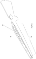
- FIG. 1 is a side view of a firearm constructed according to the present invention
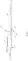
- FIG. 2 is a sectional perspective view of the firearm shown in FIG. 1 ;
- FIG. 3 is a sectional rear view of a center support rail and side rails for the firearm shown in FIG. 1 ;
- FIG. 4 is a sectional side view of the firearm shown in FIG. 1 ;
- FIG. 5 is a perspective view of the center support rail and side rails show in 30 FIG. 3 ;
- FIG. 6 is a side view of a harmonic tuner assembly constructed according to the present invention.
- FIG. 1 there is shown a side view of a firearm, generally designated as 10 , constructed according to the present inventions.
- the firearm includes a shoulder 26 for resting the firearm against the operator's body.
- the firearm also includes a handle 24 where the operator is able to grasp the firearm with one hand or rest the firearm against the forearm.
- the firearm also includes a forestock 22 about midway the length of the firearm. The operator may grasp hold of the forestock 22 while in operation.
- the firearm also includes a barreled action 12 , used for initiating the firing of a projectile and for aiming a projectile.
- the barreled action 12 is made of two parts, the receiver 13 whereby the ammunition feeding system is located and the barrel 11 where projectiles travel through after firing.
- FIG. 2 is a perspective view of the improved firearm 10 .
- FIG. 2 shows one aperture 40 for receiving a fastener and an open slot 44 for receiving an ammunition feeding system.
- the ammunition feeding system is inserted through the bottom of the firearm and is connected to the barrel action 12 .
- the barreled action 12 rests on the upper portion of the firearm and is secured to the ammunition feeding system, thereby anchoring both items into place.
- the barreled action 12 may then be further secured by a fastener inserted through aperture 40 .
- FIG. 3 shows a rear sectional view of the support for the improved firearm.
- the support is generally designated as 16 .
- the support 16 is made of a center support rail 30 , which runs about the length of the forestock 22 of the firearm.
- the center support rail 30 as shown in FIG. 3 also has a pair of side rails 32 attached on both sides. These pair of side rails 32 may run the length of the receiver 13 .
- the receiver 13 rests against the side rails and the center support rail thereby forming a 3-point continuous contact along most of the length of receiver 13 .
- the distal ends 46 of the side rails 32 are sloped inward.
- FIG. 4 shows a cross sectional side view of the improved firearm assembly.
- an aperture 42 at the rearward portion of the barreled action attaches a 5 receiver 13 to the center support rail 30 .
- a recoil lug 38 is placed to secure the barreled action and receiver against the center support rail 30 and prevent recoil vibration of the gun.
- the recoil lug 38 is then secured against a shoulder 34 for receiving the recoil lug by the use of a wedge mechanism 36 .
- Another aperture 40 may be included to secure the receiver 13 to the center support rail 30 .
- FIG. 5 shows a perspective view of the support 16 .
- the support 16 includes a center support rail 30 .
- the center support rail is attached to a pair of side rails 32 .
- FIG. 5 also shows an aperture 40 for receiving a fastener to secure the receiver to the center support rail.
- FIG. 5 also shows another aperture 42 also for securing a receiver to the center support rail and an open slot 44 for receiving the ammunition feeding system and may further include at least one aperture 48 for receiving a fastener for attaching at least one recoil lug 38 to the center support rail 30 .
- FIG. 6 shows a side sectional view of a harmonic tuner assembly for the barrel designated as 20 .
- the harmonic tuner 20 is located in the forestock 22 and is secured against the barrel 11 .
- the barreled action 12 is secured to the support 16 of the firearm 20 by a series of fasteners and the recoil lug 38 .
- the support 16 is then secured to the forestock IO with the use of a fastener.
- the user initiates firing of a projectile through the use of a trigger and firing assembly, which strikes the charged projectile and initiates the powder charge.
- the user may then adjust the harmonic tuner assembly 20 to reach optimal firing conditions.
- the harmonic tuner assembly may be adjusted by increasing the force mechanism on the assembly or by moving the assembly along the length of the barrel 11 .
- a user could utilize only the center support rail or only the side rails instead of those elements working in conjunction with one another.
- the user could elect to use a non-continuous support that is fragmented and moveable in the forestock if desired.
- the user may elect to have side rails that run the entire length of the forestock instead of the length of the receiver.
- the user may elect to have a stock made of an alternate material, including but not limited to wood, where the rail may be permanently affixed to the stock.
Landscapes
- Engineering & Computer Science (AREA)
- General Engineering & Computer Science (AREA)
- Toys (AREA)
- Aiming, Guidance, Guns With A Light Source, Armor, Camouflage, And Targets (AREA)
- Golf Clubs (AREA)
Abstract
Description
Claims (18)
Priority Applications (1)
| Application Number | Priority Date | Filing Date | Title |
|---|---|---|---|
| US16/121,344 US10690440B2 (en) | 2007-07-31 | 2018-09-04 | Stock for a firearm |
Applications Claiming Priority (4)
| Application Number | Priority Date | Filing Date | Title |
|---|---|---|---|
| US83141707A | 2007-07-31 | 2007-07-31 | |
| US201514823938A | 2015-08-11 | 2015-08-11 | |
| US15/419,820 US10066898B1 (en) | 2007-07-31 | 2017-01-30 | Stock for a firearm |
| US16/121,344 US10690440B2 (en) | 2007-07-31 | 2018-09-04 | Stock for a firearm |
Related Parent Applications (1)
| Application Number | Title | Priority Date | Filing Date |
|---|---|---|---|
| US15/419,820 Continuation US10066898B1 (en) | 2007-07-31 | 2017-01-30 | Stock for a firearm |
Publications (2)
| Publication Number | Publication Date |
|---|---|
| US20190056194A1 US20190056194A1 (en) | 2019-02-21 |
| US10690440B2 true US10690440B2 (en) | 2020-06-23 |
Family
ID=63295190
Family Applications (2)
| Application Number | Title | Priority Date | Filing Date |
|---|---|---|---|
| US15/419,820 Active US10066898B1 (en) | 2007-07-31 | 2017-01-30 | Stock for a firearm |
| US16/121,344 Active US10690440B2 (en) | 2007-07-31 | 2018-09-04 | Stock for a firearm |
Family Applications Before (1)
| Application Number | Title | Priority Date | Filing Date |
|---|---|---|---|
| US15/419,820 Active US10066898B1 (en) | 2007-07-31 | 2017-01-30 | Stock for a firearm |
Country Status (1)
| Country | Link |
|---|---|
| US (2) | US10066898B1 (en) |
Cited By (3)
| Publication number | Priority date | Publication date | Assignee | Title |
|---|---|---|---|---|
| WO2021040887A2 (en) | 2019-07-02 | 2021-03-04 | Savage Arms, Inc. | Rifle with straight pull bolt action |
| US12359887B2 (en) | 2016-12-29 | 2025-07-15 | Blackstone Firearms, Llc | Firearm barrel with outer sleeve |
| US12429299B1 (en) | 2016-12-29 | 2025-09-30 | Blackstone Firearms, Llc | Firearm barrel with non-metal outer sleeve |
Families Citing this family (2)
| Publication number | Priority date | Publication date | Assignee | Title |
|---|---|---|---|---|
| US20230046241A1 (en) * | 2021-08-11 | 2023-02-16 | Weatherby, Inc. | Reinforced rifle stock |
| US20250075999A1 (en) * | 2023-08-29 | 2025-03-06 | Gunwerks Llc | Carbon fiber gun stock and methods of fabrication |
Citations (37)
| Publication number | Priority date | Publication date | Assignee | Title |
|---|---|---|---|---|
| US1307469A (en) | 1919-06-24 | Hand-grip fob | ||
| US1768372A (en) | 1929-09-30 | 1930-06-24 | Charles S Powell | Fore end for shotguns |
| US2140945A (en) | 1936-12-04 | 1938-12-20 | Colt S Mfg Co | Firearm balancer |
| US2205982A (en) | 1939-05-11 | 1940-06-25 | Western Cartridge Co | Stock-and-barrel assembly for firearms |
| US2302699A (en) | 1939-10-30 | 1942-11-24 | Paul W Klipsch | Firearm vibration control |
| US2372568A (en) | 1943-11-20 | 1945-03-27 | Jesse M Grigg | Gun |
| US2479594A (en) | 1948-07-09 | 1949-08-23 | Samuel J Yasho | Barrel support means for firearms |
| US2497861A (en) | 1947-09-19 | 1950-02-21 | Jr Edwards Brown | Mechanism for bedding a firearm barrel in a stock |
| US2585195A (en) | 1949-01-08 | 1952-02-12 | Remington Arms Co Inc | Breech closing construction for firearms |
| US2589912A (en) | 1949-08-09 | 1952-03-18 | Leon S Weld | Barrel bedding device for rifles |
| US2610426A (en) | 1949-02-16 | 1952-09-16 | Olin Ind Inc | Takedown mechanism for firearms |
| US2749641A (en) | 1951-08-14 | 1956-06-12 | Wilbur J Hauck | Falling block single shot breech action |
| US2752714A (en) | 1953-01-23 | 1956-07-03 | Louis F Landwehr | Stabilizer for firearms |
| US2841909A (en) | 1954-07-12 | 1958-07-08 | Olin Mathieson | Constant torque-type stress appliance for firearm barrels |
| US2845737A (en) | 1955-10-10 | 1958-08-05 | Michael G Hoyer | Mechanical recoil compensator |
| US2921396A (en) | 1959-02-06 | 1960-01-19 | High Standard Mfg Corp | Barrel weight and mount assembly for firearms |
| US3060612A (en) | 1958-10-13 | 1962-10-30 | Brown Edwards | Means for imposing a predetermined force between adjacent members |
| US3206885A (en) | 1963-10-01 | 1965-09-21 | Dye Garnett Jethro | Firearm with metal bearing member and plastic material between receiver and stock |
| US3340641A (en) | 1964-12-15 | 1967-09-12 | Heli Pic Inc | Method and means for improving the accuracy of firearms by reducing barrel vibrations |
| US3350807A (en) | 1966-05-26 | 1967-11-07 | James H Monroe | Method and means of improving firearm accuracy |
| US3604136A (en) | 1968-09-05 | 1971-09-14 | Jesse B Edwards | Shotgun counterbalance |
| US3830003A (en) | 1970-04-16 | 1974-08-20 | J Clerke | Floated barrel rifle with metal stock for improved barrel action bedding |
| US4057924A (en) | 1976-11-04 | 1977-11-15 | Joseph Robert P | Rifle barrel stabilizer |
| US4211146A (en) | 1977-12-28 | 1980-07-08 | Bradley Richard L | Rifle gun barrel |
| US4282671A (en) | 1979-02-28 | 1981-08-11 | Olin Corporation | Bolt-on fore stock |
| US4385464A (en) | 1980-09-15 | 1983-05-31 | Casull Richard J | Mounting of barrell and action to rifle stock |
| US4674216A (en) | 1985-12-04 | 1987-06-23 | Sturm, Ruger & Company, Inc. | Synthetic material rifle stock with panel inserts |
| US5020260A (en) | 1989-12-29 | 1991-06-04 | H-S Precision, Inc. | Take-down rifle |
| US5423145A (en) | 1994-09-16 | 1995-06-13 | Nasset; James L. | Rifle-barrel harmonic vibration tuning device |
| US5864978A (en) | 1996-11-15 | 1999-02-02 | T2 Stocks, Inc. | Solid synthetic weapon stocks |
| US6256921B1 (en) | 1999-01-29 | 2001-07-10 | Ra Brands, L.L.C. | One-piece synthetic undercarriage |
| US6301817B1 (en) | 1996-11-14 | 2001-10-16 | Aaron G. Hogue | Long gun stock |
| US6487805B1 (en) | 2000-05-19 | 2002-12-03 | Armalite, Inc. | Firearm assembly |
| US6889462B1 (en) | 2003-09-05 | 2005-05-10 | Robert M. Bayer | Harmonic stabilizer system for rifle barrel and a rifle equipped therewith |
| US20050115135A1 (en) * | 2003-08-11 | 2005-06-02 | Accurate Innovations, L.L.C. | Gunstock |
| US20050235545A1 (en) * | 2003-08-11 | 2005-10-27 | Accurate Innovations, L.L.C. | Gunstock |
| US7665240B1 (en) * | 2006-02-09 | 2010-02-23 | Blackhawk Industries Product Group Unlimited Llc | Modular system rifle stock |
-
2017
- 2017-01-30 US US15/419,820 patent/US10066898B1/en active Active
-
2018
- 2018-09-04 US US16/121,344 patent/US10690440B2/en active Active
Patent Citations (39)
| Publication number | Priority date | Publication date | Assignee | Title |
|---|---|---|---|---|
| US1307469A (en) | 1919-06-24 | Hand-grip fob | ||
| US1768372A (en) | 1929-09-30 | 1930-06-24 | Charles S Powell | Fore end for shotguns |
| US2140945A (en) | 1936-12-04 | 1938-12-20 | Colt S Mfg Co | Firearm balancer |
| US2205982A (en) | 1939-05-11 | 1940-06-25 | Western Cartridge Co | Stock-and-barrel assembly for firearms |
| US2302699A (en) | 1939-10-30 | 1942-11-24 | Paul W Klipsch | Firearm vibration control |
| US2372568A (en) | 1943-11-20 | 1945-03-27 | Jesse M Grigg | Gun |
| US2497861A (en) | 1947-09-19 | 1950-02-21 | Jr Edwards Brown | Mechanism for bedding a firearm barrel in a stock |
| US2479594A (en) | 1948-07-09 | 1949-08-23 | Samuel J Yasho | Barrel support means for firearms |
| US2585195A (en) | 1949-01-08 | 1952-02-12 | Remington Arms Co Inc | Breech closing construction for firearms |
| US2610426A (en) | 1949-02-16 | 1952-09-16 | Olin Ind Inc | Takedown mechanism for firearms |
| US2589912A (en) | 1949-08-09 | 1952-03-18 | Leon S Weld | Barrel bedding device for rifles |
| US2749641A (en) | 1951-08-14 | 1956-06-12 | Wilbur J Hauck | Falling block single shot breech action |
| US2752714A (en) | 1953-01-23 | 1956-07-03 | Louis F Landwehr | Stabilizer for firearms |
| US2841909A (en) | 1954-07-12 | 1958-07-08 | Olin Mathieson | Constant torque-type stress appliance for firearm barrels |
| US2845737A (en) | 1955-10-10 | 1958-08-05 | Michael G Hoyer | Mechanical recoil compensator |
| US3060612A (en) | 1958-10-13 | 1962-10-30 | Brown Edwards | Means for imposing a predetermined force between adjacent members |
| US2921396A (en) | 1959-02-06 | 1960-01-19 | High Standard Mfg Corp | Barrel weight and mount assembly for firearms |
| US3206885A (en) | 1963-10-01 | 1965-09-21 | Dye Garnett Jethro | Firearm with metal bearing member and plastic material between receiver and stock |
| US3340641A (en) | 1964-12-15 | 1967-09-12 | Heli Pic Inc | Method and means for improving the accuracy of firearms by reducing barrel vibrations |
| US3350807A (en) | 1966-05-26 | 1967-11-07 | James H Monroe | Method and means of improving firearm accuracy |
| US3604136A (en) | 1968-09-05 | 1971-09-14 | Jesse B Edwards | Shotgun counterbalance |
| US3830003A (en) | 1970-04-16 | 1974-08-20 | J Clerke | Floated barrel rifle with metal stock for improved barrel action bedding |
| US4057924A (en) | 1976-11-04 | 1977-11-15 | Joseph Robert P | Rifle barrel stabilizer |
| US4211146A (en) | 1977-12-28 | 1980-07-08 | Bradley Richard L | Rifle gun barrel |
| US4282671A (en) | 1979-02-28 | 1981-08-11 | Olin Corporation | Bolt-on fore stock |
| US4385464A (en) | 1980-09-15 | 1983-05-31 | Casull Richard J | Mounting of barrell and action to rifle stock |
| US4674216A (en) | 1985-12-04 | 1987-06-23 | Sturm, Ruger & Company, Inc. | Synthetic material rifle stock with panel inserts |
| US5020260A (en) | 1989-12-29 | 1991-06-04 | H-S Precision, Inc. | Take-down rifle |
| US5423145A (en) | 1994-09-16 | 1995-06-13 | Nasset; James L. | Rifle-barrel harmonic vibration tuning device |
| US6301817B1 (en) | 1996-11-14 | 2001-10-16 | Aaron G. Hogue | Long gun stock |
| US5864978A (en) | 1996-11-15 | 1999-02-02 | T2 Stocks, Inc. | Solid synthetic weapon stocks |
| US6256921B1 (en) | 1999-01-29 | 2001-07-10 | Ra Brands, L.L.C. | One-piece synthetic undercarriage |
| US6427372B1 (en) | 1999-01-29 | 2002-08-06 | Ra Brands, Llc | One-piece synthetic undercarriage |
| US6487805B1 (en) | 2000-05-19 | 2002-12-03 | Armalite, Inc. | Firearm assembly |
| US6637142B1 (en) | 2000-05-19 | 2003-10-28 | Armalite, Inc. | Firearm assembly |
| US20050115135A1 (en) * | 2003-08-11 | 2005-06-02 | Accurate Innovations, L.L.C. | Gunstock |
| US20050235545A1 (en) * | 2003-08-11 | 2005-10-27 | Accurate Innovations, L.L.C. | Gunstock |
| US6889462B1 (en) | 2003-09-05 | 2005-05-10 | Robert M. Bayer | Harmonic stabilizer system for rifle barrel and a rifle equipped therewith |
| US7665240B1 (en) * | 2006-02-09 | 2010-02-23 | Blackhawk Industries Product Group Unlimited Llc | Modular system rifle stock |
Cited By (5)
| Publication number | Priority date | Publication date | Assignee | Title |
|---|---|---|---|---|
| US12359887B2 (en) | 2016-12-29 | 2025-07-15 | Blackstone Firearms, Llc | Firearm barrel with outer sleeve |
| US12429299B1 (en) | 2016-12-29 | 2025-09-30 | Blackstone Firearms, Llc | Firearm barrel with non-metal outer sleeve |
| WO2021040887A2 (en) | 2019-07-02 | 2021-03-04 | Savage Arms, Inc. | Rifle with straight pull bolt action |
| DE112020003203T5 (en) | 2019-07-02 | 2022-03-24 | Savage Arms, Inc. | Straight-pull bolt-action rifle |
| US12031788B2 (en) | 2019-07-02 | 2024-07-09 | Savage Arms, Inc. | Rifle with straight pull bolt action |
Also Published As
| Publication number | Publication date |
|---|---|
| US20190056194A1 (en) | 2019-02-21 |
| US10066898B1 (en) | 2018-09-04 |
Similar Documents
| Publication | Publication Date | Title |
|---|---|---|
| US10690440B2 (en) | Stock for a firearm | |
| US11796274B2 (en) | Recoil-reducing firearm shooting rest having tank | |
| US9702653B2 (en) | Firearm shooting rest | |
| US9091505B1 (en) | Solid chassis rifle | |
| US7823313B2 (en) | Gunstock | |
| US8769854B1 (en) | Solid chassis rifle | |
| US9074839B2 (en) | Interchangeable buttstock system for rifles | |
| US20100229444A1 (en) | Gunstock | |
| US8397617B2 (en) | Adapter for converting a magazine-fed firearm to use linked ammunition | |
| US9341442B1 (en) | Knife mount for a firearm | |
| US8117954B1 (en) | Firearm modification kit | |
| US11035646B2 (en) | Grenade launcher with modular interface | |
| US10648769B2 (en) | Handgun grip module with a reinforcing bracket | |
| US9618285B2 (en) | Removable magazine for a rifle | |
| US20180017353A1 (en) | Composite recoil absorber insert for firearm stock | |
| US11867477B2 (en) | Assault rifle conversion kit—folding gun stock assembly | |
| US11796266B2 (en) | Upper receiver for a firearm | |
| JP7155252B2 (en) | machine gun | |
| US10386145B2 (en) | Double barrel adjustment assembly | |
| US10077958B2 (en) | Recoil spring for a firearm | |
| RU2520175C2 (en) | Gun stock | |
| US11585633B2 (en) | Handgun brace for mitigating muzzle jump recoil and promoting proper handgun grip positioning | |
| US12435943B2 (en) | Bullpup-type gun with barrel positioned at bottom | |
| EP2360445B1 (en) | A recoil absorbing assembly for automatic weapons | |
| PL203662B1 (en) | Bolt-action large-caliber sniper rifle |
Legal Events
| Date | Code | Title | Description |
|---|---|---|---|
| FEPP | Fee payment procedure |
Free format text: ENTITY STATUS SET TO UNDISCOUNTED (ORIGINAL EVENT CODE: BIG.); ENTITY STATUS OF PATENT OWNER: SMALL ENTITY |
|
| STPP | Information on status: patent application and granting procedure in general |
Free format text: DOCKETED NEW CASE - READY FOR EXAMINATION |
|
| AS | Assignment |
Owner name: WELLS FARGO BANK, NATIONAL ASSOCIATION, AS ADMINIS Free format text: TERM LOAN INTELLECTUAL PROPERTY SECURITY AGREEMENT SUPPLEMENT;ASSIGNORS:BELL SPORTS, INC.;BUSHNELL HOLDINGS, INC.;BUSHNELL INC.;AND OTHERS;REEL/FRAME:048413/0051 Effective date: 20190222 Owner name: WELLS FARGO BANK, NATIONAL ASSOCIATION, AS ADMINISTRATIVE AGENT, CALIFORNIA Free format text: TERM LOAN INTELLECTUAL PROPERTY SECURITY AGREEMENT SUPPLEMENT;ASSIGNORS:BELL SPORTS, INC.;BUSHNELL HOLDINGS, INC.;BUSHNELL INC.;AND OTHERS;REEL/FRAME:048413/0051 Effective date: 20190222 |
|
| AS | Assignment |
Owner name: WELLS FARGO BANK, NATIONAL ASSOCIATION, AS ADMINIS Free format text: ABL INTELLECTUAL PROPERTY SECURITY AGREEMENT SUPPLEMENT;ASSIGNORS:BELL SPORTS, INC.;BUSHNELL HOLDINGS, INC.;BUSHNELL INC.;AND OTHERS;REEL/FRAME:048421/0556 Effective date: 20190222 Owner name: WELLS FARGO BANK, NATIONAL ASSOCIATION, AS ADMINISTRATIVE AGENT, CALIFORNIA Free format text: ABL INTELLECTUAL PROPERTY SECURITY AGREEMENT SUPPLEMENT;ASSIGNORS:BELL SPORTS, INC.;BUSHNELL HOLDINGS, INC.;BUSHNELL INC.;AND OTHERS;REEL/FRAME:048421/0556 Effective date: 20190222 |
|
| AS | Assignment |
Owner name: GACP FINANCE CO., LLC, CALIFORNIA Free format text: SECURITY INTEREST;ASSIGNORS:BELL SPORTS, INC.;BUSHNELL HOLDINGS, INC.;BUSHNELL INC.;AND OTHERS;REEL/FRAME:049515/0590 Effective date: 20190312 |
|
| AS | Assignment |
Owner name: SAVAGE ARMS, INC., MASSACHUSETTS Free format text: ASSIGNMENT OF ASSIGNORS INTEREST;ASSIGNORS:COBURN, RONALD;WARBURTON, SCOTT;REEL/FRAME:048795/0766 Effective date: 20071009 |
|
| AS | Assignment |
Owner name: SAVAGE ARMS, INC., MASSACHUSETTS Free format text: PARTIAL RELEASE OF INTELLECTUAL PROPERTY SECURITY INTERESTS (ABL);ASSIGNOR:WELLS FARGO BANK, NATIONAL ASSOCIATION, AS ADMINISTRATIVE AGENT;REEL/FRAME:049679/0961 Effective date: 20190705 Owner name: CALIBER COMPANY, MASSACHUSETTS Free format text: PARTIAL RELEASE OF INTELLECTUAL PROPERTY SECURITY INTERESTS (TERM LOAN);ASSIGNOR:WELLS FARGO BANK, NATIONAL ASSOCIATION, AS ADMINISTRATIVE AGENT;REEL/FRAME:049680/0030 Effective date: 20190705 Owner name: SAVAGE SPORTS HOLDINGS, INC., MASSACHUSETTS Free format text: PARTIAL RELEASE OF INTELLECTUAL PROPERTY SECURITY INTERESTS (TERM LOAN);ASSIGNOR:WELLS FARGO BANK, NATIONAL ASSOCIATION, AS ADMINISTRATIVE AGENT;REEL/FRAME:049680/0030 Effective date: 20190705 Owner name: SAVAGE RANGE SYSTEMS, INC., MASSACHUSETTS Free format text: PARTIAL RELEASE OF INTELLECTUAL PROPERTY SECURITY INTERESTS (TERM LOAN);ASSIGNOR:WELLS FARGO BANK, NATIONAL ASSOCIATION, AS ADMINISTRATIVE AGENT;REEL/FRAME:049680/0030 Effective date: 20190705 Owner name: SAVAGE SPORTS HOLDINGS, INC., MASSACHUSETTS Free format text: PARTIAL RELEASE OF INTELLECTUAL PROPERTY SECURITY INTERESTS (ABL);ASSIGNOR:WELLS FARGO BANK, NATIONAL ASSOCIATION, AS ADMINISTRATIVE AGENT;REEL/FRAME:049679/0961 Effective date: 20190705 Owner name: CALIBER COMPANY, MASSACHUSETTS Free format text: PARTIAL RELEASE OF INTELLECTUAL PROPERTY SECURITY INTERESTS (ABL);ASSIGNOR:WELLS FARGO BANK, NATIONAL ASSOCIATION, AS ADMINISTRATIVE AGENT;REEL/FRAME:049679/0961 Effective date: 20190705 Owner name: SAVAGE RANGE SYSTEMS, INC., MASSACHUSETTS Free format text: PARTIAL RELEASE OF INTELLECTUAL PROPERTY SECURITY INTERESTS (ABL);ASSIGNOR:WELLS FARGO BANK, NATIONAL ASSOCIATION, AS ADMINISTRATIVE AGENT;REEL/FRAME:049679/0961 Effective date: 20190705 Owner name: SAVAGE ARMS, INC., MASSACHUSETTS Free format text: PARTIAL RELEASE OF INTELLECTUAL PROPERTY SECURITY INTERESTS (TERM LOAN);ASSIGNOR:WELLS FARGO BANK, NATIONAL ASSOCIATION, AS ADMINISTRATIVE AGENT;REEL/FRAME:049680/0030 Effective date: 20190705 Owner name: SAVAGE SPORTS CORPORATION, MASSACHUSETTS Free format text: PARTIAL RELEASE OF INTELLECTUAL PROPERTY SECURITY INTERESTS (TERM LOAN);ASSIGNOR:WELLS FARGO BANK, NATIONAL ASSOCIATION, AS ADMINISTRATIVE AGENT;REEL/FRAME:049680/0030 Effective date: 20190705 Owner name: SAVAGE SPORTS CORPORATION, MASSACHUSETTS Free format text: PARTIAL RELEASE OF INTELLECTUAL PROPERTY SECURITY INTERESTS (ABL);ASSIGNOR:WELLS FARGO BANK, NATIONAL ASSOCIATION, AS ADMINISTRATIVE AGENT;REEL/FRAME:049679/0961 Effective date: 20190705 |
|
| AS | Assignment |
Owner name: SAVAGE SPORTS HOLDINGS, INC., MINNESOTA Free format text: RELEASE BY SECURED PARTY;ASSIGNOR:GACP FINANCE CO., LLC;REEL/FRAME:049691/0535 Effective date: 20190705 Owner name: CALIBER COMPANY, MINNESOTA Free format text: RELEASE BY SECURED PARTY;ASSIGNOR:GACP FINANCE CO., LLC;REEL/FRAME:049691/0535 Effective date: 20190705 Owner name: SAVAGE ARMS, INC., MASSACHUSETTS Free format text: RELEASE BY SECURED PARTY;ASSIGNOR:GACP FINANCE CO., LLC;REEL/FRAME:049691/0535 Effective date: 20190705 Owner name: SAVAGE RANGE SYSTEMS, INC., MASSACHUSETTS Free format text: RELEASE BY SECURED PARTY;ASSIGNOR:GACP FINANCE CO., LLC;REEL/FRAME:049691/0535 Effective date: 20190705 Owner name: SAVAGE SPORTS CORPORATION, MINNESOTA Free format text: RELEASE BY SECURED PARTY;ASSIGNOR:GACP FINANCE CO., LLC;REEL/FRAME:049691/0535 Effective date: 20190705 |
|
| AS | Assignment |
Owner name: MGG INVESTMENT GROUP, LP, AS COLLATERAL AGENT, NEW Free format text: ASSIGNMEMT FOR SECURITY -- PATENTS;ASSIGNORS:SAVAGE RANGE SYSTEMS, INC.;SAVAGE ARMS, INC.;REEL/FRAME:049705/0914 Effective date: 20190705 Owner name: MGG INVESTMENT GROUP, LP, AS COLLATERAL AGENT, NEW YORK Free format text: ASSIGNMEMT FOR SECURITY -- PATENTS;ASSIGNORS:SAVAGE RANGE SYSTEMS, INC.;SAVAGE ARMS, INC.;REEL/FRAME:049705/0914 Effective date: 20190705 |
|
| STPP | Information on status: patent application and granting procedure in general |
Free format text: NON FINAL ACTION MAILED |
|
| AS | Assignment |
Owner name: C PREME LIMITED LLC, CALIFORNIA Free format text: RELEASE OF SECURITY AGREEMENT;ASSIGNOR:GACP FINANCE CO., LLC, AS ADMINISTRATIVE AGENT;REEL/FRAME:050829/0344 Effective date: 20191023 Owner name: NIGHT OPTICS USA, INC., CALIFORNIA Free format text: RELEASE OF SECURITY AGREEMENT;ASSIGNOR:GACP FINANCE CO., LLC, AS ADMINISTRATIVE AGENT;REEL/FRAME:050829/0344 Effective date: 20191023 Owner name: BUSHNELL INC., KANSAS Free format text: RELEASE OF SECURITY AGREEMENT;ASSIGNOR:GACP FINANCE CO., LLC, AS ADMINISTRATIVE AGENT;REEL/FRAME:050829/0344 Effective date: 20191023 Owner name: BEE STINGER, LLC, UTAH Free format text: RELEASE OF SECURITY AGREEMENT;ASSIGNOR:GACP FINANCE CO., LLC, AS ADMINISTRATIVE AGENT;REEL/FRAME:050829/0344 Effective date: 20191023 Owner name: VISTA OUTDOOR OPERATIONS LLC, MINNESOTA Free format text: RELEASE OF SECURITY AGREEMENT;ASSIGNOR:GACP FINANCE CO., LLC, AS ADMINISTRATIVE AGENT;REEL/FRAME:050829/0344 Effective date: 20191023 Owner name: MICHAELS OF OREGON CO., KANSAS Free format text: RELEASE OF SECURITY AGREEMENT;ASSIGNOR:GACP FINANCE CO., LLC, AS ADMINISTRATIVE AGENT;REEL/FRAME:050829/0344 Effective date: 20191023 Owner name: GOLD TIP, LLC, UTAH Free format text: RELEASE OF SECURITY AGREEMENT;ASSIGNOR:GACP FINANCE CO., LLC, AS ADMINISTRATIVE AGENT;REEL/FRAME:050829/0344 Effective date: 20191023 Owner name: STONEY POINT PRODUCTS, INC., KANSAS Free format text: RELEASE OF SECURITY AGREEMENT;ASSIGNOR:GACP FINANCE CO., LLC, AS ADMINISTRATIVE AGENT;REEL/FRAME:050829/0344 Effective date: 20191023 Owner name: CAMELBAK PRODUCTS, LLC, CALIFORNIA Free format text: RELEASE OF SECURITY AGREEMENT;ASSIGNOR:GACP FINANCE CO., LLC, AS ADMINISTRATIVE AGENT;REEL/FRAME:050829/0344 Effective date: 20191023 Owner name: BUSHNELL HOLDINGS, INC., KANSAS Free format text: RELEASE OF SECURITY AGREEMENT;ASSIGNOR:GACP FINANCE CO., LLC, AS ADMINISTRATIVE AGENT;REEL/FRAME:050829/0344 Effective date: 20191023 Owner name: VISTA OUTDOOR INC., MINNESOTA Free format text: RELEASE OF SECURITY AGREEMENT;ASSIGNOR:GACP FINANCE CO., LLC, AS ADMINISTRATIVE AGENT;REEL/FRAME:050829/0344 Effective date: 20191023 Owner name: MILLETT INDUSTRIES, KANSAS Free format text: RELEASE OF SECURITY AGREEMENT;ASSIGNOR:GACP FINANCE CO., LLC, AS ADMINISTRATIVE AGENT;REEL/FRAME:050829/0344 Effective date: 20191023 Owner name: EAGLE INDUSTRIES UNLIMITED, INC., VIRGINIA Free format text: RELEASE OF SECURITY AGREEMENT;ASSIGNOR:GACP FINANCE CO., LLC, AS ADMINISTRATIVE AGENT;REEL/FRAME:050829/0344 Effective date: 20191023 Owner name: FEDERAL CARTRIDGE COMPANY, MINNESOTA Free format text: RELEASE OF SECURITY AGREEMENT;ASSIGNOR:GACP FINANCE CO., LLC, AS ADMINISTRATIVE AGENT;REEL/FRAME:050829/0344 Effective date: 20191023 Owner name: LOGAN OUTDOOR PRODUCTS, LLC, UTAH Free format text: RELEASE OF SECURITY AGREEMENT;ASSIGNOR:GACP FINANCE CO., LLC, AS ADMINISTRATIVE AGENT;REEL/FRAME:050829/0344 Effective date: 20191023 Owner name: NORTHSTAR OUTDOORS, LLC (FKA JIMMY STYKS LLC), KAN Free format text: RELEASE OF SECURITY AGREEMENT;ASSIGNOR:GACP FINANCE CO., LLC, AS ADMINISTRATIVE AGENT;REEL/FRAME:050829/0344 Effective date: 20191023 Owner name: BELL SPORTS, INC., CALIFORNIA Free format text: RELEASE OF SECURITY AGREEMENT;ASSIGNOR:GACP FINANCE CO., LLC, AS ADMINISTRATIVE AGENT;REEL/FRAME:050829/0344 Effective date: 20191023 Owner name: NORTHSTAR OUTDOORS, LLC (FKA JIMMY STYKS LLC), KANSAS Free format text: RELEASE OF SECURITY AGREEMENT;ASSIGNOR:GACP FINANCE CO., LLC, AS ADMINISTRATIVE AGENT;REEL/FRAME:050829/0344 Effective date: 20191023 |
|
| FEPP | Fee payment procedure |
Free format text: ENTITY STATUS SET TO SMALL (ORIGINAL EVENT CODE: SMAL); ENTITY STATUS OF PATENT OWNER: SMALL ENTITY |
|
| STPP | Information on status: patent application and granting procedure in general |
Free format text: RESPONSE TO NON-FINAL OFFICE ACTION ENTERED AND FORWARDED TO EXAMINER |
|
| STPP | Information on status: patent application and granting procedure in general |
Free format text: NOTICE OF ALLOWANCE MAILED -- APPLICATION RECEIVED IN OFFICE OF PUBLICATIONS |
|
| STPP | Information on status: patent application and granting procedure in general |
Free format text: PUBLICATIONS -- ISSUE FEE PAYMENT VERIFIED |
|
| STCF | Information on status: patent grant |
Free format text: PATENTED CASE |
|
| AS | Assignment |
Owner name: REGIONS BANK, AS AGENT, GEORGIA Free format text: SECURITY INTEREST;ASSIGNORS:SAVAGE ARMS, INC.;SAVAGE RANGE SYSTEMS, INC.;REEL/FRAME:054148/0787 Effective date: 20201023 |
|
| AS | Assignment |
Owner name: SAVAGE SPORTS CORPORATION, MASSACHUSETTS Free format text: RELEASE BY SECURED PARTY;ASSIGNOR:MGG INVESTMENT GROUP LP;REEL/FRAME:054207/0853 Effective date: 20201023 Owner name: SAVAGE ARMS, INC., MASSACHUSETTS Free format text: RELEASE BY SECURED PARTY;ASSIGNOR:MGG INVESTMENT GROUP LP;REEL/FRAME:054207/0853 Effective date: 20201023 |
|
| AS | Assignment |
Owner name: REGIONS BANK, GEORGIA Free format text: SECURITY INTEREST;ASSIGNORS:SAVAGE ARMS, INC.;SAVAGE RANGE SYSTEMS, INC.;REEL/FRAME:064959/0511 Effective date: 20230915 |
|
| MAFP | Maintenance fee payment |
Free format text: PAYMENT OF MAINTENANCE FEE, 4TH YR, SMALL ENTITY (ORIGINAL EVENT CODE: M2551); ENTITY STATUS OF PATENT OWNER: SMALL ENTITY Year of fee payment: 4 |