EP2360396A1 - Continuously variable transmission system - Google Patents
Continuously variable transmission system Download PDFInfo
- Publication number
- EP2360396A1 EP2360396A1 EP09832964A EP09832964A EP2360396A1 EP 2360396 A1 EP2360396 A1 EP 2360396A1 EP 09832964 A EP09832964 A EP 09832964A EP 09832964 A EP09832964 A EP 09832964A EP 2360396 A1 EP2360396 A1 EP 2360396A1
- Authority
- EP
- European Patent Office
- Prior art keywords
- subsystem
- continuously variable
- transmission system
- variable transmission
- accordance
- Prior art date
- Legal status (The legal status is an assumption and is not a legal conclusion. Google has not performed a legal analysis and makes no representation as to the accuracy of the status listed.)
- Granted
Links
Images



Classifications
-
- F—MECHANICAL ENGINEERING; LIGHTING; HEATING; WEAPONS; BLASTING
- F16—ENGINEERING ELEMENTS AND UNITS; GENERAL MEASURES FOR PRODUCING AND MAINTAINING EFFECTIVE FUNCTIONING OF MACHINES OR INSTALLATIONS; THERMAL INSULATION IN GENERAL
- F16H—GEARING
- F16H29/00—Gearings for conveying rotary motion with intermittently-driving members, e.g. with freewheel action
- F16H29/02—Gearings for conveying rotary motion with intermittently-driving members, e.g. with freewheel action between one of the shafts and an oscillating or reciprocating intermediate member, not rotating with either of the shafts
- F16H29/04—Gearings for conveying rotary motion with intermittently-driving members, e.g. with freewheel action between one of the shafts and an oscillating or reciprocating intermediate member, not rotating with either of the shafts in which the transmission ratio is changed by adjustment of a crank, an eccentric, a wobble-plate, or a cam, on one of the shafts
-
- F—MECHANICAL ENGINEERING; LIGHTING; HEATING; WEAPONS; BLASTING
- F16—ENGINEERING ELEMENTS AND UNITS; GENERAL MEASURES FOR PRODUCING AND MAINTAINING EFFECTIVE FUNCTIONING OF MACHINES OR INSTALLATIONS; THERMAL INSULATION IN GENERAL
- F16H—GEARING
- F16H29/00—Gearings for conveying rotary motion with intermittently-driving members, e.g. with freewheel action
- F16H29/12—Gearings for conveying rotary motion with intermittently-driving members, e.g. with freewheel action between rotary driving and driven members
- F16H29/14—Gearings for conveying rotary motion with intermittently-driving members, e.g. with freewheel action between rotary driving and driven members in which the transmission ratio is changed by adjustment of an otherwise stationary guide member for the intermittently-driving members
-
- F—MECHANICAL ENGINEERING; LIGHTING; HEATING; WEAPONS; BLASTING
- F16—ENGINEERING ELEMENTS AND UNITS; GENERAL MEASURES FOR PRODUCING AND MAINTAINING EFFECTIVE FUNCTIONING OF MACHINES OR INSTALLATIONS; THERMAL INSULATION IN GENERAL
- F16H—GEARING
- F16H33/00—Gearings based on repeated accumulation and delivery of energy
- F16H33/02—Rotary transmissions with mechanical accumulators, e.g. weights, springs, intermittently-connected flywheels
- F16H33/04—Gearings for conveying rotary motion with variable velocity ratio, in which self-regulation is sought
- F16H33/08—Gearings for conveying rotary motion with variable velocity ratio, in which self-regulation is sought based essentially on inertia
-
- Y—GENERAL TAGGING OF NEW TECHNOLOGICAL DEVELOPMENTS; GENERAL TAGGING OF CROSS-SECTIONAL TECHNOLOGIES SPANNING OVER SEVERAL SECTIONS OF THE IPC; TECHNICAL SUBJECTS COVERED BY FORMER USPC CROSS-REFERENCE ART COLLECTIONS [XRACs] AND DIGESTS
- Y10—TECHNICAL SUBJECTS COVERED BY FORMER USPC
- Y10T—TECHNICAL SUBJECTS COVERED BY FORMER US CLASSIFICATION
- Y10T74/00—Machine element or mechanism
- Y10T74/18—Mechanical movements
- Y10T74/1836—Rotary to rotary
-
- Y—GENERAL TAGGING OF NEW TECHNOLOGICAL DEVELOPMENTS; GENERAL TAGGING OF CROSS-SECTIONAL TECHNOLOGIES SPANNING OVER SEVERAL SECTIONS OF THE IPC; TECHNICAL SUBJECTS COVERED BY FORMER USPC CROSS-REFERENCE ART COLLECTIONS [XRACs] AND DIGESTS
- Y10—TECHNICAL SUBJECTS COVERED BY FORMER USPC
- Y10T—TECHNICAL SUBJECTS COVERED BY FORMER US CLASSIFICATION
- Y10T74/00—Machine element or mechanism
- Y10T74/18—Mechanical movements
- Y10T74/1836—Rotary to rotary
- Y10T74/18376—Crank, pitman, lever, and crank
Definitions
- This invention as expressed in the heading of this descriptive memory refers to a continuously variable transmission system with inertia regulation.
- It basically includes three subsystems that are related to each other, in a manner that the first of them provides an oscillating angular speed with variable amplitude, a second subsystem that includes an inertia mechanism and a third subsystem with movement rectification, which provides a single direction of rotation at its output.
- this is a continuously variable transmission system, it includes a limited number of transmission ratios within the possible gear ratio interval, while a continuous variation in the transmission ratio may be obtained.
- This invention has a direct application in the automobile industry, in any industrial application that requires a power transmission system as well as in any other application that requires torque regulation and changes in speed.
- Fixed ratio transmissions regardless of whether they are manual or automatic, include a discrete number of transmission ratios or gears.
- the transmission ratio between the input and output shafts may be progressively varied in a specific interval of possible ratios.
- the possibility of incorporating a limited number of transmission ratios provides an added parameter in order to optimize one or several variables of the vehicle. This way, with a specific variation in the transmission ratio, we can achieve conditions of high power, low consumption or a compromised ratio between both variables.
- the cinematic and dynamic types establishes two large groups of continuously variable transmissions, the cinematic and dynamic types.
- the progressive change in transmission ratio is carried out on a specific element, resulting in the transmission ratio being fixed at a specific value and requires acting upon the element once again in order to change it.
- the transmission ratio also depends on the external conditions to which the transmission is subjected to. This means that the transmission ratio will be determined by the cinematic characteristics as well as by variables such as the speed of the input shaft or the resistant torque exerted on the output shaft.
- the dynamic type continuously variable transmissions originate from the innovative work carried out by Hunt, which were published in GB patents 21,414 of 1912 and GB Patent 19,904 of 1913 , where an inertia type transmission system is described with the dynamic transmission principle but without a direct application like CVTs.
- the first documented continuously variable type dynamic transmission originates from the work of Constantinesco, described in his GB Patent 185,022 of 1922 and in his subsequent patents, which describe methods for improving the power transmission of the primary shafts of vehicles that operate using internal combustion engines.
- the torque is regulated using a pendulum or other inertia elements.
- the invention consists of a continuously variable transmission system with inertia regulation. Regulation is carried out using an inertia mechanism comprised of an epicyclic train that provides an additional degree of freedom. A specific mass is added to the element of the epicyclic train that includes this degree of freedom, which provides a dynamic character to the transmission and causes the train to act as a regulating element of the output shaft resistant torque.
- the complete system includes three different subsystems. A first subsystem that converts the signal provided by the drive system into an oscillating angular speed signal while it regulates the amplitude of said speed signal. This angular speed is used to drive the epicyclic train, which constitutes the second subsystem and is the inertia regulation mechanism for the transmission.
- the second subsystem provides an oscillating torque regulated signal.
- the oscillating signal at the output of the second subsystem must be rectified in the third subsystem.
- an angular speed signal in a single direction of rotation is finally obtained at the output shaft.
- a unidirectional torque capable of overcoming the resistant torque is applied at the transmission output shaft.
- the complete system provides a torque that is adapted to the operating conditions it is subjected to such as the angular speed of the transmission input shaft as well as the resistant torque at the output shaft. Therefore, the invention consists of a dynamic type continuously variable transmission system with an oscillating nature.
- This transmission system has a direct application in the automobile industry, in any industrial application that requires a power transmission system as well as in any other application that requires torque regulation and speed changes.
- the inertia element of the developed dynamic CVT is comprised of an epicyclic reducer with mass added to the crown. Said epicyclic reducer is inserted upside down into the CVT; therefore, the reducer's input shaft is connected to the satellite holder and the output shaft to the planet. Therefore, in an assembly of this type, the epicyclic reducer would be multiplying the input speed.
- the transmission regulation is based on the aforementioned property of the inertia element and the assembly.
- an angular speed law is used at the input shaft in the form of an oscillating signal, which is generated by means of a driving mechanism.
- the driving mechanism regulates the amplitude of said angular velocity.
- the signal at the planet also has an oscillating nature; therefore, a movement rectifying mechanism is required.
- the crown movement carries with it an additional degree of freedom.
- the adding of mass to the epicyclic train's crown allows said element to become a power regulation inertia mechanism.
- This regulation consists of cyclic power accumulations and cessions that allow the transmission to adapt to each one of the operating conditions it is subjected to.
- the complete transmission system includes three subsystems positioned in series.
- the purpose of the first subsystem S1 is to transform the signal originating from the drive system through shaft E1 ( FIGs. 1 and 2 ) into an angular oscillating speed signal with a variable amplitude at shaft E2 ( FIGs. 1 , 2 and 3 ); this shaft is the input to the second subsystem S2 ( FIG. 3 ).
- Bar B1 FIGs. 1 and 2 ) consists of a handle with a fixed radius R, which transmits the circular movement of its end to control gear EC ( FIGs. 1 and 2 ).
- This EC element is engaged with the control crown CC ( FIGs. 1 and 2 ) and spinning about the inner face of the crown, while said crown is fixed in its position as determined by the driving element EA ( FIGs.
- Said EA element uses a worm gear to drive the outer face of control crown CC in order to control its relative position with respect to the reference position, corresponding for example, to the minimum oscillating amplitude ( FIG. 7 ).
- Bar B2 ( FIGs. 1 and 2 ) is joined at a point P ( FIGs. 1 and 2 ) to the EC, with said point located at a radius R from the centre of the EC.
- the union at point P is carried out in such a manner to allow the relative turn between the EC elements and B2.
- the diameter of control gear EC is equal to the radius of the inner face of control crown CC.
- the hypocycloid curve generated by point P and therefore, the end of bar B2 at said point degenerates to a straight line that is described by the inner diameter of control crown CC.
- Driving shaft EA and modifying the position of crown CC with respect to the reference position the different possible diameters are described.
- the oscillation transmitted through bar B2 to counterweight B3 ( FIGs. 1 and 2 ) is a function of the described diameter and will vary from an oscillation corresponding to a minimum amplitude at the reference position ( FIG. 7 ) to that which generates a maximum amplitude ( FIG. 8 ), and which corresponds to an amplitude that is out of phase at a right angle with respect to the reference angle.
- the second subsystem S2 uses the oscillating signal at the output of the first subsystem S1, acting as a torque regulating element by means of an inertia mechanism consisting of an epicyclic train, to which a mass M is added at crown C ( FIGs. 1 and 3 ).
- the satellite holder PS is joined to satellites SA1-SA3 by means of the corresponding shafts ESA1-ESA3 as shown in FIGs. 1 and 3 .
- These satellites are engaged to crown C as well as to planet PL ( FIGs. 1 and 3 ), in a manner so the oscillating movement is transmitted to both elements.
- a mass M is uniformly added to crown C, with which said crown acquires the function of the transmission's inertia regulation element.
- the power is transmitted in a manner that the law of oscillating angular accelerations that is exerted over the crown causes accelerations and decelerations of the crown associated with kinetic energy accumulations and cessions of subsystem S2.
- the power supplied to the transmission through shaft E1 is used to accelerate crown C, which accumulates kinetic energy and in providing torque to output shaft E4.
- the power supplied by input shaft E1 as well as the power released by crown C as it decelerates are used to supply torque to output shaft E4.
- a brief transition period exists between these two main modes of operation.
- the third subsystem S3 transforms the oscillating signal coming from subsystem S2 into a single direction of rotation.
- This subsystem S3 consists of a rectifier mechanism that is based on free wheels or any other type of mechanical diodes.
- the movement of shaft E3 ( FIGs. 1 , 3 and 4 ), output shaft of subsystem S2 and input to subsystem S3, transmits its rotating movement to gear ER2 as well as to ER5 through gear ER1 as shown in FIGs. 1 and 4 .
- the direction of rotation of the satellite holder is transmitted to the rectifier mechanism's planet and therefore to output shaft E4 by means of satellites SAR1-SAR3 ( FIGs. 1 and 4 ).
- the crown of the rectifier mechanism CR ( FIGs. 1 and 4 ) remains blocked; in other words, with a null angular speed. Since the tendency of the crown CR in this configuration, for a clockwise rotation of the satellite holder PSR would be to rotate in the opposite direction, free wheel RL4 ( FIGs. 1 and 4 ), which is located in gear ER6 ( FIGs. 1 and 4 ), is included in order to cancel its movement in that direction keeping crown CR blocked.
- subsystem S3 which includes the movement rectifier mechanism described herein, the adequate ratios between gears should be maintained in order for the rotation of the output shaft corresponding to both aforementioned configurations to be of equal magnitude for each of them.
- the torque transmitted by subsystem S2 at shaft E3 would be symmetrical for a specific load value at the transmission's output shaft E4.
- the operation of subsystem S2, the inertia regulation mechanism and therefore, of the entire transmission would be as symmetrical and regular as possible.
Landscapes
- Engineering & Computer Science (AREA)
- General Engineering & Computer Science (AREA)
- Mechanical Engineering (AREA)
- Transmission Devices (AREA)
Abstract
Description
- This invention, as expressed in the heading of this descriptive memory refers to a continuously variable transmission system with inertia regulation.
- It basically includes three subsystems that are related to each other, in a manner that the first of them provides an oscillating angular speed with variable amplitude, a second subsystem that includes an inertia mechanism and a third subsystem with movement rectification, which provides a single direction of rotation at its output.
- Since this is a continuously variable transmission system, it includes a limited number of transmission ratios within the possible gear ratio interval, while a continuous variation in the transmission ratio may be obtained.
- This invention has a direct application in the automobile industry, in any industrial application that requires a power transmission system as well as in any other application that requires torque regulation and changes in speed.
- Fixed ratio transmissions, regardless of whether they are manual or automatic, include a discrete number of transmission ratios or gears. In comparison with conventional transmissions, in a continuously variable transmission or CVT, the transmission ratio between the input and output shafts may be progressively varied in a specific interval of possible ratios. The possibility of incorporating a limited number of transmission ratios provides an added parameter in order to optimize one or several variables of the vehicle. This way, with a specific variation in the transmission ratio, we can achieve conditions of high power, low consumption or a compromised ratio between both variables.
- One possible classification establishes two large groups of continuously variable transmissions, the cinematic and dynamic types. In a cinematic CVT, the progressive change in transmission ratio is carried out on a specific element, resulting in the transmission ratio being fixed at a specific value and requires acting upon the element once again in order to change it. On the other hand, in a dynamic type CVT, as well as being able to act upon a cinematic regulation element, the transmission ratio also depends on the external conditions to which the transmission is subjected to. This means that the transmission ratio will be determined by the cinematic characteristics as well as by variables such as the speed of the input shaft or the resistant torque exerted on the output shaft.
- The dynamic type continuously variable transmissions originate from the innovative work carried out by Hunt, which were published in
GB patents 21,414 of 1912 GB Patent 19,904 of 1913 - The first documented continuously variable type dynamic transmission originates from the work of Constantinesco, described in his
GB Patent 185,022 of 1922 -
Chalmers, in US Patent 1,830,383 of 1932 introduces his oscillating torque transmission system with movement of the output shaft in a single direction of rotation. In this case, the regulating element consists of a series of satellite gears with eccentric masses that generate an oscillating torque at the output due to the inertia forces these masses are subjected to. Similar type transmissions were designed byTam, 1992 (US Patent 5,134,894 ) andFernandez, 1998 (US Patent 5,833,567 ), which were also based on satellite gears with eccentric masses. Also with oscillating masses, but in this case without these carrying out complete rotations about themselves, we have the torque exchange patent of 1982 owned byShea (US Patent 4,336,870 ); this transmission includes two symmetric masses shaped like a cam that oscillate, thus regulating the torque of the output shaft. Also based on inertia regulation using eccentric masses we have William's torque converter of 1971 (US Patent 3,581,584 ). - Two dynamic type transmission patents exist previous to the one mentioned above that use the same principle of operation to solve different technical problems. The first one is
US Patent 5,860,321 of 1999 provided by Williams, where he proposes new solutions for rectifying movement using a differential rectifier with two free wheels as well as specific configurations and new technical solutions focussed on increasing the compactness as well as the efficiency of the power transmission. The second transmission of this type provided byLester in 2000 (US Patent 6,044,718 ) proposes solutions among which a power transmission regulation system stands out. The complete system is a CVT with inertia regulation and with the possibility of being coupled. - The invention consists of a continuously variable transmission system with inertia regulation. Regulation is carried out using an inertia mechanism comprised of an epicyclic train that provides an additional degree of freedom. A specific mass is added to the element of the epicyclic train that includes this degree of freedom, which provides a dynamic character to the transmission and causes the train to act as a regulating element of the output shaft resistant torque. The complete system includes three different subsystems. A first subsystem that converts the signal provided by the drive system into an oscillating angular speed signal while it regulates the amplitude of said speed signal. This angular speed is used to drive the epicyclic train, which constitutes the second subsystem and is the inertia regulation mechanism for the transmission. This way, the second subsystem provides an oscillating torque regulated signal. The oscillating signal at the output of the second subsystem must be rectified in the third subsystem. In this manner, an angular speed signal in a single direction of rotation is finally obtained at the output shaft. Thus, a unidirectional torque capable of overcoming the resistant torque is applied at the transmission output shaft. This way, the complete system provides a torque that is adapted to the operating conditions it is subjected to such as the angular speed of the transmission input shaft as well as the resistant torque at the output shaft. Therefore, the invention consists of a dynamic type continuously variable transmission system with an oscillating nature.
- The transmission system described in the object of this patent includes many advantages, among which the following are highlighted:
- It does not require using any type of clutch system.
- The transmission system regulates itself providing a change ratio between the output and input shafts that is most adequate for the demands that the system is subjected to.
- Since this is a continuously variable transmission system, it includes a limited number of transmission ratios within the interval of possible change ratios.
- A continuous variation of the transmission ratio can be obtained in order to achieve specific operating conditions of high power, low consumption or a compromise relation between both variables.
- From a commercial point of view, the characteristics of this transmission system are of great interest to the industry.
- This transmission system has a direct application in the automobile industry, in any industrial application that requires a power transmission system as well as in any other application that requires torque regulation and speed changes.
- In order to provide a better explanation of this descriptive memory and as an integrating part thereof, figures are included below, which in an illustrative and not limiting manner represent the object of this invention.
-
-
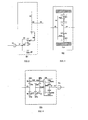
Figure 1 . - Consists of a detailed schematic representation of the three subsystems that comprise the complete transmission and the manner in which these are connected. -
Figure 2 . - Consists of a schematic representation of subsystem S1 corresponding to the driving and amplitude regulation mechanism. -
Figure 3 . - Consists of a schematic representation of subsystem S2 corresponding to the transmission's inertia regulation mechanism. -
Figure 4 . - Consists of a schematic representation of subsystem S3 corresponding to the oscillating movement rectification at the inertia regulation mechanism's output. -
Figure 5 . - Represents the transmission flow of movement in a determined oscillating direction of the output shaft of subsystem S2. -
Figure 6 . - Represents the transmission flow of movement in the direction opposite the oscillation with respect to the previous output shaft of subsystem S2. -
Figure 7 . - Consists of a schematic representation of the driving mechanism for the reference position corresponding to the minimum oscillation amplitude. -
Figure 8 . - Consists of a schematic representation of the driving mechanism for the position corresponding to the maximum oscillation amplitude. - The inertia element of the developed dynamic CVT is comprised of an epicyclic reducer with mass added to the crown. Said epicyclic reducer is inserted upside down into the CVT; therefore, the reducer's input shaft is connected to the satellite holder and the output shaft to the planet. Therefore, in an assembly of this type, the epicyclic reducer would be multiplying the input speed.
- The transmission regulation is based on the aforementioned property of the inertia element and the assembly. When acceleration is applied to the satellite holder while the planet is maintained blocked, the crown's response is to accelerate with a similar type of outcome. Due to the acceleration experienced by the crown and while this acceleration lasts, a torque is generated at the planet. Once the crown acceleration process ceases, the torque at the planet is null.
- As a consequence, by subjecting the satellite holder to a speed law that produces continuous accelerations, a resistant torque can be overcome at the output shaft. For this purpose, an angular speed law is used at the input shaft in the form of an oscillating signal, which is generated by means of a driving mechanism. At the same time, the driving mechanism regulates the amplitude of said angular velocity. The signal at the planet also has an oscillating nature; therefore, a movement rectifying mechanism is required.
- The crown movement carries with it an additional degree of freedom. The adding of mass to the epicyclic train's crown allows said element to become a power regulation inertia mechanism. This regulation consists of cyclic power accumulations and cessions that allow the transmission to adapt to each one of the operating conditions it is subjected to.
- As seen in the
FIG 1 , the complete transmission system includes three subsystems positioned in series. - The purpose of the first subsystem S1 (
FIG. 2 ) is to transform the signal originating from the drive system through shaft E1 (FIGs. 1 and2 ) into an angular oscillating speed signal with a variable amplitude at shaft E2 (FIGs. 1 ,2 and 3 ); this shaft is the input to the second subsystem S2 (FIG. 3 ). Bar B1 (FIGs. 1 and2 ) consists of a handle with a fixed radius R, which transmits the circular movement of its end to control gear EC (FIGs. 1 and2 ). This EC element is engaged with the control crown CC (FIGs. 1 and2 ) and spinning about the inner face of the crown, while said crown is fixed in its position as determined by the driving element EA (FIGs. 1 and2 ). Said EA element uses a worm gear to drive the outer face of control crown CC in order to control its relative position with respect to the reference position, corresponding for example, to the minimum oscillating amplitude (FIG. 7 ). Bar B2 (FIGs. 1 and2 ) is joined at a point P (FIGs. 1 and2 ) to the EC, with said point located at a radius R from the centre of the EC. The union at point P is carried out in such a manner to allow the relative turn between the EC elements and B2. - In the previous arrangement of subsystem S1, the diameter of control gear EC is equal to the radius of the inner face of control crown CC. Under this configuration, the hypocycloid curve generated by point P and therefore, the end of bar B2 at said point, degenerates to a straight line that is described by the inner diameter of control crown CC. Driving shaft EA and modifying the position of crown CC with respect to the reference position, the different possible diameters are described. This way, the oscillation transmitted through bar B2 to counterweight B3 (
FIGs. 1 and2 ) is a function of the described diameter and will vary from an oscillation corresponding to a minimum amplitude at the reference position (FIG. 7 ) to that which generates a maximum amplitude (FIG. 8 ), and which corresponds to an amplitude that is out of phase at a right angle with respect to the reference angle. - The second subsystem S2 (
FIG. 3 ) uses the oscillating signal at the output of the first subsystem S1, acting as a torque regulating element by means of an inertia mechanism consisting of an epicyclic train, to which a mass M is added at crown C (FIGs. 1 and3 ). The satellite holder PS is joined to satellites SA1-SA3 by means of the corresponding shafts ESA1-ESA3 as shown inFIGs. 1 and3 . These satellites are engaged to crown C as well as to planet PL (FIGs. 1 and3 ), in a manner so the oscillating movement is transmitted to both elements. A mass M is uniformly added to crown C, with which said crown acquires the function of the transmission's inertia regulation element. Two predominant power transmission modes exist in subsystem S2, through which power is transmitted from the E1 input shaft to the E4 output shaft (FIG. 1 and4 ). The power is transmitted in a manner that the law of oscillating angular accelerations that is exerted over the crown causes accelerations and decelerations of the crown associated with kinetic energy accumulations and cessions of subsystem S2. In the first of the operating modes, the power supplied to the transmission through shaft E1 is used to accelerate crown C, which accumulates kinetic energy and in providing torque to output shaft E4. In the second mode, the power supplied by input shaft E1 as well as the power released by crown C as it decelerates are used to supply torque to output shaft E4. A brief transition period exists between these two main modes of operation. - The third subsystem S3 (
FIG. 4 ) transforms the oscillating signal coming from subsystem S2 into a single direction of rotation. This subsystem S3 consists of a rectifier mechanism that is based on free wheels or any other type of mechanical diodes. The movement of shaft E3 (FIGs. 1 ,3 and 4 ), output shaft of subsystem S2 and input to subsystem S3, transmits its rotating movement to gear ER2 as well as to ER5 through gear ER1 as shown inFIGs. 1 and4 . - When the oscillating movement transmitted through shaft E3 rotates clockwise, free wheel RL1 (
FIGs. 1 and4 ) located on the outside of gear ER2 is engaged, while free wheel RL3 (FIGs. 1 and4 ), located on the inside of gear ER5 is disengaged. Therefore, in this configuration the movement is transmitted only through gear ER2, which in turn transmits the movement of gear ER3 (FIGs. 1 and4 ) by means of shaft divider ED1 (FIGs. 1 and4 ). The movement of gear ER3 is transmitted to gear ER4 (FIGs. 1 and4 ), which spins attached to the satellite holder of the movement rectifier mechanism PSR (FIGs. 1 and4 ). The direction of rotation of the satellite holder is transmitted to the rectifier mechanism's planet and therefore to output shaft E4 by means of satellites SAR1-SAR3 (FIGs. 1 and4 ). In this configuration where shaft E3 turns clockwise, the crown of the rectifier mechanism CR (FIGs. 1 and4 ) remains blocked; in other words, with a null angular speed. Since the tendency of the crown CR in this configuration, for a clockwise rotation of the satellite holder PSR would be to rotate in the opposite direction, free wheel RL4 (FIGs. 1 and4 ), which is located in gear ER6 (FIGs. 1 and4 ), is included in order to cancel its movement in that direction keeping crown CR blocked. - By the contrary, when the oscillating movement that is transmitted through shaft E3 is counter-clockwise, free wheel RL3 located inside gear ER5 is engaged while free wheel RL1 located inside gear ER2 is disengaged. In this configuration, the movement is transmitted only through gear ER5, which transmits the movement to gear ER6 through divider shaft ED2 (
FIGs. 1 and4 ). The movement of gear ER6 is transmitted to the crown CR, which will rotate counter-clockwise. In this configuration where the crown of the rectifier mechanism CR rotates counter-clockwise, the satellite holder would tend to rotate counter-clockwise and therefore, it would force gear ER4 to rotate in that direction, which rotates attached to the satellite holder PSR. This momentum would cause gear ER3 to turn clockwise. This momentum would be cancelled by the installation of free wheel RL2 (FIGs. 1 and4 ), which would cause the satellite holder PSR to be blocked. In this configuration, all of the crown's movement is transmitted to output shaft E4, which would turn clockwise. - This way, when shaft E3 turns clockwise, the power transmission is carried out as shown in
FIG. 5 , while as shaft E3 turns counter-clockwise, the power transmission is carried out as shown inFIG. 6 . This way, the oscillating movement is transformed into a single direction of rotation, taking advantage of the oscillating movements of shaft E3 in both directions in order to overcome a determined load value at the output shaft of transmission E4. - In subsystem S3, which includes the movement rectifier mechanism described herein, the adequate ratios between gears should be maintained in order for the rotation of the output shaft corresponding to both aforementioned configurations to be of equal magnitude for each of them. With this, the torque transmitted by subsystem S2 at shaft E3 would be symmetrical for a specific load value at the transmission's output shaft E4. This way, the operation of subsystem S2, the inertia regulation mechanism and therefore, of the entire transmission would be as symmetrical and regular as possible.
Claims (24)
- Continuously variable transmission system that is characterized in that it includes at least:- a first drive and regulation subsystem that transforms the rotating movement of a drive element connected to its input shaft into a oscillating angular movement with a variable amplitude at the output shaft of this subsystem;- a second torque inertia regulation subsystem that incorporates at least an additional mass and an input shaft that receives the oscillating movement with a variable amplitude of the first subsystem, obtaining an oscillating angular movement at the output shaft of the second subsystem;- a third movement rectification subsystem that converts the oscillating movement it receives from the second subsystem into a single direction of rotation at the output shaft of the third subsystem.
- Continuously variable transmission system in accordance with claim 1, characterized in that the subsystems are arranged independently.
- Continuously variable transmission system in accordance with claim 1, characterized in that the subsystems are partially grouped with each other.
- Continuously variable transmission system in accordance with claim 1, characterized in that the subsystems are completely grouped with each other
- Continuously variable transmission system in accordance with any of the aforementioned claims, characterized in that the first subsystem incorporates at least one drive mechanism that generates a movement with a variable amplitude, oscillating and centred at zero.
- Continuously variable transmission system in accordance with claims 1 to 4, characterized in that the first subsystem incorporates at least one drive mechanism that generates a movement with a variable amplitude, oscillating and not centred at zero.
- Continuously variable transmission system in accordance with any of the aforementioned claims, characterized in that the torque inertia regulation subsystem includes at least one epicyclic train.
- Continuously variable transmission system in accordance with claims 1 to 6, characterized in that the torque inertia regulation subsystem includes at least one differential mechanism.
- Continuously variable transmission system in accordance with any of the aforementioned claims, characterized in that the added mass is driven directly by any of the torque inertia regulation subsystem's elements.
- Continuously variable transmission system in accordance with claims 1 to 8, characterized in that the added mass is driven indirectly by any of the torque inertia regulation subsystem's elements.
- Continuously variable transmission system in accordance with claims 1 to 6, 9 or 10, characterized in that the torque inertia regulation subsystem incorporates at least one differential mechanism installed in series.
- Continuously variable transmission system in accordance with any of the aforementioned claims, characterized in that the torque inertia regulation subsystem incorporates the combination of at least one differential mechanism installed in parallel.
- Continuously variable transmission system in accordance with any of the aforementioned claims, characterized in that an out of phase drive mechanism is added to the first drive and regulation subsystem.
- Continuously variable transmission system in accordance with any of the aforementioned claims, characterized in that the first subsystem incorporates at least two oscillating signal generating mechanisms for the purpose of improving the balance or for any other purpose.
- Continuously variable transmission system in accordance with any of the aforementioned claims, characterized in that the amplitude of the oscillating output speed of the first subsystem is not regulated, and therefore the entire subsystem acts as a torque converter.
- Continuously variable transmission system in accordance with any of the aforementioned claims, characterized in that the first subsystem incorporates a bar (B2) acting as a rod connected to a rear bar acting as a rocker arm (B3) attached to the output shaft (E2) and also connected at a radial point (P) of the control gear (EC) that is associated with a crown (CC), while this control gear is coupled to a shaft associated with the initial input shaft (WE) by means of a bar (B1).
- Continuously variable transmission system in accordance with the aforementioned claim, characterized in that it incorporates a drive element (EA) like a worm gear, associated with the crown (CC) of the first subsystem (S1) for the purpose of regulating the amplitude of the angular speed of output shaft (E2) of said subsystem.
- Continuously variable transmission system in accordance with claims 1 to 7, characterized in that the epicyclic train of the second inertia regulation subsystem (S2) includes a satellite holder (PS), which is attached to input shaft (E2), satellite gears, (SA1) to (SA3), that engage with the inner face of crown (C) of that epicyclic train, which has a distributed mass (M) and a planet gear (PL), which is attached to output shaft (E3) of the second inertia regulation subsystem (S2).
- Continuously variable transmission system in accordance with any of the aforementioned claims, characterized in that the third rectifying subsystem includes at least the following:- an epicyclic train;- a rectification based on the use of free wheels, other type of mechanical diodes or any other system that allows dividing the power flow into several paths, so the subsequent sum of these flows causes a movement in a single direction of rotation of the output shaft, since it partially or completely as an alternative, restricts the degree of additional freedom of the epicyclic train.
- Continuously variable transmission system in accordance with claims 1 to 18, characterized in that the rectifying subsystem includes at least the following:- a differential mechanism;- a rectification based on the use of free wheels, other type of mechanical diodes or any other system that allows dividing the power flow into several paths, so the subsequent sum of these flows causes a movement in a single direction of rotation at the output shaft, since it partially or completely as an alternative, restricts the degree of additional freedom of the differential mechanism.
- Continuously variable transmission system in accordance with claim 19, characterized in that the movement rectification subsystem (S3) includes an epicyclic train, whose output shaft (E4), which always rotates in a single direction, can receive the movement from input shaft (E3), which is attached to a gear (ER1) by means of a first transmission cycle that changes the direction of rotation of that shaft (E4) and by means of a second transmission cycle that maintains the direction of rotation from input shaft (E3) to output shaft (E4).
- Continuously variable transmission system in accordance with claim 21, characterized in that the transmission cycles of the movement rectification subsystem (S3) include:- two divider shafts (ED1) and (ED2), to which two pairs of rear gears are connected (ER2) and (ER5) that engage with input gear (ER1) and two front gears (ER6) and (ER3), respectively associating free pinions (RL1), (RL3), (RL4), and (RL2), with those two pairs of gears and which may be anchored or not to their respective gears;- a gear (ER4) that engages with one of the rear gears (ER3) while that gear (ER4) is attached to a satellite holder (PSR) that drags satellites (SAR1) to (SAR3), and at the same time are engaged to the crown gear (CR) and to a planet gear (PR) of the epicyclic train, planet (PR) which is connected to output shaft (E4);- a gear connected to the crown (CR) of the epicyclic train and is engaged with rear gear (ER6).
- Continuously variable transmission system, characterized in that it incorporates a rectification subsystem that includes at least the following:- an epicyclic train;- a rectification based on the use of free wheels, other type of mechanical diodes or any other system that allows dividing the power flow into several paths, so the subsequent sum of these flows causes a movement in a single direction of rotation at the output shaft, since it partially or completely as an alternative, restricts the degree of additional freedom of the epicyclic train.
- Continuously variable transmission system, characterized in that it incorporates a rectification subsystem that includes at least the following:- a differential mechanism;- a rectification based on the use of free wheels, other type of mechanical diodes or any other system that allows dividing the power flow into several paths, so the subsequent sum of these flows causes a movement in a single direction of rotation at the output shaft, since it partially or completely as an alternative, restricts the degree of additional freedom of the differential mechanism.
Applications Claiming Priority (2)
| Application Number | Priority Date | Filing Date | Title |
|---|---|---|---|
| ES200803625A ES2369448B1 (en) | 2008-12-19 | 2008-12-19 | CONTINUOUSLY VARIABLE TRANSMISSION SYSTEM. |
| PCT/ES2009/000175 WO2010070158A1 (en) | 2008-12-19 | 2009-06-26 | Continuously variable transmission system |
Publications (3)
| Publication Number | Publication Date |
|---|---|
| EP2360396A1 true EP2360396A1 (en) | 2011-08-24 |
| EP2360396A4 EP2360396A4 (en) | 2012-06-27 |
| EP2360396B1 EP2360396B1 (en) | 2013-08-28 |
Family
ID=42268347
Family Applications (1)
| Application Number | Title | Priority Date | Filing Date |
|---|---|---|---|
| EP09832964.2A Not-in-force EP2360396B1 (en) | 2008-12-19 | 2009-06-26 | Continuously variable transmission system |
Country Status (5)
| Country | Link |
|---|---|
| US (1) | US8784250B2 (en) |
| EP (1) | EP2360396B1 (en) |
| JP (1) | JP2012512998A (en) |
| ES (2) | ES2369448B1 (en) |
| WO (1) | WO2010070158A1 (en) |
Cited By (1)
| Publication number | Priority date | Publication date | Assignee | Title |
|---|---|---|---|---|
| GB2524380A (en) * | 2014-03-21 | 2015-09-23 | Schuler Pressen Gmbh | Drive device with a hypocycloid gear assembly for a forming machine |
Families Citing this family (4)
| Publication number | Priority date | Publication date | Assignee | Title |
|---|---|---|---|---|
| CN103851147A (en) * | 2014-03-18 | 2014-06-11 | 奇瑞重工股份有限公司 | CVT (continuously variable transmission) speed changer based on variable-stroke reciprocating motion |
| DE102021116061A1 (en) | 2021-04-16 | 2022-10-20 | Liebherr-Components Biberach Gmbh | Drive train assembly for driving a work unit with a fluctuating load |
| EP4287818B1 (en) | 2021-04-16 | 2024-10-30 | Liebherr-Components Biberach GmbH | Powertrain for driving a working unit with varying load |
| RO137469A2 (en) * | 2021-11-25 | 2023-05-30 | Ştefan Ciolacu | Device for increasing efficiency of any rotary power generating system with progressive variation |
Family Cites Families (33)
| Publication number | Priority date | Publication date | Assignee | Title |
|---|---|---|---|---|
| GB191221414A (en) | 1912-09-20 | 1913-08-14 | Wilfred Hunt | A Rotary Mechanism for the Transmission of Power at Variable Speeds. |
| GB191319904A (en) | 1913-09-03 | 1914-04-16 | Wilfred Hunt | Improvements in Rotary Mechanisms for the Transmission of Power at Variable Speeds. |
| GB185022A (en) | 1921-08-31 | 1922-08-31 | George Constantinesco | An improved method and means for transmitting power from prime movers such as internal combustion engines to driven shafts, particularly for locomotives or other vehicles driven by internal combustion engines |
| GB363985A (en) * | 1930-07-24 | 1931-12-24 | Sidney Macintyre Lewis Hall | Improvements in or relating to variable speed mechanism and power transmission gear |
| US1860383A (en) * | 1930-08-20 | 1932-05-31 | Henry B Chalmers | Oscillatory and unidirectional torque mechanism |
| GB405610A (en) * | 1932-07-06 | 1934-02-06 | David Werner Berlin | Improvements in variable speed gears |
| FR799682A (en) * | 1935-03-20 | 1936-06-17 | Mode of transformation of a reciprocating rectilinear motion into a circular motion or vice versa | |
| GB531921A (en) * | 1939-07-21 | 1941-01-14 | Walter Charles Pitter | Improvements in or relating to speed changing gear |
| GB610088A (en) * | 1941-07-07 | 1948-10-11 | A Pinguely Ets | Change speed mechanism |
| GB739713A (en) * | 1952-06-18 | 1955-11-02 | Tootal Broadhurst Lee Co Ltd | Improvements in or relating to infinitely variable speed gear mechanisms |
| US3581584A (en) | 1968-01-08 | 1971-06-01 | Nat Res Dev | Torque converter |
| US3955428A (en) * | 1974-11-01 | 1976-05-11 | Ward Carter J | Mechanical automatic torque converter |
| US4336870A (en) | 1977-01-06 | 1982-06-29 | Shea Inventive Designs | Torque exchange coupling |
| DE2921326A1 (en) * | 1978-07-14 | 1980-01-24 | Gino Dr Ing Franch | MECHANICAL SPEED TORQUE CONVERTER |
| US4535730A (en) * | 1980-12-08 | 1985-08-20 | Allen Dillis V | Rocker engine |
| US4796477A (en) * | 1983-12-05 | 1989-01-10 | Brems John Henry | Rotary reversible indexing mechanism |
| GB2215415B (en) * | 1988-03-02 | 1992-04-15 | Peter Goss | Variable speed transmission |
| US5108352A (en) * | 1988-08-15 | 1992-04-28 | Pires Paul B | Modified cranking mechanism for epicyclic transmission |
| US5116292A (en) * | 1991-08-01 | 1992-05-26 | Han Kyung S | Variable drive transmission |
| US5134894A (en) | 1991-09-30 | 1992-08-04 | Tam Isaac Y | Inertial masses mediated rotational energy coupler |
| US5860321A (en) | 1995-03-15 | 1999-01-19 | Williams; Eugene A. | Power transmission utilizing conversion of inertial forces |
| WO1997029301A1 (en) * | 1996-02-06 | 1997-08-14 | Kenji Mimura | Variable speed change gear |
| US5833567A (en) | 1997-03-26 | 1998-11-10 | Fernandez; Angel | Inertial power transmission |
| ES2141019B1 (en) * | 1997-09-19 | 2000-10-16 | Benitez Francisco A Garcia | VARIABLE CONTINUOUS RELATION TRANSMISSION SYSTEM. |
| US6044718A (en) | 1998-06-02 | 2000-04-04 | Lester; William T. | Continuously variable transmission utilizing oscillating torque and one way drives |
| US20010047925A1 (en) * | 1999-05-11 | 2001-12-06 | Triple/S Dynamics, Inc. | Device and method for conveying materials |
| US6068570A (en) * | 1999-06-21 | 2000-05-30 | Han; Kyung Soo | Variable speed transmission system and differential |
| US6537168B1 (en) * | 2000-10-13 | 2003-03-25 | Kyung Soo Han | Variable speed transmission systems and rotary motion controls |
| CA2435728C (en) * | 2001-01-24 | 2008-12-23 | Hasan Basri Ozdamar | Motor with rotary connecting rod bolt |
| ATE524644T1 (en) * | 2005-07-07 | 2011-09-15 | Chuy-Nan Chio | DEVICE FOR GENERATING KINETIC ENERGY |
| DE102008022384B4 (en) * | 2008-05-06 | 2014-02-13 | Bernd Grande | Propeller device and its use in a vehicle drive device or an energy conversion device |
| US8485933B2 (en) * | 2010-07-20 | 2013-07-16 | Differential Dynamics Corporation | Infinitely variable motion control (IVMC) for river turbines |
| US8641570B2 (en) * | 2010-07-20 | 2014-02-04 | Differential Dynamics Corporation | Infinitely variable motion control (IVMC) for generators, transmissions and pumps/compressors |
-
2008
- 2008-12-19 ES ES200803625A patent/ES2369448B1/en active Active
-
2009
- 2009-06-26 US US13/140,005 patent/US8784250B2/en active Active
- 2009-06-26 ES ES09832964.2T patent/ES2437345T3/en active Active
- 2009-06-26 JP JP2011541523A patent/JP2012512998A/en active Pending
- 2009-06-26 EP EP09832964.2A patent/EP2360396B1/en not_active Not-in-force
- 2009-06-26 WO PCT/ES2009/000175 patent/WO2010070158A1/en not_active Ceased
Cited By (1)
| Publication number | Priority date | Publication date | Assignee | Title |
|---|---|---|---|---|
| GB2524380A (en) * | 2014-03-21 | 2015-09-23 | Schuler Pressen Gmbh | Drive device with a hypocycloid gear assembly for a forming machine |
Also Published As
| Publication number | Publication date |
|---|---|
| EP2360396B1 (en) | 2013-08-28 |
| ES2437345T3 (en) | 2014-01-10 |
| WO2010070158A1 (en) | 2010-06-24 |
| JP2012512998A (en) | 2012-06-07 |
| EP2360396A4 (en) | 2012-06-27 |
| ES2369448B1 (en) | 2012-09-18 |
| US20120220414A1 (en) | 2012-08-30 |
| US8784250B2 (en) | 2014-07-22 |
| ES2369448A1 (en) | 2011-12-01 |
Similar Documents
| Publication | Publication Date | Title |
|---|---|---|
| US20120220414A1 (en) | Continuously Variable Transmission System | |
| ES2113270A1 (en) | Torsional vibration damper with a planetary gearset | |
| CN106958641B (en) | Planetary differential gear shaft | |
| EP3431816A1 (en) | Continuously infinite variable transmission system | |
| US4671134A (en) | Automatic transmission for motorcycles | |
| US12504058B2 (en) | Device for increasing the efficiency of any rotary power generating system with progressive variation | |
| US1791386A (en) | Variable-speed gear or torque converter | |
| Morales et al. | A review of dynamic CVT-IVT transmissions | |
| US2476245A (en) | Variable transmission | |
| JP2004316892A (en) | Torque transmitting coupling | |
| RU2174202C2 (en) | Automatic stepless gearing | |
| RU2083385C1 (en) | Mechanical automatic stepless gearbox | |
| US2667794A (en) | Variable speed power transmission mechanism | |
| RU2313019C2 (en) | High-torque non-friction variable-speed drive | |
| US20060240936A1 (en) | Self-regulating continuosly variable transmission | |
| RU2212575C1 (en) | Automatic inertia impulse variable speed drive | |
| SU497439A2 (en) | Automatic inertial pulse planetary speed variator | |
| US5899113A (en) | Variable speed drive having intermediate alternating movements | |
| WO2019122975A1 (en) | A three-speed differential transmission for increasing rpm in geometric progression with common ratio 3, wherein torque is preserved | |
| SU742654A1 (en) | Inertial stepless gearing | |
| RU2171933C2 (en) | Automatic infintely variable meachanicval transmission | |
| RU2036361C1 (en) | Planet gear with automatically changeable gear ratio | |
| Berselli et al. | Kinematic design and bond graph modeling of an inertia-type infinitely variable transmission | |
| RU2174204C2 (en) | Automatic stepless gearing | |
| WO2003102376B1 (en) | Inertial mechanism enabling transformation of an oscillatory motion into a one-way circular motion |
Legal Events
| Date | Code | Title | Description |
|---|---|---|---|
| PUAI | Public reference made under article 153(3) epc to a published international application that has entered the european phase |
Free format text: ORIGINAL CODE: 0009012 |
|
| 17P | Request for examination filed |
Effective date: 20110608 |
|
| AK | Designated contracting states |
Kind code of ref document: A1 Designated state(s): AT BE BG CH CY CZ DE DK EE ES FI FR GB GR HR HU IE IS IT LI LT LU LV MC MK MT NL NO PL PT RO SE SI SK TR |
|
| DAX | Request for extension of the european patent (deleted) | ||
| REG | Reference to a national code |
Ref country code: DE Ref legal event code: R079 Ref document number: 602009018448 Country of ref document: DE Free format text: PREVIOUS MAIN CLASS: F16H0029040000 Ipc: F16H0033080000 |
|
| A4 | Supplementary search report drawn up and despatched |
Effective date: 20120531 |
|
| RIC1 | Information provided on ipc code assigned before grant |
Ipc: F16H 33/08 20060101AFI20120524BHEP |
|
| GRAP | Despatch of communication of intention to grant a patent |
Free format text: ORIGINAL CODE: EPIDOSNIGR1 |
|
| RIN1 | Information on inventor provided before grant (corrected) |
Inventor name: CENTENO BAEZ, GABRIEL Inventor name: GARCIA BENITEZ, FRANCISCO DE ASIS Inventor name: MORALES SANCHEZ, FRANCISCO JOSE Inventor name: PEREZ GUERRERO, FRANCISCO DE BORJA |
|
| GRAS | Grant fee paid |
Free format text: ORIGINAL CODE: EPIDOSNIGR3 |
|
| GRAA | (expected) grant |
Free format text: ORIGINAL CODE: 0009210 |
|
| AK | Designated contracting states |
Kind code of ref document: B1 Designated state(s): AT BE BG CH CY CZ DE DK EE ES FI FR GB GR HR HU IE IS IT LI LT LU LV MC MK MT NL NO PL PT RO SE SI SK TR |
|
| REG | Reference to a national code |
Ref country code: GB Ref legal event code: FG4D |
|
| REG | Reference to a national code |
Ref country code: CH Ref legal event code: EP |
|
| REG | Reference to a national code |
Ref country code: AT Ref legal event code: REF Ref document number: 629543 Country of ref document: AT Kind code of ref document: T Effective date: 20130915 |
|
| REG | Reference to a national code |
Ref country code: IE Ref legal event code: FG4D |
|
| REG | Reference to a national code |
Ref country code: DE Ref legal event code: R096 Ref document number: 602009018448 Country of ref document: DE Effective date: 20131024 |
|
| REG | Reference to a national code |
Ref country code: ES Ref legal event code: FG2A Ref document number: 2437345 Country of ref document: ES Kind code of ref document: T3 Effective date: 20140110 |
|
| REG | Reference to a national code |
Ref country code: AT Ref legal event code: MK05 Ref document number: 629543 Country of ref document: AT Kind code of ref document: T Effective date: 20130828 |
|
| REG | Reference to a national code |
Ref country code: LT Ref legal event code: MG4D |
|
| REG | Reference to a national code |
Ref country code: NL Ref legal event code: VDEP Effective date: 20130828 |
|
| PG25 | Lapsed in a contracting state [announced via postgrant information from national office to epo] |
Ref country code: PT Free format text: LAPSE BECAUSE OF FAILURE TO SUBMIT A TRANSLATION OF THE DESCRIPTION OR TO PAY THE FEE WITHIN THE PRESCRIBED TIME-LIMIT Effective date: 20131230 Ref country code: SE Free format text: LAPSE BECAUSE OF FAILURE TO SUBMIT A TRANSLATION OF THE DESCRIPTION OR TO PAY THE FEE WITHIN THE PRESCRIBED TIME-LIMIT Effective date: 20130828 Ref country code: AT Free format text: LAPSE BECAUSE OF FAILURE TO SUBMIT A TRANSLATION OF THE DESCRIPTION OR TO PAY THE FEE WITHIN THE PRESCRIBED TIME-LIMIT Effective date: 20130828 Ref country code: NO Free format text: LAPSE BECAUSE OF FAILURE TO SUBMIT A TRANSLATION OF THE DESCRIPTION OR TO PAY THE FEE WITHIN THE PRESCRIBED TIME-LIMIT Effective date: 20131128 Ref country code: IS Free format text: LAPSE BECAUSE OF FAILURE TO SUBMIT A TRANSLATION OF THE DESCRIPTION OR TO PAY THE FEE WITHIN THE PRESCRIBED TIME-LIMIT Effective date: 20131228 Ref country code: CY Free format text: LAPSE BECAUSE OF FAILURE TO SUBMIT A TRANSLATION OF THE DESCRIPTION OR TO PAY THE FEE WITHIN THE PRESCRIBED TIME-LIMIT Effective date: 20130626 Ref country code: HR Free format text: LAPSE BECAUSE OF FAILURE TO SUBMIT A TRANSLATION OF THE DESCRIPTION OR TO PAY THE FEE WITHIN THE PRESCRIBED TIME-LIMIT Effective date: 20130828 Ref country code: LT Free format text: LAPSE BECAUSE OF FAILURE TO SUBMIT A TRANSLATION OF THE DESCRIPTION OR TO PAY THE FEE WITHIN THE PRESCRIBED TIME-LIMIT Effective date: 20130828 |
|
| REG | Reference to a national code |
Ref country code: NL Ref legal event code: VDEP Effective date: 20130828 |
|
| PG25 | Lapsed in a contracting state [announced via postgrant information from national office to epo] |
Ref country code: LV Free format text: LAPSE BECAUSE OF FAILURE TO SUBMIT A TRANSLATION OF THE DESCRIPTION OR TO PAY THE FEE WITHIN THE PRESCRIBED TIME-LIMIT Effective date: 20130828 Ref country code: BE Free format text: LAPSE BECAUSE OF FAILURE TO SUBMIT A TRANSLATION OF THE DESCRIPTION OR TO PAY THE FEE WITHIN THE PRESCRIBED TIME-LIMIT Effective date: 20130828 Ref country code: PL Free format text: LAPSE BECAUSE OF FAILURE TO SUBMIT A TRANSLATION OF THE DESCRIPTION OR TO PAY THE FEE WITHIN THE PRESCRIBED TIME-LIMIT Effective date: 20130828 Ref country code: GR Free format text: LAPSE BECAUSE OF FAILURE TO SUBMIT A TRANSLATION OF THE DESCRIPTION OR TO PAY THE FEE WITHIN THE PRESCRIBED TIME-LIMIT Effective date: 20131129 Ref country code: FI Free format text: LAPSE BECAUSE OF FAILURE TO SUBMIT A TRANSLATION OF THE DESCRIPTION OR TO PAY THE FEE WITHIN THE PRESCRIBED TIME-LIMIT Effective date: 20130828 Ref country code: SI Free format text: LAPSE BECAUSE OF FAILURE TO SUBMIT A TRANSLATION OF THE DESCRIPTION OR TO PAY THE FEE WITHIN THE PRESCRIBED TIME-LIMIT Effective date: 20130828 |
|
| PG25 | Lapsed in a contracting state [announced via postgrant information from national office to epo] |
Ref country code: CY Free format text: LAPSE BECAUSE OF FAILURE TO SUBMIT A TRANSLATION OF THE DESCRIPTION OR TO PAY THE FEE WITHIN THE PRESCRIBED TIME-LIMIT Effective date: 20130828 |
|
| PG25 | Lapsed in a contracting state [announced via postgrant information from national office to epo] |
Ref country code: NL Free format text: LAPSE BECAUSE OF FAILURE TO SUBMIT A TRANSLATION OF THE DESCRIPTION OR TO PAY THE FEE WITHIN THE PRESCRIBED TIME-LIMIT Effective date: 20130828 Ref country code: DK Free format text: LAPSE BECAUSE OF FAILURE TO SUBMIT A TRANSLATION OF THE DESCRIPTION OR TO PAY THE FEE WITHIN THE PRESCRIBED TIME-LIMIT Effective date: 20130828 Ref country code: EE Free format text: LAPSE BECAUSE OF FAILURE TO SUBMIT A TRANSLATION OF THE DESCRIPTION OR TO PAY THE FEE WITHIN THE PRESCRIBED TIME-LIMIT Effective date: 20130828 Ref country code: RO Free format text: LAPSE BECAUSE OF FAILURE TO SUBMIT A TRANSLATION OF THE DESCRIPTION OR TO PAY THE FEE WITHIN THE PRESCRIBED TIME-LIMIT Effective date: 20130828 Ref country code: SK Free format text: LAPSE BECAUSE OF FAILURE TO SUBMIT A TRANSLATION OF THE DESCRIPTION OR TO PAY THE FEE WITHIN THE PRESCRIBED TIME-LIMIT Effective date: 20130828 Ref country code: CZ Free format text: LAPSE BECAUSE OF FAILURE TO SUBMIT A TRANSLATION OF THE DESCRIPTION OR TO PAY THE FEE WITHIN THE PRESCRIBED TIME-LIMIT Effective date: 20130828 |
|
| REG | Reference to a national code |
Ref country code: DE Ref legal event code: R097 Ref document number: 602009018448 Country of ref document: DE |
|
| PLBE | No opposition filed within time limit |
Free format text: ORIGINAL CODE: 0009261 |
|
| STAA | Information on the status of an ep patent application or granted ep patent |
Free format text: STATUS: NO OPPOSITION FILED WITHIN TIME LIMIT |
|
| 26N | No opposition filed |
Effective date: 20140530 |
|
| REG | Reference to a national code |
Ref country code: DE Ref legal event code: R097 Ref document number: 602009018448 Country of ref document: DE Effective date: 20140530 |
|
| PG25 | Lapsed in a contracting state [announced via postgrant information from national office to epo] |
Ref country code: MC Free format text: LAPSE BECAUSE OF FAILURE TO SUBMIT A TRANSLATION OF THE DESCRIPTION OR TO PAY THE FEE WITHIN THE PRESCRIBED TIME-LIMIT Effective date: 20130828 Ref country code: LU Free format text: LAPSE BECAUSE OF FAILURE TO SUBMIT A TRANSLATION OF THE DESCRIPTION OR TO PAY THE FEE WITHIN THE PRESCRIBED TIME-LIMIT Effective date: 20140626 |
|
| REG | Reference to a national code |
Ref country code: CH Ref legal event code: PL |
|
| REG | Reference to a national code |
Ref country code: IE Ref legal event code: MM4A |
|
| PG25 | Lapsed in a contracting state [announced via postgrant information from national office to epo] |
Ref country code: LI Free format text: LAPSE BECAUSE OF NON-PAYMENT OF DUE FEES Effective date: 20140630 Ref country code: IE Free format text: LAPSE BECAUSE OF NON-PAYMENT OF DUE FEES Effective date: 20140626 Ref country code: CH Free format text: LAPSE BECAUSE OF NON-PAYMENT OF DUE FEES Effective date: 20140630 |
|
| PG25 | Lapsed in a contracting state [announced via postgrant information from national office to epo] |
Ref country code: MT Free format text: LAPSE BECAUSE OF FAILURE TO SUBMIT A TRANSLATION OF THE DESCRIPTION OR TO PAY THE FEE WITHIN THE PRESCRIBED TIME-LIMIT Effective date: 20130828 |
|
| REG | Reference to a national code |
Ref country code: FR Ref legal event code: PLFP Year of fee payment: 8 |
|
| PG25 | Lapsed in a contracting state [announced via postgrant information from national office to epo] |
Ref country code: BG Free format text: LAPSE BECAUSE OF FAILURE TO SUBMIT A TRANSLATION OF THE DESCRIPTION OR TO PAY THE FEE WITHIN THE PRESCRIBED TIME-LIMIT Effective date: 20130828 |
|
| PG25 | Lapsed in a contracting state [announced via postgrant information from national office to epo] |
Ref country code: HU Free format text: LAPSE BECAUSE OF FAILURE TO SUBMIT A TRANSLATION OF THE DESCRIPTION OR TO PAY THE FEE WITHIN THE PRESCRIBED TIME-LIMIT; INVALID AB INITIO Effective date: 20090626 Ref country code: TR Free format text: LAPSE BECAUSE OF FAILURE TO SUBMIT A TRANSLATION OF THE DESCRIPTION OR TO PAY THE FEE WITHIN THE PRESCRIBED TIME-LIMIT Effective date: 20130828 |
|
| REG | Reference to a national code |
Ref country code: FR Ref legal event code: PLFP Year of fee payment: 9 |
|
| PG25 | Lapsed in a contracting state [announced via postgrant information from national office to epo] |
Ref country code: ES Free format text: LAPSE BECAUSE OF NON-PAYMENT OF DUE FEES Effective date: 20140627 |
|
| REG | Reference to a national code |
Ref country code: FR Ref legal event code: PLFP Year of fee payment: 10 |
|
| PG25 | Lapsed in a contracting state [announced via postgrant information from national office to epo] |
Ref country code: MK Free format text: LAPSE BECAUSE OF FAILURE TO SUBMIT A TRANSLATION OF THE DESCRIPTION OR TO PAY THE FEE WITHIN THE PRESCRIBED TIME-LIMIT Effective date: 20130828 |
|
| PGFP | Annual fee paid to national office [announced via postgrant information from national office to epo] |
Ref country code: IT Payment date: 20220621 Year of fee payment: 14 Ref country code: GB Payment date: 20220617 Year of fee payment: 14 |
|
| PGFP | Annual fee paid to national office [announced via postgrant information from national office to epo] |
Ref country code: FR Payment date: 20220628 Year of fee payment: 14 |
|
| PGFP | Annual fee paid to national office [announced via postgrant information from national office to epo] |
Ref country code: DE Payment date: 20220630 Year of fee payment: 14 |
|
| REG | Reference to a national code |
Ref country code: DE Ref legal event code: R119 Ref document number: 602009018448 Country of ref document: DE |
|
| GBPC | Gb: european patent ceased through non-payment of renewal fee |
Effective date: 20230626 |
|
| PG25 | Lapsed in a contracting state [announced via postgrant information from national office to epo] |
Ref country code: DE Free format text: LAPSE BECAUSE OF NON-PAYMENT OF DUE FEES Effective date: 20240103 Ref country code: GB Free format text: LAPSE BECAUSE OF NON-PAYMENT OF DUE FEES Effective date: 20230626 |
|
| PG25 | Lapsed in a contracting state [announced via postgrant information from national office to epo] |
Ref country code: FR Free format text: LAPSE BECAUSE OF NON-PAYMENT OF DUE FEES Effective date: 20230630 |
|
| PG25 | Lapsed in a contracting state [announced via postgrant information from national office to epo] |
Ref country code: IT Free format text: LAPSE BECAUSE OF NON-PAYMENT OF DUE FEES Effective date: 20230626 |
|
| PGFP | Annual fee paid to national office [announced via postgrant information from national office to epo] |
Ref country code: ES Payment date: 20250630 Year of fee payment: 17 |