EP2360369A2 - Ventilvorrichtung für eine Verbrennungskraftmaschine - Google Patents
Ventilvorrichtung für eine Verbrennungskraftmaschine Download PDFInfo
- Publication number
- EP2360369A2 EP2360369A2 EP11150951A EP11150951A EP2360369A2 EP 2360369 A2 EP2360369 A2 EP 2360369A2 EP 11150951 A EP11150951 A EP 11150951A EP 11150951 A EP11150951 A EP 11150951A EP 2360369 A2 EP2360369 A2 EP 2360369A2
- Authority
- EP
- European Patent Office
- Prior art keywords
- valve
- gear
- spring
- combustion engine
- rotary shaft
- Prior art date
- Legal status (The legal status is an assumption and is not a legal conclusion. Google has not performed a legal analysis and makes no representation as to the accuracy of the status listed.)
- Granted
Links
- 238000002485 combustion reaction Methods 0.000 title claims description 10
- 230000005540 biological transmission Effects 0.000 claims abstract description 22
- 230000033001 locomotion Effects 0.000 claims abstract description 15
- 238000011144 upstream manufacturing Methods 0.000 claims description 15
- 230000001105 regulatory effect Effects 0.000 abstract description 2
- 230000008878 coupling Effects 0.000 description 4
- 238000010168 coupling process Methods 0.000 description 4
- 238000005859 coupling reaction Methods 0.000 description 4
- 238000004519 manufacturing process Methods 0.000 description 3
- 230000008859 change Effects 0.000 description 2
- 238000006243 chemical reaction Methods 0.000 description 1
- 238000010276 construction Methods 0.000 description 1
- 239000003344 environmental pollutant Substances 0.000 description 1
- 238000003780 insertion Methods 0.000 description 1
- 230000037431 insertion Effects 0.000 description 1
- 238000012986 modification Methods 0.000 description 1
- 230000004048 modification Effects 0.000 description 1
- 231100000719 pollutant Toxicity 0.000 description 1
- 230000009467 reduction Effects 0.000 description 1
- 230000007704 transition Effects 0.000 description 1
Images
Classifications
-
- F—MECHANICAL ENGINEERING; LIGHTING; HEATING; WEAPONS; BLASTING
- F02—COMBUSTION ENGINES; HOT-GAS OR COMBUSTION-PRODUCT ENGINE PLANTS
- F02M—SUPPLYING COMBUSTION ENGINES IN GENERAL WITH COMBUSTIBLE MIXTURES OR CONSTITUENTS THEREOF
- F02M26/00—Engine-pertinent apparatus for adding exhaust gases to combustion-air, main fuel or fuel-air mixture, e.g. by exhaust gas recirculation [EGR] systems
- F02M26/65—Constructional details of EGR valves
- F02M26/66—Lift valves, e.g. poppet valves
- F02M26/67—Pintles; Spindles; Springs; Bearings; Sealings; Connections to actuators
-
- F—MECHANICAL ENGINEERING; LIGHTING; HEATING; WEAPONS; BLASTING
- F02—COMBUSTION ENGINES; HOT-GAS OR COMBUSTION-PRODUCT ENGINE PLANTS
- F02M—SUPPLYING COMBUSTION ENGINES IN GENERAL WITH COMBUSTIBLE MIXTURES OR CONSTITUENTS THEREOF
- F02M26/00—Engine-pertinent apparatus for adding exhaust gases to combustion-air, main fuel or fuel-air mixture, e.g. by exhaust gas recirculation [EGR] systems
- F02M26/52—Systems for actuating EGR valves
- F02M26/53—Systems for actuating EGR valves using electric actuators, e.g. solenoids
- F02M26/54—Rotary actuators, e.g. step motors
Definitions
- the invention relates to a valve device for an internal combustion engine with a housing, an actuator which generates a torque, a transmission unit, a translationally movable valve, via which a flow cross-section is controlled releasable or closable, a transmission output member which is so coupled to the valve, that the rotational movement of the transmission output member generates a translatory movement of the valve and a spring element, which serves as a return spring.
- valve devices are used for example as exhaust gas recirculation valves.
- a gear unit is rotated, which has a coupling element, via which the rotational movement of the gears is converted into a translational movement of the valve stem.
- an exhaust gas flow which is attributed from the exhaust manifold to the intake manifold for the reduction of pollutant emissions, regulated over a wide range.
- a provision of the valve is in the maroossene position to continue to ensure the safe operation of the engine,
- an exhaust gas recirculation valve in which a gear unit it is designed in the form of an eccentric coupling element with a backdrop, in the backdrop runs a ball bearing, which in turn connected to a valve stem of a Veritiis.
- a spring On the axis of rotation of the coupling element, a spring is arranged, the be ⁇ the Koppiungselement so be! That the valve is rotated in a closing position: is.
- a second spring is arranged around the Ventiistange and this constantly charged against the upper track of the scenery, a multi-stage transmission is not disclosed.
- the spring element is arranged such that on the one hand a gear or a rotary shaft of the gear unit and on the other hand, the valve are loaded in the closing direction of the valve. Accordingly, only a single component is needed for both functions, so both the backlash of the transmission and the fail-safe function of the valve, which is also easy to install.
- the spring element is a helical spring, which has two spring legs, of which the first spring leg biased acts on the valve and the second spring leg biased to a rotary shaft on which an upstream gear is arranged rotationally fixed or engages the upstream gear, wherein the helical portion of the coil spring surrounds the rotary shaft.
- a helical spring which has two spring legs, of which the first spring leg biased acts on the valve and the second spring leg biased to a rotary shaft on which an upstream gear is arranged rotationally fixed or engages the upstream gear, wherein the helical portion of the coil spring surrounds the rotary shaft.
- the second spring leg is arranged in a slot of the rotary shaft. This achieves an easily assembled arrangement of the spring.
- the transmission output member comprises a gear segment and an opposite relative to a rotation axis actuating portion which engages the valve rod or a fixedly connected to the valve rod portion and is rotatable with the gear segment about the axis of rotation of the gear segment, wherein the rotational movement of the actuating portion of the translational Movement of the valve causes,
- the conversion of the rotational movement of the drive in a transfatory movement of the valve is simplified by such a structure. At the same time there is access to the mounting space for the spring.
- the gear segment on an internal toothing, which meshes with the upstream gear is biased on the rotary shaft or on which the second spring leg. This means that the upstream gear is disposed between the valve rod and the toothed portion of the lever-acting gear segment.
- Such a valve is very compact.
- the gear segment has an outer toothing, which meshes with an upstream gear, is biased on the rotary shaft or on which the second spring leg. This means that the complete acting as a lever sector gear between the upstream gear and the Valve rod is arranged. When the valve moves from standstill in the closing direction, there is no system change of the gearbox.
- the gear unit is a spur gear, this has a small size and is easy to install.
- the return spring can be mounted without much effort in such a transmission and optionally replaced.
- the spur gear on a drive gear which meshes with the larger gear of a double gear, which is rotatably mounted on the rotary shaft and whose smaller gear meshes with the transmission output member and serves as upstream gear.
- a high gear ratio is achieved with the spur gear.
- valve device which ensures the simplest way the functions of a reliable return of the valve and a distortion of the transmission to avoid gearing. This increases the life of the gearbox and ensures the return of the valve in two different ways.
- the entire valve device is simple and inexpensive to manufacture and assemble.
- valve device shown in the figures consists of a only partially in FIG. 3 shown, usually multi-part housing 2, in which an actuator 4 in the form of an electric motor and a snotreibbare via the electric motor gear unit 6 in the form of a spur gear and a translationally movable via the gear unit 6 valve 8 are arranged
- a drive gear 10 is arranged rotationally fixed. This meshes with a larger gear 12 of a double gear 14, which is rotationally fixed: is mounted on a rotary shaft 16 which is mounted in the housing 2 via a bearing 18 A smaller gear 20 of the double gear 14 meshes with an external toothing 22 of a gear segment 24 of a transmission output member 26 and thus serves as an upstream gear to the transmission output member 26 of the transmission unit 6.
- This transmission output member 26 is mounted on a housing 2 fixed to the axis 28, which serves as a rotation axis for the transmission output member 26.
- an actuating portion 30 is formed on the opposite side to the gear segment 24 of the axis of rotation of the transmission output member 26, an actuating portion 30 is formed.
- the actuating portion 30 may, as in the present illustration, be a lever head which engages in a recess 32 which is formed in a valve rod 34 of the valve 8. Instead of this recess, it is also possible to engage the actuating section 30 at other areas fixedly connected to the valve 8. This may be, for example, additional axes fastened to the valve rod 34 or the actuating section 30 lies in a simplest embodiment on the end of the valve rod 34.
- the valve 8 is; a known translationally guided lifting valve with the valve rod 34 and a valve stem 34 fixedly connected Ventilschtmanglied 36 which cooperates with a valve seat 38 which surrounds a flow area 40.
- a further opening 41 is formed, engages by the present invention, a first spring leg 42 serving as a return spring Federelermentes 44 in the form of a helical spring.
- a helical portion 46 of the spring element 44 is wound around the rotary shaft 16, while a second spring leg 48 is disposed in a slot 50 of the rotary shaft 16.
- the first spring leg 42 would be equal to two large, but in the opposite direction running kinks 52, as in FIG. 3 can be seen.
- the spring element 44 is mounted in such a way that a force is exerted on the valve 8 in the closing direction already in the position of the valve 8 closing the flow cross-section 40. Accordingly, the spring element 44 is to be twisted during insertion such that the first leg 42 presses from below against an upper wall of the opening 41 and the second leg 48 via the slot 50 a torque on the rotary shaft 16 exerts, which runs in the present embodiment in the clockwise direction and thus also biases the valve 8 in the closing direction. At the same time, however, this also the teeth of the smaller gear 20 is pressed against the flanks of the teeth of the external teeth 22 of the gear segment 24. As a result, the usual gear play is minimized, since no Zahnfiankencic arises when stopping from the movement, In FIG.
- the spring element also loads the valve rod 34 upward, so that the Veritilschuiteglied 26 is loaded by both spring parts in the direction of the valve seat 38. Equally acting forces arise in any position of the valve 8 when not actuated actuator. Thus, the valve 8 is always loaded by the spring element 44 in the direction of its valve seat.
- FIG. 2 the effective torques when opening the valve 8 are located.
- the torque of the actuator 4 acts in a clockwise direction, so that acts on the double gear 14, a torque in the opposite direction.
- the torque of the gear segment now acts in a clockwise direction, so that the valve 8 is moved via the actuating portion 30 downwardly in the opening direction, an opposite but smaller force acts in the opposite direction by the leg 42 of the spring element 44.
- An opposite torque, which with opening of Valve 8 increases by further rotation of the spring 44 also acts on the valve 8. Accordingly, a change in the tooth flanks arises in each case in the transition from the energized to the de-energized state of the actuator 4. At each standstill of the actuator creates a defined position of the gears to each other by the torque generated by the spring element 44.
- the illustrated valve is easy to assemble and provides: a spring return, both valve stem return and gear minimization, increasing life.
- the resulting assembly and manufacturing costs are very low, and such a valve is particularly suitable as an exhaust gas recirculation valve.
- gear segment can be performed as a full gear, ring gear or internal gear segment.
- various embodiments of the housing are known.
- the arrangement of the second spring leg can also be done on the gear itself as the first spring leg can engage under an element connected to the valve rod.
- Other possible changes are also known to the person skilled in the art.
Landscapes
- Engineering & Computer Science (AREA)
- Chemical & Material Sciences (AREA)
- Combustion & Propulsion (AREA)
- Mechanical Engineering (AREA)
- General Engineering & Computer Science (AREA)
- Mechanically-Actuated Valves (AREA)
- Valve-Gear Or Valve Arrangements (AREA)
Abstract
Description
- Die Erfindung betrifft eine Ventilvorrichtung für eine Verbrennungskraftmaschine mit einem Gehäuse, einem Aktuator, der ein Drehmoment erzeugt, einer Getriebeeinheit, einem translatorisch bewegbaren Ventil, über welches ein Durchströmungsquerschnitt geregelt freigebbar oder verschließbar ist, einem Getriebeabtriebsglied, welches derart mit dem Ventil gekoppelt ist, dass die Drehbewegung des Getriebeabtriebsgliedes eine translatorische Bewegung des Ventils erzeugt und einem Federelement, weiches als Rücksteilfeder dient.
- Derartige Ventilvorrichtungen werden beispielsweise als Abgasrückführventile verwendet. Über die zumeist elektromotorische Antriebseinheit wird eine Getriebeeinheit in Drehung versetzt, die ein Kopplungselement aufweist, über welches die rotatorische Bewegung der Zahnräder in eine translatorische Bewegung der Ventilstange umgewandelt wird. Mittels dieser Ventile wird ein Abgasstrom, der vom Abgaskrümmer zum Saugrohr zur Verminderung von Schadstoffemissionen zurückgeführt wird, über einen weiten Bereich geregelt. Bei diesen elektromotorisch angetriebenen Ventilen muss jedoch gemäß Kundenvorgaben sichergestellt werden, dass bei Ausfall des Elektromotors oder Bruch eines Getrieberades eine Rückstellung des Ventils in die geschiossene Stellung erfolgt, um die sichere Funktion des Verbrennungsmotors weiter sicherstellen zu können,
- So ist aus der
EP 1 632 674 A2 ein Abgasrückführventil bekannt, bei dem eine Getriebeeinheit ihn Form eines exzentrischen Kopplungselementes mit einer Kulisse ausgebildet ist, In der Kulisse läuft ein Kugellager, welches wiederum mit einer Ventilstange eines Veritiis verbunden ist. An der Drehachse des Kopplungselementes ist eine Feder angeordnet, die das Koppiungselement derart be!astet, dass das Ventil in eine verschließende Stellung gedreht: wird. Eine zweite Feder ist um die Ventiistange angeordnet und belastet diese ständig gegen die obere Bahn der Kulisse, Ein mehrstufiges Getriebe wird nicht offenbart. Somit werden eine Spielfreiheit zwischen Ventilstange und Kopplungselement und eine Rückstellung des Ventils bei Ausfall des Aktuators mittels zweier Federelenien-te sichergestellt. Die Anzahl der Bauteile ist relativ hoch, so dass Herstell- und Montagekosten steigen. Des Weiteren sind die Stellkräfte der beiden Federn aufeinander und mit dem Aktuator abzustimmen. - Es ist daher Aufgabe der Erfindung, eine Ventilvorrichtung zu schaffen, mit der eine Spielfreiheit eines vorgeschalteten Getriebes und eine fail-safe Funktion des Ventils auf einfache Weise sichergestellt werden, wobei die Teileanzafil und der .Montageaufwand im Vergleich zu bekannten Ausführungen minimiert werden sollen.
- Diese Aufgabe wird durch den kennzeichnenden Teil des Hauptanspruchs gelöst.
- Demnach ist das Federelement derart angeordnet, dass einerseits ein Zahnrad oder eine Drehwelle der Getriebeeinheit und andererseits das Ventil in Schließrichtung des Ventils belastet sind. Entsprechend wird für beide Funktionen, also sowohl die Spielfreiheit des Getriebes als auch die fail-safe Funktion des Ventils, lediglich ein einzelnes Bauteil benötigt, welches zusätzlich leicht zu montieren ist.
- Vorzugsweise ist das Federelement eine Schraubenfeder, welche zwei Federschenkel aufweist, wovon der erste Federschenkel vorgespannt am Ventil angreift und der zweite Federschenkel vorgespannt an eine Drehwelle, auf der ein vorgeschaltetes Zahnrad drehfest angeordnet ist oder an das vorgeschaltete Zahnrad greift, wobei der schraubenförmige Bereich der Schraubenfeder die Drehwelle umgibt. Ein derartiger Aufbau erleichtert die Montage und gibt eine einfache Möglichkeit zur Realisierung der beiden Federfunktionen.
- In einer weiterführenden Ausführung der Erfindung ist der zweite Federschenkel in einem Schlitz der Drehwelle angeordnet. So wird eine einfach montierbare Anordnung der Feder erreicht.
- In einer bevorzugten Ausführungsform weist das Getriebeabtriebsglied ein Zahnradsegment und einen bezüglich einer Drehachse gegenüberliegenden Betätigungsabschnitt auf, welcher an die Ventilstange oder einen fest mit der Ventilstange verbundenen Bereich greift und mit dem Zahnradsegment um die Drehachse des Zahnradsegmentes drehbar ist, wobei die Drehbewegung des Betätigungsabschnitts die translatorische Bewegung des Ventils verursacht, Die Umwandlung der Drehbewegung des Antriebs in eine transfatorische Bewegung des Ventils wird durch einen derartigen Aufbau vereinfacht. Gleichzeitig ist ein Zugriff zum Montageraum für die Feder vorhanden.
- In einer weiterführenden Ausführung weist das Zahnradsegment eine Innenverzahnung auf, die mit dem vorgeschalteten Zahnrad kämmt, an dessen Drehwelle oder an dem der zweite Federschenkel vorgespannt ist. Die bedeutet, dass das vorgeschaltete Zahnrad zwischen der ventilstange und dem verzahnten Bereich des als Hebel wirkenden Zahnradsegments angeordnet ist. Ein solches Ventil ist sehr kompakt.
- In einer hierzu alternativen Ausführungsform weist das Zahnradsegment eine Außenverzahnung auf, die mit einem vorgeschalteten Zahnrad kämmt, an dessen Drehwelle oder an dem der zweite Federschenkel vorgespannt ist. Dies bedeutet, dass das komplette als Hebel wirkende Zahnsegment zwischen dem vorgeschalteten Zahnrad und der Ventilstange angeordnet ist. Bei Bewegung des Ventils aus dem Stillstand in Schließrichtung entsteht kein Anlagewechsel des Getriebes.
- Vorzugsweise ist die Getriebeeinheit ein Stirnradgetriebe, Dieses weist eine geringe Baugröße auf und ist einfach zu montieren. Insbesondere kann auch die Rückstellfeder ohne größeren Aufwand bei einem derartigen Getriebe montiert und gegebenenfalls ausgetauscht werden.
- Vorteilhafterweise weist das Stirnradgetriebe ein Antriebszahnrad auf, welches mit dem größeren Zahnrad eines Doppelzahnrades kämmt, welches auf der Drehwelle drehfest angeordnet ist und dessen kleineres Zahnrad mit dem Getriebeabtriebsglied kämmt und als vorgeschaltetes Zahnrad dient. In dieser Bauform wird mit dem Stirnradgetriebe eine hohe Übersetzung erreicht.
- Es wird somit eine Ventilvorrichtung geschaffen, welche auf einfachste Weise die Funktionen einer zuverlässigen Rückstellung des Ventils und ein Verspannen des Getriebes zur Vermeidung von Getriebespiel sicherstellt. Dies erhöht die Lebensdauer des Getriebes und stellt auf zwei verschiedene Arten die Rückstellung des Ventils sicher. Zusätzlich ist die gesamte Ventilvorrichtung einfach und kostengünstig herstell- und montierbar.
- Ein Ausführungsbeispiel einer erfindungsgemäßen Ventilvorrichtung ist in den Figuren dargestellt und wird nachfolgend beschrieben,
-
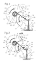
Figur 1 zeigt in schematischer Darstellung eine erfindungsgemäße Ventilvorrichtung mit ihren wesentlichen Bauteilen in Seitenansicht im geschlossenen Zustand. -
Figur 2 zeigt in schematischer Darstellung die erfindungsgernläße Ventilvorrichtung derFigur 1 in Seitenansicht im geschlossenen Zustand. -
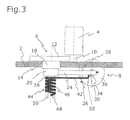
Figur 3 zeigt in schematischer Darstellung die Ventilvorrichtung derFigur 1 in Kopfansicht. - Die in den Figuren dargestellte Ventilvorrichtung besteht: aus einem nur ausschnittsweise in
Figur 3 dargestellten, üblicherweise mehrteiligen Gehäuse 2, in dem ein Aktuator 4 in Form eines Elektromotors sowie eine über den Elektromotor sntreibbare Getriebeeinheit 6 in Form eines Stirnradgetriebes und ein über die Getriebeeinheit 6 translatorisch bewegbares Ventil 8 angeordnet sind, - Auf einer Antriebswelle des Aktuators 4 ist ein Antriebszahnrad 10 drehfest angeordnet. Dieses kämmt mit einem größeren Zahnrad 12 eines Doppelzahnrades 14, welches drehfest: auf einer Drehwelle 16 angeordnet ist, die über ein Lager 18 im Gehäuse 2 gelagert ist Ein kleineres Zahnrad 20 des Doppelzahnrades 14 kämmt mit einer Außenverzahnung 22 eines Zahnradsegmentes 24 eines Getriebeabtriebsgliedes 26 und dient somit als vorgeschaltetes Zahnrad zum Getriebeabtriebsglied 26 der Getriebeeinheit 6. Dieses Getriebeabtriebsglied 26 ist auf einer am Gehäuse 2 befestigten Achse 28 gelagert, die als Drehachse für das Getriebeabtriebsglied 26 dient. An der zum Zahnradsegment 24 gegenüberliegenden Seite der Drehachse des Getriebeabtriebsgliedes 26 ist ein Betätigungsabschnitt 30 ausgebildet.
- Der Betätigungsabschnitt 30 kann, wie In vorliegender Darstellung ein Hebelkopf sein, der in eine Ausnehmung 32 greift, welche in einer Ventilstange 34 des Ventils 8 ausgebildet ist. Anstelle dieser Ausnehmung ist auch ein Eingreifen des Betätigungsabschnittes 30 an anderen fest mit dem Ventil 8 verbundenen Bereichen möglich, Dies können beispielsweise zusätzliche, an der Ventilstange 34 befestigte Achsen sein oder der Betätigungsabschnitt 30 liegt in einer einfachsten Ausführung auf dem Ende der Ventilstange 34 auf.
- Das Ventil 8 ist; ein bekanntes translatorisch geführtes Hubventil mit der Ventilstange 34 und einem mit der Ventilstange 34 fest verbundenen Ventilschtießglied 36, welches mit einem Ventilsitz 38 zusammenwirkt, der einen Durchströmungsquerschnitt 40 umgibt. Bei Aufliegen des Ventilschließgliedes 36 auf dem Veninsitz 38, der im Strömungsgehäuse ausgebildet ist, wird ein Gasstrom unterbrochen, da der Durchströmungsquerschnitt 40 verschlossen ist.
- An der Ventilstange 34 ist eine weitere Öffnung 41 ausgebildet, durch die erfindungsgemäß ein erster Federschenkel 42 eines als Rückstellfeder dienenden Federelermentes 44 in Form einer Schraubenfeder greift. Ein schraubenförmiger Bereich 46 des Federelementes 44 ist um die Drehwelle 16 gewickelt, während ein zweiter Federschenkel 48 in einem Schlitz 50 der Drehwelle 16 angeordnet ist, Um eine Kollision zwischen dem Getriebeabtriebsglied 26 und dem Federelement 44 zu vermeiden, wiest der erste Federschenkel 42 zwei gleich große jedoch in entgegengesetzte Richtung verlaufende Knicke 52 auf, wie in
Figur 3 zu erkennen ist. - Das Federelement 44 wird so montiert, dass bereits in der den Durchströmungsquerschnitt 40 verschließenden Stellung des Ventils 8, eine Kraft durch das Federelement 44 in Schließrichtung auf das Ventil 8 ausgeübt wird. Entsprechend ist das Federelement 44 beim Einsetzen derart zu tordieren, dass der erste Schenkel 42 von unten gegen eine obere Wand der Öffnung 41 drückt und der zweite Schenkel 48 über den Schlitz 50 ein Drehmoment auf die Drehwelle 16 ausübt, weiches in vorliegendem Ausführungsbeispiel im Uhrzeigersinn verläuft und somit ebenfalls das Ventil 8 in Schließrichtung vorspannt. Gleichzeitig wird hierdurch jedoch auch die Verzahnung des kleineren Zahnrades 20 gegen die Flanken der Zähne der Außenverzahnung 22 des Zahnradsegmentes 24 gedrückt. Hierdurch wird das sonst übliche Getriebespiel minimiert, da kein Zahnfiankenwechsel beim Anhalten aus der Bewegung entsteht, In
Figur 1 sind mit Pfeilen die entsprechend wirkenden Drehmomente und Kräfte eingezeichnet, die in dieser geschlossenen Stellung innerhalb der Ventilvorrichtung wirken. Der Aktuator 4. ist zu diesem Zeitpunkt nicht bestromt, so dass das Ventil 8 verständig durch Federkraft in der dargestellten Position gehalten wird. Auf die Drehwelle 16 des Doppelzahnrades 14 wirkt ein Drehmoment durch das Federelement 44, welches im Uhrzeigersinn wirkt, Dies bewirkt, dass die Zähne des vorgeschalteten Zahnrades 20 von oben gegen die Zahnflanken des Zahnradsegmentes 24 drücken, welches somit entgegen dem Uhrzeigersinn mit einem Drehmoment belastet wird. Ein gleich wirkendes Drehmoment wirkt somit am Betätigungsabschnitt 30, welcher somit wiederum von unten gegen eine die Ausnehmung 32 in der Ventilstange 34 begrenzende Wand drückt, wodurch die Ventilstange 34 in Schließrichtung belastet wird. Das Federelement belastet die Ventilstange 34 ebenfalls nach oben, so dass das Veritilschließglied 26 durch beide Federteile in Richtung des Ventilsitzes 38 belastet wird. Gleich wirkende Kräfte entstehen in jeder Stellung des Ventils 8 bei nicht betätigtem Aktuator. Somit wird das Ventil 8 durch das Federelement 44 immer in Richtung seines Ventilsitzes belastet. - In
Figur 2 sind die wirkenden Drehmomente beim Öffnen des Ventils 8 eingezeichnet. Das Drehmoment des Aktuators 4 wirkt im Uhrzeigersinn, so dass auf das Doppelzahnrad 14 ein Drehmoment in entgegengesetzter Richtung wirkt. Das Drehmoment des Zahnradsegmentes wirkt nun im Uhrzeigersinn, so dass das Ventil 8 über den Betätigungsabschnitt 30 nach unten in Öffnungsrichtung bewegt wird, Eine entgegengesetzte jedoch kleinere Kraft wirkt in entgegengesetzter Richtung durch den Schenkel 42 des Federelementes 44. Ein entgegengesetztes Drehmoment, welches mit Öffnung des Ventils 8 durch weitere Verdrehung der Feder 44 steigt wirkt ebenfalls auf das Ventil 8. Entsprechend entsteht ein Anlagewechsel der Zahnflanken jeweils im Übergang vom bestromten zum unbestromten Zustand des Aktuators 4. Bei jedem Stillstand des Aktuators entsteht eine definierte Position der Zahnräder zueinander durch das Drehmoment, welches vom Federelement 44 erzeugt wird. - Das dargestellte Ventil ist einfach zu montieren und erwirkt: mittels nur einer Feder sowohl eine Rückstellung der Ventilstange als auch eine Getriebespielminimierung, wodurch die Lebensdauer erhöht wird. Die entstehenden Montage" und Herstellkosten sind sehr gering. Ein derartiges Ventil eignet sich besonders als Abgasrückführventil.
- Es sollte deutlich sein, dass verschiedene konstruktive Modifikationen im Vergleich zum beschriebenen Ausführungsbeispiel möglich sind, ohne den Schutzbereich des Hauptanspruchs zu verlassen, So kann das Zahnradsegment als Vollzahnrad, Hohlrad oder innenverzahntes Zahnradsegment ausgeführt werden. Dazu sind verschiedene Ausführungen des Gehäuses bekannt. Die Anordnung des zweiten Federschenkels kann ebenso am Zahnrad selbst erfolgen wie der erste Federschenkel unter ein mit der Ventilstange verbundenes Element greifen kann. Weitere mögliche Änderungen sind dem Fachmann ebenfalls bekannt.
Claims (8)
- Ventilvorrichtung für eine Verbrennungskraftmaschine mit einem Gehäuse,
einem Aktuator, der ein Drehmoment erzeugt,
einer Getriebeeinheit..
einem translatorisch bewegbaren Ventil, über welches ein Durchströnmungsquerschnitt geregelt freigebbar oder verschließbar ist,
einem Getriebeabtriebsglied, welches derart mit dem Ventil gekoppelt ist, dass die Drehbewegung des Getriebeabtriebsgliedes eine translatorische Bewegung des Ventils erzeugt und
einem Federelement, welches als Rückstellfeder dient,
dadurch gekennzeichnet, dass
das Federelement (44) derart angeordnet ist, dass einerseits ein Zahnrad (20) oder eine Drehwelle (16) der Getriebeeinheit (6) und andererseits das Ventil (8) in Schließrichtung des Ventils (8) belastet sind. - Ventilvorrichtung für eine Verbrennungskraftmaschine nach Anspruch 1,
dadurch gekennzeichnet, dass
das Federelement (16) eine Schraubenfeder ist, welche zwei Federschenkel (42, 48) aufweist, wovon der erste Federschenkel (42) vorgespannt am Ventil (8) angreift und der zweite Federschenkel (48) vorgespannt an eine Drehwelle (16), auf der ein vorgeschaltetes Zahnrad (20) drehfest angeordnet ist, oder an das vorgeschaltete Zahnrad (20) greift, wobei ein schraubenförmiger Bereich (46) der Schraubenfeder die Drehwelle (16) umgibt. - Ventilvorrichtung für eine Verbrennungskraftmaschine nach Anspruch 2,
dadurch gekennzeichnet, dass
der zweite Federschenkel (48) in einem Schlitz (50) der Drehwelle (16) angeordnet ist. - Ventilvorrichtung für eine Verbrennungskraftmaschine nach einem der vorhergehenden Ansprüche,
dadurch gekennzeichnet, dass
das Getriebeabtriebsglied (26) ein Zahnradsegment (24) und einen bezüglich einer Achse (28) gegenüberliegenden Betätigungsabschnitt (30) aufweist, welcher an die Ventilstange (34) oder einen fest mit der Ventilstange (34) verbundenen Bereich greift und mit dem Zahnradsegment (24) um die Achse (28) des Zahnradsegmentes (24) drehbar ist, wobei die Drehbewegung des Betätfgungsabschnitts (30) die translatorische Bewegung des Ventils (8) verursacht. - Ventilvorrichtung für eine Verbrennungskraftmaschine nach Anspruch 4,
dadurch gekennzeichnet, dass
das Zahnradsegment (24) eine Innenverzahnung aufweist, die mit dem vorgeschalteten Zahnrad (20) kämmt, an dessen Drehwelle (16) oder an dem der zweite Federschenkel (48) vorgespannt ist, - Ventilvorrichtung für eine Verbrennungskraftmaschine nach Anspruch 4,
dadurch gekennzeichnet, dass
das Zahnradsegment (24) eine Außenverzahnung (22) aufweist, die mit einem vorgeschalteten Zahnrad (20) kämmt, an dessen Drehwelle (16) oder an dem der zweite Federschenkel (48) vorgespannt ist. - Ventilvorrichtung für eine Verbrennungskraftmaschine nach einem der vorhergehenden Ansprüche,
dadurch gekennzeichnet, dass
die Getriebeeinheit (6) ein Stirnradgetriebe ist. - Ventilvorrichtung für eine Verbrennungskraftmaschine nach Anspruch 7,
dadurch gekennzeichnet, dass
das Stirnradgetriebe ein Antriebszahnrad (10) aufweist, welches mit dem größeren Zahnrad (12) eines Doppelzahnrades (14) kämmt, welches auf der Drehwelle (16) drehfest: angeordnet ist und dessen kleineres Zahnrad (20) mit dem Getriebeabtriebsglied (26) kämmt und als vorgeschaltetes Zahnrad dient.
Applications Claiming Priority (1)
| Application Number | Priority Date | Filing Date | Title |
|---|---|---|---|
| DE102010009168A DE102010009168B4 (de) | 2010-02-24 | 2010-02-24 | Ventilvorrichtung für eine Verbrennungskraftmaschine |
Publications (3)
| Publication Number | Publication Date |
|---|---|
| EP2360369A2 true EP2360369A2 (de) | 2011-08-24 |
| EP2360369A3 EP2360369A3 (de) | 2014-10-08 |
| EP2360369B1 EP2360369B1 (de) | 2017-06-21 |
Family
ID=43983370
Family Applications (1)
| Application Number | Title | Priority Date | Filing Date |
|---|---|---|---|
| EP11150951.9A Not-in-force EP2360369B1 (de) | 2010-02-24 | 2011-01-14 | Ventilvorrichtung für eine Verbrennungskraftmaschine |
Country Status (2)
| Country | Link |
|---|---|
| EP (1) | EP2360369B1 (de) |
| DE (1) | DE102010009168B4 (de) |
Families Citing this family (1)
| Publication number | Priority date | Publication date | Assignee | Title |
|---|---|---|---|---|
| DE102014201085B4 (de) * | 2014-01-22 | 2018-12-06 | Bayerische Motoren Werke Aktiengesellschaft | Abgasrückführventil |
Citations (1)
| Publication number | Priority date | Publication date | Assignee | Title |
|---|---|---|---|---|
| EP1632674A2 (de) | 2004-08-27 | 2006-03-08 | Delphi Technologies, Inc. | Ventilbetätigungsmechanismus |
Family Cites Families (4)
| Publication number | Priority date | Publication date | Assignee | Title |
|---|---|---|---|---|
| JPS6228068U (de) * | 1985-08-06 | 1987-02-20 | ||
| US6382195B1 (en) * | 2000-02-18 | 2002-05-07 | Borgwarner Inc. | Exhaust gas recirculation system for an internal combustion engine having an integrated valve position sensor |
| DE10125094A1 (de) * | 2001-05-23 | 2002-11-28 | Siemens Ag | Abgasrückführeinrichtung |
| DE102007054769A1 (de) * | 2007-11-16 | 2009-05-20 | Bosch Mahle Turbo Systems Gmbh & Co. Kg | Stellantrieb für bidirektionales Stellglied |
-
2010
- 2010-02-24 DE DE102010009168A patent/DE102010009168B4/de not_active Expired - Fee Related
-
2011
- 2011-01-14 EP EP11150951.9A patent/EP2360369B1/de not_active Not-in-force
Patent Citations (1)
| Publication number | Priority date | Publication date | Assignee | Title |
|---|---|---|---|---|
| EP1632674A2 (de) | 2004-08-27 | 2006-03-08 | Delphi Technologies, Inc. | Ventilbetätigungsmechanismus |
Also Published As
| Publication number | Publication date |
|---|---|
| DE102010009168B4 (de) | 2012-12-27 |
| EP2360369A3 (de) | 2014-10-08 |
| EP2360369B1 (de) | 2017-06-21 |
| DE102010009168A1 (de) | 2011-08-25 |
Similar Documents
| Publication | Publication Date | Title |
|---|---|---|
| EP1404956B1 (de) | Elektromotorischer antrieb mit einer schnecke | |
| EP1882843A2 (de) | Betätigungseinrichtung eines Ventils, insbesondere eines Abgasrückführventils | |
| EP1360433B1 (de) | Stellantrieb mit begrenzter stellstrecke und not-entkopplung | |
| DE102016214682A1 (de) | Sperranordnung | |
| DE102008049251B4 (de) | Stellvorrichtung zur Umwandlung einer rotatorischen Bewegung in eine lineare Bewegung | |
| EP1557547B1 (de) | Stellvorrichtung | |
| EP1111227B1 (de) | Abgasrückführventil | |
| EP1526272B1 (de) | Abgasrückführventil | |
| EP1862351A2 (de) | Stellantrieb, insbesondere für Sitzeinstelleinrichtungen | |
| EP1412628B1 (de) | Antriebseinrichtung | |
| EP2360369B1 (de) | Ventilvorrichtung für eine Verbrennungskraftmaschine | |
| DE20207519U1 (de) | Elektromotorischer Stellantrieb | |
| EP3728821B1 (de) | Ventilvorrichtung für eine verbrennungskraftmaschine | |
| EP3597973B1 (de) | Getriebeelement sowie stellantrieb mit einer rückstellfeder und mit einer selbstentriegelnden getriebearretierung | |
| EP2501921B1 (de) | Stellvorrichtung zur umwandlung einer rotatorischen bewegung in eine lineare bewegung | |
| DE102004003664B3 (de) | Stellvorrichtung | |
| DE102009054429B4 (de) | Stellvorrichtung zur Umwandlung einer rotatorischen Bewegung in eine lineare Bewegung | |
| EP2588737B1 (de) | Stellvorrichtung | |
| EP2251536B1 (de) | Planetengetriebevorrichtung für eine Regelvorrichtung einer Verbrennungskraftmaschine | |
| EP2966290B1 (de) | Ventilvorrichtung zur abgasrückführung in einem verbrennungsmotor | |
| DE19859530B4 (de) | Beidseitig wirkender Antrieb | |
| DE102021112005A1 (de) | Getriebe für ein Ventil und Ventil mit einem solchen Getriebe | |
| DE102024210181A1 (de) | Stellantrieb, insbesondere Luftklappendrehantrieb | |
| WO2018091024A1 (de) | Getriebeanordnung mit sperrfunktion |
Legal Events
| Date | Code | Title | Description |
|---|---|---|---|
| PUAI | Public reference made under article 153(3) epc to a published international application that has entered the european phase |
Free format text: ORIGINAL CODE: 0009012 |
|
| AK | Designated contracting states |
Kind code of ref document: A2 Designated state(s): AL AT BE BG CH CY CZ DE DK EE ES FI FR GB GR HR HU IE IS IT LI LT LU LV MC MK MT NL NO PL PT RO RS SE SI SK SM TR |
|
| AX | Request for extension of the european patent |
Extension state: BA ME |
|
| PUAL | Search report despatched |
Free format text: ORIGINAL CODE: 0009013 |
|
| AK | Designated contracting states |
Kind code of ref document: A3 Designated state(s): AL AT BE BG CH CY CZ DE DK EE ES FI FR GB GR HR HU IE IS IT LI LT LU LV MC MK MT NL NO PL PT RO RS SE SI SK SM TR |
|
| AX | Request for extension of the european patent |
Extension state: BA ME |
|
| RIC1 | Information provided on ipc code assigned before grant |
Ipc: F02M 25/07 20060101AFI20140829BHEP |
|
| 17P | Request for examination filed |
Effective date: 20150413 |
|
| RBV | Designated contracting states (corrected) |
Designated state(s): AL AT BE BG CH CY CZ DE DK EE ES FI FR GB GR HR HU IE IS IT LI LT LU LV MC MK MT NL NO PL PT RO RS SE SI SK SM TR |
|
| 17Q | First examination report despatched |
Effective date: 20160503 |
|
| REG | Reference to a national code |
Ref country code: DE Ref legal event code: R079 Ref document number: 502011012468 Country of ref document: DE Free format text: PREVIOUS MAIN CLASS: F02M0025070000 Ipc: F02M0026000000 |
|
| GRAP | Despatch of communication of intention to grant a patent |
Free format text: ORIGINAL CODE: EPIDOSNIGR1 |
|
| STAA | Information on the status of an ep patent application or granted ep patent |
Free format text: STATUS: GRANT OF PATENT IS INTENDED |
|
| RIC1 | Information provided on ipc code assigned before grant |
Ipc: F02M 26/00 20160101AFI20161118BHEP |
|
| INTG | Intention to grant announced |
Effective date: 20161213 |
|
| GRAJ | Information related to disapproval of communication of intention to grant by the applicant or resumption of examination proceedings by the epo deleted |
Free format text: ORIGINAL CODE: EPIDOSDIGR1 |
|
| STAA | Information on the status of an ep patent application or granted ep patent |
Free format text: STATUS: EXAMINATION IS IN PROGRESS |
|
| GRAP | Despatch of communication of intention to grant a patent |
Free format text: ORIGINAL CODE: EPIDOSNIGR1 |
|
| STAA | Information on the status of an ep patent application or granted ep patent |
Free format text: STATUS: GRANT OF PATENT IS INTENDED |
|
| INTC | Intention to grant announced (deleted) | ||
| INTG | Intention to grant announced |
Effective date: 20170404 |
|
| GRAS | Grant fee paid |
Free format text: ORIGINAL CODE: EPIDOSNIGR3 |
|
| GRAA | (expected) grant |
Free format text: ORIGINAL CODE: 0009210 |
|
| STAA | Information on the status of an ep patent application or granted ep patent |
Free format text: STATUS: THE PATENT HAS BEEN GRANTED |
|
| AK | Designated contracting states |
Kind code of ref document: B1 Designated state(s): AL AT BE BG CH CY CZ DE DK EE ES FI FR GB GR HR HU IE IS IT LI LT LU LV MC MK MT NL NO PL PT RO RS SE SI SK SM TR |
|
| REG | Reference to a national code |
Ref country code: GB Ref legal event code: FG4D Free format text: NOT ENGLISH |
|
| REG | Reference to a national code |
Ref country code: CH Ref legal event code: EP |
|
| REG | Reference to a national code |
Ref country code: IE Ref legal event code: FG4D Free format text: LANGUAGE OF EP DOCUMENT: GERMAN |
|
| REG | Reference to a national code |
Ref country code: AT Ref legal event code: REF Ref document number: 903183 Country of ref document: AT Kind code of ref document: T Effective date: 20170715 |
|
| REG | Reference to a national code |
Ref country code: DE Ref legal event code: R096 Ref document number: 502011012468 Country of ref document: DE |
|
| REG | Reference to a national code |
Ref country code: NL Ref legal event code: MP Effective date: 20170621 |
|
| PG25 | Lapsed in a contracting state [announced via postgrant information from national office to epo] |
Ref country code: NO Free format text: LAPSE BECAUSE OF FAILURE TO SUBMIT A TRANSLATION OF THE DESCRIPTION OR TO PAY THE FEE WITHIN THE PRESCRIBED TIME-LIMIT Effective date: 20170921 Ref country code: FI Free format text: LAPSE BECAUSE OF FAILURE TO SUBMIT A TRANSLATION OF THE DESCRIPTION OR TO PAY THE FEE WITHIN THE PRESCRIBED TIME-LIMIT Effective date: 20170621 Ref country code: GR Free format text: LAPSE BECAUSE OF FAILURE TO SUBMIT A TRANSLATION OF THE DESCRIPTION OR TO PAY THE FEE WITHIN THE PRESCRIBED TIME-LIMIT Effective date: 20170922 Ref country code: HR Free format text: LAPSE BECAUSE OF FAILURE TO SUBMIT A TRANSLATION OF THE DESCRIPTION OR TO PAY THE FEE WITHIN THE PRESCRIBED TIME-LIMIT Effective date: 20170621 Ref country code: LT Free format text: LAPSE BECAUSE OF FAILURE TO SUBMIT A TRANSLATION OF THE DESCRIPTION OR TO PAY THE FEE WITHIN THE PRESCRIBED TIME-LIMIT Effective date: 20170621 |
|
| REG | Reference to a national code |
Ref country code: LT Ref legal event code: MG4D |
|
| PG25 | Lapsed in a contracting state [announced via postgrant information from national office to epo] |
Ref country code: NL Free format text: LAPSE BECAUSE OF FAILURE TO SUBMIT A TRANSLATION OF THE DESCRIPTION OR TO PAY THE FEE WITHIN THE PRESCRIBED TIME-LIMIT Effective date: 20170621 Ref country code: SE Free format text: LAPSE BECAUSE OF FAILURE TO SUBMIT A TRANSLATION OF THE DESCRIPTION OR TO PAY THE FEE WITHIN THE PRESCRIBED TIME-LIMIT Effective date: 20170621 Ref country code: LV Free format text: LAPSE BECAUSE OF FAILURE TO SUBMIT A TRANSLATION OF THE DESCRIPTION OR TO PAY THE FEE WITHIN THE PRESCRIBED TIME-LIMIT Effective date: 20170621 Ref country code: BG Free format text: LAPSE BECAUSE OF FAILURE TO SUBMIT A TRANSLATION OF THE DESCRIPTION OR TO PAY THE FEE WITHIN THE PRESCRIBED TIME-LIMIT Effective date: 20170921 Ref country code: RS Free format text: LAPSE BECAUSE OF FAILURE TO SUBMIT A TRANSLATION OF THE DESCRIPTION OR TO PAY THE FEE WITHIN THE PRESCRIBED TIME-LIMIT Effective date: 20170621 |
|
| PG25 | Lapsed in a contracting state [announced via postgrant information from national office to epo] |
Ref country code: EE Free format text: LAPSE BECAUSE OF FAILURE TO SUBMIT A TRANSLATION OF THE DESCRIPTION OR TO PAY THE FEE WITHIN THE PRESCRIBED TIME-LIMIT Effective date: 20170621 Ref country code: RO Free format text: LAPSE BECAUSE OF FAILURE TO SUBMIT A TRANSLATION OF THE DESCRIPTION OR TO PAY THE FEE WITHIN THE PRESCRIBED TIME-LIMIT Effective date: 20170621 Ref country code: SK Free format text: LAPSE BECAUSE OF FAILURE TO SUBMIT A TRANSLATION OF THE DESCRIPTION OR TO PAY THE FEE WITHIN THE PRESCRIBED TIME-LIMIT Effective date: 20170621 Ref country code: CZ Free format text: LAPSE BECAUSE OF FAILURE TO SUBMIT A TRANSLATION OF THE DESCRIPTION OR TO PAY THE FEE WITHIN THE PRESCRIBED TIME-LIMIT Effective date: 20170621 |
|
| PG25 | Lapsed in a contracting state [announced via postgrant information from national office to epo] |
Ref country code: ES Free format text: LAPSE BECAUSE OF FAILURE TO SUBMIT A TRANSLATION OF THE DESCRIPTION OR TO PAY THE FEE WITHIN THE PRESCRIBED TIME-LIMIT Effective date: 20170621 Ref country code: IT Free format text: LAPSE BECAUSE OF FAILURE TO SUBMIT A TRANSLATION OF THE DESCRIPTION OR TO PAY THE FEE WITHIN THE PRESCRIBED TIME-LIMIT Effective date: 20170621 Ref country code: PL Free format text: LAPSE BECAUSE OF FAILURE TO SUBMIT A TRANSLATION OF THE DESCRIPTION OR TO PAY THE FEE WITHIN THE PRESCRIBED TIME-LIMIT Effective date: 20170621 Ref country code: SM Free format text: LAPSE BECAUSE OF FAILURE TO SUBMIT A TRANSLATION OF THE DESCRIPTION OR TO PAY THE FEE WITHIN THE PRESCRIBED TIME-LIMIT Effective date: 20170621 Ref country code: IS Free format text: LAPSE BECAUSE OF FAILURE TO SUBMIT A TRANSLATION OF THE DESCRIPTION OR TO PAY THE FEE WITHIN THE PRESCRIBED TIME-LIMIT Effective date: 20171021 |
|
| REG | Reference to a national code |
Ref country code: DE Ref legal event code: R097 Ref document number: 502011012468 Country of ref document: DE |
|
| PLBE | No opposition filed within time limit |
Free format text: ORIGINAL CODE: 0009261 |
|
| STAA | Information on the status of an ep patent application or granted ep patent |
Free format text: STATUS: NO OPPOSITION FILED WITHIN TIME LIMIT |
|
| PG25 | Lapsed in a contracting state [announced via postgrant information from national office to epo] |
Ref country code: DK Free format text: LAPSE BECAUSE OF FAILURE TO SUBMIT A TRANSLATION OF THE DESCRIPTION OR TO PAY THE FEE WITHIN THE PRESCRIBED TIME-LIMIT Effective date: 20170621 |
|
| 26N | No opposition filed |
Effective date: 20180322 |
|
| REG | Reference to a national code |
Ref country code: DE Ref legal event code: R119 Ref document number: 502011012468 Country of ref document: DE |
|
| PG25 | Lapsed in a contracting state [announced via postgrant information from national office to epo] |
Ref country code: SI Free format text: LAPSE BECAUSE OF FAILURE TO SUBMIT A TRANSLATION OF THE DESCRIPTION OR TO PAY THE FEE WITHIN THE PRESCRIBED TIME-LIMIT Effective date: 20170621 |
|
| REG | Reference to a national code |
Ref country code: CH Ref legal event code: PL |
|
| GBPC | Gb: european patent ceased through non-payment of renewal fee |
Effective date: 20180114 |
|
| PG25 | Lapsed in a contracting state [announced via postgrant information from national office to epo] |
Ref country code: MT Free format text: LAPSE BECAUSE OF FAILURE TO SUBMIT A TRANSLATION OF THE DESCRIPTION OR TO PAY THE FEE WITHIN THE PRESCRIBED TIME-LIMIT Effective date: 20170621 |
|
| PG25 | Lapsed in a contracting state [announced via postgrant information from national office to epo] |
Ref country code: DE Free format text: LAPSE BECAUSE OF NON-PAYMENT OF DUE FEES Effective date: 20180801 Ref country code: FR Free format text: LAPSE BECAUSE OF NON-PAYMENT OF DUE FEES Effective date: 20180131 Ref country code: LU Free format text: LAPSE BECAUSE OF NON-PAYMENT OF DUE FEES Effective date: 20180114 |
|
| REG | Reference to a national code |
Ref country code: IE Ref legal event code: MM4A |
|
| REG | Reference to a national code |
Ref country code: FR Ref legal event code: ST Effective date: 20180928 |
|
| REG | Reference to a national code |
Ref country code: BE Ref legal event code: MM Effective date: 20180131 |
|
| PG25 | Lapsed in a contracting state [announced via postgrant information from national office to epo] |
Ref country code: CH Free format text: LAPSE BECAUSE OF NON-PAYMENT OF DUE FEES Effective date: 20180131 Ref country code: LI Free format text: LAPSE BECAUSE OF NON-PAYMENT OF DUE FEES Effective date: 20180131 Ref country code: GB Free format text: LAPSE BECAUSE OF NON-PAYMENT OF DUE FEES Effective date: 20180114 Ref country code: BE Free format text: LAPSE BECAUSE OF NON-PAYMENT OF DUE FEES Effective date: 20180131 |
|
| PG25 | Lapsed in a contracting state [announced via postgrant information from national office to epo] |
Ref country code: IE Free format text: LAPSE BECAUSE OF NON-PAYMENT OF DUE FEES Effective date: 20180114 |
|
| REG | Reference to a national code |
Ref country code: AT Ref legal event code: MM01 Ref document number: 903183 Country of ref document: AT Kind code of ref document: T Effective date: 20180114 |
|
| PG25 | Lapsed in a contracting state [announced via postgrant information from national office to epo] |
Ref country code: AT Free format text: LAPSE BECAUSE OF NON-PAYMENT OF DUE FEES Effective date: 20180114 |
|
| PG25 | Lapsed in a contracting state [announced via postgrant information from national office to epo] |
Ref country code: MC Free format text: LAPSE BECAUSE OF FAILURE TO SUBMIT A TRANSLATION OF THE DESCRIPTION OR TO PAY THE FEE WITHIN THE PRESCRIBED TIME-LIMIT Effective date: 20170621 |
|
| PG25 | Lapsed in a contracting state [announced via postgrant information from national office to epo] |
Ref country code: TR Free format text: LAPSE BECAUSE OF FAILURE TO SUBMIT A TRANSLATION OF THE DESCRIPTION OR TO PAY THE FEE WITHIN THE PRESCRIBED TIME-LIMIT Effective date: 20170621 |
|
| PG25 | Lapsed in a contracting state [announced via postgrant information from national office to epo] |
Ref country code: PT Free format text: LAPSE BECAUSE OF FAILURE TO SUBMIT A TRANSLATION OF THE DESCRIPTION OR TO PAY THE FEE WITHIN THE PRESCRIBED TIME-LIMIT Effective date: 20170621 Ref country code: HU Free format text: LAPSE BECAUSE OF FAILURE TO SUBMIT A TRANSLATION OF THE DESCRIPTION OR TO PAY THE FEE WITHIN THE PRESCRIBED TIME-LIMIT; INVALID AB INITIO Effective date: 20110114 |
|
| PG25 | Lapsed in a contracting state [announced via postgrant information from national office to epo] |
Ref country code: MK Free format text: LAPSE BECAUSE OF NON-PAYMENT OF DUE FEES Effective date: 20170621 Ref country code: CY Free format text: LAPSE BECAUSE OF FAILURE TO SUBMIT A TRANSLATION OF THE DESCRIPTION OR TO PAY THE FEE WITHIN THE PRESCRIBED TIME-LIMIT Effective date: 20170621 |
|
| PG25 | Lapsed in a contracting state [announced via postgrant information from national office to epo] |
Ref country code: AL Free format text: LAPSE BECAUSE OF FAILURE TO SUBMIT A TRANSLATION OF THE DESCRIPTION OR TO PAY THE FEE WITHIN THE PRESCRIBED TIME-LIMIT Effective date: 20170621 |