EP2360284A2 - System and method for annealing alloy steel components - Google Patents
System and method for annealing alloy steel components Download PDFInfo
- Publication number
- EP2360284A2 EP2360284A2 EP11151134A EP11151134A EP2360284A2 EP 2360284 A2 EP2360284 A2 EP 2360284A2 EP 11151134 A EP11151134 A EP 11151134A EP 11151134 A EP11151134 A EP 11151134A EP 2360284 A2 EP2360284 A2 EP 2360284A2
- Authority
- EP
- European Patent Office
- Prior art keywords
- alloy steel
- steel component
- enclosure
- heat treating
- further including
- Prior art date
- Legal status (The legal status is an assumption and is not a legal conclusion. Google has not performed a legal analysis and makes no representation as to the accuracy of the status listed.)
- Granted
Links
Images

Classifications
-
- C—CHEMISTRY; METALLURGY
- C21—METALLURGY OF IRON
- C21D—MODIFYING THE PHYSICAL STRUCTURE OF FERROUS METALS; GENERAL DEVICES FOR HEAT TREATMENT OF FERROUS OR NON-FERROUS METALS OR ALLOYS; MAKING METAL MALLEABLE, e.g. BY DECARBURISATION OR TEMPERING
- C21D1/00—General methods or devices for heat treatment, e.g. annealing, hardening, quenching or tempering
- C21D1/34—Methods of heating
- C21D1/42—Induction heating
-
- C—CHEMISTRY; METALLURGY
- C21—METALLURGY OF IRON
- C21D—MODIFYING THE PHYSICAL STRUCTURE OF FERROUS METALS; GENERAL DEVICES FOR HEAT TREATMENT OF FERROUS OR NON-FERROUS METALS OR ALLOYS; MAKING METAL MALLEABLE, e.g. BY DECARBURISATION OR TEMPERING
- C21D1/00—General methods or devices for heat treatment, e.g. annealing, hardening, quenching or tempering
- C21D1/74—Methods of treatment in inert gas, controlled atmosphere, vacuum or pulverulent material
-
- C—CHEMISTRY; METALLURGY
- C21—METALLURGY OF IRON
- C21D—MODIFYING THE PHYSICAL STRUCTURE OF FERROUS METALS; GENERAL DEVICES FOR HEAT TREATMENT OF FERROUS OR NON-FERROUS METALS OR ALLOYS; MAKING METAL MALLEABLE, e.g. BY DECARBURISATION OR TEMPERING
- C21D1/00—General methods or devices for heat treatment, e.g. annealing, hardening, quenching or tempering
- C21D1/74—Methods of treatment in inert gas, controlled atmosphere, vacuum or pulverulent material
- C21D1/76—Adjusting the composition of the atmosphere
-
- C—CHEMISTRY; METALLURGY
- C21—METALLURGY OF IRON
- C21D—MODIFYING THE PHYSICAL STRUCTURE OF FERROUS METALS; GENERAL DEVICES FOR HEAT TREATMENT OF FERROUS OR NON-FERROUS METALS OR ALLOYS; MAKING METAL MALLEABLE, e.g. BY DECARBURISATION OR TEMPERING
- C21D1/00—General methods or devices for heat treatment, e.g. annealing, hardening, quenching or tempering
- C21D1/74—Methods of treatment in inert gas, controlled atmosphere, vacuum or pulverulent material
- C21D1/773—Methods of treatment in inert gas, controlled atmosphere, vacuum or pulverulent material under reduced pressure or vacuum
-
- C—CHEMISTRY; METALLURGY
- C21—METALLURGY OF IRON
- C21D—MODIFYING THE PHYSICAL STRUCTURE OF FERROUS METALS; GENERAL DEVICES FOR HEAT TREATMENT OF FERROUS OR NON-FERROUS METALS OR ALLOYS; MAKING METAL MALLEABLE, e.g. BY DECARBURISATION OR TEMPERING
- C21D2221/00—Treating localised areas of an article
-
- Y—GENERAL TAGGING OF NEW TECHNOLOGICAL DEVELOPMENTS; GENERAL TAGGING OF CROSS-SECTIONAL TECHNOLOGIES SPANNING OVER SEVERAL SECTIONS OF THE IPC; TECHNICAL SUBJECTS COVERED BY FORMER USPC CROSS-REFERENCE ART COLLECTIONS [XRACs] AND DIGESTS
- Y02—TECHNOLOGIES OR APPLICATIONS FOR MITIGATION OR ADAPTATION AGAINST CLIMATE CHANGE
- Y02P—CLIMATE CHANGE MITIGATION TECHNOLOGIES IN THE PRODUCTION OR PROCESSING OF GOODS
- Y02P10/00—Technologies related to metal processing
- Y02P10/25—Process efficiency
Definitions
- the present invention generally involves systems and methods for annealing alloy steel components.
- the present invention describes and enables systems and methods for heat treating a portion of alloy steel components.
- Alloy steel is a combination of iron and up to 50% by weight of alloying elements such as nickel, chromium, molybdenum, manganese, vanadium, silicon, and boron. Alloy steels have greater strength, hardness, hot hardness, wear resistance, hardenability, and/or toughness compared to carbon steel. Alloy steels are further characterized by the amount of alloy added, with low alloy steels typically less than 2% to 4% by weight alloying, and high alloy steels having greater than 4% by weight alloying.
- alloy steels used in commercial applications include NiCrMoV and CrMoV alloy steels.
- NiCrMoV and CrMoV alloy steels are often included in shafts, flanges, wheels, and disks included in a gas turbine. Heat treatment of these and other alloy steels is typically required to improve the strength, hardness, wear resistance, and/or toughness characteristics of the alloy steels compared to carbon steel.
- Gas turbine components typically operate in an environment of more than 600° F for extended periods of time. Prolonged exposure of alloy steels to high operating temperatures results in thermal embrittlement of the alloy steel, particularly at or near the surface of the alloy steel. For example, thermal embrittlement is commonly experienced around bores and/or bolt holes after prolonged operations at high temperatures. The thermal embrittlement produces slight micro-structural changes in the alloy steel that reduce the fracture toughness of the alloy steel and limit the service life of the alloy steel components. The service life of alloy steel components may be determined according to various metrics, such as the amount of time that the alloy steel component is exposed to high temperatures or a decrease in the fracture toughness and/or fracture appearance transition temperature (FATT) of the alloy steel component. Any of these parameters, or others, may be used to predict the onset of thermal embrittlement which may result in excessive crack formation and/or propagation.
- FATT fracture toughness and/or fracture appearance transition temperature
- Alloy steel components that have experienced thermal embrittlement due to prolonged exposure to high temperature environments may be annealed using heat treatment methods known in the art.
- the alloy steel components may be disassembled or removed and placed in a suitable chamber to heat the alloy steel components.
- the size of the alloy steel components often requires a correspondingly large chamber.
- removal and disassembly of the alloy steel components is time consuming, expensive, and results in extended maintenance periods during which the commercial equipment is not available for operation.
- the improved system and method may anneal localized areas of the alloy steel components to reduce the time and cost associated with the annealing process, thereby reducing the amount of time that the commercial equipment is inoperable.
- One embodiment of the present invention is a system for heat treating an alloy steel component.
- the system includes a first enclosure and a second enclosure opposed to the first enclosure.
- the first and second enclosures define a chamber around only a portion of the alloy steel component.
- the system further includes a heating element in the chamber to heat the portion of the alloy steel component.
- Another embodiment of the present invention is a method for heat treating an alloy steel component.
- the method includes placing a first enclosure against a first side of the alloy steel component and placing a second enclosure against a second side of the alloy steel component.
- the method further includes creating a substantially airtight chamber around only a portion of the alloy steel component between the first and second enclosures and heating the portion of the alloy steel component inside the substantially airtight chamber.
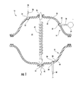
- Fig. 1 shows a cross-section of a system 10 for heat treating an alloy steel component according to one embodiment of the present invention.
- the system 10 includes a first enclosure 14 and a complimentary second enclosure 16.
- the first and second enclosures 14, 16 may be made from any suitable material capable of withstanding continuous and cyclic temperatures up to approximately 1,300 degrees Fahrenheit.
- the first and second enclosures 14, 16 may be made from steel, alloy steel, fiberglass, or similar materials known to one of ordinary skill in the art.
- the first and second enclosures 14, 16 may be circular, square, oval, or any other suitable shape to accommodate the alloy steel component to be annealed.
- the length and width of the first and second enclosures 14, 16 may be selected to accommodate the portion of the alloy steel component to be annealed.
- Each enclosure 14, 16 includes an outer surface 18 and an inner surface 20. When installed around the portion of the alloy steel component to be annealed, the inner surfaces 20 define a cavity or chamber 22 between the enclosures 14, 16 and around the portion of the alloy steel component to be annealed.
- the first and second enclosures 14, 16 may further include gaskets 24, grommets, o-rings, or similar devices for creating an airtight seal and making the chamber 22 substantially airtight.
- the first and second enclosures 14, 16 may further include one or more ports to accommodate peripheral equipment.
- the first enclosure 14 may include a gas port 26 that provides a fluid communication between a supply of gas 28 and the first enclosure 14.
- the supply of gas 28 may connect to the gas port 26 through an isolation valve 30 to permit or prevent the flow of the gas to the first enclosure 14.
- the supply of gas 28 may provide any suitable gas for establishing a desired environment around the alloy steel component.
- the supply of gas 28 may provide inert gases, such as argon or nitrogen, to surround the alloy steel component during the annealing process.
- the inert gas environment may reduce oxidation or decarburization caused by ambient air in the chamber 22 during the annealing process.
- the first enclosure 14 may further include a vacuum port 32 to connect a vacuum pump 34 to the first enclosure 14.
- the vacuum pump 34 may be used to draw a vacuum on the chamber 22 defined by the first and second enclosures 14, 16.
- the vacuum port 32 may include an isolation valve 36 between the vacuum port 32 and the vacuum pump 34 to isolate the first enclosure 14 when the vacuum pump 34 is not in use.
- the second enclosure 16 may include a drain port 38 connected to an isolation valve 40.
- the drain port 38 may be used to drain or purge ambient air or gas from the chamber 22 during various stages of the annealing process.
- the location of the ports have been described with respect to the embodiment illustrated in Fig. 1 , it should be understood that in alternate embodiments the ports may be in either or both of the first and/or second enclosures 14, 16.
- the system 10 also includes an induction coil 42 or similar heating element that extends through the first and second enclosures 14, 16 into the chamber 22 defined by the first and second enclosures 14, 16.
- the induction coil 42 or other suitable heating element provides the heat source for heating the chamber 22 defined by the first and second enclosures 14, 16, thereby heating the portion of the alloy steel component to be annealed.
- the size of the induction coil 42 or suitable heating element depends on the size of the alloy steel component to be annealed and the desired heat up rate to be achieved.
- Openings 44 in the first and second enclosures 14, 16 may include gasket material 46, insulation, rubber, or similar materials to accommodate induction coils 42 or other suitable heating elements of various sizes and to provide a suitable seal between the induction coil 42 and the first and second enclosures 14, 16.
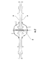
- Fig. 2 shows a cross-section of the system 10 shown in Fig. 1 installed on the alloy steel component to be annealed.
- the alloy steel component is a disk of a gas turbine rotor, and the system 10 is installed to enclose and anneal a bore 48 in the disk.
- the first and second enclosures 14, 16 are installed on opposite sides 50 of the alloy steel component.
- the chamber 22 between the enclosures 14, 16 and around the portion of the alloy steel component to be annealed is substantially airtight.
- the induction coil 42 or other suitable heating element extends through the first and second enclosures 14, 16 to provide localized heat to the chamber 22, and thus the portion of the alloy steel component to be annealed.
- the system 10 shown in Figs. 1 and 2 may be used for heat treating an alloy steel component in the following manner.
- the first enclosure 14 is placed against one side 50 of the alloy steel component to be annealed, and the second enclosure 16 is placed against the other side 50 of the alloy steel component to be annealed.
- the first and second sides 50 of the alloy steel component to be annealed may be opposite sides or adjacent sides that include the particular portion of the alloy steel component to be annealed.
- the chamber 22 defined by the first and second enclosures 14, 16 around the portion of the alloy steel component to be annealed is substantially airtight.
- the isolation valve 40 for the drain port 38 may be opened independently or in conjunction with the inert isolation valve 30 for the gas port 26 to purge the chamber 22 of air. If desired, the supply of gas 28 may provide inert gas or other medium to the chamber 22. In still further applications, the isolation valve 36 for the vacuum port 32 may be opened, and the vacuum pump 34 may be operated to draw a vacuum on the chamber 22.
- the induction coil 42 or other suitable heating element may then be energized to heat the substantially airtight chamber 22 to at least 1,000 degrees Fahrenheit to anneal the local portion of the alloy steel component.
- the induction coil 42 or other suitable heating element may heat the substantially airtight chamber at rates exceeding 500 degrees Fahrenheit per hour, and in some particular embodiments greater than 1,000 degrees Fahrenheit per hour.
- the temperature may then be maintained, preferably between 1,000 and 1,200 degrees Fahrenheit, for a suitable time to effect the desired annealing of the alloy steel component.
- suitable annealing may be accomplished by maintaining the temperature of the substantially airtight chamber 22 above 1,000 degrees Fahrenheit for at least 1 to 2 hours per inch thickness of the alloy steel component.
- the induction coil 42 or other suitable heating element may be de-energized to allow the alloy steel component to cool to room temperature.
- the isolation valves 30, 40 for the gas port 26 and/or the drain port 38 may be opened to allow cooling air and/or inert gas to flow through the chamber 22 to achieve a desired cool down rate of the alloy steel component to minimize any temperature embrittlement as the alloy steel component cools down.
- Higher cooling rates are preferred as the temperature of the alloy steel component decreases between 1,000 degrees and 700 degrees Fahrenheit to reduce the opportunity for the allow steel component to experience temperature embrittlement at these temperatures, thus negating some of the effects of the annealing process.
- cooling air may be regulated to achieve a cool down rate of 100 to 150 degrees Fahrenheit per hour until the temperature of the alloy steel component is less than approximately 700° F. Once the temperature of the alloy steel component is less than approximately 700° F, a slower cool down rate may be used until the alloy steel component reaches room temperature.
- the temperature of the chamber 22 and/or alloy steel component to be annealed may be carefully monitored during the annealing process.
- a thermocouple, pyrometer, resistance temperature detector, infrared laser, or similar instrument may be installed in the chamber 22 or against the local portion of the alloy steel component to be annealed to monitor the temperature, heat up rate, and cool down rate of the system 10.
- Fig. 3 shows an anticipated temperature profile for the system 10 during the annealing process.
- the induction coil 42 or other suitable heating element maintains the temperature in the substantially airtight chamber 22 at the desired temperature to effect annealing of the localized portion of the alloy steel component. Due to the localized heating provided by the induction coil 42 or other suitable heating element, the temperature rapidly decreases outside of the chamber 22, as shown by the decreasing temperature curve in Fig. 3 . As a result, the system 10 and method of the present invention does not distort or create residual stresses in the remainder of the alloy steel component outside of the chamber 22.
- the system 10 and methods described in the present invention allow for local areas of alloy steel component to be annealed, thereby restoring the fracture toughness of the alloy steel to approach or equal the original fracture toughness of the designed component.
- the system 10 and method allow the alloy steel component to be annealed in place or with minor disassembly, avoiding the need for larger chambers and reducing the amount of time that the commercial equipment is inoperable.
- the localized heat treatment of the alloy steel component reduces any distortion or residual stresses that may be created by heat treating the entire alloy steel component.
- the alloy steel components to be annealed may be treated individually or in a batch process.
- the rotor disk shown in Fig. 2 may be individually treated, or it may be treated partially stacked with other rotor disks.
- Fig. 2 shows the system 10 treating the bore 48 through the rotor disk, the system 10 may be readily adapted to enclose other portions of the rotor disk, such as bolt holes or other surfaces.
Landscapes
- Chemical & Material Sciences (AREA)
- Engineering & Computer Science (AREA)
- Physics & Mathematics (AREA)
- Thermal Sciences (AREA)
- Crystallography & Structural Chemistry (AREA)
- Mechanical Engineering (AREA)
- Materials Engineering (AREA)
- Metallurgy (AREA)
- Organic Chemistry (AREA)
- Heat Treatment Of Articles (AREA)
- Furnace Details (AREA)
- Heat Treatment Of Strip Materials And Filament Materials (AREA)
Abstract
Description
- The present invention generally involves systems and methods for annealing alloy steel components. In particular, the present invention describes and enables systems and methods for heat treating a portion of alloy steel components.
- Alloy steel is a combination of iron and up to 50% by weight of alloying elements such as nickel, chromium, molybdenum, manganese, vanadium, silicon, and boron. Alloy steels have greater strength, hardness, hot hardness, wear resistance, hardenability, and/or toughness compared to carbon steel. Alloy steels are further characterized by the amount of alloy added, with low alloy steels typically less than 2% to 4% by weight alloying, and high alloy steels having greater than 4% by weight alloying.
- Examples of alloy steels used in commercial applications include NiCrMoV and CrMoV alloy steels. For example, NiCrMoV and CrMoV alloy steels are often included in shafts, flanges, wheels, and disks included in a gas turbine. Heat treatment of these and other alloy steels is typically required to improve the strength, hardness, wear resistance, and/or toughness characteristics of the alloy steels compared to carbon steel.
- Gas turbine components typically operate in an environment of more than 600° F for extended periods of time. Prolonged exposure of alloy steels to high operating temperatures results in thermal embrittlement of the alloy steel, particularly at or near the surface of the alloy steel. For example, thermal embrittlement is commonly experienced around bores and/or bolt holes after prolonged operations at high temperatures. The thermal embrittlement produces slight micro-structural changes in the alloy steel that reduce the fracture toughness of the alloy steel and limit the service life of the alloy steel components. The service life of alloy steel components may be determined according to various metrics, such as the amount of time that the alloy steel component is exposed to high temperatures or a decrease in the fracture toughness and/or fracture appearance transition temperature (FATT) of the alloy steel component. Any of these parameters, or others, may be used to predict the onset of thermal embrittlement which may result in excessive crack formation and/or propagation.
- Alloy steel components that have experienced thermal embrittlement due to prolonged exposure to high temperature environments may be annealed using heat treatment methods known in the art. For example, the alloy steel components may be disassembled or removed and placed in a suitable chamber to heat the alloy steel components. However, the size of the alloy steel components often requires a correspondingly large chamber. In addition, removal and disassembly of the alloy steel components is time consuming, expensive, and results in extended maintenance periods during which the commercial equipment is not available for operation.
- Therefore the need exists for an improved system and method for annealing alloy steel components. Ideally, the improved system and method may anneal localized areas of the alloy steel components to reduce the time and cost associated with the annealing process, thereby reducing the amount of time that the commercial equipment is inoperable.
- Aspects and advantages of the invention are set forth below in the following description, or may be obvious from the description, or may be learned through practice of the invention.
- One embodiment of the present invention is a system for heat treating an alloy steel component. The system includes a first enclosure and a second enclosure opposed to the first enclosure. The first and second enclosures define a chamber around only a portion of the alloy steel component. The system further includes a heating element in the chamber to heat the portion of the alloy steel component.
- Another embodiment of the present invention is a method for heat treating an alloy steel component. The method includes placing a first enclosure against a first side of the alloy steel component and placing a second enclosure against a second side of the alloy steel component. The method further includes creating a substantially airtight chamber around only a portion of the alloy steel component between the first and second enclosures and heating the portion of the alloy steel component inside the substantially airtight chamber.
- Those of ordinary skill in the art will better appreciate the features and aspects of such embodiments, and others, upon review of the specification.
- A full and enabling disclosure of the present invention, including the best mode thereof to one skilled in the art, is set forth more particularly in the remainder of the specification by way of example, including reference to the accompanying figures, in which:
-
Fig. 1 shows a cross-section of a system for annealing alloy steel components according to one embodiment of the present invention; -
Fig. 2 shows the embodiment shown inFig. 1 installed around an alloy steel component; and -
Fig. 3 shows an anticipated temperature profile during the annealing process. - Reference will now be made in detail to present embodiments of the invention, one or more examples of which are illustrated in the accompanying drawings. The detailed description uses numerical and letter designations to refer to features in the drawings. Like or similar designations in the drawings and description have been used to refer to like or similar parts of the invention.
- Each example is provided by way of explanation of the invention, not limitation of the invention. In fact, it will be apparent to those skilled in the art that modifications and variations can be made in the present invention without departing from the scope or spirit thereof. For instance, features illustrated or described as part of one embodiment may be used on another embodiment to yield a still further embodiment. Thus, it is intended that the present invention covers such modifications and variations as come within the scope of the appended claims and their equivalents.
-
Fig. 1 shows a cross-section of asystem 10 for heat treating an alloy steel component according to one embodiment of the present invention. As shown, thesystem 10 includes afirst enclosure 14 and a complimentarysecond enclosure 16. The first andsecond enclosures second enclosures second enclosures second enclosures - Each
enclosure outer surface 18 and aninner surface 20. When installed around the portion of the alloy steel component to be annealed, theinner surfaces 20 define a cavity orchamber 22 between theenclosures second enclosures gaskets 24, grommets, o-rings, or similar devices for creating an airtight seal and making thechamber 22 substantially airtight. - The first and
second enclosures Fig. 1 , thefirst enclosure 14 may include agas port 26 that provides a fluid communication between a supply ofgas 28 and thefirst enclosure 14. The supply ofgas 28 may connect to thegas port 26 through anisolation valve 30 to permit or prevent the flow of the gas to thefirst enclosure 14. The supply ofgas 28 may provide any suitable gas for establishing a desired environment around the alloy steel component. For example, the supply ofgas 28 may provide inert gases, such as argon or nitrogen, to surround the alloy steel component during the annealing process. The inert gas environment may reduce oxidation or decarburization caused by ambient air in thechamber 22 during the annealing process. - The
first enclosure 14 may further include avacuum port 32 to connect avacuum pump 34 to thefirst enclosure 14. Thevacuum pump 34 may be used to draw a vacuum on thechamber 22 defined by the first andsecond enclosures vacuum port 32 may include anisolation valve 36 between thevacuum port 32 and thevacuum pump 34 to isolate thefirst enclosure 14 when thevacuum pump 34 is not in use. - As further shown in
Fig. 1 , thesecond enclosure 16 may include adrain port 38 connected to anisolation valve 40. Thedrain port 38 may be used to drain or purge ambient air or gas from thechamber 22 during various stages of the annealing process. Although the location of the ports have been described with respect to the embodiment illustrated inFig. 1 , it should be understood that in alternate embodiments the ports may be in either or both of the first and/orsecond enclosures - The
system 10 also includes aninduction coil 42 or similar heating element that extends through the first andsecond enclosures chamber 22 defined by the first andsecond enclosures induction coil 42 or other suitable heating element provides the heat source for heating thechamber 22 defined by the first andsecond enclosures induction coil 42 or suitable heating element depends on the size of the alloy steel component to be annealed and the desired heat up rate to be achieved.Openings 44 in the first andsecond enclosures gasket material 46, insulation, rubber, or similar materials to accommodateinduction coils 42 or other suitable heating elements of various sizes and to provide a suitable seal between theinduction coil 42 and the first andsecond enclosures -
Fig. 2 shows a cross-section of thesystem 10 shown inFig. 1 installed on the alloy steel component to be annealed. In this illustration, the alloy steel component is a disk of a gas turbine rotor, and thesystem 10 is installed to enclose and anneal abore 48 in the disk. As shown inFig. 2 , the first andsecond enclosures opposite sides 50 of the alloy steel component. As a result, thechamber 22 between theenclosures induction coil 42 or other suitable heating element extends through the first andsecond enclosures chamber 22, and thus the portion of the alloy steel component to be annealed. - The
system 10 shown inFigs. 1 and2 may be used for heat treating an alloy steel component in the following manner. Thefirst enclosure 14 is placed against oneside 50 of the alloy steel component to be annealed, and thesecond enclosure 16 is placed against theother side 50 of the alloy steel component to be annealed. The first andsecond sides 50 of the alloy steel component to be annealed may be opposite sides or adjacent sides that include the particular portion of the alloy steel component to be annealed. Thechamber 22 defined by the first andsecond enclosures - The
isolation valve 40 for thedrain port 38 may be opened independently or in conjunction with theinert isolation valve 30 for thegas port 26 to purge thechamber 22 of air. If desired, the supply ofgas 28 may provide inert gas or other medium to thechamber 22. In still further applications, theisolation valve 36 for thevacuum port 32 may be opened, and thevacuum pump 34 may be operated to draw a vacuum on thechamber 22. - The
induction coil 42 or other suitable heating element may then be energized to heat the substantiallyairtight chamber 22 to at least 1,000 degrees Fahrenheit to anneal the local portion of the alloy steel component. Theinduction coil 42 or other suitable heating element may heat the substantially airtight chamber at rates exceeding 500 degrees Fahrenheit per hour, and in some particular embodiments greater than 1,000 degrees Fahrenheit per hour. The temperature may then be maintained, preferably between 1,000 and 1,200 degrees Fahrenheit, for a suitable time to effect the desired annealing of the alloy steel component. For example, suitable annealing may be accomplished by maintaining the temperature of the substantiallyairtight chamber 22 above 1,000 degrees Fahrenheit for at least 1 to 2 hours per inch thickness of the alloy steel component. - After the annealing temperature has been maintained in the substantially
airtight chamber 22 for the desired amount of time, theinduction coil 42 or other suitable heating element may be de-energized to allow the alloy steel component to cool to room temperature. Theisolation valves gas port 26 and/or thedrain port 38 may be opened to allow cooling air and/or inert gas to flow through thechamber 22 to achieve a desired cool down rate of the alloy steel component to minimize any temperature embrittlement as the alloy steel component cools down. Higher cooling rates are preferred as the temperature of the alloy steel component decreases between 1,000 degrees and 700 degrees Fahrenheit to reduce the opportunity for the allow steel component to experience temperature embrittlement at these temperatures, thus negating some of the effects of the annealing process. For example, cooling air may be regulated to achieve a cool down rate of 100 to 150 degrees Fahrenheit per hour until the temperature of the alloy steel component is less than approximately 700° F. Once the temperature of the alloy steel component is less than approximately 700° F, a slower cool down rate may be used until the alloy steel component reaches room temperature. - The temperature of the
chamber 22 and/or alloy steel component to be annealed may be carefully monitored during the annealing process. For example, a thermocouple, pyrometer, resistance temperature detector, infrared laser, or similar instrument may be installed in thechamber 22 or against the local portion of the alloy steel component to be annealed to monitor the temperature, heat up rate, and cool down rate of thesystem 10. -
Fig. 3 shows an anticipated temperature profile for thesystem 10 during the annealing process. As shown inFig. 3 , theinduction coil 42 or other suitable heating element maintains the temperature in the substantiallyairtight chamber 22 at the desired temperature to effect annealing of the localized portion of the alloy steel component. Due to the localized heating provided by theinduction coil 42 or other suitable heating element, the temperature rapidly decreases outside of thechamber 22, as shown by the decreasing temperature curve inFig. 3 . As a result, thesystem 10 and method of the present invention does not distort or create residual stresses in the remainder of the alloy steel component outside of thechamber 22. - The
system 10 and methods described in the present invention allow for local areas of alloy steel component to be annealed, thereby restoring the fracture toughness of the alloy steel to approach or equal the original fracture toughness of the designed component. Thesystem 10 and method allow the alloy steel component to be annealed in place or with minor disassembly, avoiding the need for larger chambers and reducing the amount of time that the commercial equipment is inoperable. In addition, the localized heat treatment of the alloy steel component reduces any distortion or residual stresses that may be created by heat treating the entire alloy steel component. - The alloy steel components to be annealed may be treated individually or in a batch process. For example, the rotor disk shown in
Fig. 2 may be individually treated, or it may be treated partially stacked with other rotor disks. AlthoughFig. 2 shows thesystem 10 treating thebore 48 through the rotor disk, thesystem 10 may be readily adapted to enclose other portions of the rotor disk, such as bolt holes or other surfaces. - This written description uses examples to disclose the invention, including the best mode, and also to enable any person skilled in the art to practice the invention, including making and using any devices or systems and performing any incorporated methods. The patentable scope of the invention is defined by the claims, and may include other examples that occur to those skilled in the art. Such other examples are intended to be within the scope of the claims if they include structural elements that do not differ from the literal language of the claims, or if they include equivalent structural elements with insubstantial differences from the literal languages of the claims.
Claims (15)
- A system (10) for heat treating an alloy steel component, comprising:a. a first enclosure (14);b. a second enclosure (16) opposed to the first enclosure (14), wherein the first and second enclosures define a chamber (22) around only a portion of the alloy steel component; andc. a heating element (42) in the chamber (22) to heat the portion of the alloy steel component.
- The system (10) for heat treating an alloy steel component as in claim 1, further including a supply of inert gas (28) connected to at least one of the first enclosure (14) or the second enclosure (16).
- The system (10) for heat treating an alloy steel component as in any of claims 1 or 2, further including at least one port (25) through at least one of the first enclosure (14) or the second enclosure (16).
- The system (10) for heat treating an alloy steel component as in any of claims 1-3, further including at least one drain (38) through at least one of the first enclosure (14) or the second enclosure (16).
- The system (10) for heat treating an alloy steel component as in any of claims 1-4, further including a vacuum pump (34) connected to at least one of the first enclosure (14) or the second enclosure (16).
- A method for heat treating an alloy steel component, comprising:a. placing a first enclosure (14) against a first side (50) of the alloy steel component;b. placing a second enclosure (16) against a second side (50) of the alloy steel component;c. creating a substantially airtight chamber (22) around only a portion of the alloy steel component between the first and second enclosures (14, 16); andd. heating the portion of the alloy steel component inside the substantially airtight chamber (22).
- The method for heat treating an alloy steel component as in claim 6, wherein the second side is opposite the first side.
- The method for heat treating an alloy steel component as in claim 6 or 7, further including inserting an induction coil (42) into the substantially airtight chamber (22).
- The method for heating treating an alloy steel component as in any of claims 6 to 8, further including maintaining the temperature of the substantially airtight chamber above 1,000 degrees Fahrenheit for at least 1 hour per inch thickness of the alloy steel component.
- The method for heat treating an alloy steel component as in claim 9, further including maintaining the temperature of the substantially airtight chamber above 1,000 degrees Fahrenheit for at least 1 hour per inch thickness of the alloy steel component.
- The method for heat treating an alloy steel component as in claim 9, further including cooling the alloy steel component at a rate of approximately 100 to 150 degrees Fahrenheit per hour until a temperature of the alloy steel component is less than approximately 700 degrees Fahrenheit.
- The method for heating treating an alloy steel component as in any of claims 6 to 11, further including heating the substantially airtight chamber (22) to at least 1,000 degrees Fahrenheit at a rate of at least 500 degrees Fahrenheit per hour.
- The method for heat treating an alloy steel component as in any of claims 6 to 12, further including purging the substantially airtight chamber of air.
- The method for heating treating an alloy steel component as in any of claims 6 to 13, further including flowing an inert gas (28) into the substantially airtight chamber (22).
- The method for heat treating an alloy steel component as in any of claims 6 to 14, further including creating a vacuum in the substantially airtight chamber (22).
Applications Claiming Priority (1)
| Application Number | Priority Date | Filing Date | Title |
|---|---|---|---|
| US12/688,950 US8512629B2 (en) | 2010-01-18 | 2010-01-18 | System and method for annealing alloy steel components |
Publications (3)
| Publication Number | Publication Date |
|---|---|
| EP2360284A2 true EP2360284A2 (en) | 2011-08-24 |
| EP2360284A3 EP2360284A3 (en) | 2016-07-27 |
| EP2360284B1 EP2360284B1 (en) | 2020-04-01 |
Family
ID=44115541
Family Applications (1)
| Application Number | Title | Priority Date | Filing Date |
|---|---|---|---|
| EP11151134.1A Active EP2360284B1 (en) | 2010-01-18 | 2011-01-17 | System and method for annealing alloy steel components |
Country Status (4)
| Country | Link |
|---|---|
| US (1) | US8512629B2 (en) |
| EP (1) | EP2360284B1 (en) |
| JP (1) | JP5844047B2 (en) |
| CN (1) | CN102127623B (en) |
Families Citing this family (3)
| Publication number | Priority date | Publication date | Assignee | Title |
|---|---|---|---|---|
| US9981168B2 (en) | 2013-05-06 | 2018-05-29 | Acushnet Company | Supported iron set |
| US9718119B2 (en) * | 2013-05-06 | 2017-08-01 | Acushnet Company | Method of forming an iron set |
| DK177974B1 (en) * | 2013-09-09 | 2015-02-09 | Broen As | Plant and method for relaxing annealing of a workpiece comprising heat-sensitive parts, as well as relaxation-annealed workpiece |
Family Cites Families (15)
| Publication number | Priority date | Publication date | Assignee | Title |
|---|---|---|---|---|
| US2367715A (en) * | 1943-12-18 | 1945-01-23 | Chapman Everett | Method and apparatus for metal treatment and fabrication |
| US2812272A (en) * | 1954-08-02 | 1957-11-05 | Ohio Commw Eng Co | Apparatus and method for the production of metallized materials |
| US3156807A (en) * | 1961-10-27 | 1964-11-10 | North American Aviation Inc | Induction heating method and means |
| JPS50101207A (en) * | 1974-01-14 | 1975-08-11 | ||
| SE420218B (en) * | 1978-08-22 | 1981-09-21 | Asea Atom Ab | DEVICE FOR HEAT TREATMENT OF A LONG-TERM PLATE |
| JPS61295322A (en) * | 1985-06-22 | 1986-12-26 | Aichi Electric Co Ltd | Annealing device for rolled core |
| JPS62290826A (en) * | 1986-06-11 | 1987-12-17 | Hitachi Cable Ltd | Method for replacing gas in pipe during annealing of coiled pipe |
| JPH08134548A (en) * | 1994-11-07 | 1996-05-28 | Miyaden:Kk | Quenching of chip saw base metal of circular saw and apparatus therefor |
| EP0862965A1 (en) * | 1997-03-07 | 1998-09-09 | Daido Tokushuko Kabushiki Kaisha | Gas shielding apparatus and gas shielding method |
| US6702980B2 (en) * | 2002-04-30 | 2004-03-09 | Martinrea Industries, Inc. | Annealing apparatus |
| US8058591B2 (en) * | 2007-03-30 | 2011-11-15 | United Technologies Corp. | Systems and methods for providing localized heat treatment of gas turbine components |
| JP5162949B2 (en) * | 2007-04-20 | 2013-03-13 | 新日鐵住金株式会社 | Induction heating furnace |
| US7977611B2 (en) * | 2007-07-19 | 2011-07-12 | United Technologies Corporation | Systems and methods for providing localized heat treatment of metal components |
| US20090057301A1 (en) * | 2007-08-28 | 2009-03-05 | Jean Lovens | Electric induction heating apparatus with fluid medium flow through |
| US8141249B2 (en) * | 2007-10-11 | 2012-03-27 | United Technologies Corporation | Heat treating apparatus and method of using same |
-
2010
- 2010-01-18 US US12/688,950 patent/US8512629B2/en active Active
-
2011
- 2011-01-17 JP JP2011006625A patent/JP5844047B2/en not_active Expired - Fee Related
- 2011-01-17 EP EP11151134.1A patent/EP2360284B1/en active Active
- 2011-01-18 CN CN201110027778.8A patent/CN102127623B/en active Active
Non-Patent Citations (1)
| Title |
|---|
| None |
Also Published As
| Publication number | Publication date |
|---|---|
| EP2360284B1 (en) | 2020-04-01 |
| CN102127623A (en) | 2011-07-20 |
| JP5844047B2 (en) | 2016-01-13 |
| CN102127623B (en) | 2014-12-10 |
| EP2360284A3 (en) | 2016-07-27 |
| US20110174419A1 (en) | 2011-07-21 |
| US8512629B2 (en) | 2013-08-20 |
| JP2011144453A (en) | 2011-07-28 |
Similar Documents
| Publication | Publication Date | Title |
|---|---|---|
| US8512629B2 (en) | System and method for annealing alloy steel components | |
| KR102464067B1 (en) | Device for individual quench hardening of technical equipment components | |
| JP5577573B2 (en) | Vacuum carburizing method and vacuum carburizing apparatus | |
| KR20060047713A (en) | Carburized Nitride Quenched Martensite Stainless Steel | |
| RU2015128019A (en) | GROUP OF EQUIPMENT FOR THERMAL TREATMENT OF SEAMLESS STEEL PIPE OR PIPELINE AND METHOD FOR PRODUCING PIPE OR PIPELINE FROM HIGH STRENGTH STAINLESS STEEL | |
| EP3144398A1 (en) | Method of manufacturing rotor to be used for steam turbine | |
| MX2022010189A (en) | METHOD FOR PREPARING GRAIN ORIENTED SILICON STEEL WITHOUT GLASS AND PRODUCT THEREOF. | |
| JP5572251B1 (en) | Surface hardening treatment method and surface hardening treatment apparatus for steel members | |
| TWI614462B (en) | Apparatus and method for shielding a controlled pressure environment | |
| CN111455147A (en) | A kind of heat treatment method of Cronidur 30 stainless steel parts | |
| CN1032568A (en) | Surface hardening technology and improved structure of steam inlet cover of steam turbine | |
| CN103014262A (en) | Carbon tool steel spheroidizing annealing process | |
| US11840765B2 (en) | Nitriding process for carburizing ferrium steels | |
| US9242313B2 (en) | Welding furnace and viewport assembly | |
| EP3168313B1 (en) | Low pressure induction carburization | |
| US20120279619A1 (en) | Treatment for preventing stress corrosion cracking | |
| JP2765609B2 (en) | How to purge bell type coil annealing furnace | |
| JP2001342519A (en) | Method for preventing austenitic stainless steel members from distortion | |
| CN109402365A (en) | A kind of conditioning treatment process solving T/P91, T/P92 mixed grain structure | |
| JP5817173B2 (en) | Gas quenching method | |
| JP2024171176A (en) | Intermediate annealing heat retention tank and intermediate annealing method for hot-worked steel | |
| Nell et al. | New gas nitriding technique using the interior of the nitrided pressure vessel as the process chamber | |
| TH1901007353A (en) | Methods for manufacturing steel parts and related steel parts. | |
| Ben-Hamida et al. | Use of new types of large and middle size vacuum batch furnaces for heat treatment of moulds and dies | |
| UA101325U (en) | Method for thermal processing of castings made of high-chromium alloyed iron |
Legal Events
| Date | Code | Title | Description |
|---|---|---|---|
| PUAI | Public reference made under article 153(3) epc to a published international application that has entered the european phase |
Free format text: ORIGINAL CODE: 0009012 |
|
| AK | Designated contracting states |
Kind code of ref document: A2 Designated state(s): AL AT BE BG CH CY CZ DE DK EE ES FI FR GB GR HR HU IE IS IT LI LT LU LV MC MK MT NL NO PL PT RO RS SE SI SK SM TR |
|
| AX | Request for extension of the european patent |
Extension state: BA ME |
|
| PUAL | Search report despatched |
Free format text: ORIGINAL CODE: 0009013 |
|
| AK | Designated contracting states |
Kind code of ref document: A3 Designated state(s): AL AT BE BG CH CY CZ DE DK EE ES FI FR GB GR HR HU IE IS IT LI LT LU LV MC MK MT NL NO PL PT RO RS SE SI SK SM TR |
|
| AX | Request for extension of the european patent |
Extension state: BA ME |
|
| RIC1 | Information provided on ipc code assigned before grant |
Ipc: C21D 1/74 20060101ALI20160621BHEP Ipc: C21D 1/42 20060101ALI20160621BHEP Ipc: C21D 9/00 20060101AFI20160621BHEP Ipc: C21D 1/773 20060101ALI20160621BHEP Ipc: C21D 1/76 20060101ALI20160621BHEP |
|
| STAA | Information on the status of an ep patent application or granted ep patent |
Free format text: STATUS: REQUEST FOR EXAMINATION WAS MADE |
|
| 17P | Request for examination filed |
Effective date: 20170127 |
|
| RBV | Designated contracting states (corrected) |
Designated state(s): AL AT BE BG CH CY CZ DE DK EE ES FI FR GB GR HR HU IE IS IT LI LT LU LV MC MK MT NL NO PL PT RO RS SE SI SK SM TR |
|
| STAA | Information on the status of an ep patent application or granted ep patent |
Free format text: STATUS: EXAMINATION IS IN PROGRESS |
|
| 17Q | First examination report despatched |
Effective date: 20170602 |
|
| GRAP | Despatch of communication of intention to grant a patent |
Free format text: ORIGINAL CODE: EPIDOSNIGR1 |
|
| STAA | Information on the status of an ep patent application or granted ep patent |
Free format text: STATUS: GRANT OF PATENT IS INTENDED |
|
| INTG | Intention to grant announced |
Effective date: 20191024 |
|
| GRAS | Grant fee paid |
Free format text: ORIGINAL CODE: EPIDOSNIGR3 |
|
| GRAA | (expected) grant |
Free format text: ORIGINAL CODE: 0009210 |
|
| STAA | Information on the status of an ep patent application or granted ep patent |
Free format text: STATUS: THE PATENT HAS BEEN GRANTED |
|
| AK | Designated contracting states |
Kind code of ref document: B1 Designated state(s): AL AT BE BG CH CY CZ DE DK EE ES FI FR GB GR HR HU IE IS IT LI LT LU LV MC MK MT NL NO PL PT RO RS SE SI SK SM TR |
|
| REG | Reference to a national code |
Ref country code: GB Ref legal event code: FG4D |
|
| REG | Reference to a national code |
Ref country code: AT Ref legal event code: REF Ref document number: 1251407 Country of ref document: AT Kind code of ref document: T Effective date: 20200415 Ref country code: CH Ref legal event code: EP |
|
| REG | Reference to a national code |
Ref country code: DE Ref legal event code: R096 Ref document number: 602011065930 Country of ref document: DE |
|
| REG | Reference to a national code |
Ref country code: IE Ref legal event code: FG4D |
|
| PG25 | Lapsed in a contracting state [announced via postgrant information from national office to epo] |
Ref country code: BG Free format text: LAPSE BECAUSE OF FAILURE TO SUBMIT A TRANSLATION OF THE DESCRIPTION OR TO PAY THE FEE WITHIN THE PRESCRIBED TIME-LIMIT Effective date: 20200701 |
|
| REG | Reference to a national code |
Ref country code: NL Ref legal event code: MP Effective date: 20200401 |
|
| REG | Reference to a national code |
Ref country code: LT Ref legal event code: MG4D |
|
| PG25 | Lapsed in a contracting state [announced via postgrant information from national office to epo] |
Ref country code: PT Free format text: LAPSE BECAUSE OF FAILURE TO SUBMIT A TRANSLATION OF THE DESCRIPTION OR TO PAY THE FEE WITHIN THE PRESCRIBED TIME-LIMIT Effective date: 20200817 Ref country code: LT Free format text: LAPSE BECAUSE OF FAILURE TO SUBMIT A TRANSLATION OF THE DESCRIPTION OR TO PAY THE FEE WITHIN THE PRESCRIBED TIME-LIMIT Effective date: 20200401 Ref country code: NL Free format text: LAPSE BECAUSE OF FAILURE TO SUBMIT A TRANSLATION OF THE DESCRIPTION OR TO PAY THE FEE WITHIN THE PRESCRIBED TIME-LIMIT Effective date: 20200401 Ref country code: SE Free format text: LAPSE BECAUSE OF FAILURE TO SUBMIT A TRANSLATION OF THE DESCRIPTION OR TO PAY THE FEE WITHIN THE PRESCRIBED TIME-LIMIT Effective date: 20200401 Ref country code: GR Free format text: LAPSE BECAUSE OF FAILURE TO SUBMIT A TRANSLATION OF THE DESCRIPTION OR TO PAY THE FEE WITHIN THE PRESCRIBED TIME-LIMIT Effective date: 20200702 Ref country code: NO Free format text: LAPSE BECAUSE OF FAILURE TO SUBMIT A TRANSLATION OF THE DESCRIPTION OR TO PAY THE FEE WITHIN THE PRESCRIBED TIME-LIMIT Effective date: 20200701 Ref country code: CZ Free format text: LAPSE BECAUSE OF FAILURE TO SUBMIT A TRANSLATION OF THE DESCRIPTION OR TO PAY THE FEE WITHIN THE PRESCRIBED TIME-LIMIT Effective date: 20200401 Ref country code: FI Free format text: LAPSE BECAUSE OF FAILURE TO SUBMIT A TRANSLATION OF THE DESCRIPTION OR TO PAY THE FEE WITHIN THE PRESCRIBED TIME-LIMIT Effective date: 20200401 Ref country code: IS Free format text: LAPSE BECAUSE OF FAILURE TO SUBMIT A TRANSLATION OF THE DESCRIPTION OR TO PAY THE FEE WITHIN THE PRESCRIBED TIME-LIMIT Effective date: 20200801 |
|
| REG | Reference to a national code |
Ref country code: AT Ref legal event code: MK05 Ref document number: 1251407 Country of ref document: AT Kind code of ref document: T Effective date: 20200401 |
|
| PG25 | Lapsed in a contracting state [announced via postgrant information from national office to epo] |
Ref country code: RS Free format text: LAPSE BECAUSE OF FAILURE TO SUBMIT A TRANSLATION OF THE DESCRIPTION OR TO PAY THE FEE WITHIN THE PRESCRIBED TIME-LIMIT Effective date: 20200401 Ref country code: LV Free format text: LAPSE BECAUSE OF FAILURE TO SUBMIT A TRANSLATION OF THE DESCRIPTION OR TO PAY THE FEE WITHIN THE PRESCRIBED TIME-LIMIT Effective date: 20200401 Ref country code: HR Free format text: LAPSE BECAUSE OF FAILURE TO SUBMIT A TRANSLATION OF THE DESCRIPTION OR TO PAY THE FEE WITHIN THE PRESCRIBED TIME-LIMIT Effective date: 20200401 |
|
| PG25 | Lapsed in a contracting state [announced via postgrant information from national office to epo] |
Ref country code: AL Free format text: LAPSE BECAUSE OF FAILURE TO SUBMIT A TRANSLATION OF THE DESCRIPTION OR TO PAY THE FEE WITHIN THE PRESCRIBED TIME-LIMIT Effective date: 20200401 |
|
| REG | Reference to a national code |
Ref country code: DE Ref legal event code: R097 Ref document number: 602011065930 Country of ref document: DE |
|
| PG25 | Lapsed in a contracting state [announced via postgrant information from national office to epo] |
Ref country code: EE Free format text: LAPSE BECAUSE OF FAILURE TO SUBMIT A TRANSLATION OF THE DESCRIPTION OR TO PAY THE FEE WITHIN THE PRESCRIBED TIME-LIMIT Effective date: 20200401 Ref country code: SM Free format text: LAPSE BECAUSE OF FAILURE TO SUBMIT A TRANSLATION OF THE DESCRIPTION OR TO PAY THE FEE WITHIN THE PRESCRIBED TIME-LIMIT Effective date: 20200401 Ref country code: RO Free format text: LAPSE BECAUSE OF FAILURE TO SUBMIT A TRANSLATION OF THE DESCRIPTION OR TO PAY THE FEE WITHIN THE PRESCRIBED TIME-LIMIT Effective date: 20200401 Ref country code: DK Free format text: LAPSE BECAUSE OF FAILURE TO SUBMIT A TRANSLATION OF THE DESCRIPTION OR TO PAY THE FEE WITHIN THE PRESCRIBED TIME-LIMIT Effective date: 20200401 Ref country code: ES Free format text: LAPSE BECAUSE OF FAILURE TO SUBMIT A TRANSLATION OF THE DESCRIPTION OR TO PAY THE FEE WITHIN THE PRESCRIBED TIME-LIMIT Effective date: 20200401 Ref country code: AT Free format text: LAPSE BECAUSE OF FAILURE TO SUBMIT A TRANSLATION OF THE DESCRIPTION OR TO PAY THE FEE WITHIN THE PRESCRIBED TIME-LIMIT Effective date: 20200401 |
|
| PLBE | No opposition filed within time limit |
Free format text: ORIGINAL CODE: 0009261 |
|
| STAA | Information on the status of an ep patent application or granted ep patent |
Free format text: STATUS: NO OPPOSITION FILED WITHIN TIME LIMIT |
|
| PG25 | Lapsed in a contracting state [announced via postgrant information from national office to epo] |
Ref country code: SK Free format text: LAPSE BECAUSE OF FAILURE TO SUBMIT A TRANSLATION OF THE DESCRIPTION OR TO PAY THE FEE WITHIN THE PRESCRIBED TIME-LIMIT Effective date: 20200401 Ref country code: PL Free format text: LAPSE BECAUSE OF FAILURE TO SUBMIT A TRANSLATION OF THE DESCRIPTION OR TO PAY THE FEE WITHIN THE PRESCRIBED TIME-LIMIT Effective date: 20200401 |
|
| 26N | No opposition filed |
Effective date: 20210112 |
|
| PG25 | Lapsed in a contracting state [announced via postgrant information from national office to epo] |
Ref country code: SI Free format text: LAPSE BECAUSE OF FAILURE TO SUBMIT A TRANSLATION OF THE DESCRIPTION OR TO PAY THE FEE WITHIN THE PRESCRIBED TIME-LIMIT Effective date: 20200401 |
|
| PG25 | Lapsed in a contracting state [announced via postgrant information from national office to epo] |
Ref country code: MC Free format text: LAPSE BECAUSE OF FAILURE TO SUBMIT A TRANSLATION OF THE DESCRIPTION OR TO PAY THE FEE WITHIN THE PRESCRIBED TIME-LIMIT Effective date: 20200401 |
|
| REG | Reference to a national code |
Ref country code: CH Ref legal event code: PL |
|
| PG25 | Lapsed in a contracting state [announced via postgrant information from national office to epo] |
Ref country code: LU Free format text: LAPSE BECAUSE OF NON-PAYMENT OF DUE FEES Effective date: 20210117 |
|
| REG | Reference to a national code |
Ref country code: BE Ref legal event code: MM Effective date: 20210131 |
|
| PG25 | Lapsed in a contracting state [announced via postgrant information from national office to epo] |
Ref country code: CH Free format text: LAPSE BECAUSE OF NON-PAYMENT OF DUE FEES Effective date: 20210131 Ref country code: LI Free format text: LAPSE BECAUSE OF NON-PAYMENT OF DUE FEES Effective date: 20210131 |
|
| PG25 | Lapsed in a contracting state [announced via postgrant information from national office to epo] |
Ref country code: IE Free format text: LAPSE BECAUSE OF NON-PAYMENT OF DUE FEES Effective date: 20210117 |
|
| PG25 | Lapsed in a contracting state [announced via postgrant information from national office to epo] |
Ref country code: BE Free format text: LAPSE BECAUSE OF NON-PAYMENT OF DUE FEES Effective date: 20210131 |
|
| PG25 | Lapsed in a contracting state [announced via postgrant information from national office to epo] |
Ref country code: HU Free format text: LAPSE BECAUSE OF FAILURE TO SUBMIT A TRANSLATION OF THE DESCRIPTION OR TO PAY THE FEE WITHIN THE PRESCRIBED TIME-LIMIT; INVALID AB INITIO Effective date: 20110117 Ref country code: CY Free format text: LAPSE BECAUSE OF FAILURE TO SUBMIT A TRANSLATION OF THE DESCRIPTION OR TO PAY THE FEE WITHIN THE PRESCRIBED TIME-LIMIT Effective date: 20200401 |
|
| REG | Reference to a national code |
Ref country code: DE Ref legal event code: R082 Ref document number: 602011065930 Country of ref document: DE Ref country code: DE Ref legal event code: R081 Ref document number: 602011065930 Country of ref document: DE Owner name: GENERAL ELECTRIC TECHNOLOGY GMBH, CH Free format text: FORMER OWNER: GENERAL ELECTRIC COMPANY, SCHENECTADY, N.Y., US |
|
| REG | Reference to a national code |
Ref country code: GB Ref legal event code: 732E Free format text: REGISTERED BETWEEN 20240222 AND 20240228 |
|
| PG25 | Lapsed in a contracting state [announced via postgrant information from national office to epo] |
Ref country code: MK Free format text: LAPSE BECAUSE OF FAILURE TO SUBMIT A TRANSLATION OF THE DESCRIPTION OR TO PAY THE FEE WITHIN THE PRESCRIBED TIME-LIMIT Effective date: 20200401 |
|
| PG25 | Lapsed in a contracting state [announced via postgrant information from national office to epo] |
Ref country code: TR Free format text: LAPSE BECAUSE OF FAILURE TO SUBMIT A TRANSLATION OF THE DESCRIPTION OR TO PAY THE FEE WITHIN THE PRESCRIBED TIME-LIMIT Effective date: 20200401 |
|
| PG25 | Lapsed in a contracting state [announced via postgrant information from national office to epo] |
Ref country code: MT Free format text: LAPSE BECAUSE OF FAILURE TO SUBMIT A TRANSLATION OF THE DESCRIPTION OR TO PAY THE FEE WITHIN THE PRESCRIBED TIME-LIMIT Effective date: 20200401 |
|
| PGFP | Annual fee paid to national office [announced via postgrant information from national office to epo] |
Ref country code: GB Payment date: 20251220 Year of fee payment: 16 |
|
| PGFP | Annual fee paid to national office [announced via postgrant information from national office to epo] |
Ref country code: FR Payment date: 20251217 Year of fee payment: 16 |
|
| PGFP | Annual fee paid to national office [announced via postgrant information from national office to epo] |
Ref country code: DE Payment date: 20251217 Year of fee payment: 16 |
|
| PGFP | Annual fee paid to national office [announced via postgrant information from national office to epo] |
Ref country code: IT Payment date: 20260107 Year of fee payment: 16 |