EP2360029A1 - Spoke wheel - Google Patents
Spoke wheel Download PDFInfo
- Publication number
- EP2360029A1 EP2360029A1 EP11250129A EP11250129A EP2360029A1 EP 2360029 A1 EP2360029 A1 EP 2360029A1 EP 11250129 A EP11250129 A EP 11250129A EP 11250129 A EP11250129 A EP 11250129A EP 2360029 A1 EP2360029 A1 EP 2360029A1
- Authority
- EP
- European Patent Office
- Prior art keywords
- spoke
- rim
- receiving hole
- wheel
- hub
- Prior art date
- Legal status (The legal status is an assumption and is not a legal conclusion. Google has not performed a legal analysis and makes no representation as to the accuracy of the status listed.)
- Granted
Links
Images


Classifications
-
- B—PERFORMING OPERATIONS; TRANSPORTING
- B60—VEHICLES IN GENERAL
- B60B—VEHICLE WHEELS; CASTORS; AXLES FOR WHEELS OR CASTORS; INCREASING WHEEL ADHESION
- B60B1/00—Spoked wheels; Spokes thereof
- B60B1/02—Wheels with wire or other tension spokes
- B60B1/04—Attaching spokes to rim or hub
-
- B—PERFORMING OPERATIONS; TRANSPORTING
- B60—VEHICLES IN GENERAL
- B60B—VEHICLE WHEELS; CASTORS; AXLES FOR WHEELS OR CASTORS; INCREASING WHEEL ADHESION
- B60B1/00—Spoked wheels; Spokes thereof
- B60B1/02—Wheels with wire or other tension spokes
- B60B1/04—Attaching spokes to rim or hub
- B60B1/042—Attaching spokes to hub
-
- B—PERFORMING OPERATIONS; TRANSPORTING
- B60—VEHICLES IN GENERAL
- B60B—VEHICLE WHEELS; CASTORS; AXLES FOR WHEELS OR CASTORS; INCREASING WHEEL ADHESION
- B60B1/00—Spoked wheels; Spokes thereof
- B60B1/02—Wheels with wire or other tension spokes
- B60B1/04—Attaching spokes to rim or hub
- B60B1/043—Attaching spokes to rim
- B60B1/044—Attaching spokes to rim by the use of spoke nipples
-
- B—PERFORMING OPERATIONS; TRANSPORTING
- B60—VEHICLES IN GENERAL
- B60B—VEHICLE WHEELS; CASTORS; AXLES FOR WHEELS OR CASTORS; INCREASING WHEEL ADHESION
- B60B21/00—Rims
- B60B21/02—Rims characterised by transverse section
- B60B21/026—Rims characterised by transverse section the shape of rim well
-
- B—PERFORMING OPERATIONS; TRANSPORTING
- B60—VEHICLES IN GENERAL
- B60B—VEHICLE WHEELS; CASTORS; AXLES FOR WHEELS OR CASTORS; INCREASING WHEEL ADHESION
- B60B21/00—Rims
- B60B21/02—Rims characterised by transverse section
- B60B21/04—Rims characterised by transverse section with substantially radial flanges
-
- B—PERFORMING OPERATIONS; TRANSPORTING
- B60—VEHICLES IN GENERAL
- B60B—VEHICLE WHEELS; CASTORS; AXLES FOR WHEELS OR CASTORS; INCREASING WHEEL ADHESION
- B60B21/00—Rims
- B60B21/06—Rims characterised by means for attaching spokes, i.e. spoke seats
-
- B—PERFORMING OPERATIONS; TRANSPORTING
- B60—VEHICLES IN GENERAL
- B60B—VEHICLE WHEELS; CASTORS; AXLES FOR WHEELS OR CASTORS; INCREASING WHEEL ADHESION
- B60B21/00—Rims
- B60B21/06—Rims characterised by means for attaching spokes, i.e. spoke seats
- B60B21/064—Rims characterised by means for attaching spokes, i.e. spoke seats characterised by shape of spoke mounting holes, e.g. elliptical or triangular
-
- B—PERFORMING OPERATIONS; TRANSPORTING
- B60—VEHICLES IN GENERAL
- B60Y—INDEXING SCHEME RELATING TO ASPECTS CROSS-CUTTING VEHICLE TECHNOLOGY
- B60Y2200/00—Type of vehicle
- B60Y2200/10—Road Vehicles
- B60Y2200/12—Motorcycles, Trikes; Quads; Scooters
Definitions
- the present invention relates to a spoke wheel for use in motorcycles and the like and more specifically to a spoke wheel for use preferably for a tubeless tire.
- the spoke wheel of the invention is assembled by engaging retaining heads of wired spokes with a rim and by fastening the spokes by nipples in a hub.
- a wheel for use in motorcycles is composed of a hub mounted to a wheel axis, a rim mounted with a tire and spokes that connect the hub with the rim in general. While there are two kinds of wheels of a cast wheel in which the rim, spokes and hub are unitarily molded by means of casting and a spoke wheel (or more precisely a wired spoke wheel) in which the rim is connected with the hub by a large number of wired spokes, the invention relates to the spoke wheel.
- the spoke wheel can absorb shocks by the rim and spokes that are deformable and off-road motorcycles mostly adopt the spoke wheel.
- Each spoke has a retaining head at one end, a male screw portion at another end and a straight wired body portion between the head and the male screw portion and the spoke is fixed between the rim and the hub by retainably anchoring the head on the hub side and by fastening the male screw portion on the rim side by means of a nipple in general.
- a spoke wheel in which the spoke is connected between the rim and the hub by retainably anchoring the head to the rim and by fastening the male screw portion on the hub side by means of a nipple (see Patent Document 1 for example).
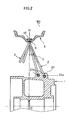
- a spoke wheel W2 for a tubeless tire in which a head portion 3 of a spoke 2' is retainably anchored to a hub 1 and the spoke 2' is fastened to a rim 5 through an intermediary of a nipple 6 as shown in FIG. 6 .
- the rim 5 has a projecting portion 9' formed circularly around the whole circumference of the rim 5 at a widthwise center part (drop portion or well portion) of the rim 5 so as to project in the radially inward direction of the wheel (referred to simply as the radially inward direction or a radially inside hereinafter) and to have a predetermined thickness.
- concave portions 10' and spoke receiving holes 11' are formed through the projecting portion 9' so that they have a predetermined thickness from the radially outside of the wheel (tire mounting side, referred to simply as the radially outside or radially outward direction hereinafter).
- the spoke wheel is assembled hermetically by fitting a rubber cap 12 into each concave portion 10' after fixing the spoke 2' by fittingly inserting the nipple 6 through the spoke receiving hole 11' (see Patent Document 2 for example).
- Patent Document 1 Japanese Patent Application Laid-open No. S60-161201
- Patent Document 2 Japanese Patent Application Laid-open No. 2000-301902
- a spoke wheel W3 in which the head of the spoke is retainably anchored - to the rim and the other end of the spoke is fastened to the hub by the nipple is arranged as follows. That is, a spoke receiving hole 11' is formed at the widthwise center part of the rim 5 so that a center line of the hole is aligned with a center line O-O extending from the radially outside to the center of the hub and so that a diameter d3 of the spoke receiving hole 11' is relatively larger than a diameter D3 of the spoke 2'.
- the spoke 2' has a head straight portion 2a' extending straightly by a predetermined length L3 from the head portion 3 and is curved from a curve starting portion C' by a predetermined curved angle ⁇ 3.
- the spoke then extends straightly to the hub. Accordingly, the head portion 3 of the spoke 2' butts against a stepped portion 15 of the spoke receiving hole 11' at two points A and B in the figure and the length L3 of the head straight portion 2a' to the curve starting portion C' is larger than a thickness h3 of the spoke receiving hole 11' of the rim 5 (L3 > h3). Still more, the head straight portion 2a' extends along the center line O-O so that it is inserted through the spoke receiving hole 11' without contacting with the surface of the hole. While the spoke 2' is pulled by the nipple on the hub side and is elastically deformed from a solid-line position to a broken-line position in FIG.
- the head portion 3 contacts at the two points A and B (denoted here as the two points even through there is a contact area having a predetermined length in a peripheral direction) of the stepped portion 15 and the spoke 2' will not contact with the surface of the spoke receiving hole 11' even if the tension is applied in general. It is noted that although there is a case when part of the spoke 2' contacts with the surface of the spoke receiving hole 11' due to variations and others of the spoke during its manufacturing or mounting process, an angle of contact thereof is small even if the spoke contacts with the surface of the hole because the head straight portion 2a' is longer than the thickness h3 of the rim.
- the spoke 2' is designed so that the head straight portion 2a' extends along the center line O-O and directions in which the spoke extend corresponding to a plane angle (see a in FIG. 1 ) and an elevation angle (see b in FIG. 2 ) are all defined by the predetermined curved angle ⁇ 3 described above, the curved angle is relatively large.
- the spoke receiving hole 11' through which the nipple 6 is inserted and retained must be formed in the rim 5.
- a diameter of the nipple 6 must be larger than a diameter of the spoke as far as it is screwed with a male screw portion of the spoke 2' and a length of a head of the nipple must be longer than a length of the head of the spoke. That is, the both diameter and depth of the spoke receiving hole 11' formed in the rim 5 cannot but be large.
- a diameter of the concave portion 10' is also enlarged to fit the rubber cap 12 on the radially outside of the receiving hole. That is, the width and thickness of the projecting portion 9' having the predetermined thickness to form these receiving hole 11' and concave portion 10' increase, causing an increase of weight of the spoke wheel.
- the spoke receiving hole 11' and the concave portion 10' concentrically formed with the receiving hole must be formed aslant with respect to the wheel center line by considering the elevation and plane angles in tensioning the spoke and works for forming the spoke receiving hole 11' and others are relatively cumbersome. Still more, because the spoke receiving hole 11' and the concave portion 10' must be formed aslant in the projecting portion 9, the width and thickness of the projecting portion must be increased, also causing the increase of weight of the spoke wheel.
- the invention aims at solving the abovementioned problems by providing a spoke wheel capable of anchoring a retaining head of a spoke by a spoke receiving hole of a rim with a relatively simple structure.
- a spoke wheel having a hub (1), a rim (5) and wired spokes (2) connecting the hub and the rim.
- Each spoke has a head portion (3) retainably anchored to a spoke receiving hole (11) formed in the rim and a male screw portion (4) fastened to the hub (1) through a nipple (6) and has the following characteristics. That is, the spoke receiving hole has a stepped portion (15) on the radially outside thereof and is formed in the rim (5) so that it is aligned with a wheel center line (O-O).
- the spoke (2) has also a head straight portion (2a) extending straightly from the head portion (3) to a curve starting portion (C) and a body portion (2b) curved at the curve starting portion with a predetermined angle ( ⁇ ) and extending toward the hub (1).
- the spoke (2) is tensioned between the rim (5) and the hub (1) with predetermined plane and elevation angles (a) and (b) with respect to the rim.
- the head straight portion (2a) is inserted through the spoke receiving hole (11) so that it is inclined by a predetermined angle ( ⁇ ) with respect to the wheel center line (O-O) and butts against an edge portion of the radially inside of the spoke receiving hole near the curve starting point (C) as the head portion (3) seats on the stepped portion (15) in contact with two points (A and B) located on the sides opposite from each other with respect to the wheel center line (O-O), so that the spoke (2) is anchored to the rim (5) by resisting against a force in a direction of thrusting up the spoke.
- ⁇ predetermined angle
- the spoke wheel is arranged as a tubeless tire by forming a concave portion (10) on the radially outside of the spoke receiving hole (11) through the stepped portion (15) so that a center line thereof coincides with that of the spoke receiving hole (11) and a seal member (12) is hermetically fitted into the concave portion (10).
- a projecting portion (9) having a predetermined thickness (i) and a predetermined width (j) is formed circularly around the whole circumference of the rim (5) so as to project in the radially outward direction at a widthwise center part of the rim (5) and the spoke receiving holes (11) and concave portions (10) are formed through the projecting portion (9) as shown in FIG. 5 for example.
- the spoke receiving hole is formed so that it is aligned with the wheel center line and the spoke head straight portion is arranged to be short and is inserted through the spoke receiving hole while inclining by the predetermined angle ( ⁇ ) so that the spoke head straight portion butts against the edge portion (small opening portion) on the radially inside of the spoke receiving hole near the curve starting portion (C) as the head portion seats on the stepped portion in contact with the two points (A and B), so that the spoke is anchored also in a direction of thrusting up the spoke and is hardly loosened even if impact loads act repetitively on the spoke wheel.
- the spoke wheel can keep its adequate state for a long period of time by the simple arrangement of just slightly changing the shape of the spoke.
- the spoke wheel adapted for the tubeless tire may be simply arranged by providing the concave portion on the radially outside of the spoke receiving hole and by fitting the seal member such as a rubber cap into the concave portion. Then, because the spoke is anchored by the rim, i.e., also in the direction of thrusting up the spoke, and the seam member is not removed out of the concave portion by the spoke, it becomes possible to realize the tubeless tire for motorcycles and off-road motorcycles in particular that receive the impact load repetitively and require excellent shock absorbing performance.
- the projecting portion of the rim formed at the widthwise center part thereof for forming the concave portions for the seal members and the spoke receiving holes may be relatively thin because the spoke receiving hole anchors the spoke head straight portion.
- the concave portion may be also small in diameter corresponding to that.
- the width and the thickness of the projecting portion may be reduced also coupling with the fact that the concave portion and the spoke receiving hole are formed by being aligned with the wheel center line, so that the spoke wheel adapted for the tubeless tire may be lightened.
- the projecting portion projects in the radially outward direction of the rim, the projecting portion is positioned within the tire and is invisible from the outside when the tire is mounted to the rim. Accordingly, it becomes possible to provide the spoke wheel for the tubeless tire having a simple-look design.
- the spoke wheel W1 comprises a hub 1 mounted to a wheel axis, a rim 5 to which a tire may be mounted and a large number of wired spokes 2 connecting the hub with the rim.
- the spoke wheel W1 is arranged so that it is preferably used for motorcycles.
- the hub 1 is provided with a large number of and two rows of lugs 21 projecting at positions distant from each other in the axial direction by a predetermined distance while each having a predetermined length in the axial direction.
- Each lug 21 has two nipple receiving holes 21 a distant from each other in the axial direction by a predetermined distance.
- the spokes 2 extend from the front and back of one lug 21 respectively in directions close to tangent lines of the hub.
- the respective spokes 2 are fixed so that the neighboring four spokes intersect with each other and form a set of spoke group G.
- the spoke wheel W1 shown in FIG. 1 is composed of eight sets of the spoke groups.
- Each spoke 2 extends from the rim to the hub with a plane angle a as shown in FIG. 1 and with an elevation angle b as shown in FIG. 2 with respect to the center line (wheel center line) O-O of the spoke wheel W1.
- the plane angle a the angle seen from the side
- the elevation angle b the plane and elevation angles are technical terms commonly used in the field of spoke wheel.
- the rim 5 is provided with a projecting portion 9 formed circularly around the whole circumference of the rim so as to have a predetermined thickness at a widthwise center part (drop portion, well portion) of the rim as shown in FIG. 3 .
- the projecting portion 9 is provided with a large number of concave portions 10 and spoke receiving holes 11 formed at certain intervals in the rim circumferential direction from the radially outside thereof (tire mounting side).
- the concave portion 10 and the spoke receiving hole 11 are formed so as to be coaxial with each other and to be aligned with the center line of the spoke wheel (wheel center line) O-O (see FIGs. 1 and 2 ): A bottom of the concave portion 10 continues to an upper edge of the spoke receiving hole 11 as a tapered stepped portion 15.
- the spoke 2 is provided with a retaining head portion 3 formed at one end and a male screw portion 4 formed at another end as shown in FIG. 3 .
- the spoke 2 is inserted into the spoke receiving hole 11 from the radially outside of the rim 5 and is retainably anchored as the head portion 3 thereof engages with the stepped portion 15 of the spoke receiving hole 11. Meanwhile, a head 6a of the nipple 6 is retainably anchored by the nipple receiving hole 21 a formed in the lug 21. Then, the spoke 2 is tensioned between the rim 5 and the hub 1 by screwing the male screw portion 4 of the spoke 2 into the nipple 6.
- the spoke wheel W1 may be assembled by tensioning the spokes 2 described above around the whole circumference of the wheel while adjusting the nipples so that tensions of the respective spokes 2 are equalized and radial and axial center positions of the rim and the hub coincide with each other.
- a rubber cap (seal member) 12 is then fitted into the concave portion 10 from the radially outward surface of the rim 5 to hermetically keep the part connected with the spoke 2 and to mount a tubeless tire to the rim 5.
- the head portion 3 of the spoke 2 seats on the stepped portion 15 of the rim 5 while inclining by a predetermined angle ⁇ with respect to the wheel center line O-O. Then, a length L1 of the head straight portion 2a to a curve starting portion C is made to be shorter than the length L3 of the prior art head straight portion shown in FIG. 7 .
- the curved angle ⁇ curved at the curve starting portion C is set three-dimensionally by the plane and elevation angles a and b, the curved angle ⁇ is set to be smaller than the prior art curved angle ⁇ 3 shown in FIG. 7 by the angle ⁇ .
- an angle ⁇ formed between the head straight portion 2a and the surface of the spoke receiving hole 11 is equal with the angle ⁇ of the head straight portion 2a.
- m ⁇ cos ⁇ and is within a range of 0.9 ⁇ m ⁇ 1.
- the spoke 2 of the invention contacts at the three points A, B and C on the rim side as described above and is fastened by the nipple 6 on the hub side. Accordingly, a tensile force F caused by the nipple 6 acts on the body straight portion 2b (see FIG. 3 ) straightly extending from the curve starting portion C with the curved angle ⁇ in a direction of a center line P-Q thereof.
- the tensile force F causes rotational moment in the head straight portion 2a centering on the point A and generates large compression stresses at the points B and C.
- the curve starting portion C acts so as to press the edge portion of the small opening portion 11a of the spoke receiving hole 11 near the point C in particular, so that the edge portion is squashed and the curve starting portion C contacts with the small opening portion 11a in face-to-face.
- the rim 5 is formed of a mold material made of aluminum alloy and has flange portions 21, bead seat portions 22 and a drop (well) portion 25 as shown in FIG. 5A .
- the drop portion 25 is provided with the projecting portion 9 2 projecting in the radially outward direction and formed at the widthwise center of the drop portion circularly around the whole circumference of the rim.
- Each concave portion 10 2 has a small diameter portion 10a and a large diameter portion 10b formed on the radially outside of the small opening portion.
- the spoke 2 is penetrated through the spoke receiving hole 11 and its head portion 3 is retainably anchored by the hole.
- the rubber cap 12 (see FIG. 3 ) having a body portion 12a and a flange portion 12b is fitted into the concave portion 10 2 so that the body and flange portions fit respectively into the small and large opening portions 10a and 10b and so that the upper surface of the rubber cap 12 becomes substantially flush with the upper surface of the projecting portion 9 2 .
- the concave portion in FIG. 3 may be provided with a large diameter portion as shown in FIG. 5C or the concave portion in FIG. 5C may be formed of only the small diameter portion as shown in FIG. 3 .
- the width j of the projecting portion 9 2 is sufficiently large so that the concave portion 10 2 for the rubber cap 12 may be formed.
- the width j is appropriate to be 15 to 17 mm.
- the thickness i of the projecting portion 9 2 is arranged so that it can accommodate the spoke receiving hole 11 and the concave portion 10 2 and is appropriate to be 8 to 11 mm when the spoke 2 is #7 [B].
- the width j and thickness i of the projecting portion 9 2 described above are small by 2 to 3 mm in thickness and by 4 to 5 mm in width because the spoke head portion is anchored to the rim 5 and the concave portion and the spoke receiving hole are formed along the wheel center line. Accordingly, because the shape of the projecting portion 9 2 is small, the rim 5 may be lightened. Still more, because the projecting portion 9 2 projects on the drop portion side on which the tire is mounted and is invisible from the outside when the tire is mounted, the rim may be designed so that it looks simple.
- FIG. 1 show a case when the spoke wheel of the invention is applied to a rear wheel of the motorcycle, the spoke wheel of the invention is also applicable to a front wheel. Still more, the spoke wheel of the invention is applicable not only to the motorcycle but also to other two-wheel vehicles such as a bicycle and to other vehicles.
Landscapes
- Engineering & Computer Science (AREA)
- Mechanical Engineering (AREA)
- Tires In General (AREA)
Abstract
Description
- This application claims the foreign priority benefit of Japanese Patent Application No.
2010-029420, filed on February 12, 2010 - The present invention relates to a spoke wheel for use in motorcycles and the like and more specifically to a spoke wheel for use preferably for a tubeless tire. The spoke wheel of the invention is assembled by engaging retaining heads of wired spokes with a rim and by fastening the spokes by nipples in a hub.
- A wheel for use in motorcycles is composed of a hub mounted to a wheel axis, a rim mounted with a tire and spokes that connect the hub with the rim in general. While there are two kinds of wheels of a cast wheel in which the rim, spokes and hub are unitarily molded by means of casting and a spoke wheel (or more precisely a wired spoke wheel) in which the rim is connected with the hub by a large number of wired spokes, the invention relates to the spoke wheel. The spoke wheel can absorb shocks by the rim and spokes that are deformable and off-road motorcycles mostly adopt the spoke wheel.
- Each spoke has a retaining head at one end, a male screw portion at another end and a straight wired body portion between the head and the male screw portion and the spoke is fixed between the rim and the hub by retainably anchoring the head on the hub side and by fastening the male screw portion on the rim side by means of a nipple in general. There is also known a spoke wheel in which the spoke is connected between the rim and the hub by retainably anchoring the head to the rim and by fastening the male screw portion on the hub side by means of a nipple (see
Patent Document 1 for example). - Meanwhile, there is also devised a spoke wheel W2 for a tubeless tire in which a
head portion 3 of a spoke 2' is retainably anchored to ahub 1 and the spoke 2' is fastened to arim 5 through an intermediary of anipple 6 as shown inFIG. 6 . In the spoke wheel W2, therim 5 has a projecting portion 9' formed circularly around the whole circumference of therim 5 at a widthwise center part (drop portion or well portion) of therim 5 so as to project in the radially inward direction of the wheel (referred to simply as the radially inward direction or a radially inside hereinafter) and to have a predetermined thickness. Then, concave portions 10' and spoke receiving holes 11' are formed through the projecting portion 9' so that they have a predetermined thickness from the radially outside of the wheel (tire mounting side, referred to simply as the radially outside or radially outward direction hereinafter). The spoke wheel is assembled hermetically by fitting arubber cap 12 into each concave portion 10' after fixing the spoke 2' by fittingly inserting thenipple 6 through the spoke receiving hole 11' (seePatent Document 2 for example). - [Patent Document 1] Japanese Patent Application Laid-open No.
S60-161201
[Patent Document 2] Japanese Patent Application Laid-open No.2000-301902 - A spoke wheel W3 in which the head of the spoke is retainably anchored - to the rim and the other end of the spoke is fastened to the hub by the nipple is arranged as follows. That is, a spoke receiving hole 11' is formed at the widthwise center part of the
rim 5 so that a center line of the hole is aligned with a center line O-O extending from the radially outside to the center of the hub and so that a diameter d3 of the spoke receiving hole 11' is relatively larger than a diameter D3 of the spoke 2'.
The spoke 2' has a headstraight portion 2a' extending straightly by a predetermined length L3 from thehead portion 3 and is curved from a curve starting portion C' by a predetermined curved angle θ3. The spoke then extends straightly to the hub. Accordingly, thehead portion 3 of the spoke 2' butts against astepped portion 15 of the spoke receiving hole 11' at two points A and B in the figure and the length L3 of the headstraight portion 2a' to the curve starting portion C' is larger than a thickness h3 of the spoke receiving hole 11' of the rim 5 (L3 > h3).
Still more, the headstraight portion 2a' extends along the center line O-O so that it is inserted through the spoke receiving hole 11' without contacting with the surface of the hole. While the spoke 2' is pulled by the nipple on the hub side and is elastically deformed from a solid-line position to a broken-line position inFIG. 7 , thehead portion 3 contacts at the two points A and B (denoted here as the two points even through there is a contact area having a predetermined length in a peripheral direction) of thestepped portion 15 and the spoke 2' will not contact with the surface of the spoke receiving hole 11' even if the tension is applied in general. It is noted that although there is a case when part of the spoke 2' contacts with the surface of the spoke receiving hole 11' due to variations and others of the spoke during its manufacturing or mounting process, an angle of contact thereof is small even if the spoke contacts with the surface of the hole because the headstraight portion 2a' is longer than the thickness h3 of the rim. Still more, because the spoke 2' is designed so that the headstraight portion 2a' extends along the center line O-O and directions in which the spoke extend corresponding to a plane angle (see a inFIG. 1 ) and an elevation angle (see b inFIG. 2 ) are all defined by the predetermined curved angle θ3 described above, the curved angle is relatively large. - When a large load is applied between the tire and the hub, i.e., a large impact load acts on the
rim 5, of the prior art spoke wheel W3 when a motorcycle jumps and lands for example, the rim deforms so as to be flattened and a large compressive load acts on thespokes 2 at a landing part. If the compressive load exceeds the tensile force applied to the spoke, the spokes 2' tend to be loosened.
Still more, because the spoke 2' exerts no force for anchoring the spoke to therim 5 against a force in a direction of thrusting up the spoke 2', therim 5 is prone to be plastically-deformed and to lose a normal function as an accurately circular spoke wheel quickly. When the rim is provided with a hermetic cap member such a rubber cap as shown inFIG. 6 , the hermetic function of the hermetic cap member might be lost by the thrusting movement of the spoke described above. - Meanwhile, in the case of the spoke wheel W2 in which the spoke 2' is fixed to the
rim 5 through thenipple 6 as shown inFIG. 6 , the spoke receiving hole 11' through which thenipple 6 is inserted and retained must be formed in therim 5. A diameter of thenipple 6 must be larger than a diameter of the spoke as far as it is screwed with a male screw portion of the spoke 2' and a length of a head of the nipple must be longer than a length of the head of the spoke. That is, the both diameter and depth of the spoke receiving hole 11' formed in therim 5 cannot but be large. A diameter of the concave portion 10' is also enlarged to fit therubber cap 12 on the radially outside of the receiving hole. That is, the width and thickness of the projecting portion 9' having the predetermined thickness to form these receiving hole 11' and concave portion 10' increase, causing an increase of weight of the spoke wheel. - Still more, because the straight spoke 2' extending from the hub is fastened by the
nipple 6 at therim 5, the spoke receiving hole 11' and the concave portion 10' concentrically formed with the receiving hole must be formed aslant with respect to the wheel center line by considering the elevation and plane angles in tensioning the spoke and works for forming the spoke receiving hole 11' and others are relatively cumbersome. Still more, because the spoke receiving hole 11' and the concave portion 10' must be formed aslant in the projectingportion 9, the width and thickness of the projecting portion must be increased, also causing the increase of weight of the spoke wheel. - Accordingly, the invention aims at solving the abovementioned problems by providing a spoke wheel capable of anchoring a retaining head of a spoke by a spoke receiving hole of a rim with a relatively simple structure.
- According to a first aspect of the invention, there is provided a spoke wheel (W1) having a hub (1), a rim (5) and wired spokes (2) connecting the hub and the rim. Each spoke has a head portion (3) retainably anchored to a spoke receiving hole (11) formed in the rim and a male screw portion (4) fastened to the hub (1) through a nipple (6) and has the following characteristics.
That is, the spoke receiving hole has a stepped portion (15) on the radially outside thereof and is formed in the rim (5) so that it is aligned with a wheel center line (O-O).
The spoke (2) has also a head straight portion (2a) extending straightly from the head portion (3) to a curve starting portion (C) and a body portion (2b) curved at the curve starting portion with a predetermined angle (θ) and extending toward the hub (1). The spoke (2) is tensioned between the rim (5) and the hub (1) with predetermined plane and elevation angles (a) and (b) with respect to the rim.
The head straight portion (2a) is inserted through the spoke receiving hole (11) so that it is inclined by a predetermined angle (α) with respect to the wheel center line (O-O) and butts against an edge portion of the radially inside of the spoke receiving hole near the curve starting point (C) as the head portion (3) seats on the stepped portion (15) in contact with two points (A and B) located on the sides opposite from each other with respect to the wheel center line (O-O), so that the spoke (2) is anchored to the rim (5) by resisting against a force in a direction of thrusting up the spoke. - According to a second aspect of the invention, the spoke wheel is arranged as a tubeless tire by forming a concave portion (10) on the radially outside of the spoke receiving hole (11) through the stepped portion (15) so that a center line thereof coincides with that of the spoke receiving hole (11) and a seal member (12) is hermetically fitted into the concave portion (10).
- According to a third aspect of the invention, a projecting portion (9) having a predetermined thickness (i) and a predetermined width (j) is formed circularly around the whole circumference of the rim (5) so as to project in the radially outward direction at a widthwise center part of the rim (5) and the spoke receiving holes (11) and concave portions (10) are formed through the projecting portion (9) as shown in
FIG. 5 for example. - It is noted that the numerals within the parentheses described above are denoted for the purpose of only collating with parts shown in the figures and do not affect the scope of Claims of the invention by any means.
- According to the first aspect of the invention, the spoke receiving hole is formed so that it is aligned with the wheel center line and the spoke head straight portion is arranged to be short and is inserted through the spoke receiving hole while inclining by the predetermined angle (α) so that the spoke head straight portion butts against the edge portion (small opening portion) on the radially inside of the spoke receiving hole near the curve starting portion (C) as the head portion seats on the stepped portion in contact with the two points (A and B), so that the spoke is anchored also in a direction of thrusting up the spoke and is hardly loosened even if impact loads act repetitively on the spoke wheel. Still more, because the spoke is hardly plastically-deformed by coupling with the fact that it is anchored also by the rim, i.e., in the direction of thrusting up the spoke, the spoke wheel can keep its adequate state for a long period of time by the simple arrangement of just slightly changing the shape of the spoke.
- According to the second aspect of the invention, the spoke wheel adapted for the tubeless tire may be simply arranged by providing the concave portion on the radially outside of the spoke receiving hole and by fitting the seal member such as a rubber cap into the concave portion. Then, because the spoke is anchored by the rim, i.e., also in the direction of thrusting up the spoke, and the seam member is not removed out of the concave portion by the spoke, it becomes possible to realize the tubeless tire for motorcycles and off-road motorcycles in particular that receive the impact load repetitively and require excellent shock absorbing performance.
- According to the third aspect of the invention, the projecting portion of the rim formed at the widthwise center part thereof for forming the concave portions for the seal members and the spoke receiving holes may be relatively thin because the spoke receiving hole anchors the spoke head straight portion. The concave portion may be also small in diameter corresponding to that. The width and the thickness of the projecting portion may be reduced also coupling with the fact that the concave portion and the spoke receiving hole are formed by being aligned with the wheel center line, so that the spoke wheel adapted for the tubeless tire may be lightened. Still more, because the projecting portion projects in the radially outward direction of the rim, the projecting portion is positioned within the tire and is invisible from the outside when the tire is mounted to the rim. Accordingly, it becomes possible to provide the spoke wheel for the tubeless tire having a simple-look design.
-
-
FIG. 1 is a front view of a spoke wheel to which the present invention is applied; -
FIG. 2 is a section view of the spoke wheel taken along a line II-II inFIG. 1 ; -
FIG. 3 is a section view, along the spoke, showing spoke mounting parts of the spoke wheel; -
FIG. 4 is an enlarged section view showing a spoke anchoring part of the rim; -
FIGs. 5A through 5C show the rim to which the invention is applied, whereinFIG. 5A is a section view thereof,FIG. 5B is a front view thereof andFIG. 5C is a section view thereof taken along a line C-C inFIG. 5B ; -
FIG. 6 is a section view showing a prior art spoke wheel adapted for a tubeless tire; and -
FIG. 7 is a section view showing another prior art spoke wheel in which a spoke head portion is anchored to a rim. - An embodiment of a spoke wheel of the invention will be explained below with reference to the drawings.
As shown inFIGs. 1 and2 , the spoke wheel W1 comprises ahub 1 mounted to a wheel axis, arim 5 to which a tire may be mounted and a large number ofwired spokes 2 connecting the hub with the rim. The spoke wheel W1 is arranged so that it is preferably used for motorcycles.
Thehub 1 is provided with a large number of and two rows oflugs 21 projecting at positions distant from each other in the axial direction by a predetermined distance while each having a predetermined length in the axial direction. Eachlug 21 has twonipple receiving holes 21 a distant from each other in the axial direction by a predetermined distance. Thespokes 2 extend from the front and back of onelug 21 respectively in directions close to tangent lines of the hub. Therespective spokes 2 are fixed so that the neighboring four spokes intersect with each other and form a set of spoke group G. The spoke wheel W1 shown inFIG. 1 is composed of eight sets of the spoke groups.
Each spoke 2 extends from the rim to the hub with a plane angle a as shown inFIG. 1 and with an elevation angle b as shown inFIG. 2 with respect to the center line (wheel center line) O-O of the spoke wheel W1. It is noted that while the angle seen from the front side is referred to as the plane angle a and the angle seen from the side is referred to as the elevation angle b, the plane and elevation angles are technical terms commonly used in the field of spoke wheel. - The
rim 5 is provided with a projectingportion 9 formed circularly around the whole circumference of the rim so as to have a predetermined thickness at a widthwise center part (drop portion, well portion) of the rim as shown inFIG. 3 . The projectingportion 9 is provided with a large number ofconcave portions 10 and spoke receivingholes 11 formed at certain intervals in the rim circumferential direction from the radially outside thereof (tire mounting side). Theconcave portion 10 and thespoke receiving hole 11 are formed so as to be coaxial with each other and to be aligned with the center line of the spoke wheel (wheel center line) O-O (seeFIGs. 1 and2 ): A bottom of theconcave portion 10 continues to an upper edge of thespoke receiving hole 11 as a tapered steppedportion 15. - The
spoke 2 is provided with a retaininghead portion 3 formed at one end and amale screw portion 4 formed at another end as shown inFIG. 3 . Thespoke 2 is inserted into thespoke receiving hole 11 from the radially outside of therim 5 and is retainably anchored as thehead portion 3 thereof engages with the steppedportion 15 of thespoke receiving hole 11.
Meanwhile, ahead 6a of thenipple 6 is retainably anchored by thenipple receiving hole 21 a formed in thelug 21. Then, thespoke 2 is tensioned between therim 5 and thehub 1 by screwing themale screw portion 4 of thespoke 2 into thenipple 6. The spoke wheel W1 may be assembled by tensioning thespokes 2 described above around the whole circumference of the wheel while adjusting the nipples so that tensions of therespective spokes 2 are equalized and radial and axial center positions of the rim and the hub coincide with each other. A rubber cap (seal member) 12 is then fitted into theconcave portion 10 from the radially outward surface of therim 5 to hermetically keep the part connected with thespoke 2 and to mount a tubeless tire to therim 5. - As shown in
FIG. 4 , thehead portion 3 of thespoke 2 seats on the steppedportion 15 of therim 5 while inclining by a predetermined angle α with respect to the wheel center line O-O. Then, a length L1 of the headstraight portion 2a to a curve starting portion C is made to be shorter than the length L3 of the prior art head straight portion shown inFIG. 7 .
Specifically, when a diameter of thespoke 2 is defined as D1, a diameter of thespoke receiving hole 11 as d1, a spoke head angle as ω and a thickness of the rim at the spoke receiving hole as h1, the predetermined angle α described above of the headstraight portion 2a (center line O-M) of the spoke extending from thespoke receiving hole 11 is set as 1° < α°< 6° or more preferably as α= 4 to 5°.
While the curved angle θ curved at the curve starting portion C is set three-dimensionally by the plane and elevation angles a and b, the curved angle θ is set to be smaller than the prior art curved angle θ3 shown inFIG. 7 by the angle α. That is, the curved angle θ is set to be smaller than the curved angle θ3 set corresponding to the plane and elevation angles with respect to the wheel center line O-O by the angle α described above, i.e., θ° = θ3° - α°. - Because the
spoke receiving hole 11 extends along the wheel center line O-O and itsangle 0°, an angle β formed between the headstraight portion 2a and the surface of thespoke receiving hole 11 is equal with the angle α of the headstraight portion 2a. Further, because the curve starting portion C is arranged so that it butts against an edge (small opening portion) 11 a on the radially inside of thespoke receiving hole 11, the length L of the headstraight portion 2a is L1 = m x h1. Where, m ≈ cos β and is within a range of 0.9 < m < 1. - That is, the present invention is characterized in that the curve starting portion C butts against the
small opening portion 11a and locks the spoke from moving in a direction of thrusting up the spoke in addition to that thespoke 2 is retainably anchored to therim 5 by thehead portion 3 that contacts with the points A and B of the steppedportion 15 in the part of thespoke receiving hole 11 Accordingly, it is preferable to shorten the length of the headstraight portion 2a as much as possible by subtracting processing variations (ΔL1) from the length L1 found by the numerical expression described above, i.e., L1' (= L1 - ΔL1). It is noted that ΔL1 is defined within a range of 0 < ΔL1 < 0.3. - The
spoke 2 of the invention contacts at the three points A, B and C on the rim side as described above and is fastened by thenipple 6 on the hub side. Accordingly, a tensile force F caused by thenipple 6 acts on the bodystraight portion 2b (seeFIG. 3 ) straightly extending from the curve starting portion C with the curved angle θ in a direction of a center line P-Q thereof. The tensile force F causes rotational moment in the headstraight portion 2a centering on the point A and generates large compression stresses at the points B and C. The curve starting portion C acts so as to press the edge portion of thesmall opening portion 11a of thespoke receiving hole 11 near the point C in particular, so that the edge portion is squashed and the curve starting portion C contacts with thesmall opening portion 11a in face-to-face. - Even if a compressive force exceeding the tensile force described above acts on the
spoke 2 and a force of thrusting up the spoke acts on the headstraight portion 2a as an impact load is applied to the spoke wheel W1 and therim 5 is deformed, burring-like resistance acts at the points B and C and thespoke 2 is locked and retained by therim 5. That is, the deformation of therim 5 in the radial direction is suppressed mainly by the face-to-face contact at the point C and the deformation of therim 5 in the widthwise direction is suppressed mainly by the contact at the point B. Thus, thespoke head 3 is anchored and retained by therim 5. This arrangement blocks thespoke head 3 from thrusting up therubber cap 12 and releasing the air-tightness of the tubeless tire by removing therubber cap 12. - It is noted that as the curve starting point C is the spoke curving starting point and the spoke is bent centering on the point C with the angle θ. The surface opposite from the point C is curved. Still more, because the spoke is fastened by the nipple on the hub side and the predetermined tension is applied, the effects described above brought out by the contacts with the points A, B and C may be obtained even if the length L1 is actually longer than a designed theoretical value (L1 = m x h1) by 2 or 3 mm.
- When a drop impact test of the spoke wheel W1 was carried out, the
hub 1 was damaged and the nipples fallen out while maintaining the air-tightness of the rim. As a result, it can be seen that the impact acting on the spoke wheel W1 is transmitted to thehub 1 through the spokes and acts as the force thrusting up thenipple 6 on the hub side while keeping the oneness of thespoke head portions 3 with therim 5. - Next, the rim suitably applied to the spoke wheel adapted for the tubeless tire of the invention will be explained below with reference to
FIG. 5 .
Therim 5 is formed of a mold material made of aluminum alloy and hasflange portions 21,bead seat portions 22 and a drop (well)portion 25 as shown inFIG. 5A . Thedrop portion 25 is provided with the projectingportion 92 projecting in the radially outward direction and formed at the widthwise center of the drop portion circularly around the whole circumference of the rim. The projectingportion 92 has a predetermined thickness i and a predetermined width j and is provided with theconcave portions 10 and spoke receivingholes 11 whose center lines are the wheel center line at predetermined intervals g (g = 10° for example).
Eachconcave portion 102 has asmall diameter portion 10a and alarge diameter portion 10b formed on the radially outside of the small opening portion. Thesmall opening portion 10a is connected with thespoke receiving hole 11 by the steppedportion 15 tapered with a predetermined angle k (k = 120° for example).
Thespoke 2 is penetrated through thespoke receiving hole 11 and itshead portion 3 is retainably anchored by the hole. The rubber cap 12 (seeFIG. 3 ) having abody portion 12a and aflange portion 12b is fitted into theconcave portion 102 so that the body and flange portions fit respectively into the small andlarge opening portions rubber cap 12 becomes substantially flush with the upper surface of the projectingportion 92. It is noted that the concave portion inFIG. 3 may be provided with a large diameter portion as shown inFIG. 5C or the concave portion inFIG. 5C may be formed of only the small diameter portion as shown inFIG. 3 . - The width j of the projecting
portion 92 is sufficiently large so that theconcave portion 102 for therubber cap 12 may be formed. When the diameter of the concave portion is 12 mm, the width j is appropriate to be 15 to 17 mm. The thickness i of the projectingportion 92 is arranged so that it can accommodate thespoke receiving hole 11 and theconcave portion 102 and is appropriate to be 8 to 11 mm when thespoke 2 is #7 [B].
As compared to the prior art projecting portion for anchoring thenipple 6 as shown inFIG. 6 , the width j and thickness i of the projectingportion 92 described above are small by 2 to 3 mm in thickness and by 4 to 5 mm in width because the spoke head portion is anchored to therim 5 and the concave portion and the spoke receiving hole are formed along the wheel center line. Accordingly, because the shape of the projectingportion 92 is small, therim 5 may be lightened. Still more, because the projectingportion 92 projects on the drop portion side on which the tire is mounted and is invisible from the outside when the tire is mounted, the rim may be designed so that it looks simple. - It is noted that the drawings such as
FIG. 1 show a case when the spoke wheel of the invention is applied to a rear wheel of the motorcycle, the spoke wheel of the invention is also applicable to a front wheel. Still more, the spoke wheel of the invention is applicable not only to the motorcycle but also to other two-wheel vehicles such as a bicycle and to other vehicles. -
- 1
- HUB
- 2
- SPOKE
- 2a
- HEAD STRAIGHT PORTION
- 2b
- BODY (STRAIGHT) PORTION
- 3
- HEAD
- 4
- MALE SCREW PORTION
- 5
- RIM
- 6
- NIPPLE
- 9
- PROJECTING PORTION
- 10
- CONCAVE PORTION
- 11
- SPOKE RECEIVING HOLE
- 12
- SEAL MEMBER (RUBBER CAP)
- 15
- STEPPED PORTION
- O-O
- WHEEL CENTER LINE
- α
- PREDETERMINED (INCLINED) ANGLE
- θ
- PREDETERMINED (CURVED) ANGLE
- a
- PLANE ANGLE
- b
- ELEVATION ANGLE
- A, B
- CONTACT POINT
- C
- CURVE STARTING PORTION (CONTACT POINT)
- i
- PREDETERMINED THICKNESS
- j
- PREDETERMINED WIDTH
Claims (3)
- A spoke wheel (W1) comprising a hub (1), a rim (5) and wired spokes (2) connecting the hub with the rim and arranged so that a head portion (3) of each spoke is retainably anchored to a spoke receiving hole (11) formed in said rim and a male screw portion (4) of said spoke is fastened to said hub (1) through a nipple (6), characterized in that
said spoke receiving hole has a stepped portion (15) on the radially outside thereof and is formed in said rim (5) so that it is aligned with a wheel center line (O-O);
said spoke (2) has also a head straight portion (2a) extending straightly from said head portion (3) to a curve starting portion (C) and a body portion (2b) curved at the curve starting portion with a predetermined angle (θ) and extending toward said hub (1);
said spoke (2) being tensioned between said rim (5) and said hub (1) with predetermined plane and elevation angles (a) and (b) with respect to said rim; and
said head straight portion (2a) is inserted through said spoke receiving hole (11) so that it is inclined by a predetermined angle (α) with respect to said wheel center line (O-O) and butts against an edge portion on the radially inside of said spoke receiving hole near said curve starting portion (C) as said head portion (3) seats on said stepped portion (15) in contact with two points (A and B) located on the sides opposite from each other with respect to said wheel center line (O-O) so that said spoke (2) is anchored to said rim (5) by resisting against a force in a direction of thrusting up said spoke. - The spoke wheel according to Claim 1, characterized in that said spoke wheel is arranged as a tubeless tire by forming a concave portion (10) on the - radially outside of said spoke receiving hole (11) through said stepped portion (15) so that a center line thereof coincides with that of said spoke receiving hole (11) and that a seal member (12) is hermetically fitted into said concave portion (10).
- The spoke wheel according to Claim 2, characterized in that a projecting portion (9) having a predetermined thickness (i) and a predetermined width (j) is formed circularly around the whole circumference of said rim (5) so as to project in the radially outward direction at a widthwise center part of said rim (5) and that said spoke receiving holes (11) and concave portions (10) are formed through said projecting portion (9).
Applications Claiming Priority (1)
| Application Number | Priority Date | Filing Date | Title |
|---|---|---|---|
| JP2010029420A JP5528844B2 (en) | 2010-02-12 | 2010-02-12 | Spoke wheels |
Publications (2)
| Publication Number | Publication Date |
|---|---|
| EP2360029A1 true EP2360029A1 (en) | 2011-08-24 |
| EP2360029B1 EP2360029B1 (en) | 2014-03-26 |
Family
ID=43798342
Family Applications (1)
| Application Number | Title | Priority Date | Filing Date |
|---|---|---|---|
| EP20110250129 Not-in-force EP2360029B1 (en) | 2010-02-12 | 2011-02-04 | Spoke wheel |
Country Status (2)
| Country | Link |
|---|---|
| EP (1) | EP2360029B1 (en) |
| JP (1) | JP5528844B2 (en) |
Cited By (4)
| Publication number | Priority date | Publication date | Assignee | Title |
|---|---|---|---|---|
| CN107972403A (en) * | 2017-12-06 | 2018-05-01 | 厦门鸿基伟业复材科技有限公司 | Carbon fiber spoke and its manufacture method |
| CN112829510A (en) * | 2019-11-22 | 2021-05-25 | 鲁特米兰有限责任公司 | Spoke wheel structure |
| CN115169006A (en) * | 2022-07-22 | 2022-10-11 | 安世亚太科技股份有限公司 | Automatic generation method, system, equipment and storage medium of hub model |
| WO2025188335A1 (en) * | 2023-03-12 | 2025-09-12 | Raphael Schlanger | Vehicle wheel rim |
Families Citing this family (3)
| Publication number | Priority date | Publication date | Assignee | Title |
|---|---|---|---|---|
| JP2017178215A (en) * | 2016-03-31 | 2017-10-05 | 本田技研工業株式会社 | Tubeless spoke wheel structure |
| IT201700067931A1 (en) * | 2017-06-19 | 2018-12-19 | Alpina Raggi Spa | Nipple for spoked wheels, particularly for motorcycles |
| JP7725969B2 (en) * | 2021-09-21 | 2025-08-20 | スズキ株式会社 | Spoke wheels |
Citations (4)
| Publication number | Priority date | Publication date | Assignee | Title |
|---|---|---|---|---|
| JPS60161201A (en) | 1984-02-01 | 1985-08-22 | Daido Kogyo Co Ltd | Hollow wire spokes and their wheels |
| JP2000301902A (en) | 1999-04-23 | 2000-10-31 | Akihisa Ishigami | Wheel for vehicle |
| WO2005037573A1 (en) * | 2003-10-17 | 2005-04-28 | Castalloy Manufacturing Pty Ltd | Tubeless wire spoked wheel |
| JP2010029420A (en) | 2008-07-29 | 2010-02-12 | Toyota Motor Corp | Mattress of transfer bed and transfer method |
Family Cites Families (2)
| Publication number | Priority date | Publication date | Assignee | Title |
|---|---|---|---|---|
| JPS5871201A (en) * | 1981-10-20 | 1983-04-27 | Tsukiboshi Seisakusho:Kk | Wheel hub |
| JP3973842B2 (en) * | 2001-02-06 | 2007-09-12 | 大同工業株式会社 | Wire spoke wheels for tubeless tires |
-
2010
- 2010-02-12 JP JP2010029420A patent/JP5528844B2/en not_active Expired - Fee Related
-
2011
- 2011-02-04 EP EP20110250129 patent/EP2360029B1/en not_active Not-in-force
Patent Citations (4)
| Publication number | Priority date | Publication date | Assignee | Title |
|---|---|---|---|---|
| JPS60161201A (en) | 1984-02-01 | 1985-08-22 | Daido Kogyo Co Ltd | Hollow wire spokes and their wheels |
| JP2000301902A (en) | 1999-04-23 | 2000-10-31 | Akihisa Ishigami | Wheel for vehicle |
| WO2005037573A1 (en) * | 2003-10-17 | 2005-04-28 | Castalloy Manufacturing Pty Ltd | Tubeless wire spoked wheel |
| JP2010029420A (en) | 2008-07-29 | 2010-02-12 | Toyota Motor Corp | Mattress of transfer bed and transfer method |
Cited By (6)
| Publication number | Priority date | Publication date | Assignee | Title |
|---|---|---|---|---|
| CN107972403A (en) * | 2017-12-06 | 2018-05-01 | 厦门鸿基伟业复材科技有限公司 | Carbon fiber spoke and its manufacture method |
| CN107972403B (en) * | 2017-12-06 | 2023-09-19 | 厦门鸿基伟业复材科技有限公司 | Carbon fiber spokes and manufacturing method |
| CN112829510A (en) * | 2019-11-22 | 2021-05-25 | 鲁特米兰有限责任公司 | Spoke wheel structure |
| US20210155033A1 (en) * | 2019-11-22 | 2021-05-27 | Ruotemilano S.R.L. | Spoked wheel structure |
| CN115169006A (en) * | 2022-07-22 | 2022-10-11 | 安世亚太科技股份有限公司 | Automatic generation method, system, equipment and storage medium of hub model |
| WO2025188335A1 (en) * | 2023-03-12 | 2025-09-12 | Raphael Schlanger | Vehicle wheel rim |
Also Published As
| Publication number | Publication date |
|---|---|
| JP2011162139A (en) | 2011-08-25 |
| EP2360029B1 (en) | 2014-03-26 |
| JP5528844B2 (en) | 2014-06-25 |
Similar Documents
| Publication | Publication Date | Title |
|---|---|---|
| EP2360029B1 (en) | Spoke wheel | |
| US9290042B2 (en) | Spoke wheel | |
| US11433699B2 (en) | Spoked bicycle wheel and spoke attachment element for such a wheel | |
| CN101687448B (en) | Electronic unit for measuring wheel operating parameters including electronic module and inflation valve of the "snap-in" type | |
| US20170087931A1 (en) | Thermoplastic wheel hub and non-pneumatic tire | |
| JP2008127007A (en) | Bicycle wheel, spoke and hub for wheel, and method for assembling wheel | |
| US8967731B2 (en) | Spoke attachment structure | |
| CN103507559A (en) | Wheel weight assembly | |
| CN101219627A (en) | Hub for a bicycle wheel and bicycle wheel comprising such a hub | |
| FR3002187A1 (en) | HYBRID FORCE LEG DAMPING DEVICE FOR A FRONT VEHICLE TRAIN | |
| US20100308643A1 (en) | Wheel hub stress reduction system | |
| WO2006096551A3 (en) | Wheel disc for a fabricated vehicle wheel and fabricated vehicle wheel including such wheel disc | |
| US9352617B2 (en) | Hollowed non-pneumatic tyre with reinforcing ribs | |
| CN106103128B (en) | spoked rim | |
| US12365206B2 (en) | TPMS transmitter fixing structure and assembling structure | |
| US20100270852A1 (en) | Wheel Rim | |
| US8678519B2 (en) | Spoke wheel and spoke using therefor | |
| WO2008024770B1 (en) | Wheels that have the appearance of multi-piece wheels | |
| US20130099555A1 (en) | Easily mountable spoke module for the spokes of a wheel for motor vehicles | |
| US12168368B2 (en) | Wheel spacer disc for motor vehicles | |
| KR101242932B1 (en) | Manufacturing method for cross axis ball joint | |
| US20190270336A1 (en) | Wheel and rim with weight reduction sockets | |
| KR20150060240A (en) | Wheel for adjusting tension | |
| JP2008049842A (en) | Balance weight mounting structure | |
| CN222097399U (en) | Inner tube, tyre assembly and motorcycle for vehicle |
Legal Events
| Date | Code | Title | Description |
|---|---|---|---|
| PUAI | Public reference made under article 153(3) epc to a published international application that has entered the european phase |
Free format text: ORIGINAL CODE: 0009012 |
|
| AK | Designated contracting states |
Kind code of ref document: A1 Designated state(s): AL AT BE BG CH CY CZ DE DK EE ES FI FR GB GR HR HU IE IS IT LI LT LU LV MC MK MT NL NO PL PT RO RS SE SI SK SM TR |
|
| AX | Request for extension of the european patent |
Extension state: BA ME |
|
| 17P | Request for examination filed |
Effective date: 20120210 |
|
| GRAP | Despatch of communication of intention to grant a patent |
Free format text: ORIGINAL CODE: EPIDOSNIGR1 |
|
| RIC1 | Information provided on ipc code assigned before grant |
Ipc: B60B 1/12 20060101ALI20130904BHEP Ipc: B60B 1/04 20060101AFI20130904BHEP |
|
| INTG | Intention to grant announced |
Effective date: 20130924 |
|
| GRAS | Grant fee paid |
Free format text: ORIGINAL CODE: EPIDOSNIGR3 |
|
| GRAA | (expected) grant |
Free format text: ORIGINAL CODE: 0009210 |
|
| AK | Designated contracting states |
Kind code of ref document: B1 Designated state(s): AL AT BE BG CH CY CZ DE DK EE ES FI FR GB GR HR HU IE IS IT LI LT LU LV MC MK MT NL NO PL PT RO RS SE SI SK SM TR |
|
| REG | Reference to a national code |
Ref country code: GB Ref legal event code: FG4D |
|
| REG | Reference to a national code |
Ref country code: CH Ref legal event code: EP |
|
| REG | Reference to a national code |
Ref country code: AT Ref legal event code: REF Ref document number: 658769 Country of ref document: AT Kind code of ref document: T Effective date: 20140415 |
|
| REG | Reference to a national code |
Ref country code: IE Ref legal event code: FG4D |
|
| REG | Reference to a national code |
Ref country code: DE Ref legal event code: R096 Ref document number: 602011005735 Country of ref document: DE Effective date: 20140508 |
|
| PG25 | Lapsed in a contracting state [announced via postgrant information from national office to epo] |
Ref country code: NO Free format text: LAPSE BECAUSE OF FAILURE TO SUBMIT A TRANSLATION OF THE DESCRIPTION OR TO PAY THE FEE WITHIN THE PRESCRIBED TIME-LIMIT Effective date: 20140626 Ref country code: LT Free format text: LAPSE BECAUSE OF FAILURE TO SUBMIT A TRANSLATION OF THE DESCRIPTION OR TO PAY THE FEE WITHIN THE PRESCRIBED TIME-LIMIT Effective date: 20140326 |
|
| REG | Reference to a national code |
Ref country code: AT Ref legal event code: MK05 Ref document number: 658769 Country of ref document: AT Kind code of ref document: T Effective date: 20140326 |
|
| REG | Reference to a national code |
Ref country code: NL Ref legal event code: VDEP Effective date: 20140326 |
|
| REG | Reference to a national code |
Ref country code: LT Ref legal event code: MG4D |
|
| PG25 | Lapsed in a contracting state [announced via postgrant information from national office to epo] |
Ref country code: SE Free format text: LAPSE BECAUSE OF FAILURE TO SUBMIT A TRANSLATION OF THE DESCRIPTION OR TO PAY THE FEE WITHIN THE PRESCRIBED TIME-LIMIT Effective date: 20140326 Ref country code: FI Free format text: LAPSE BECAUSE OF FAILURE TO SUBMIT A TRANSLATION OF THE DESCRIPTION OR TO PAY THE FEE WITHIN THE PRESCRIBED TIME-LIMIT Effective date: 20140326 |
|
| PG25 | Lapsed in a contracting state [announced via postgrant information from national office to epo] |
Ref country code: LV Free format text: LAPSE BECAUSE OF FAILURE TO SUBMIT A TRANSLATION OF THE DESCRIPTION OR TO PAY THE FEE WITHIN THE PRESCRIBED TIME-LIMIT Effective date: 20140326 Ref country code: HR Free format text: LAPSE BECAUSE OF FAILURE TO SUBMIT A TRANSLATION OF THE DESCRIPTION OR TO PAY THE FEE WITHIN THE PRESCRIBED TIME-LIMIT Effective date: 20140326 Ref country code: RS Free format text: LAPSE BECAUSE OF FAILURE TO SUBMIT A TRANSLATION OF THE DESCRIPTION OR TO PAY THE FEE WITHIN THE PRESCRIBED TIME-LIMIT Effective date: 20140326 |
|
| PG25 | Lapsed in a contracting state [announced via postgrant information from national office to epo] |
Ref country code: NL Free format text: LAPSE BECAUSE OF FAILURE TO SUBMIT A TRANSLATION OF THE DESCRIPTION OR TO PAY THE FEE WITHIN THE PRESCRIBED TIME-LIMIT Effective date: 20140326 Ref country code: RO Free format text: LAPSE BECAUSE OF FAILURE TO SUBMIT A TRANSLATION OF THE DESCRIPTION OR TO PAY THE FEE WITHIN THE PRESCRIBED TIME-LIMIT Effective date: 20140326 Ref country code: BG Free format text: LAPSE BECAUSE OF FAILURE TO SUBMIT A TRANSLATION OF THE DESCRIPTION OR TO PAY THE FEE WITHIN THE PRESCRIBED TIME-LIMIT Effective date: 20140626 Ref country code: CY Free format text: LAPSE BECAUSE OF FAILURE TO SUBMIT A TRANSLATION OF THE DESCRIPTION OR TO PAY THE FEE WITHIN THE PRESCRIBED TIME-LIMIT Effective date: 20140326 Ref country code: EE Free format text: LAPSE BECAUSE OF FAILURE TO SUBMIT A TRANSLATION OF THE DESCRIPTION OR TO PAY THE FEE WITHIN THE PRESCRIBED TIME-LIMIT Effective date: 20140326 Ref country code: CZ Free format text: LAPSE BECAUSE OF FAILURE TO SUBMIT A TRANSLATION OF THE DESCRIPTION OR TO PAY THE FEE WITHIN THE PRESCRIBED TIME-LIMIT Effective date: 20140326 Ref country code: IS Free format text: LAPSE BECAUSE OF FAILURE TO SUBMIT A TRANSLATION OF THE DESCRIPTION OR TO PAY THE FEE WITHIN THE PRESCRIBED TIME-LIMIT Effective date: 20140726 Ref country code: BE Free format text: LAPSE BECAUSE OF FAILURE TO SUBMIT A TRANSLATION OF THE DESCRIPTION OR TO PAY THE FEE WITHIN THE PRESCRIBED TIME-LIMIT Effective date: 20140326 |
|
| PG25 | Lapsed in a contracting state [announced via postgrant information from national office to epo] |
Ref country code: SK Free format text: LAPSE BECAUSE OF FAILURE TO SUBMIT A TRANSLATION OF THE DESCRIPTION OR TO PAY THE FEE WITHIN THE PRESCRIBED TIME-LIMIT Effective date: 20140326 Ref country code: PL Free format text: LAPSE BECAUSE OF FAILURE TO SUBMIT A TRANSLATION OF THE DESCRIPTION OR TO PAY THE FEE WITHIN THE PRESCRIBED TIME-LIMIT Effective date: 20140326 Ref country code: ES Free format text: LAPSE BECAUSE OF FAILURE TO SUBMIT A TRANSLATION OF THE DESCRIPTION OR TO PAY THE FEE WITHIN THE PRESCRIBED TIME-LIMIT Effective date: 20140326 Ref country code: AT Free format text: LAPSE BECAUSE OF FAILURE TO SUBMIT A TRANSLATION OF THE DESCRIPTION OR TO PAY THE FEE WITHIN THE PRESCRIBED TIME-LIMIT Effective date: 20140326 |
|
| PG25 | Lapsed in a contracting state [announced via postgrant information from national office to epo] |
Ref country code: PT Free format text: LAPSE BECAUSE OF FAILURE TO SUBMIT A TRANSLATION OF THE DESCRIPTION OR TO PAY THE FEE WITHIN THE PRESCRIBED TIME-LIMIT Effective date: 20140728 |
|
| REG | Reference to a national code |
Ref country code: DE Ref legal event code: R097 Ref document number: 602011005735 Country of ref document: DE |
|
| PG25 | Lapsed in a contracting state [announced via postgrant information from national office to epo] |
Ref country code: DK Free format text: LAPSE BECAUSE OF FAILURE TO SUBMIT A TRANSLATION OF THE DESCRIPTION OR TO PAY THE FEE WITHIN THE PRESCRIBED TIME-LIMIT Effective date: 20140326 |
|
| PLBE | No opposition filed within time limit |
Free format text: ORIGINAL CODE: 0009261 |
|
| STAA | Information on the status of an ep patent application or granted ep patent |
Free format text: STATUS: NO OPPOSITION FILED WITHIN TIME LIMIT |
|
| 26N | No opposition filed |
Effective date: 20150106 |
|
| REG | Reference to a national code |
Ref country code: DE Ref legal event code: R097 Ref document number: 602011005735 Country of ref document: DE Effective date: 20150106 |
|
| PG25 | Lapsed in a contracting state [announced via postgrant information from national office to epo] |
Ref country code: SI Free format text: LAPSE BECAUSE OF FAILURE TO SUBMIT A TRANSLATION OF THE DESCRIPTION OR TO PAY THE FEE WITHIN THE PRESCRIBED TIME-LIMIT Effective date: 20140326 |
|
| PG25 | Lapsed in a contracting state [announced via postgrant information from national office to epo] |
Ref country code: LU Free format text: LAPSE BECAUSE OF FAILURE TO SUBMIT A TRANSLATION OF THE DESCRIPTION OR TO PAY THE FEE WITHIN THE PRESCRIBED TIME-LIMIT Effective date: 20150204 |
|
| REG | Reference to a national code |
Ref country code: CH Ref legal event code: PL |
|
| GBPC | Gb: european patent ceased through non-payment of renewal fee |
Effective date: 20150204 |
|
| PG25 | Lapsed in a contracting state [announced via postgrant information from national office to epo] |
Ref country code: LI Free format text: LAPSE BECAUSE OF NON-PAYMENT OF DUE FEES Effective date: 20150228 Ref country code: CH Free format text: LAPSE BECAUSE OF NON-PAYMENT OF DUE FEES Effective date: 20150228 Ref country code: MC Free format text: LAPSE BECAUSE OF FAILURE TO SUBMIT A TRANSLATION OF THE DESCRIPTION OR TO PAY THE FEE WITHIN THE PRESCRIBED TIME-LIMIT Effective date: 20140326 |
|
| REG | Reference to a national code |
Ref country code: IE Ref legal event code: MM4A |
|
| REG | Reference to a national code |
Ref country code: FR Ref legal event code: PLFP Year of fee payment: 6 |
|
| PG25 | Lapsed in a contracting state [announced via postgrant information from national office to epo] |
Ref country code: GB Free format text: LAPSE BECAUSE OF NON-PAYMENT OF DUE FEES Effective date: 20150204 Ref country code: IE Free format text: LAPSE BECAUSE OF NON-PAYMENT OF DUE FEES Effective date: 20150204 |
|
| PG25 | Lapsed in a contracting state [announced via postgrant information from national office to epo] |
Ref country code: GR Free format text: LAPSE BECAUSE OF FAILURE TO SUBMIT A TRANSLATION OF THE DESCRIPTION OR TO PAY THE FEE WITHIN THE PRESCRIBED TIME-LIMIT Effective date: 20140627 |
|
| PG25 | Lapsed in a contracting state [announced via postgrant information from national office to epo] |
Ref country code: MT Free format text: LAPSE BECAUSE OF FAILURE TO SUBMIT A TRANSLATION OF THE DESCRIPTION OR TO PAY THE FEE WITHIN THE PRESCRIBED TIME-LIMIT Effective date: 20140326 |
|
| REG | Reference to a national code |
Ref country code: FR Ref legal event code: PLFP Year of fee payment: 7 |
|
| PG25 | Lapsed in a contracting state [announced via postgrant information from national office to epo] |
Ref country code: SM Free format text: LAPSE BECAUSE OF FAILURE TO SUBMIT A TRANSLATION OF THE DESCRIPTION OR TO PAY THE FEE WITHIN THE PRESCRIBED TIME-LIMIT Effective date: 20140326 Ref country code: HU Free format text: LAPSE BECAUSE OF FAILURE TO SUBMIT A TRANSLATION OF THE DESCRIPTION OR TO PAY THE FEE WITHIN THE PRESCRIBED TIME-LIMIT; INVALID AB INITIO Effective date: 20110204 |
|
| PG25 | Lapsed in a contracting state [announced via postgrant information from national office to epo] |
Ref country code: TR Free format text: LAPSE BECAUSE OF FAILURE TO SUBMIT A TRANSLATION OF THE DESCRIPTION OR TO PAY THE FEE WITHIN THE PRESCRIBED TIME-LIMIT Effective date: 20140326 |
|
| REG | Reference to a national code |
Ref country code: FR Ref legal event code: PLFP Year of fee payment: 8 |
|
| PG25 | Lapsed in a contracting state [announced via postgrant information from national office to epo] |
Ref country code: MK Free format text: LAPSE BECAUSE OF FAILURE TO SUBMIT A TRANSLATION OF THE DESCRIPTION OR TO PAY THE FEE WITHIN THE PRESCRIBED TIME-LIMIT Effective date: 20140326 |
|
| PG25 | Lapsed in a contracting state [announced via postgrant information from national office to epo] |
Ref country code: AL Free format text: LAPSE BECAUSE OF FAILURE TO SUBMIT A TRANSLATION OF THE DESCRIPTION OR TO PAY THE FEE WITHIN THE PRESCRIBED TIME-LIMIT Effective date: 20140326 |
|
| PGFP | Annual fee paid to national office [announced via postgrant information from national office to epo] |
Ref country code: FR Payment date: 20231222 Year of fee payment: 14 |
|
| PGFP | Annual fee paid to national office [announced via postgrant information from national office to epo] |
Ref country code: DE Payment date: 20231212 Year of fee payment: 14 |
|
| PGFP | Annual fee paid to national office [announced via postgrant information from national office to epo] |
Ref country code: IT Payment date: 20240111 Year of fee payment: 14 |
|
| REG | Reference to a national code |
Ref country code: DE Ref legal event code: R119 Ref document number: 602011005735 Country of ref document: DE |
|
| PG25 | Lapsed in a contracting state [announced via postgrant information from national office to epo] |
Ref country code: DE Free format text: LAPSE BECAUSE OF NON-PAYMENT OF DUE FEES Effective date: 20250902 |
|
| PG25 | Lapsed in a contracting state [announced via postgrant information from national office to epo] |
Ref country code: FR Free format text: LAPSE BECAUSE OF NON-PAYMENT OF DUE FEES Effective date: 20250228 Ref country code: IT Free format text: LAPSE BECAUSE OF NON-PAYMENT OF DUE FEES Effective date: 20250204 |