EP2359941A1 - Inkjet drawing apparatus - Google Patents
Inkjet drawing apparatus Download PDFInfo
- Publication number
- EP2359941A1 EP2359941A1 EP09833345A EP09833345A EP2359941A1 EP 2359941 A1 EP2359941 A1 EP 2359941A1 EP 09833345 A EP09833345 A EP 09833345A EP 09833345 A EP09833345 A EP 09833345A EP 2359941 A1 EP2359941 A1 EP 2359941A1
- Authority
- EP
- European Patent Office
- Prior art keywords
- maintenance unit
- maintenance
- drawing apparatus
- head
- head module
- Prior art date
- Legal status (The legal status is an assumption and is not a legal conclusion. Google has not performed a legal analysis and makes no representation as to the accuracy of the status listed.)
- Withdrawn
Links
- 238000012423 maintenance Methods 0.000 claims abstract description 253
- 238000012546 transfer Methods 0.000 claims abstract description 83
- 238000009434 installation Methods 0.000 description 57
- 230000036544 posture Effects 0.000 description 24
- 239000003550 marker Substances 0.000 description 11
- 238000011010 flushing procedure Methods 0.000 description 10
- 238000012790 confirmation Methods 0.000 description 9
- 238000000034 method Methods 0.000 description 5
- 238000012937 correction Methods 0.000 description 4
- 230000000694 effects Effects 0.000 description 4
- 238000005516 engineering process Methods 0.000 description 4
- 238000012545 processing Methods 0.000 description 4
- 238000010586 diagram Methods 0.000 description 2
- 238000001035 drying Methods 0.000 description 2
- 239000007788 liquid Substances 0.000 description 2
- 239000000463 material Substances 0.000 description 2
- 239000004575 stone Substances 0.000 description 2
- 230000032258 transport Effects 0.000 description 2
- 239000011324 bead Substances 0.000 description 1
- 238000004364 calculation method Methods 0.000 description 1
- 238000004140 cleaning Methods 0.000 description 1
- 238000000265 homogenisation Methods 0.000 description 1
- 238000007641 inkjet printing Methods 0.000 description 1
- 238000003780 insertion Methods 0.000 description 1
- 230000037431 insertion Effects 0.000 description 1
- 239000004973 liquid crystal related substance Substances 0.000 description 1
- 238000004519 manufacturing process Methods 0.000 description 1
- 235000019988 mead Nutrition 0.000 description 1
- 230000000630 rising effect Effects 0.000 description 1
- 239000004065 semiconductor Substances 0.000 description 1
- 238000003860 storage Methods 0.000 description 1
- 239000000725 suspension Substances 0.000 description 1
Images






Classifications
-
- B—PERFORMING OPERATIONS; TRANSPORTING
- B41—PRINTING; LINING MACHINES; TYPEWRITERS; STAMPS
- B41J—TYPEWRITERS; SELECTIVE PRINTING MECHANISMS, i.e. MECHANISMS PRINTING OTHERWISE THAN FROM A FORME; CORRECTION OF TYPOGRAPHICAL ERRORS
- B41J2/00—Typewriters or selective printing mechanisms characterised by the printing or marking process for which they are designed
- B41J2/005—Typewriters or selective printing mechanisms characterised by the printing or marking process for which they are designed characterised by bringing liquid or particles selectively into contact with a printing material
- B41J2/01—Ink jet
- B41J2/135—Nozzles
- B41J2/165—Prevention or detection of nozzle clogging, e.g. cleaning, capping or moistening for nozzles
- B41J2/16517—Cleaning of print head nozzles
- B41J2/16535—Cleaning of print head nozzles using wiping constructions
- B41J2/16544—Constructions for the positioning of wipers
- B41J2/16547—Constructions for the positioning of wipers the wipers and caps or spittoons being on the same movable support
-
- B—PERFORMING OPERATIONS; TRANSPORTING
- B41—PRINTING; LINING MACHINES; TYPEWRITERS; STAMPS
- B41J—TYPEWRITERS; SELECTIVE PRINTING MECHANISMS, i.e. MECHANISMS PRINTING OTHERWISE THAN FROM A FORME; CORRECTION OF TYPOGRAPHICAL ERRORS
- B41J2/00—Typewriters or selective printing mechanisms characterised by the printing or marking process for which they are designed
- B41J2/005—Typewriters or selective printing mechanisms characterised by the printing or marking process for which they are designed characterised by bringing liquid or particles selectively into contact with a printing material
- B41J2/01—Ink jet
- B41J2/135—Nozzles
- B41J2/165—Prevention or detection of nozzle clogging, e.g. cleaning, capping or moistening for nozzles
-
- B—PERFORMING OPERATIONS; TRANSPORTING
- B41—PRINTING; LINING MACHINES; TYPEWRITERS; STAMPS
- B41J—TYPEWRITERS; SELECTIVE PRINTING MECHANISMS, i.e. MECHANISMS PRINTING OTHERWISE THAN FROM A FORME; CORRECTION OF TYPOGRAPHICAL ERRORS
- B41J2/00—Typewriters or selective printing mechanisms characterised by the printing or marking process for which they are designed
- B41J2/005—Typewriters or selective printing mechanisms characterised by the printing or marking process for which they are designed characterised by bringing liquid or particles selectively into contact with a printing material
- B41J2/01—Ink jet
- B41J2/135—Nozzles
- B41J2/165—Prevention or detection of nozzle clogging, e.g. cleaning, capping or moistening for nozzles
- B41J2/16585—Prevention or detection of nozzle clogging, e.g. cleaning, capping or moistening for nozzles for paper-width or non-reciprocating print heads
-
- B—PERFORMING OPERATIONS; TRANSPORTING
- B41—PRINTING; LINING MACHINES; TYPEWRITERS; STAMPS
- B41J—TYPEWRITERS; SELECTIVE PRINTING MECHANISMS, i.e. MECHANISMS PRINTING OTHERWISE THAN FROM A FORME; CORRECTION OF TYPOGRAPHICAL ERRORS
- B41J3/00—Typewriters or selective printing or marking mechanisms characterised by the purpose for which they are constructed
- B41J3/28—Typewriters or selective printing or marking mechanisms characterised by the purpose for which they are constructed for printing downwardly on flat surfaces, e.g. of books, drawings, boxes, envelopes, e.g. flat-bed ink-jet printers
Definitions
- the present invention relates to an inkjet drawing apparatus, and specifically relates to an inkjet drawing apparatus that enables highly accurate maintenance without requiring increase of the length and dimensions of a stage on the apparatus base table.
- the head position is preferably arranged at a equally high accurate position. Further, maintenance work to ensure the appropriate landing position of the liquid droplet is necessary.
- Patent Document 1 discloses an apparatus where a maintenance area is provided in the apparatus main body adjacent to a drawing area, and at the time of maintenance, a carriage holding a head is moved to the maintenance area.
- Patent Document 2 discloses to make the head unmovable on the apparatus base table, and provide a plurality of types of maintenance units on the same apparatus base table to be horizontally movable within a prescribed region including a portion just under the head, and at the time of maintenance to move a required maintenance unit to a position just under the head.
- Patent Document 1 since it is necessary to move a carriage holding the head to the maintenance area at the time of maintenance, backlash is caused by the movement of the carriage to generate fine misalignments at the position of head arrangement, which may cause a shift of droplet landing position. Since inkjet drawing apparatuses require extremely high landing position accuracy in ⁇ m order, quite a small head positional shift may become very critical.
- the maintenance units generally include a capping unit to prevent the nozzle surface of head from drying, a sucking unit to forcibly suck the ink from the nozzle, a flushing tray to pick up the forcibly ejected ink from the nozzle, a wiping unit to wipe the blots such as the residual ink attached on the nozzle surface, and the likes.
- a capping unit to prevent the nozzle surface of head from drying
- a sucking unit to forcibly suck the ink from the nozzle
- a flushing tray to pick up the forcibly ejected ink from the nozzle
- a wiping unit to wipe the blots such as the residual ink attached on the nozzle surface, and the likes.
- both the drawing table and the maintenance units need to be positioned in high accuracy with respect to the head, the movement of these units also needs to be conducted with high accuracy. Since the movement of these units are required of high accuracy, in addition to the problem of extremely high cost of the stage for executing such high accuracy movement, a problem of generating small positional shifts of the head may be caused, since the stage is required to move a relatively long distance for using the prescribed maintenance unit and vibration accompanied by the movement transfers from the apparatus base table to the head.
- an object of the present invention is to provide an inkjet drawing apparatus that enables to execute highly accurate maintenance by positioning the maintenance units at the head, and suppress the generation of head positions shift due to vibration, without requiring an increase of the length and the dimensions of the stage.
- the invention described in claim 4 is:
- the invention described in claim 5 is:
- an inkjet drawing apparatus can be provided which can suppress positional shifts of a head due to vibration without requiring an increase of length and dimensions of a stage, and highly accurate maintenance is made possible by positioning a maintenance unit to the head.
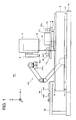
- Fig. 1 is a side elevation view of an inkjet drawing apparatus relating to the first embodiment of the present invention
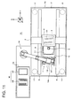
- Fig. 2 is its plan view.
- gantry 3 made of stone is provided along X-direction in the drawing on fixed platen 2, being rectangular planer view, made of stone. Said gantry 3 is shown by dashed lines in Fig. 1 .
- Z-stage 4 is provided which is vertically movable along the Z-direction in the drawing. Z-stage 4 is structured to be movable only vertically and unmovable in horizontal direction, and at the bottom end of Z-stage, head module 5 is provided
- Fig. 3 is a bottom view of head module 5 in which, a plurality of droplet jetting heads (hereinafter referred as "head") 51, each of which is arranged with a plurality of nozzles 51a, are arranged and held in zigzag arrangement along the array direction of nozzles 51 a on base plate 50, thus structuring a line head having long length in X-direction in the drawing.
- head droplet jetting heads
- cross-shaped position continuing markers 52 are formed at four appropriate corner positions. Wherein, markers 52 are arranged such that a line connecting two markers 52 separately formed along the X -direction is parallel to the nozzle row direction of each head 51.
- Head module 5 is arranged such that the nozzle surface of each head 51 faces downward, and can be place to be parallel to the surface of a recording member (not illustrated) arranged under each head 51. Head module 5 is installed at the bottom end of Z-stage 4 via a ⁇ rotation mechanism (not illustrated) for rotating head module 5 in ⁇ direction about an axis along the Z-direction.
- first camera 6 is provided as one body for visually confirming downward positions from the Z-stage.
- First camera 6 is a maintenance unit conforming camera configured with CCD and the like for confirming the position and posture of maintenance unit M (to be described later) being arranged downward, in the present embodiment.
- First camera 6 is installed as vertically movable independently with respect to Z-stage 4 by facing lens surface 6a downward. This vertical movement of first camera 6 is conducted to confirm the markers formed at the prescribed positions in cases of image confirmation of the position of maintenance unit M.
- transfer stage 7 for transporting the recording material
- ⁇ rotation mechanism 8 for rotating the transfer stage 7 in ⁇ direction about an axis along the Z-direction
- Y-movement mechanism 9 for linearly moves both transfer stage 7 and ⁇ rotation mechanism 8 along the Y-direction in the drawing
- X-movement mechanism 10 for linearly moves both transfer stage 7 and ⁇ rotation mechanism 8 along the X-direction in the drawing.
- X-direction and Y-direction are mutually perpendicular in the horizontal plane parallel to the upper surface of fixed platen 2, where the X direction indicates a sub-scanning direction and Y-direction indicates a main-scanning direction.
- Z-direction is perpendicular to the upper surface of fixed platen 2, and orthogonal to both the X-direction and Y-direction.
- Transfer stage 7 is a rectangular flat plate in the planer view, and on the upper surface of transfer stage 7, provided in one body are drawing table 11, and second camera 12 in the vicinity of the drawing table 11, for visually observing upward.
- drawing table 11 is made parallel to the upper surface of fixed platen 2, and a recording material (not illustrated), which is an object to execute a prescribed drawing by receiving the droplets ejected from head module 5, is placed and held on the upper surface.
- This drawing table 11 is formed to protrude upward from the surface of transfer stage 7. Rotation center of ⁇ rotation mechanism 8 is set at the central position of drawing table 11.
- Second camera 12 is a head position confirming camera configured with CCD and the like for confirming the position and posture of head module 5 arranged upside, in the present embodiment. Second camera 12 is installed by being laid at a prescribed position on the upper surface of transfer stage 7, in an unmovable position with respect to transfer stage 7.
- transfer stage 7 protrudes laterally along the Y-direction in the drawing than the installation space of drawing table 11 and second camera 12.
- Maintenance unit installation section 13 for installing a maintenance unit is formed on the upper surface space of the protruded portion. Maintenance unit installation section has minimal sufficient space for installing any of one of the plurality of kinds of maintenance units M. Due to this, although enabling the maintenance by the plural kinds of maintenance unit M, transfer stage 7 remains from being unnecessary enlarged size, and further, the moving distance for moving the maintenance unit M to be installed on this section to just under the head module 5 can be kept in minimum.
- drawing table 11 is formed to be higher than the surface of transfer stage 7, a large height difference is generated between drawing table 11 and the upper surface of the maintenance unit installation section 13.
- this height difference approximately the same as the maximum height of maintenance unit M to be installed on maintenance unit installation section 13, a space capable of inserting maintenance unit M can be ensured between head module 5 and maintenance unit installation section 13 at the time of maintenance operation, and the vertical moving distance for movement of head module 5 can remain short.
- holding mechanism 13a is provided for holding the installed maintenance unit M to be unmovable during maintenance.
- holding mechanism 13a is not required, but a lock mechanism to mechanically hold maintenance unit M to be unmovable, a suction mechanism to suck the maintenance unit M to be unmovable by air suction or magnetic force, and the like can be applied.
- Transfer stage 7 is configured to be movable in a prescribed region including just under the portion of head module 5 installed on Z-stage 4 in horizontal direction (X, Y, and ⁇ directions), by rotation movement in ⁇ direction by ⁇ rotation mechanism 8, and by movement along X-movement mechanism 10 and Y-movement mechanism 9. Therefore, maintenance unit M installed at maintenance unit installation section 13 on this transfer stage 7 can be transported to be just under head module 5 by the horizontal movement of transfer stage 7.
- the maintenance unit transfer means of the present invention is configured of this transfer stage 7.
- Each positions transfer stage 7 in X-direcdon, Y-direction and ⁇ -direction is configured to be detected with high accuracy by unillustrated encoders.
- maintenance unit installation mechanism 14 for installing maintenance unit M at maintenance unit installation section on transfer stage.
- maintenance unit installation mechanism 14 is configured of a multiple-jointed robot arm, which is separately structured from fixed platen 2 without being installed on fixed platen 2, and is installed on maintenance unit arrangement table 15 provided at the side of fixed platen.
- maintenance unit arrangement table 15 On maintenance unit arrangement table 15, plural kinds of maintenance unit M (m 1, m2, m3) are arranged to be capable of selective usage.
- Maintenance unit installation mechanism 14 has hand unit 14a at its front end, and is configured to select and hold any one of maintenance unit M (m1, m2, or m3) from plural kinds of maintenance unit M (m1, m2, and m3), to transport to the proper position of maintenance unit installation section 13 on transfer stage 7 by driving of each joint, and to install on said maintenance unit installation section 13. Therefore, the maintenance unit selection arranging means of the present invention is configured of this maintenance unit installation mechanism.
- fixed platen 2 is mounted via vibration-free mechanism 17 such as an air suspension system on apparatus base table 16.
- maintenance unit installation mechanism 14 and maintenance unit arrangement table 15 may be provided on apparatus base table 16, as shown in the figure, they may be provided on a separate body, such as on the floor.
- vibration-free mechanism 17 since maintenance unit installation mechanism 14 is not installed on fixed platen 2, vibration generated in accordance with its drive can be prevented from directly being transferred to fixed platen 2. Therefore, even if maintenance unit installation mechanism 14 is provided on apparatus base table 16, any vibration generated in accordance with its drive is suppressed to be directly transferred to fixed platen 2, and is sufficiently reduced by vibration-free mechanism 17, which can reduce the influence on installation condition of each head 51 of bead module 5. Further, since fixed platen 2 does not require the installation space of maintenance unit installation mechanism 14, expensive fixed platen 2 can be downsized to requisite minimum, which enables to reduce costs.
- Fig. 4 is a block diagram showing schematically the internal configurations of inkjet drawing apparatus 1A.
- Designation 100 shows a computing section (CPU) to control the total system, and controls each of stage controller 101, arm controller 102, image processing section 103, and ejection control section 104.
- CPU computing section
- Stage controller 101 controls the drive of stage driver 105 and 106 based on control signals from computing section 100, and respectively drives ⁇ axis motor 110 for rotating head module 5 installed on Z-stage 4 in the ⁇ direction, and Z axis motor 111 for vertical movement of Z-stage 4 in the Z-direction.
- stage controller 101 controls the drive of stage drivers 107 - 109 to respectively drive X-axis motor 112 to move transfer stage 7 in the X direction, Y-axis motor 113 to move in Y-direction, and ⁇ -axis motor 114 to rotate in the ⁇ -direction.
- arm controller 102 Based on control signals from computing section 100, arm controller 102 drives the robot arm as maintenance unit installation mechanism 14 to control various movements.
- image processing section 103 controls the drive of camera controller 115 to execute image capturing operations of the first camera installed on Z-stage 4, and the second camera installed on transfer stage 7, and to execute processing of captured image.
- section control section 104 controls the drive of each head 51 in head module 5 to execute ink jetting process based on prescribed drawing data
- various kinds of maintenance unit M will be described.
- Fig. 5 shows the plan view of wiping unit m1, which is provided with wiping member 201 arranged on planar view rectangle base plate 200 in two rows corresponding to two rows of heads arranged on head module 5.
- Each wiping member 201 is formes to be a shape of long length tape having a width approximately the same as that of the nozzle surface of head 51, is rolled around roller 202, and is arranged in parallel at an edge portion on base plate 200, with the interval same as the row interval of head 51.
- Leading edge of wiping member 201 is capable ofbeing taken up by take-up roller 203 arranged at the other end of bass plate 200.
- Designation 203 is a motor to rotate take-up roller 203.
- two pairs of holding rollers 205 are respectively provided to cause a prescribed tensile force on wiping member 201 between them.
- the interval distance between the two pairs of holding rollers 205 is made a little greater than the width in sub-scanning direction of all heads 51 arranged on head module 5.
- the surface of wiping member 201 nipped by the two pairs of holding rollers 205 configures a wiping surface for wiping the nozzle surface of each head 51 on head module 5.
- wiper head 206 corresponding to each head is provided, to support the back surface of wiping member 201 to enhance the wiping effect by contacting the wiping surface to the nozzle surface of each head 51.
- cross-shaped positioning markers 207 are formed.
- Wiping unit m1 is placed and positioned at maintenance unit installation section 13 on transfer stage 7, and each wiping member 201 and head 51 are brought into contact, after that, by driving motor 204 to take up the wiping member 201 around take-up roller axis 203, the wiping surface wipes each nozzle 51 for cleaning the nozzle surface.
- Power source to drive each motor 204 may be supplied from a power cord connected to a power connector (not illustrated), or may be supplied by providing electrode 13b for power supply on maintenance unit installation section 13 as shown in Fig. 2 , and in cases where wiping unit m1 is installed, connecting the electrode 13b to an electrode (not illustrated) provided on the wiping unit ml.
- Fig. 6 shows the plan view of sucking unit m2, which is provided with sucking cap 301 arranged on planar view rectangle base plate 300 corresponding to the number and arrangement of each head 51 on head module 5.
- sucking cap 301 To each sucking cap 301, one end of sucking pile 302 is connected.
- the other end of sucking pipe 302 is connected to a suction pump (not illustrated), and air in each sucking cap 301 is sucked by the drive of suction pump.
- cross-shaped positioning markers 303 are formed.
- Sucking unit m2 is placed and positioned at maintenance unit installation section 13 on transfer stage 7, and each sucking cap 301 and each head 51 are made to be in close contact, after that, by driving the suction pump to make a negative pressure state in each sucking cap 301, and forcibly sucking ink from nozzle 51a of each head 51, clearance of ink clogging and ejection of air bubble are performed. Further, after making the close contact of each sucking cap 301 and each head 51, by keeping not to drive the suction pump, it may function to prevent the drying up in nozzle 51a
- Fig. 7 shows the plan view of flushing tray m3, which is provided with tray 401 with the size capable of enclosing all heads 51 of head module 5, on planar view rectangle base plate 400.
- cross-shaped positioning markers 402 are formed.
- Flushing tray m3 is placed and positioned on maintenance unit installation section 13 on transfer stage 7, and after being arranged under head module 5 receives droplets forcibly ejected from each nozzle 51a into tray 401, for clearance of nozzle clogging and for homogenization of each nozzle 51a.
- maintenance unit M (m1, m2, and m3) are arranged on maintenance unit arrangement table 15. Since positions for those units are not strictly specified, after grabbing a desired maintenance unit M (mi, m2, or m3) by driving the arm, maintenance unit installation mechanism 14 needs to precisely position it toward each head 51 of head module 5.
- the maintenance operation reads out maintenance device basic data regarding wiping unit m1 for executing the wiping (S2), drives maintenance unit installation mechanism 14 based on position data in the maintenance device basic data, grabs and holds wiping unit m1 out of the plurality of kinds of maintenance unit M (m1, m2, m3) with fore hand unit 14a, conveys it onto transfer stage 7, and installs it on maintenance unit installation section 13.
- maintenance unit M is installed in a state of having been fixed in position to a certain extent with respect to head module 5 (S3, Fig. 11 ). After said installation, wiping unit m1 is held securely on maintenance unit installation section 13 by holding mechanism 13a.
- transfer stage 7 has moved to and stopped at a prescribed position (installation waiting position) such that maintenance unit installation section 13 evacuates sufficiently from the position under Z-stage 4.
- the installation waiting position is previously determined and its positional coordinates are included in the maintenance device basic data read out in the step S2.
- the first camera 6 attached to Z-stage 4 confirms of any positioning marker 207 on wiping unit m1 through image confirmation (S4, Fig. 12 ). This confirmation operation is repeated for times of the number of positioning marker 207, to obtain positional coordinate of each marker. After obtaining the positional coordinates of each positioning marker 207, the posture of wiping unit m 1 is calculated from each positional coordinate.
- Fig.9 shows a flow ofposture calculation. Firstly obtaining each positional coordinate (X, Y) of four points of positioning marker 207, and memorizes them as marker data 1 to 4 (S20).
- the posture data of wiping unit m1 is memorized as the present posture data ( ⁇ rn, Mrave) of wiping unit m1 on maintenance unit installation section 13 (S5).
- Either one series of above two series of processes S3 - S5 and processes S6 - S8 may be executed before the other series. Further as the first process ofmaintenance operation, the above series of steps S6 - 8 may be executed first to previously obtain posture data of head module 5.
- wiping unit m1 since wiping unit m1 has been transported and simply placed onto maintenance unit installation section 13, accurate positioning to each head 51 of head module 5 is not executed Therefore in order to wipe each head 51 with wiping unit m1, the postures of both units are required to be adjusted to coincide. In order to adjust both postures, although head module 5 and wiping unit m1 may be relatively moved, only wiping unit m1 is moved in the X, Y, and ⁇ directions to make the posture of wiping unit m1 coincide with the posture of head module 5.
- Fig. 10 shows a flow for calculating the correction adjusting amount for moving wiping unit m1.
- Firstly called out are the memorized data of posture data ( ⁇ m, Mrave) of wiping unit m1, posture data ( ⁇ b, Hrave) of head module 5, and maintenance device basic data Dm (S30).
- Maintenance device basic data Dm includes information of contact position relationship between head module 5 and wiping unit m1.
- transfer stage 7 is moved in X, Y, and ⁇ directions to finely adjust the position of wiping unit m1 (S10).
- the posture of wiping unit m1 on transfer stage 7 is made to coincide with the posture of head module 5 ( Fig. 14 ).
- inkjet drawing apparatus 1A relating to the present invention, since only one kind of maintenance unit among the plural kinds of maintenance unit M (m 1, m2, m3) is required to be installed on transfer stage 7, transfer stage 7 needs not be made long and large sized. Further, since the mechanism for installing maintenance unit M onto transfer stage (maintenance unit installation mechanism 14) is not provided on the same fixed platen 2 as transfer stage 7, a positional shift of head 51 due to the vibration caused by the installation operation of maintenance unit M is suppressed and highly accurate maintenance is made possible.
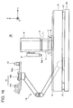
- Fig. 16 is a side elevation view of an inkjet drawing apparatus relating to the second embodiment of the present invention
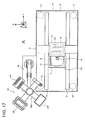
- Fig. 17 is its plan view. Since the part given the same designation as that of inkjet drawing apparatus 1A is the identical component part, its detailed explanation will be omitted.
- This maintenance unit transfer mechanism 18 is configured with a multiple-jointed robot similarly to maintenance unit installation mechanism 14 of the first embodiment, and arranged at the side of fixed platen 2 without being provided on fixed platen 2. Therefore, any vibration caused by its movement does not affect head module 5 on fixed platen 2, and the installation space of maintenance unit transfer mechanism 18 is not required on fixed platen 2.
- maintenance unit installation mechanism 14 may be installed on apparatus base table 16 at the side of fixed platen 2.
- Rotation table 18a On which all of the plural kinds of maintenance unit M (m1, m2, and m3) are arranged, is provided.
- Rotation table 18a is rotatable a horizontal ⁇ direction at the forefront oaf the arm, and at predetermined prescribed positions on its upper surface, respectively arranged and fixed are the plural kinds of maintenance unit M (m1, m2, and m3) and second camera 12 for image confirming the position of head module 5 upward from the bottom surface side.
- rotation table 18a By driving each joints of maintenance unit transfer mechanism 18, rotation table 18a is movable in the horizontal and vertical directions within a prescribed region including the portion just under head module 5. Further, by rotating the rotation table 18a, one kind of unit among the plural kinds of maintenance unit M (m1, m2, and m3) can be executed positioning to just under head module 5, and after the positioning, the unit can be made contact with each head 51 by raising the arm Therefore, in the present embodiment this maintenance unit transfer mechanism 18 configures the maintenance unit transfers means of the present invention.
- Positional information accompanied by each moving operation of maintenance unit transfer mechanism 18 is respectively detected accurately by an encoder (not illustrated).
- inkjet drawing apparatus 1B of the second embodiment by selecting arbitrary one kind of maintenance unit M among the plural kinds of maintenance unit M (m1, m2, and m3) and rotating rotation table 18a, the selected maintenance unit M is positioned to coincide with the posture of head module 5 at the bottom of head module 5.
- this positioning operation can be executed according to Fig. 8 - Fig. 10 , however, since second camera 12 is installed on rotation table 18a in the present embodiment, by inserting second camera 12 to the under part of head module 5 from where drawing table 11 has evacuated, the position of head module 5 is confirmed ( Fig. 18 ). At this time, Z-stage 4 moves upward to form an enough insertion space under it.
- rotation table 18a rotates and transports flushing tray m3 toward the portion under first camera 6, and positional confirmation is executed by said first camera 6 ( Fig. 19 ).
- first camera 6 comes down for image confirming of positioning marker 402 on flushing tray m3.
- rotation table 18a is rotated such that flushing tray m3 coincides with the posture of head module 5 to make flushing tray m3 positioned under the head module 5 ( Fig. 20 ).
- transfer stage 7 provided with drawing table 11 is made movable by Y-movement mechanism 9 in Y-direction on fixed platen 2 up to a position (maintenance position) where said drawing table 11 is sufficiently evacuated from the position under head module 5.
- rotation table provided with maintenance unit M (m1, m2, and m3) and second camera 12 can be inserted, is ensured under head module 5. Since drawing table 11 is formed high to protrude from the surface of transfer stage 7, the moving distance for lifting up head module 5 to insert rotation table 18a into the position under head module 5 can be made short.
- the arrangement table for arranging plural kinds of maintenance unit M (m1, m2, and m3) is not required to be separately provided, which enables to make the total apparatus installation space compact
- Maintenance unit installation mechanism 14 which is an example of maintenance unit selecting/arranging means explained in the first embodiment, may be configured as below alternatively to the configuration of multiple-jointed robot arm.
- Fig. 21 is a side elevation view of an inlet drawing apparatus provided with the other embodiment of maintenance unit selection/placing means, and Fig. 22 is its plan view. Since the part given a same designation as that of Fig. 1 or Fig. 2 is the identical component part, its detailed explanation will be omitted.
- gantry 20 is provided along X-direction in the drawing so as to step over transfer stage 7 and fixed platen 2. Therefore, in this case gantry 20 is not installed on fixed platen 20, but installed on apparatus base table 16.
- maintenance unit installation mechanism 19 for installing maintenance unit M onto maintenance unit installation section 13 on transfer stage 7 is provided to be capable of slide movement in X-direction in the drawing and also vertical movement in Z-direction.
- maintenance unit arrangement table 21 is provided on apparatus base table 16, and on its upper surface, the plural kinds of maintenance unit M (m1, m2, and m3) are arranged, so as to be selectively usable, along X-direction similarly to gantry 20.
- This maintenance unit installation mechanism 19 has, on its bottom end, hand unit 19a to grab and hold the maintenance unit M, and is configured to selectively grab and hold any one of maintenance unit among the plural kinds of maintenance unit M (m1, m2, and m3) by hand unit 19a, and to allow slide movement along gantry 20 to install on maintenance unit installation section 13 on transfer stage 7 which has moved to the position (installation waiting position) under gantry 20.
- the maintenance unit selecting arranging means of the present invention is configured with this maintenance unit installation mechanism 19 provided on gantry 20.
Landscapes
- Coating Apparatus (AREA)
- Ink Jet (AREA)
Abstract
Description
- The present invention relates to an inkjet drawing apparatus, and specifically relates to an inkjet drawing apparatus that enables highly accurate maintenance without requiring increase of the length and dimensions of a stage on the apparatus base table.
- In recent years fine processing technologies utilizing inkjet technologies have attracts rising attention. For example, in the manufacturing field of a color filter to be used for a liquid crystal display panel, a wiring pattern of semiconductor and the like, requirements are increasing to land the various types of liquid droplets ejected from a droplet jetting head (hereinafter referred as a head) at a fine target on a work (recorded member) with errors of approximately 1 µm.
- In order to control the landing position with a high degree of accuracy, the head position is preferably arranged at a equally high accurate position. Further, maintenance work to ensure the appropriate landing position of the liquid droplet is necessary.
- Conventionally, to conduct maintenance.
Patent Document 1 discloses an apparatus where a maintenance area is provided in the apparatus main body adjacent to a drawing area, and at the time of maintenance, a carriage holding a head is moved to the maintenance area. - Further,
Patent Document 2 discloses to make the head unmovable on the apparatus base table, and provide a plurality of types of maintenance units on the same apparatus base table to be horizontally movable within a prescribed region including a portion just under the head, and at the time of maintenance to move a required maintenance unit to a position just under the head. -
- Patent Document 1: Unexamined Japanese Patent Application Publication No.
2005-254,800 - Patent Document 2: Unexamined Japanese Patent Application Publication No.
2008-155,113 - According to the technology disclosed in
Patent Document 1, since it is necessary to move a carriage holding the head to the maintenance area at the time of maintenance, backlash is caused by the movement of the carriage to generate fine misalignments at the position of head arrangement, which may cause a shift of droplet landing position. Since inkjet drawing apparatuses require extremely high landing position accuracy in µm order, quite a small head positional shift may become very critical. - For this reason, the configuration as described in
Patent Document 2 is preferable, where the head is arranges to be unmovable and the maintenance units are moved to the position just under the head. - However in the case of arranging the head to be unmovable, in addition to the installation area and moving area of the drawing table to hold the work, namely the object being drawn, areas for installation and movement of the maintenance units are required. The maintenance units generally include a capping unit to prevent the nozzle surface of head from drying, a sucking unit to forcibly suck the ink from the nozzle, a flushing tray to pick up the forcibly ejected ink from the nozzle, a wiping unit to wipe the blots such as the residual ink attached on the nozzle surface, and the likes. These plural kinds of maintenance units are required to be installed on a stage to be usable. Therefore, these installation areas are necessary to be secured on the stage, which causes the problem of increasing the length and the dimensions of the stage.
- Further, since both the drawing table and the maintenance units need to be positioned in high accuracy with respect to the head, the movement of these units also needs to be conducted with high accuracy. Since the movement of these units are required of high accuracy, in addition to the problem of extremely high cost of the stage for executing such high accuracy movement, a problem of generating small positional shifts of the head may be caused, since the stage is required to move a relatively long distance for using the prescribed maintenance unit and vibration accompanied by the movement transfers from the apparatus base table to the head.
- Therefore, an object of the present invention is to provide an inkjet drawing apparatus that enables to execute highly accurate maintenance by positioning the maintenance units at the head, and suppress the generation of head positions shift due to vibration, without requiring an increase of the length and the dimensions of the stage.
- Other objects of the present invention will be disclosed in the description below.
- The above object will be solved by each invention described below.
- The invention described in
Claim 1 is: - 1. An inkjet drawing apparatus including a head module which holds a droplet jetting head provided with a nozzle for ejecting droplets, and is configured to be unmovable in a horizontal direction; and a drawing table which supports a recording member on whose upper surface, and is configured to be movable in the horizontal direction; where the inkjet drawing apparatus executes a prescribed drawing by ejecting the droplets onto the recording member from the droplet jetting head, characterising in having:
- a maintenance unit transfer means which is configured to be movable within a prescribed region including a position just under the head module, and which transfers a maintenance unit for conducting a maintenance of the droplet jetting head toward the position just under the head module, and executes positioning of the maintenance unit with respect to the droplet jetting head; and
- a maintenance unit selecting/arranging means which selects any one of a plurality of kinds of maintenance units for conducting the maintenance of the droplet jetting head, and places the selected maintenance unit on the maintenance unit transfer means.
- 2. The inkjet drawing apparatus described in
claim 1, further including a relative position measuring means which measures a relative position between the head module and the maintenance unit being transferred by the maintenance unit transfer means, wherein the maintenance unit transfer means executes a fine adjustment of position of the maintenance unit based on a value measured by the relative position measuring means. - The invention described in
Claim 3 is: - 3. The inkjet drawing apparatus described in
claim - The invention described in
claim 4 is: - 4. The inkjet drawing apparatus described in
claim - The invention described in
claim 5 is: - 5. The inkjet drawing apparatus described in any one of
claims 1 to 4, further including a maintenance unit arranging table, on whose upper surface the plurality of kinds of maintenance units are arranged. - The invention described in
Claim 6 is: - 6. The inkjet drawing apparatus described in any one of
claims 1 to 5, wherein the head module and the drawing table are arranged on a common fixed platen, and the maintenance unit selecting/arranging means is not arranged on the common fixed platen. - The invention described in
Claim 7 is: - 7. The inkjet drawing apparatus described in any one of claims I to 6, wherein the drawing table and the maintenance unit transfer means are provided on a common stage which is movable in the horizontal direction within the prescribed region including the position just under the head module, and rotatable about an axis perpendicular to the upper surface of the drawing table.
- The invention described in
Claim 8 is: - 8. The inkjet drawing apparatus described in any one of
claims 1 to 7, wherein the drawing table is configured to move to a position where the drawing table does not interfere with the maintenance unit at the time of maintenance by the maintenance unit, and ensures a space to insert the maintenance unit under the head module. - The invention described in
Claim 9 is: - 9. An inkjet drawing apparatus including a head module which holds a droplet jetting head provided with a nozzle for ejecting droplets, and is configured to be unmovable in a horizontal direction; and a drawing table which supports a recording member on whose upper surface, and is configured to be movable in the horizontal direction, where the inkjet drawing apparatus executes a prescribed drawing by ejecting the droplets onto the recording member from the droplet jetting head, characterizing in having:
- a maintenance unit transfer means which is configured to be movable within a prescribed region including a position just under the head module, transfers a maintenance unit for conducting a maintenance of the droplet jetting head toward the position just under the head module, and executes positioning of the maintenance unit with respect to the droplet jetting head,
- wherein the maintenance unit is provided at an end of the maintenance unit transfer means configured with a robot arm which is movable in horizontal and vertical directions within the prescribed region including the position just under the head module,
- The invention described in
Claim 10 is: - 10. The inkjet drawing apparatus described in
claim 9, further including a relative position measuring means which measures a relative position between the head module and the maintenance unit being transferred by the maintenance unit transfer means, wherein the maintenance unit transfer means executes a fine adjustment of the position of maintenance unit based on a value measured by the relative position measuring means. - The invention described in
Claim 11 is: - 11. The inkjet drawing apparatus described in
claim - The invention describe in
Claim 12 is: - 12. The inkjet drawing apparatus described in any one of
claims 9 to 11, wherein the head module and the drawing table are arranged on a common fixed platen, and the maintenance unit transfer means is not arranged on the common fixed platen. - The invention described in
Claim 13 is: - 13. The inkjet drawing apparatus described in any one of
claims 9 to 12, wherein the drawing table is configured to move to a position where the drawing table does not interfere with the maintenance unit at the time of maintenance by the maintenance unit, and ensures a space to insert the maintenance unit under the head module. - According to the present invention, an inkjet drawing apparatus can be provided which can suppress positional shifts of a head due to vibration without requiring an increase of length and dimensions of a stage, and highly accurate maintenance is made possible by positioning a maintenance unit to the head.
-
-
Fig.1 is a side elevation view of an inkjet drawing apparatus relating to the first embodiment; -
Fig. 2 is a plan view of an inkjet drawing apparatus relating to the first embodiment; -
Fig. 3 is a bottom view of a head module; -
Fig. 4 is a block diagram showing schematically the internal configuration of the inkjet drawing apparatus; -
Fig. 5 is a plan view of a wiping unit; -
Fig. 6 is a plan view of a sucking unit -
Fig. 7 is a plan view of a flushing tray, -
Fig. 8 is a flow chart describing maintenance operations in the inkjet drawing apparatus relating the first embodiment; -
Fig. 9 is a flow chart describing maintenance operations in the inkjet drawing apparatus relating the first embodiment -
Fig. 10 is a flow chart describing maintenance operations in the inkjet drawing apparatus relating the first embodiment; -
Fig. 11 is a plan view showing maintenance operations in the inkjet drawing apparatus relating the first embodiment; -
Fig. 12 is a plan view showing maintenance operations in the inkjet drawing apparatus relating the first embodiment; -
Fig. 13 is a plan view showing maintenance operations in the inkjet drawing apparatus relating the first embodiment; -
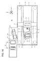
Fig. 14 is a plan view showing maintenance operations in the inkjet drawing apparatus relating the first embodiment; -
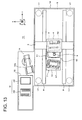
Fig. 15 is a plan view showing maintenance operations in the inkjet drawing apparatus relating the first embodiment; -
Fig. 16 is a side elevation view of an inkjet drawing apparatus relating to the second embodiment; -
Fig.17 is a plan view of an inkjet drawing apparatus relating to the second embodiment; -
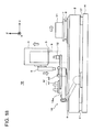
Fig. 18 is a plan view showing maintenance operations in the inkjet drawing apparatus relating the first embodiment; -
Fig. 19 is a plan view showing maintenance operations in the inkjet drawing apparatus relating the second embodiment; -
Fig. 20 is a plan view showing maintenance operations in the inkjet drawing apparatus relating the second embodiment; -
Fig. 21 is a side elevation view of an inkjet drawing apparatus provided with another embodiment of maintenance unit selecting/arranging means; and -
Fig. 22 is a plan view of an inkjet drawing apparatus provided with the other embodiment of maintenance unit selecting/arranging means. - Hereinafter, embodiments of the present invention will be described in detail referring to the drawing.
-
Fig. 1 is a side elevation view of an inkjet drawing apparatus relating to the first embodiment of the present invention, andFig. 2 is its plan view. - In
inkjet drawing apparatus 1A,gantry 3 made of stone is provided along X-direction in the drawing on fixedplaten 2, being rectangular planer view, made of stone.Said gantry 3 is shown by dashed lines inFig. 1 . Ongantry 3, Z-stage 4 is provided which is vertically movable along the Z-direction in the drawing. Z-stage 4 is structured to be movable only vertically and unmovable in horizontal direction, and at the bottom end of Z-stage,head module 5 is provided -
Fig. 3 is a bottom view ofhead module 5 in which, a plurality of droplet jetting heads (hereinafter referred as "head") 51, each of which is arranged with a plurality ofnozzles 51a, are arranged and held in zigzag arrangement along the array direction ofnozzles 51 a onbase plate 50, thus structuring a line head having long length in X-direction in the drawing. On the bottom surface ofbase plate 50, cross-shapedposition continuing markers 52 are formed at four appropriate corner positions. Wherein,markers 52 are arranged such that a line connecting twomarkers 52 separately formed along the X -direction is parallel to the nozzle row direction of eachhead 51.Head module 5 is arranged such that the nozzle surface of eachhead 51 faces downward, and can be place to be parallel to the surface of a recording member (not illustrated) arranged under eachhead 51.Head module 5 is installed at the bottom end of Z-stage 4 via a θ rotation mechanism (not illustrated) for rotatinghead module 5 in θ direction about an axis along the Z-direction. - Further, on the side surface of Z-
stage 4,first camera 6 is provided as one body for visually confirming downward positions from the Z-stage.First camera 6 is a maintenance unit conforming camera configured with CCD and the like for confirming the position and posture of maintenance unit M (to be described later) being arranged downward, in the present embodiment.First camera 6 is installed as vertically movable independently with respect to Z-stage 4 by facinglens surface 6a downward. This vertical movement offirst camera 6 is conducted to confirm the markers formed at the prescribed positions in cases of image confirmation of the position of maintenance unit M. - On
fixed platen 2, provided are:transfer stage 7 for transporting the recording material; θrotation mechanism 8 for rotating thetransfer stage 7 in θ direction about an axis along the Z-direction; Y-movement mechanism 9 for linearly moves bothtransfer stage 7 andθ rotation mechanism 8 along the Y-direction in the drawing; andX-movement mechanism 10 for linearly moves bothtransfer stage 7 andθ rotation mechanism 8 along the X-direction in the drawing. - Wherein, X-direction and Y-direction are mutually perpendicular in the horizontal plane parallel to the upper surface of fixed
platen 2, where the X direction indicates a sub-scanning direction and Y-direction indicates a main-scanning direction. Z-direction is perpendicular to the upper surface of fixedplaten 2, and orthogonal to both the X-direction and Y-direction. -
Transfer stage 7 is a rectangular flat plate in the planer view, and on the upper surface oftransfer stage 7, provided in one body are drawing table 11, andsecond camera 12 in the vicinity of the drawing table 11, for visually observing upward. - The upper surface of drawing table 11 is made parallel to the upper surface of fixed
platen 2, and a recording material (not illustrated), which is an object to execute a prescribed drawing by receiving the droplets ejected fromhead module 5, is placed and held on the upper surface. This drawing table 11 is formed to protrude upward from the surface oftransfer stage 7. Rotation center of θrotation mechanism 8 is set at the central position of drawing table 11. -
Second camera 12 is a head position confirming camera configured with CCD and the like for confirming the position and posture ofhead module 5 arranged upside, in the present embodiment.Second camera 12 is installed by being laid at a prescribed position on the upper surface oftransfer stage 7, in an unmovable position with respect to transferstage 7. - Further, upper surface of
transfer stage 7 protrudes laterally along the Y-direction in the drawing than the installation space of drawing table 11 andsecond camera 12. Maintenanceunit installation section 13 for installing a maintenance unit (to be described later) is formed on the upper surface space of the protruded portion. Maintenance unit installation section has minimal sufficient space for installing any of one of the plurality of kinds of maintenance units M. Due to this, although enabling the maintenance by the plural kinds of maintenance unit M,transfer stage 7 remains from being unnecessary enlarged size, and further, the moving distance for moving the maintenance unit M to be installed on this section to just under thehead module 5 can be kept in minimum. - Since drawing table 11 is formed to be higher than the surface of
transfer stage 7, a large height difference is generated between drawing table 11 and the upper surface of the maintenanceunit installation section 13. By making this height difference approximately the same as the maximum height of maintenance unit M to be installed on maintenanceunit installation section 13, a space capable of inserting maintenance unit M can be ensured betweenhead module 5 and maintenanceunit installation section 13 at the time of maintenance operation, and the vertical moving distance for movement ofhead module 5 can remain short. - On maintenance
unit installation section 13, holdingmechanism 13a is provided for holding the installed maintenance unit M to be unmovable during maintenance. Specifically structuredholding mechanism 13a is not required, but a lock mechanism to mechanically hold maintenance unit M to be unmovable, a suction mechanism to suck the maintenance unit M to be unmovable by air suction or magnetic force, and the like can be applied. -
Transfer stage 7 is configured to be movable in a prescribed region including just under the portion ofhead module 5 installed on Z-stage 4 in horizontal direction (X, Y, and θ directions), by rotation movement in θ direction by θrotation mechanism 8, and by movement alongX-movement mechanism 10 and Y-movement mechanism 9. Therefore, maintenance unit M installed at maintenanceunit installation section 13 on thistransfer stage 7 can be transported to be just underhead module 5 by the horizontal movement oftransfer stage 7. The maintenance unit transfer means of the present invention is configured of thistransfer stage 7. - Each positions transfer
stage 7 in X-direcdon, Y-direction and □-direction is configured to be detected with high accuracy by unillustrated encoders. - At the side of fixed
platen 2, is provided is maintenanceunit installation mechanism 14 for installing maintenance unit M at maintenance unit installation section on transfer stage. In this case maintenanceunit installation mechanism 14 is configured of a multiple-jointed robot arm, which is separately structured from fixedplaten 2 without being installed on fixedplaten 2, and is installed on maintenance unit arrangement table 15 provided at the side of fixed platen. On maintenance unit arrangement table 15, plural kinds of maintenance unit M (m 1, m2, m3) are arranged to be capable of selective usage. - Maintenance
unit installation mechanism 14 hashand unit 14a at its front end, and is configured to select and hold any one of maintenance unit M (m1, m2, or m3) from plural kinds of maintenance unit M (m1, m2, and m3), to transport to the proper position of maintenanceunit installation section 13 ontransfer stage 7 by driving of each joint, and to install on said maintenanceunit installation section 13. Therefore, the maintenance unit selection arranging means of the present invention is configured of this maintenance unit installation mechanism. - As shown in
Fig. 1 , fixedplaten 2 is mounted via vibration-free mechanism 17 such as an air suspension system on apparatus base table 16. Although, maintenanceunit installation mechanism 14 and maintenance unit arrangement table 15 may be provided on apparatus base table 16, as shown in the figure, they may be provided on a separate body, such as on the floor. According to the present embodiment, since maintenanceunit installation mechanism 14 is not installed on fixedplaten 2, vibration generated in accordance with its drive can be prevented from directly being transferred to fixedplaten 2. Therefore, even if maintenanceunit installation mechanism 14 is provided on apparatus base table 16, any vibration generated in accordance with its drive is suppressed to be directly transferred to fixedplaten 2, and is sufficiently reduced by vibration-free mechanism 17, which can reduce the influence on installation condition of eachhead 51 ofbead module 5. Further, since fixedplaten 2 does not require the installation space of maintenanceunit installation mechanism 14, expensive fixedplaten 2 can be downsized to requisite minimum, which enables to reduce costs. -
Fig. 4 is a block diagram showing schematically the internal configurations ofinkjet drawing apparatus 1A. -
Designation 100 shows a computing section (CPU) to control the total system, and controls each ofstage controller 101,arm controller 102,image processing section 103, andejection control section 104. -
Stage controller 101 controls the drive ofstage driver computing section 100, and respectively drives θaxis motor 110 for rotatinghead module 5 installed on Z-stage 4 in the θ direction, and Z axis motor 111 for vertical movement of Z-stage 4 in the Z-direction. - Based on control signals from
computing section 100,stage controller 101 controls the drive of stage drivers 107 - 109 to respectively driveX-axis motor 112 to movetransfer stage 7 in the X direction, Y-axis motor 113 to move in Y-direction, and θ-axis motor 114 to rotate in the θ-direction. - Based on control signals from
computing section 100,arm controller 102 drives the robot arm as maintenanceunit installation mechanism 14 to control various movements. - Based on control signals from
computing section 100,image processing section 103 controls the drive ofcamera controller 115 to execute image capturing operations of the first camera installed on Z-stage 4, and the second camera installed ontransfer stage 7, and to execute processing of captured image. - Based on control signals from
computing section 100,section control section 104 controls the drive of eachhead 51 inhead module 5 to execute ink jetting process based on prescribed drawing data Here, various kinds of maintenance unit M will be described. -
Fig. 5 shows the plan view of wiping unit m1, which is provided with wipingmember 201 arranged on planar viewrectangle base plate 200 in two rows corresponding to two rows of heads arranged onhead module 5. - Each wiping
member 201 is formes to be a shape of long length tape having a width approximately the same as that of the nozzle surface ofhead 51, is rolled aroundroller 202, and is arranged in parallel at an edge portion onbase plate 200, with the interval same as the row interval ofhead 51. Leading edge of wipingmember 201 is capable ofbeing taken up by take-uproller 203 arranged at the other end ofbass plate 200.Designation 203 is a motor to rotate take-uproller 203. - Between
roller 202 and take-uproller 203, two pairs of holdingrollers 205 are respectively provided to cause a prescribed tensile force on wipingmember 201 between them. The interval distance between the two pairs of holdingrollers 205 is made a little greater than the width in sub-scanning direction of allheads 51 arranged onhead module 5. The surface of wipingmember 201 nipped by the two pairs of holdingrollers 205 configures a wiping surface for wiping the nozzle surface of eachhead 51 onhead module 5. At the back side of the wiping surface,wiper head 206 corresponding to each head is provided, to support the back surface of wipingmember 201 to enhance the wiping effect by contacting the wiping surface to the nozzle surface of eachhead 51. - At proper positions in the four corners on upper surface of
base plate 200,cross-shaped positioning markers 207 are formed. - Wiping unit m1 is placed and positioned at maintenance
unit installation section 13 ontransfer stage 7, and each wipingmember 201 andhead 51 are brought into contact, after that, by drivingmotor 204 to take up the wipingmember 201 around take-uproller axis 203, the wiping surface wipes eachnozzle 51 for cleaning the nozzle surface. - Power source to drive each
motor 204 may be supplied from a power cord connected to a power connector (not illustrated), or may be supplied by providingelectrode 13b for power supply on maintenanceunit installation section 13 as shown inFig. 2 , and in cases where wiping unit m1 is installed, connecting theelectrode 13b to an electrode (not illustrated) provided on the wiping unit ml. -
Fig. 6 shows the plan view of sucking unit m2, which is provided with suckingcap 301 arranged on planar viewrectangle base plate 300 corresponding to the number and arrangement of eachhead 51 onhead module 5. To each suckingcap 301, one end of suckingpile 302 is connected. The other end of suckingpipe 302 is connected to a suction pump (not illustrated), and air in each suckingcap 301 is sucked by the drive of suction pump. - At the proper positions in four corners on upper surface of
base plate 300,cross-shaped positioning markers 303 are formed. - Sucking unit m2 is placed and positioned at maintenance
unit installation section 13 ontransfer stage 7, and each suckingcap 301 and eachhead 51 are made to be in close contact, after that, by driving the suction pump to make a negative pressure state in each suckingcap 301, and forcibly sucking ink fromnozzle 51a of eachhead 51, clearance of ink clogging and ejection of air bubble are performed. Further, after making the close contact of each suckingcap 301 and eachhead 51, by keeping not to drive the suction pump, it may function to prevent the drying up innozzle 51a -
Fig. 7 shows the plan view of flushing tray m3, which is provided withtray 401 with the size capable of enclosing allheads 51 ofhead module 5, on planar viewrectangle base plate 400. - At proper positions in the four corners on the upper surface of
base plate 400,cross-shaped positioning markers 402 are formed. - Flushing tray m3 is placed and positioned on maintenance
unit installation section 13 ontransfer stage 7, and after being arranged underhead module 5 receives droplets forcibly ejected from eachnozzle 51a intotray 401, for clearance of nozzle clogging and for homogenization of eachnozzle 51a. - These various kinds of maintenance unit M (m1, m2, and m3) are arranged on maintenance unit arrangement table 15. Since positions for those units are not strictly specified, after grabbing a desired maintenance unit M (mi, m2, or m3) by driving the arm, maintenance
unit installation mechanism 14 needs to precisely position it toward eachhead 51 ofhead module 5. - Next, maintenance operations of the
inkjet drawing apparatus 1A will be described by use of flow charts shown inFigs. 8 - 10 , and plan views ofFigs. 11 - 15 illustrating the operations ofinkjet drawing apparatus 1A. The maintenance operation described below is executed by the control ofcomputing section 100 based on a prescribed program previously stored in a prescribed area incomputing section 100 or in an unillustrated storage device. - When a predetermined maintenance time comes, maintenance content, predetermined or determined by an operator, is selected (S1). Here, among a plurality of kinds of maintenance operations, the wiping operation is assumed to be executed by use of wiping unit ml.
- Tn a case where wiping is selected in maintenance content selection, the maintenance operation reads out maintenance device basic data regarding wiping unit m1 for executing the wiping (S2), drives maintenance
unit installation mechanism 14 based on position data in the maintenance device basic data, grabs and holds wiping unit m1 out of the plurality of kinds of maintenance unit M (m1, m2, m3) withfore hand unit 14a, conveys it ontotransfer stage 7, and installs it on maintenanceunit installation section 13. At this time, maintenance unit M is installed in a state of having been fixed in position to a certain extent with respect to head module 5 (S3,Fig. 11 ). After said installation, wiping unit m1 is held securely on maintenanceunit installation section 13 by holdingmechanism 13a. - At this time,
transfer stage 7 has moved to and stopped at a prescribed position (installation waiting position) such that maintenanceunit installation section 13 evacuates sufficiently from the position under Z-stage 4. The installation waiting position is previously determined and its positional coordinates are included in the maintenance device basic data read out in the step S2. - After wiping unit m1 has been installed and seemed to maintenance
unit installation section 13, by movingtransfer stage 7 in the X, and Y directions, thefirst camera 6 attached to Z-stage 4 confirms of anypositioning marker 207 on wiping unit m1 through image confirmation (S4,Fig. 12 ). This confirmation operation is repeated for times of the number ofpositioning marker 207, to obtain positional coordinate of each marker. After obtaining the positional coordinates of eachpositioning marker 207, the posture of wipingunit m 1 is calculated from each positional coordinate. -
Fig.9 shows a flow ofposture calculation. Firstly obtaining each positional coordinate (X, Y) of four points ofpositioning marker 207, and memorizes them asmarker data 1 to 4 (S20). - Next, by assuming the positional coordinates of point P2, that minimize the value of |Xp1 - Xpn| (n = 2, 3, or 4) viewed from positional coordinates (Xp1, Yp1) of any one of positioning markers 207 (assumed to be P1), to be (Xp2, Yp2), other positional coordinates P3 and P4 are assumed respectively to be (Xp3, Yp3) and (Xp4, Yp4) (S21).
- By rotating the positional coordinates P1-P4 of the four
positioning markers 207 about the rotation center coordinates (Xθ, Yθ) positioned at the center of drawing table 11, obtaining the angle θp that minimizes the value of {(Xp1- Xp2)2 + (Xp3 - Xp4)2} and the angle θp is memorized (S22). - Next, with respect to the positional coordinates P1-P4 of the four points of positioning
markers 207, calculating the positional coordinates of four points after the rotation by angle θp (S23), and the average value Prave of positional coordinates Pr1-Pr4 of the four points is obtained and memorized (S24). - Returning to
Fig. 8 , the posture data of wiping unit m1, having been obtained by the above process, is memorized as the present posture data (θrn, Mrave) of wiping unit m1 on maintenance unit installation section 13 (S5). - On the other hand, by moving
transfer stage 7 in X and Y directions, moving thesecond camera 12 attached ontransfer stage 7 toward position under head module 5 (S6), any ofpositioning marker 52 formed on bottom surface of head module is confirmed through image confirmation by the second camera 12 (S7,Fig. 13 ). This confirmation operation is repeated for times of the number ofposition confirmation marker 52. The confirmed positional coordinates of eachposition confirmation markers 52 is assumed to be head marker data, and according to the flow ofFig. 9 similarly to the above description, posture data (θh, Hrave) is calculated and memorized (S8). - Either one series of above two series of processes S3 - S5 and processes S6 - S8 may be executed before the other series. Further as the first process ofmaintenance operation, the above series of steps S6 - 8 may be executed first to previously obtain posture data of
head module 5. - After completing both the above series of steps of S3- S5 and S6 - S8, the memorized posture data of wiping unit m1, and the posture data of
head module 5 are read out, and from these data the posture of contact forhead module 5 and wiping unit m1 (the posture where eachhead 51ofhead module 5 and each wipingmember 201 of wiping unit m1 contact properly with each other) is calculated (S9). - To be more specific, since wiping unit m1 has been transported and simply placed onto maintenance
unit installation section 13, accurate positioning to eachhead 51 ofhead module 5 is not executed Therefore in order to wipe eachhead 51 with wiping unit m1, the postures of both units are required to be adjusted to coincide. In order to adjust both postures, althoughhead module 5 and wiping unit m1 may be relatively moved, only wiping unit m1 is moved in the X, Y, and θ directions to make the posture of wiping unit m1 coincide with the posture ofhead module 5. -
Fig. 10 shows a flow for calculating the correction adjusting amount for moving wiping unit m1. Firstly called out are the memorized data of posture data (θm, Mrave) of wiping unit m1, posture data (θb, Hrave) ofhead module 5, and maintenance device basic data Dm (S30). Maintenance device basic data Dm includes information of contact position relationship betweenhead module 5 and wiping unit m1. - Next, based on these data, angle correction adjusting value θadj ( = θh- θm) for adjusting wiping unit m1 to the posture of
head module 5 is calculated, and the result is memorized (S31). - Further, based on the above posture data and maintenance device basic data Dm, XY correction adjusting value Aadj (Xadj, Yadj) (= Hrave - Mrave + Dm) for adjusting wiping unit m1 to the posture of
mead module 5 is calculated, and the result is memorized (S32). - Then, returning to
Fig. 8 , based on the correction adjusting amount data obtained by the above described S31 and S32,transfer stage 7 is moved in X, Y, and θ directions to finely adjust the position of wiping unit m1 (S10). By this means, the posture of wiping unit m1 ontransfer stage 7 is made to coincide with the posture of head module 5 (Fig. 14 ). - After that, by moving
transfer stage 7 such that wiping unit m1 comes to the position just underhead module 5, moving down Z-stage 4 such thathead module 5 contacts with wiping unit m1, and executes the head maintenance (S11,Fig. 15 ). - As described above, according to
inkjet drawing apparatus 1A relating to the present invention, since only one kind of maintenance unit among the plural kinds of maintenance unit M (m 1, m2, m3) is required to be installed ontransfer stage 7,transfer stage 7 needs not be made long and large sized. Further, since the mechanism for installing maintenance unit M onto transfer stage (maintenance unit installation mechanism 14) is not provided on the same fixedplaten 2 astransfer stage 7, a positional shift ofhead 51 due to the vibration caused by the installation operation of maintenance unit M is suppressed and highly accurate maintenance is made possible. -
Fig. 16 is a side elevation view of an inkjet drawing apparatus relating to the second embodiment of the present invention, andFig. 17 is its plan view. Since the part given the same designation as that ofinkjet drawing apparatus 1A is the identical component part, its detailed explanation will be omitted. - In this
inkjet drawing apparatus 1B ontransfer stage 7, not provided are the maintenance unit installation section and the second camera, both of which are provided in the first embodiment. Plural kinds of maintenance unit M are provided on maintenanceunit transfer mechanism 18 arranged at the side of fixedplaten 2. Therefore, only drawing table 11 is provided ontransfer stage 7. - This maintenance
unit transfer mechanism 18 is configured with a multiple-jointed robot similarly to maintenanceunit installation mechanism 14 of the first embodiment, and arranged at the side of fixedplaten 2 without being provided on fixedplaten 2. Therefore, any vibration caused by its movement does not affecthead module 5 on fixedplaten 2, and the installation space of maintenanceunit transfer mechanism 18 is not required on fixedplaten 2. Similarly to the first embodiment, maintenanceunit installation mechanism 14 may be installed on apparatus base table 16 at the side of fixedplaten 2. - At the forefront of maintenance
unit installation mechanism 14, rotation table 18a, on which all of the plural kinds of maintenance unit M (m1, m2, and m3) are arranged, is provided. Rotation table 18a is rotatable a horizontal θ direction at the forefront oaf the arm, and at predetermined prescribed positions on its upper surface, respectively arranged and fixed are the plural kinds of maintenance unit M (m1, m2, and m3) andsecond camera 12 for image confirming the position ofhead module 5 upward from the bottom surface side. - By driving each joints of maintenance
unit transfer mechanism 18, rotation table 18a is movable in the horizontal and vertical directions within a prescribed region including the portion just underhead module 5. Further, by rotating the rotation table 18a, one kind of unit among the plural kinds of maintenance unit M (m1, m2, and m3) can be executed positioning to just underhead module 5, and after the positioning, the unit can be made contact with eachhead 51 by raising the arm Therefore, in the present embodiment this maintenanceunit transfer mechanism 18 configures the maintenance unit transfers means of the present invention. - Positional information accompanied by each moving operation of maintenance
unit transfer mechanism 18 is respectively detected accurately by an encoder (not illustrated). - Similarly to the first embodiment, in
inkjet drawing apparatus 1B of the second embodiment, by selecting arbitrary one kind of maintenance unit M among the plural kinds of maintenance unit M (m1, m2, and m3) and rotating rotation table 18a, the selected maintenance unit M is positioned to coincide with the posture ofhead module 5 at the bottom ofhead module 5. - Also in the present embodiment, this positioning operation can be executed according to
Fig. 8 -Fig. 10 , however, sincesecond camera 12 is installed on rotation table 18a in the present embodiment, by insertingsecond camera 12 to the under part ofhead module 5 from where drawing table 11 has evacuated, the position ofhead module 5 is confirmed (Fig. 18 ). At this time, Z-stage 4 moves upward to form an enough insertion space under it. - After that, in cases where flushing try m3 is selected for example, rotation table 18a rotates and transports flushing tray m3 toward the portion under
first camera 6, and positional confirmation is executed by said first camera 6 (Fig. 19 ). At this time,first camera 6 comes down for image confirming ofpositioning marker 402 on flushing tray m3. After that, rotation table 18a is rotated such that flushing tray m3 coincides with the posture ofhead module 5 to make flushing tray m3 positioned under the head module 5 (Fig. 20 ). - In the present embodiment,
transfer stage 7 provided with drawing table 11 is made movable by Y-movement mechanism 9 in Y-direction on fixedplaten 2 up to a position (maintenance position) where said drawing table 11 is sufficiently evacuated from the position underhead module 5. Thus the space, where rotation table provided with maintenance unit M (m1, m2, and m3) andsecond camera 12 can be inserted, is ensured underhead module 5. Since drawing table 11 is formed high to protrude from the surface oftransfer stage 7, the moving distance for lifting uphead module 5 to insert rotation table 18a into the position underhead module 5 can be made short. - According to inkjet drawing apparatus relating to the second embodiment, similar effects to the first embodiment can be also attained in addition, the arrangement table for arranging plural kinds of maintenance unit M (m1, m2, and m3) is not required to be separately provided, which enables to make the total apparatus installation space compact
- Maintenance
unit installation mechanism 14, which is an example of maintenance unit selecting/arranging means explained in the first embodiment, may be configured as below alternatively to the configuration of multiple-jointed robot arm. -
Fig. 21 is a side elevation view of an inlet drawing apparatus provided with the other embodiment of maintenance unit selection/placing means, andFig. 22 is its plan view. Since the part given a same designation as that ofFig. 1 orFig. 2 is the identical component part, its detailed explanation will be omitted. - In this
inkjet drawing apparatus 1C, at an end side of fixedplaten 2 along Y-direction in the drawing,gantry 20 is provided along X-direction in the drawing so as to step overtransfer stage 7 and fixedplaten 2. Therefore, in this case gantry 20 is not installed on fixedplaten 20, but installed on apparatus base table 16. Ongantry 20, maintenanceunit installation mechanism 19 for installing maintenance unit M onto maintenanceunit installation section 13 ontransfer stage 7 is provided to be capable of slide movement in X-direction in the drawing and also vertical movement in Z-direction. - At the side of fixed
platen 2, maintenance unit arrangement table 21 is provided on apparatus base table 16, and on its upper surface, the plural kinds of maintenance unit M (m1, m2, and m3) are arranged, so as to be selectively usable, along X-direction similarly togantry 20. - This maintenance
unit installation mechanism 19 has, on its bottom end,hand unit 19a to grab and hold the maintenance unit M, and is configured to selectively grab and hold any one of maintenance unit among the plural kinds of maintenance unit M (m1, m2, and m3) byhand unit 19a, and to allow slide movement alonggantry 20 to install on maintenanceunit installation section 13 ontransfer stage 7 which has moved to the position (installation waiting position) undergantry 20. Thus, the maintenance unit selecting arranging means of the present invention is configured with this maintenanceunit installation mechanism 19 provided ongantry 20. - By this
inkjet drawing apparatus 1C, similar effects can be also attained to the first embodiment. -
- 1A, 1B, 1C:
- inkjet drawing apparatus
- 2:
- fixed platen
- 3:
- gantry
- 4:
- Z-stage
- 5:
- head module
- 51:
- head
- 51a:
- nozzle
- 52:
- position confirmation marker
- 6:
- first camera
- 6a
- lens surface
- 7:
- transfer stage
- 8:
- θ-rotation mechanism
- 9:
- Y-movement mechanism
- 10:
- X-movement mechanism
- 11:
- drawing table
- 12:
- second camera
- 12a:
- lens surface
- 13:
- maintenance unit installation section
- 13a:
- holding mechanism
- 13b:
- electrode
- 14,19:
- maintenance unit installation mechanism
- 14a,19a:
- hand unit
- 15,21:
- maintenance unit arrangement table
- 16:
- apparatus base table
- 17:
- vibration-free mechanism
- 18:
- maintenance unit transfer mechanism
- 18a:
- rotation table
- 20:
- gantry
- M:
- maintenance unit
- m1:
- wiping unit
- m2:
- sucking unit
- m3:
- flushing tray
Claims (13)
- An inkjet drawing apparatus comprising a head module which holds a droplet jetting head provided with a nozzle for ejecting droplets, and is configured to be unmovable in a horizontal direction; and a drawing table which supports a recording member on whose upper surface, and is configured to be movable in the horizontal direction; where the inkjet drawing apparatus executes a prescribed drawing by ejecting the droplets onto the recording member from the droplet jetting head, characterizing in comprising:a maintenance unit transfer means which is configured to be movable within a prescribed region including a position just under the head module, and which transfers a maintenance unit for conducting a maintenance of the droplet jetting head toward the position just under the head module, and executes positioning of the maintenance unit with respect to the droplet jetting head; anda maintenance unit selecting/arranging means which selects any one of a plurality of kinds of maintenance units for conducting the maintenance of the droplet jetting head, and places the selected maintenance unit on the maintenance unit transfer means.
- The inkjet drawing apparatus described in claim 1, further comprising a relative position measuring means which measures a relative position between the head module and the maintenance unit being transferred by the maintenance unit transfer means, wherein the maintenance unit transfer means executes a fine adjustment of a position of the maintenance unit based on a value measured by the relative position measuring means.
- The inkjet drawing apparatus described in claim 1 or 2, wherein the maintenance unit selecting/arranging means is configured with a robot arm capable of holding one maintenance unit at an end of the robot arm.
- The inkjet drawing apparatus described in claim 1 or 2, wherein the maintenance unit selecting/arranging means is configured to be capable of slide movement along a gantry which is provided to step over the maintenance unit transfer means, and also capable of up-and-down movement, and wherein the maintenance unit selecting/arranging means comprises a hand unit which can hold one maintenance unit at a lower end of the hand unit
- The inkjet drawing apparatus described in any one of claims 1 to 4, further comprising a maintenance unit arranging table, on whose upper surface the plurality of kinds of maintenance units are arranged.
- The inkjet drawing apparatus described in any one of claims 1 to 5, wherein the head module and the drawing table are arranged on a common fixed platen, and the maintenance unit selecting/arranging means is not arranged on the common fixed platen.
- The inkjet drawing apparatus described in any one of claims 1 to 6, wherein the drawing table and the maintenance unit transfer means are provided on a common stage which is movable in the horizontal direction within the prescribed region including the position just under the head module, and rotatable about an axis perpendicular to the upper surface of the drawing table.
- The inkjet drawing apparatus described in any one of claims 1 to 7, wherein the drawing table is configured to move to a position where the drawing table does not interfere with the maintenance unit at the time of maintenance by the maintenance unit, and ensures a space to insert the maintenance unit under the head module.
- An inkjet drawing apparatus comprising a head module which holds a droplet jetting head provided with a nozzle for ejecting droplets, and is configured to be unmovable in a horizontal direction; and a drawing table which supports a recording member on whose upper surface, and is configured to be movable in the horizontal direction, where the inkjet drawing apparatus executes a prescribed drawing by ejecting the droplets onto the recording member from the droplet jetting head, characterizing in comprising:a maintenance unit transfer means which is configured to be movable within a prescribed region including a position just under the head module, transfers a maintenance unit for conducting a maintenance of the droplet jetting head toward the position just under the head module, and executes positioning of the maintenance unit with respect to the droplet jetting head,wherein the maintenance unit is provided at an end of the maintenance unit transfer means configured with a robot arm which is movable in horizontal and vertical directions within the prescribed region including the position just under the head module.
- The inkjet drawing apparatus described in claim 9, further comprising a relative position measuring means which measures a relative position between the head module and the maintenance unit being transferred by the maintenance unit transfer means, wherein the maintenance unit transfer means executes a fine adjustment of the position of maintenance unit based on a value measured by the relative position measuring means.
- The inkjet drawing apparatus described in claim 9 or 10, wherein the maintenance unit transfer means comprises, on its end, a rotary table on which a plurality of kinds of maintenance units are arranged.
- The inkjet drawing apparatus described in any one of claims 9 to 11, wherein the head module and the drawing table are arranged on a common fixed platen, and the maintenance unit transfer means is not arranged on the common fixed platen.
- The inkjet drawing apparatus described in any one of claims 9 to 12, wherein the drawing table is configured to move to a position where the drawing table does not interfere with the maintenance unit at the time of maintenance by the maintenance unit, and ensures a space to insert the maintenance unit under the head module.
Applications Claiming Priority (2)
| Application Number | Priority Date | Filing Date | Title |
|---|---|---|---|
| JP2008322445 | 2008-12-18 | ||
| PCT/JP2009/070461 WO2010071041A1 (en) | 2008-12-18 | 2009-12-07 | Inkjet drawing apparatus |
Publications (2)
| Publication Number | Publication Date |
|---|---|
| EP2359941A1 true EP2359941A1 (en) | 2011-08-24 |
| EP2359941A4 EP2359941A4 (en) | 2016-10-26 |
Family
ID=42268712
Family Applications (1)
| Application Number | Title | Priority Date | Filing Date |
|---|---|---|---|
| EP09833345.3A Withdrawn EP2359941A4 (en) | 2008-12-18 | 2009-12-07 | Inkjet drawing apparatus |
Country Status (4)
| Country | Link |
|---|---|
| US (2) | US8419163B2 (en) |
| EP (1) | EP2359941A4 (en) |
| JP (2) | JP5561169B2 (en) |
| WO (1) | WO2010071041A1 (en) |
Cited By (2)
| Publication number | Priority date | Publication date | Assignee | Title |
|---|---|---|---|---|
| EP2559558A1 (en) * | 2011-08-16 | 2013-02-20 | Ricoh Company, Ltd. | Image forming apparatus having carriage mounting recording head for ejecting liquid droplets |
| CN107160861A (en) * | 2016-03-08 | 2017-09-15 | 精工爱普生株式会社 | liquid injection device |
Families Citing this family (8)
| Publication number | Priority date | Publication date | Assignee | Title |
|---|---|---|---|---|
| JP5586299B2 (en) * | 2010-03-31 | 2014-09-10 | 東レエンジニアリング株式会社 | Inkjet coating device |
| KR101289501B1 (en) * | 2011-02-08 | 2013-07-24 | 이구환 | Nozzle cleaning blade of zet valve for dispensing |
| JP6595306B2 (en) * | 2015-11-04 | 2019-10-23 | 株式会社Fuji | Printing apparatus and component mounting substrate manufacturing apparatus |
| US11400477B2 (en) * | 2018-01-30 | 2022-08-02 | Ford Motor Company | Reversible nozzle in ultrasonic atomizer for clog prevention |
| JP7328860B2 (en) * | 2019-09-30 | 2023-08-17 | セーレン株式会社 | Inkjet recording device |
| US11400718B2 (en) | 2020-03-12 | 2022-08-02 | Ricoh Company, Ltd. | Liquid discharge apparatus |
| JP7614900B2 (en) | 2021-03-23 | 2025-01-16 | 株式会社Screenホールディングス | Printing device and printing method |
| JP7831062B2 (en) * | 2022-03-25 | 2026-03-17 | セイコーエプソン株式会社 | Control method for liquid dispensing device, liquid dispensing device |
Family Cites Families (8)
| Publication number | Priority date | Publication date | Assignee | Title |
|---|---|---|---|---|
| JP2004130299A (en) * | 2002-08-02 | 2004-04-30 | Seiko Epson Corp | Droplet discharge device, method of manufacturing electro-optical device, electro-optical device, and electronic apparatus |
| JP4586485B2 (en) | 2004-02-13 | 2010-11-24 | セイコーエプソン株式会社 | Droplet ejection device, electro-optical device manufacturing method, electro-optical device, and electronic apparatus |
| JP4666946B2 (en) | 2004-04-28 | 2011-04-06 | キヤノン株式会社 | Discharge port surface cleaning method, liquid discharge apparatus, and probe carrier manufacturing apparatus |
| US7275802B2 (en) * | 2005-03-03 | 2007-10-02 | Hewlett-Packard Development Company, L.P. | Cleaner |
| KR100782816B1 (en) * | 2005-08-19 | 2007-12-06 | 삼성전자주식회사 | Inkjet image forming apparatus and nozzle unit maintenance method |
| US20080024532A1 (en) * | 2006-07-26 | 2008-01-31 | Si-Kyoung Kim | Methods and apparatus for inkjet printing system maintenance |
| JP2008155113A (en) | 2006-12-22 | 2008-07-10 | Seiko Epson Corp | Droplet ejection apparatus and device manufacturing method |
| JP2008238143A (en) * | 2007-03-29 | 2008-10-09 | Seiko Epson Corp | Droplet discharge apparatus and droplet discharge head replacement method |
-
2009
- 2009-12-07 US US13/139,834 patent/US8419163B2/en active Active
- 2009-12-07 WO PCT/JP2009/070461 patent/WO2010071041A1/en not_active Ceased
- 2009-12-07 JP JP2010542937A patent/JP5561169B2/en active Active
- 2009-12-07 EP EP09833345.3A patent/EP2359941A4/en not_active Withdrawn
-
2013
- 2013-03-18 US US13/846,613 patent/US8733886B2/en not_active Expired - Fee Related
-
2014
- 2014-04-07 JP JP2014078750A patent/JP5742997B2/en active Active
Cited By (3)
| Publication number | Priority date | Publication date | Assignee | Title |
|---|---|---|---|---|
| EP2559558A1 (en) * | 2011-08-16 | 2013-02-20 | Ricoh Company, Ltd. | Image forming apparatus having carriage mounting recording head for ejecting liquid droplets |
| US8622511B2 (en) | 2011-08-16 | 2014-01-07 | Ricoh Company, Ltd. | Image forming apparatus having carriage mounting recording head for ejecting liquid droplets |
| CN107160861A (en) * | 2016-03-08 | 2017-09-15 | 精工爱普生株式会社 | liquid injection device |
Also Published As
| Publication number | Publication date |
|---|---|
| US8419163B2 (en) | 2013-04-16 |
| JP2014176845A (en) | 2014-09-25 |
| JP5561169B2 (en) | 2014-07-30 |
| JP5742997B2 (en) | 2015-07-01 |
| US20130215190A1 (en) | 2013-08-22 |
| JPWO2010071041A1 (en) | 2012-05-24 |
| US20110249059A1 (en) | 2011-10-13 |
| US8733886B2 (en) | 2014-05-27 |
| WO2010071041A1 (en) | 2010-06-24 |
| EP2359941A4 (en) | 2016-10-26 |
Similar Documents
| Publication | Publication Date | Title |
|---|---|---|
| US8733886B2 (en) | Inkjet drawing apparatus | |
| CN101484248B (en) | Defect repairing device and defect repairing method | |
| CN100363115C (en) | Droplet ejection device and electro-optical device, manufacturing method thereof, and electronic device | |
| JP4168728B2 (en) | Method for correcting dot position of droplet discharge device, droplet discharge method, and electro-optical device manufacturing method | |
| CN113492602B (en) | Alignment device, inkjet printing system including the same, and alignment method using the same | |
| KR101986892B1 (en) | Functional liquid ejection apparatus and functional liquid ejection position correcting method | |
| JP2006258845A (en) | Pattern forming apparatus and head correction method | |
| JP4675505B2 (en) | Coating device, coating method, and display device manufacturing method | |
| KR20220005992A (en) | Droplet ejection apparatus and position adjusting method | |
| JP4560683B2 (en) | Conductive ball array device | |
| CN116552143A (en) | Cross gantry type printing adjusting device and detection adjusting method thereof | |
| JP5200905B2 (en) | Method of drawing a straight line with a droplet discharge head | |
| JP5326520B2 (en) | Drawing apparatus and method of attaching head to head unit in drawing apparatus | |
| KR101111083B1 (en) | Multi-layer printing method | |
| JP4449317B2 (en) | Droplet ejection apparatus and electro-optic device manufacturing method | |
| CN114649236B (en) | Maintenance unit and substrate processing apparatus having the same | |
| JP2011255292A (en) | Positioning method, positioning device, droplet application method, liquid application apparatus, and reference plate | |
| JPH11258416A (en) | Color filter manufacturing apparatus and method, and color filter | |
| JP2005324115A (en) | Coating device | |
| JP2004172317A (en) | Work positioning device, work positioning method, droplet discharge device, electro-optical device, method of manufacturing electro-optical device, and electronic apparatus | |
| KR20260009520A (en) | Apparatus for determining printing start point and system for treating substrate including the same | |
| TW202345977A (en) | Droplet discharge device, droplet discharge method, and storage medium | |
| KR20260020524A (en) | Substrate treating apparatus and method | |
| KR20230119808A (en) | Inkjet head alignment apparatus and inkjet head alignment method using the same | |
| KR20250178232A (en) | Liquid Discharging Apparatus, Control Method of Liquid Discharging Apparatus, Substrate Processing Apparatus, Manufacturing Method of Article |
Legal Events
| Date | Code | Title | Description |
|---|---|---|---|
| PUAI | Public reference made under article 153(3) epc to a published international application that has entered the european phase |
Free format text: ORIGINAL CODE: 0009012 |
|
| 17P | Request for examination filed |
Effective date: 20110603 |
|
| AK | Designated contracting states |
Kind code of ref document: A1 Designated state(s): AT BE BG CH CY CZ DE DK EE ES FI FR GB GR HR HU IE IS IT LI LT LU LV MC MK MT NL NO PL PT RO SE SI SK SM TR |
|
| DAX | Request for extension of the european patent (deleted) | ||
| RA4 | Supplementary search report drawn up and despatched (corrected) |
Effective date: 20160922 |
|
| RIC1 | Information provided on ipc code assigned before grant |
Ipc: B41J 2/165 20060101ALI20160916BHEP Ipc: B05C 5/00 20060101AFI20160916BHEP Ipc: B05C 11/10 20060101ALI20160916BHEP Ipc: B41J 3/28 20060101ALI20160916BHEP |
|
| 17Q | First examination report despatched |
Effective date: 20161013 |
|
| GRAP | Despatch of communication of intention to grant a patent |
Free format text: ORIGINAL CODE: EPIDOSNIGR1 |
|
| INTG | Intention to grant announced |
Effective date: 20180815 |
|
| STAA | Information on the status of an ep patent application or granted ep patent |
Free format text: STATUS: THE APPLICATION IS DEEMED TO BE WITHDRAWN |
|
| 18D | Application deemed to be withdrawn |
Effective date: 20190103 |