EP2359056B1 - Moving head fixture and cooling module - Google Patents
Moving head fixture and cooling module Download PDFInfo
- Publication number
- EP2359056B1 EP2359056B1 EP20090832958 EP09832958A EP2359056B1 EP 2359056 B1 EP2359056 B1 EP 2359056B1 EP 20090832958 EP20090832958 EP 20090832958 EP 09832958 A EP09832958 A EP 09832958A EP 2359056 B1 EP2359056 B1 EP 2359056B1
- Authority
- EP
- European Patent Office
- Prior art keywords
- cooling plate
- cooling
- moving head
- head
- air
- Prior art date
- Legal status (The legal status is an assumption and is not a legal conclusion. Google has not performed a legal analysis and makes no representation as to the accuracy of the status listed.)
- Active
Links
- 238000001816 cooling Methods 0.000 title claims description 132
- 125000006850 spacer group Chemical group 0.000 claims description 27
- 230000000694 effects Effects 0.000 description 7
- 229910052782 aluminium Inorganic materials 0.000 description 3
- XAGFODPZIPBFFR-UHFFFAOYSA-N aluminium Chemical compound [Al] XAGFODPZIPBFFR-UHFFFAOYSA-N 0.000 description 3
- 239000000428 dust Substances 0.000 description 3
- 230000003287 optical effect Effects 0.000 description 3
- 229910045601 alloy Inorganic materials 0.000 description 2
- 239000000956 alloy Substances 0.000 description 2
- 239000004020 conductor Substances 0.000 description 2
- 239000000463 material Substances 0.000 description 2
- 229910052751 metal Inorganic materials 0.000 description 2
- 239000002184 metal Substances 0.000 description 2
- 238000009423 ventilation Methods 0.000 description 2
- RYGMFSIKBFXOCR-UHFFFAOYSA-N Copper Chemical compound [Cu] RYGMFSIKBFXOCR-UHFFFAOYSA-N 0.000 description 1
- 229910000831 Steel Inorganic materials 0.000 description 1
- 230000002159 abnormal effect Effects 0.000 description 1
- GINJFDRNADDBIN-FXQIFTODSA-N bilanafos Chemical compound OC(=O)[C@H](C)NC(=O)[C@H](C)NC(=O)[C@@H](N)CCP(C)(O)=O GINJFDRNADDBIN-FXQIFTODSA-N 0.000 description 1
- 238000004140 cleaning Methods 0.000 description 1
- 239000003086 colorant Substances 0.000 description 1
- 229910052802 copper Inorganic materials 0.000 description 1
- 239000010949 copper Substances 0.000 description 1
- 230000004907 flux Effects 0.000 description 1
- 239000003292 glue Substances 0.000 description 1
- 150000003071 polychlorinated biphenyls Chemical class 0.000 description 1
- 230000005855 radiation Effects 0.000 description 1
- 239000007787 solid Substances 0.000 description 1
- 239000010959 steel Substances 0.000 description 1
- 238000003466 welding Methods 0.000 description 1
Images


Classifications
-
- F—MECHANICAL ENGINEERING; LIGHTING; HEATING; WEAPONS; BLASTING
- F21—LIGHTING
- F21V—FUNCTIONAL FEATURES OR DETAILS OF LIGHTING DEVICES OR SYSTEMS THEREOF; STRUCTURAL COMBINATIONS OF LIGHTING DEVICES WITH OTHER ARTICLES, NOT OTHERWISE PROVIDED FOR
- F21V29/00—Protecting lighting devices from thermal damage; Cooling or heating arrangements specially adapted for lighting devices or systems
- F21V29/50—Cooling arrangements
- F21V29/70—Cooling arrangements characterised by passive heat-dissipating elements, e.g. heat-sinks
- F21V29/74—Cooling arrangements characterised by passive heat-dissipating elements, e.g. heat-sinks with fins or blades
- F21V29/77—Cooling arrangements characterised by passive heat-dissipating elements, e.g. heat-sinks with fins or blades with essentially identical diverging planar fins or blades, e.g. with fan-like or star-like cross-section
-
- F—MECHANICAL ENGINEERING; LIGHTING; HEATING; WEAPONS; BLASTING
- F21—LIGHTING
- F21V—FUNCTIONAL FEATURES OR DETAILS OF LIGHTING DEVICES OR SYSTEMS THEREOF; STRUCTURAL COMBINATIONS OF LIGHTING DEVICES WITH OTHER ARTICLES, NOT OTHERWISE PROVIDED FOR
- F21V21/00—Supporting, suspending, or attaching arrangements for lighting devices; Hand grips
- F21V21/14—Adjustable mountings
- F21V21/30—Pivoted housings or frames
-
- F—MECHANICAL ENGINEERING; LIGHTING; HEATING; WEAPONS; BLASTING
- F21—LIGHTING
- F21V—FUNCTIONAL FEATURES OR DETAILS OF LIGHTING DEVICES OR SYSTEMS THEREOF; STRUCTURAL COMBINATIONS OF LIGHTING DEVICES WITH OTHER ARTICLES, NOT OTHERWISE PROVIDED FOR
- F21V29/00—Protecting lighting devices from thermal damage; Cooling or heating arrangements specially adapted for lighting devices or systems
- F21V29/50—Cooling arrangements
- F21V29/60—Cooling arrangements characterised by the use of a forced flow of gas, e.g. air
- F21V29/67—Cooling arrangements characterised by the use of a forced flow of gas, e.g. air characterised by the arrangement of fans
- F21V29/677—Cooling arrangements characterised by the use of a forced flow of gas, e.g. air characterised by the arrangement of fans the fans being used for discharging
-
- F—MECHANICAL ENGINEERING; LIGHTING; HEATING; WEAPONS; BLASTING
- F21—LIGHTING
- F21V—FUNCTIONAL FEATURES OR DETAILS OF LIGHTING DEVICES OR SYSTEMS THEREOF; STRUCTURAL COMBINATIONS OF LIGHTING DEVICES WITH OTHER ARTICLES, NOT OTHERWISE PROVIDED FOR
- F21V29/00—Protecting lighting devices from thermal damage; Cooling or heating arrangements specially adapted for lighting devices or systems
- F21V29/50—Cooling arrangements
- F21V29/70—Cooling arrangements characterised by passive heat-dissipating elements, e.g. heat-sinks
- F21V29/83—Cooling arrangements characterised by passive heat-dissipating elements, e.g. heat-sinks the elements having apertures, ducts or channels, e.g. heat radiation holes
-
- F—MECHANICAL ENGINEERING; LIGHTING; HEATING; WEAPONS; BLASTING
- F21—LIGHTING
- F21V—FUNCTIONAL FEATURES OR DETAILS OF LIGHTING DEVICES OR SYSTEMS THEREOF; STRUCTURAL COMBINATIONS OF LIGHTING DEVICES WITH OTHER ARTICLES, NOT OTHERWISE PROVIDED FOR
- F21V3/00—Globes; Bowls; Cover glasses
- F21V3/02—Globes; Bowls; Cover glasses characterised by the shape
-
- F—MECHANICAL ENGINEERING; LIGHTING; HEATING; WEAPONS; BLASTING
- F21—LIGHTING
- F21W—INDEXING SCHEME ASSOCIATED WITH SUBCLASSES F21K, F21L, F21S and F21V, RELATING TO USES OR APPLICATIONS OF LIGHTING DEVICES OR SYSTEMS
- F21W2131/00—Use or application of lighting devices or systems not provided for in codes F21W2102/00-F21W2121/00
- F21W2131/40—Lighting for industrial, commercial, recreational or military use
- F21W2131/406—Lighting for industrial, commercial, recreational or military use for theatres, stages or film studios
-
- F—MECHANICAL ENGINEERING; LIGHTING; HEATING; WEAPONS; BLASTING
- F21—LIGHTING
- F21Y—INDEXING SCHEME ASSOCIATED WITH SUBCLASSES F21K, F21L, F21S and F21V, RELATING TO THE FORM OR THE KIND OF THE LIGHT SOURCES OR OF THE COLOUR OF THE LIGHT EMITTED
- F21Y2115/00—Light-generating elements of semiconductor light sources
- F21Y2115/10—Light-emitting diodes [LED]
Definitions
- the present invention relates to a moving head light fixture, which moving head light fixture comprises a light generating head, which head is carried in a yoke, which head is rotatable to the yoke, which yoke is rotatable to a base, which head comprises electronic circuits for LED control.
- the present invention further relates to a cooling module for a moving head light fixture.
- Light fixtures currently tend to use light sources with a high lumen, and the light sources are thus provided with high power.
- the light sources are getting more and more efficient and uses more and more of the supplied energy to generate light; however a considerable part of the power is still generated into heat.
- arrayed LEDs (light-emitting diode) in a light fixture may have such high power as 500 watts.
- the pending patent US 2005219841 disclosed an illuminating device and projection type video display where three primary colors light sources are provided as a light source.
- Each light source is a light source in which pluralities of LEDs (light-emitting diodes) are arranged in the same plane surface.
- the three light sources are arranged on the same plane surface. Furthermore, lines connecting the three light sources form a triangle. Light fluxes (primary optical axes) of each light source are parallel with each other.
- the three light sources are arranged on one piece of a cooling plate. Further, a wind generator is arranged in such a manner as to be surrounded by said three solid light sources, and air taken in by said wind generator is blown to said cooling plate.
- a fan is used in a light device in order to dissipate the heat generated by the light device.
- the disadvantage of the above illuminating device and projection type video display is the size of the light device is large and the light sources of the device are not movable, thus, the cooling system above-described could not applied in the light fixture with moving head.
- the space in a moving head is further very limited compared to the Illuminating device and projection type video display of US2005219841 , and the electronic circuits for LED control thus are positioned very close to the LEDs, and a further demand on cooling is needed, since the LED control circuits also generate heat.
- WO 2009/033051 A1 discloses a cooling module for a moving head light fixture, where air is directed by a wind generator from an external part of the module towards the centre part.
- EP202599 discloses a power LED lighting assembly includes power LEDs (each 1 watt, for example) mounted on a small circuit board of aluminum.
- the LED circuit board is provided with air openings to communicate with the heat sink.
- a heat sink enclosure for accommodating the heat sink is also provided with air openings to communicate with the surrounding atmosphere.
- a micro fan is fixed above the heat sink for forced air ventilation.
- a temperature sensor is also installed to sense abnormal temperature increases in the assembly to adjust or reduce the intensity of light and protect LEDs against abnormally high temperature.
- the micro fan is turned on for heat release automatically on a temperature increase.
- the driver board is housed in a driver box which is separate from the heat sink enclosure. It is in many applications such as in connection with projectors and moving heads impossible to position the driver board in a drive box which is separated from the LED housing.
- the object of the present invention is to solve the above described problems.
- the air flow passage makes it possible to lead air between the cooling plates, as the air passage runs through at least one of the cooling plates and forms a tunnel between the first and second cooling plates, which is helpful for the air flow and whereby both the LEDs and electric circuits are cooled using the same air.
- the size of the light fixture could be more compressed, as both the LEDs and the electric circuits could be cooled using the same air.
- the LEDs are placed on the first cooling plate and the electronic circuit for LED driving is arranged on the second cooling plate, thus the configuration is capable of directly conducting the heat produced by the LEDs and the driver respectively to an outer shell of the moving head. Further it is possible to cool the LEDs and electronic circuits for LED control from the inside and out, as the air passage runs through one on the cooling plates. This is advantageously, as the LEDs and the electronic circuits for LED control positioned at the centre of the cooling plates tend to be the hottest and by cooling from the inside and out makes sure that the hottest parts are cooled first. The position where the air passage goes through the cooling plates can thus be positioned at the near the hottest places.
- the moving head comprises a wind generator directing air through at least a part of said air flow passage.
- the wind generator can increase the speed of the air flow and the heat then can be dissipated more quickly.
- the wind generator is a centrifugal fan positioned between the first cooling plate and the second cooling plate.
- the centrifugal fan sucks air through one of the cooling plates from one end of the moving head and "throws" thereafter the air between the cooling plates by the blade tips.
- the air makes in other words a 90-degree-angle turn as it travels from the inlet to the outlet and is "thrown” from the blade tips.
- centrifugal fan is quieter than the axial fans.
- the heat produced by the LEDs and electronic circuits for LED control are mainly concentrated near the center of the first and second cooling plate, where the fan is arranged, it is possible that the hottest part of the light fixture is cooled firstly.
- the first cooling plate and the second cooling plate are in another embodiment connected by at least one spacer.
- the spacer is made of a heat conducting material, such as aluminum, copper, any other kind of metal or alloy, then it is possible to form thermal conduction from the cooling plates to the spacer.
- the spacer is located between the first and second cooling plate, where a common used room containing the wirings from both the LEDs and the electrical circuit for LED could be provided. Therefore, quite advantageously, both the LEDs and electronic drive circuits are effectively cooled and the size of moving head light fixture is more compacted.
- the spacer provides at least one cavity between the first cooling plate and the second cooling plate.
- the cavity provides a room for the wirings between the LEDs and the electrical circuit for LED control.
- the wirings are capable of being arranged more orderly in the limited space.
- the moving head generally comprises an outer shell for containing the LEDs and the electrical circuits, when the outer shell of the moving head has blowholes, the cavity is capable of preventing the dust and moist from contacting the wirings.
- the spacer is helix shaped and forms a plurality of air paths between said first cooling plate and said second cooling plate.
- the space is helix shaped, it provides a plurality of paths for directing air flowing through helixes.
- the helix shaped spacers could e.g. be formed such that air from a centrifugal fan positioned between the cooling plates would be directed tangentially into the plurality of paths. The advantage is the hot air is easier to flowing from center to outsider, whereby a more efficient cooling is achieved.
- the moving head comprises a first outer shell and a second outer shell with a plurality of fins; said fins are comb shape formed along said first and second outer shell, which fins are overlapped each other when the first and second outer shell joined.
- an effective heat-dissipating outer shell is created. Blowholes will be formed on the outer shell, when the fins do not overlap each other entirely. The heat therefore could be blow from the inside of the moving head to the outside through these blowholes. Further, it could save more material for outer shell.
- the moving head light fixture comprises in another embodiment of the present invention at least one shell with a plurality of fins arranged parallel to each other and vertical protruding outward from the shell.
- a plurality fins formed on the outer shell is able to conduct more heat in the effectively way.
- At least a part of said spacers, said first cooling plate and/or said second cooling plate are connected to at least a part of said shell.
- the material of the spacer, the first cooling plate and/or the second cooling plate could be made of a heat conducting material, for example, aluminum, cooper or steel, any other kind of metal or alloy.
- the invention further relates to a cooling module for a moving head light fixture, which moving head light fixture comprises a light generating head, which head is carried in a yoke, which head is rotatable to the yoke, which yoke is rotatable to a base, which head comprises at least one electronic circuit for LED control, said cooling module comprises a first cooling plate comprising a number of LEDs; a second cooling plate comprising said at least one electronic circuit for LED control; and an air flow passage running from at least one end of said moving head, through at least said first cooling plate or said second cooling plate and between said first cooling plate and said second cooling plate.
- cooling module for a moving head could be constructed and the same technical effects and advantages as described above are achieved. Further by the cooling module improves the serviceability of the moving head as it could be constructed as one module which easily could be remove from and replaced in the moving head. For instance in connection with service and/or cleaning.
- said cooling module comprises a wind generator directing air through at least a part of said air flow passage.
- said wind generator is a centrifugal fan positioned between said first cooling plate and said second cooling plate.
- first cooling plate and the second cooling plate is connected by at least one spacer.
- the spacer provides at least a cavity between said first cooling plate and said second cooling plate.
- the spacer of the cooling module is helix shaped and forms a plurality of air paths between said first cooling plate and said second cooling plate.
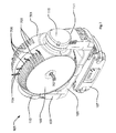
- FIG. 1 shows a first possible embodiment for the invention.
- a moving head light fixture 101 comprises a head 103 which head is rotatably supported in a yoke 105.
- the yoke 105 is rotatably supported by a base 107.
- the yoke 105 comprises a first arm 109 and a second arm 111, where which first arm 109 ends in a bearing 113 and which second arm 111 ends in a bearing 115.
- the bearings 113 and 115 are carrying the head 103.
- the moving head 103 in the illustrated embodiment is barrel shaped and comprises an end section 119 seen from the front.
- Moving head 103 is covered by an outer shell 121 with cooling fins 122.
- There are also a number of blowholes 120 on the surface of the outer shell 121 which will help the heat be led from the inside to the outside.
- Figure 1 also shows the air flow direction through the light fixture, and it can be seen that air is led as illustrated by arrow 125 into the fixture at one end 119 of the light fixture and led out of as illustrated by arrows 127 through blowholes 120 of the light fixture.
- Figure 2 illustrates an exploded perspective view of the first possible embodiment of the moving head light fixture according to the invention with double-sided light emitting ends.
- the light fixture comprises a base 107, a yoke 105 and the moving head comprises two light generating parts 201a, 201 b capable of emitting light. The details of the light generating parts are described in figure 3 and 4 .
- Figure 3 illustrates an exploded perspective view of a half 201 a of the above double-side moving head light fixture 101 of the first embodiment of the present invention.
- the other half 201 b of the moving head 103 has the identical components as illustrated in Fig.3 .
- Fig.3 For the symmetrical structure, only the light generating parts 201 a in Fig.2 are illustrated in Fig.3 and described below.
- the first light generating parts 201 a comprises a first cooling plate 302a, comprising a number of PCB 309a (print circuits boards) with LEDs are placed; a second cooling plate 304a comprising a number of electronic circuits 311 a for LED control; and an air flow passage 305a running through said first cooling plate 302a and expanding along the axes of the moving head 103 to the front cover 317a.
- the front cover 317a is in the shown embodiment transparent and the light from the LED would thus pass through the front cover.
- the front cover could also be formed as a color filter and/or any kind of optical lens.
- the illustrated moving head comprises four electronic circuits 309a with LEDs, which are displayed above the first cooling plate 302a and four electrical circuits for LED control which are arranged beneath the second cooling plate 304a.
- the skilled person would realize that any number of electronic circuits could be used.
- a lens array 315a is positioned corresponding to the LEDs and deflects the light emitted by the LED.
- a holder 313a with a number of holes which are capable of supporting the lens array 315a is further arranged above the LEDs.
- a number of spacers 307a are located between the first and second cooling plate 302a and 304a and wind generator 328a is positioned between said first cooling plate 302a and said second cooling plate 304a.
- the wind generator is in one embodiment a centrifugal fan that sucks air into the moving heat from the front as illustrated by the arrow 125 and "throws" the air between the first 302a and second 304a cooling plate, where the air passes as illustrated by the arrows 308a around the spacers.
- light generating parts 201 a and 201 b are covered by a first outer shell 321 a and a second outer shell (not shown in the Fig.3 ).
- a plurality of fins 122 are comb shaped formed along both the first and second shells respectively, and the fins from both shells interlocked each other when the first outer shell 321 a and second outer shell are joined.
- some blowholes 120 are formed on the first outer shell 321 a and second outer shell. Therefore, the heat dissipating effect is enhanced by the fan 328a as air would leave the moving head through the blowholes 120.
- Fig. 4 illustrates an enlarged exploded perspective view of the cooling module 400 of the moving head of the present invention.
- the first cooling plate 302a and said second cooling plate 304a are connected by a number of spacers 307a.
- Spacer 307a is ear shaped and forms a cavity 401 a.
- the wires from LED PCB 309a and control PCB 311 a could be arranged more orderly in the cavities respectively whereby dust and moist are prevented from polluting the electrical connections.
- a centrifugal fan (not shown in figure 4 ) could be positioned between the first 302a and the second 304a cooling plates as illustrated in fig 3 .
- the centrifugal fan would suck air through the first cooling plate 302a and throw the air out between the two cooling plates similar to the embodiment illustrated in figure 3 .
- the second cooling plate 304a comprises in this embodiment also an air passage 403a and it is thus possible to suck air from both sides of the cooling plates or lead some of the air through the second cooling plate.
- Fig.5 illustrates an exploded perspective view of one half of another embodiment of a moving head light fixture according to the present invention.
- This embodiment comprises a first cooling plate 302a comprising a number of PCB (not shown)); a second cooling plate 304a comprising a number of electronic circuits (not shown) for LED control; an lens array 315a and a lens holder 313a and air flow passage 305a running through said first cooling plate 302a and expanding along the axes of the moving head to the front cover 317a.
- a number of spacers 501 a are positioned under the first cooling plate 302a and form a group of helix shaped fins, where a pluralities of paths 503a are formed, which are capable of increasing the air flow efficiency.
- FIG. 6 illustrates a perspective view of another embodiment of a moving head light fixture with fins protruding outward from the outer shell of the present invention.
- a moving head light fixture 101 comprises a head 103 which head is rotatably supported in a yoke 105. Said yoke 105 is rotatably supported by a base 107.
- the yoke 105 comprises a first arm 109, a second arm 111 which first arm 109 ends in a bearing 113 which second arm 111 ends in a bearing 115.
- the bearings 113 and 115 are carrying the head 103.
- the moving head 103 in the illustrated embodiment is barrel shaped and comprises an end section 119 seen from the front.
- the lenses 20, 22 and 24 are forming three concentric circles at the figure 6 .
- Moving head 103 is covered by outer shell 121. Outside of the moving head 103 is formed a plurality of cooling fins 601. Said fins 601 are arranged parallel each other and protruding outward from the outer shell 121. These fins 601 are forming a very powerful heat sink. There will be extremely good airflow between the fins and in that way effective cooling is achieved.
- the spacer 307a and the cooling plate 302a, 304a of all the embodiments could be constructed as one component. Or the spacer and cooling plates could be constructed as two separate objects where the spacer is attached to the cooling plates by attaching means, such as glue, screws, magnetic force, welding etc.
- FIG. 7 shows a yet another embodiment for the invention.
- a moving head light fixture 101 comprises a head 103 which head is rotatable supported in a yoke 105.
- the yoke 105 is rotatable supported by a base 107.
- the yoke 105 comprises a first arm 109 and a second arm 111, where which first arm 109 ends in a bearing 113 and which second arm 111 ends in a bearing 115.
- the bearings 113 and 115 are carrying the head 103.
- Moving head 103 is covered by an outer shell 701 with cooling fins 703. There are also a number of blowholes 705 on the surface of the outer shell 701 which will help the heat to be led from the inside to the outside.
- Figure 7 also shows the air flow direction through the light fixture, and it can be seen that air is led as illustrated by arrow 707 into the fixture at one end of the light fixture 101 and led out of as illustrated by arrows 709 through blowholes 705 of the light fixture.
- Fig. 8 illustrates a perspective view of the moving head light fixture of fig 7 where one half 801 a of the moving head has been exploded and where the other half 801 b is identical to the first half.
- the skilled person would however realize that the two halves do not need to be identical and they can be constructed different in order to create different light og effects the sides of the moving head.
- the first half 801a comprises a cooling module 803 according to the present invention.
- the cooling module 803 comprises a first cooling plate 302a, comprising a number of PCBs 309a (print circuits boards) where LEDs are placed; a second cooling plate 304a comprising a number of electronic circuits (not shown, but the corresponding electronic circuit 311 b on the second half can be seen) for LED control.
- the drawing illustrates only one PCB board 309a with LEDs (not shown) and only one electronic ciruits for led control 311b, but the skilled person would realize that any number of these components could be used.
- the moving head comprises further an air flow passage 305a running from the front cover 317a at one end of the moving head through a lens array 315a, through the first cooling plate 302a and between the first and second cooling plates. Air would be let in to the air passage 305a at the front cover 317a as illustrated by arrow 707 and flow through the air passage 305a as illustrated by arrows 805. The air would then be let out between the cooling plates as illustrated by arrows 807 and thereafter out of the moving head through the blow holes of the outer shell as illustrated by arrows 709.
- the illustrated embodiment comprises a centrifugal fan (not shown) which sucks the air as illustrated by arrows 805 through the air passage 305a and directs the air out as illustrated by arrows 807 between the first and second cooling plate.
- the front cover 317a is transparent in the shown embodiment and the light from the LED would thus pass through the front cover.
- the front cover could also be formed as a color filter and/or any kind of optical lens.
- a lens array 315a is positioned corresponding to the LEDs and deflects the light emitted by the LED.
- a holder 313a with a number of holes which are capable of supporting the lens array 315a is further arranged above the LEDs.
- the cooling module 803 is similar to the once described above.
- the moving head comprises an outer shell comprising four parts 701 a 701 b 701 c and 701d. Each part comprises a plurality of fins and blow holes.
Description
- The present invention relates to a moving head light fixture, which moving head light fixture comprises a light generating head, which head is carried in a yoke, which head is rotatable to the yoke, which yoke is rotatable to a base, which head comprises electronic circuits for LED control.
- The present invention further relates to a cooling module for a moving head light fixture.
- Light fixtures currently tend to use light sources with a high lumen, and the light sources are thus provided with high power. The light sources are getting more and more efficient and uses more and more of the supplied energy to generate light; however a considerable part of the power is still generated into heat. For example, arrayed LEDs (light-emitting diode) in a light fixture may have such high power as 500 watts. In this case, it is desired to have a light device with a heat-dissipating system, which works fast and efficiently.
- The pending patent
US 2005219841 disclosed an illuminating device and projection type video display where three primary colors light sources are provided as a light source. Each light source is a light source in which pluralities of LEDs (light-emitting diodes) are arranged in the same plane surface. The three light sources are arranged on the same plane surface. Furthermore, lines connecting the three light sources form a triangle. Light fluxes (primary optical axes) of each light source are parallel with each other. The three light sources are arranged on one piece of a cooling plate. Further, a wind generator is arranged in such a manner as to be surrounded by said three solid light sources, and air taken in by said wind generator is blown to said cooling plate. Generally, a fan is used in a light device in order to dissipate the heat generated by the light device. However, for the three light sources are arranged on the same plane, the disadvantage of the above illuminating device and projection type video display is the size of the light device is large and the light sources of the device are not movable, thus, the cooling system above-described could not applied in the light fixture with moving head. The space in a moving head is further very limited compared to the Illuminating device and projection type video display ofUS2005219841 , and the electronic circuits for LED control thus are positioned very close to the LEDs, and a further demand on cooling is needed, since the LED control circuits also generate heat. -
WO 2009/033051 A1 (published on 12/03/2009 , with a claimed priority from 07/09/2007) discloses a cooling module for a moving head light fixture, where air is directed by a wind generator from an external part of the module towards the centre part. -
EP202599 - The object of the present invention is to solve the above described problems.
- This can be achieved by a cooling module for a head light fixture according to claim 1.
- Herby it is possible to create a compact moving head light fixture where both the LEDs and electronic drive circuits are effectively cooled. This is achieved by positioning the LEDs on the first cooling plate and the electronic circuit for LED control on the second cooling plate. The air flow passage makes it possible to lead air between the cooling plates, as the air passage runs through at least one of the cooling plates and forms a tunnel between the first and second cooling plates, which is helpful for the air flow and whereby both the LEDs and electric circuits are cooled using the same air. The size of the light fixture could be more compressed, as both the LEDs and the electric circuits could be cooled using the same air. Moreover, the LEDs are placed on the first cooling plate and the electronic circuit for LED driving is arranged on the second cooling plate, thus the configuration is capable of directly conducting the heat produced by the LEDs and the driver respectively to an outer shell of the moving head. Further it is possible to cool the LEDs and electronic circuits for LED control from the inside and out, as the air passage runs through one on the cooling plates. This is advantageously, as the LEDs and the electronic circuits for LED control positioned at the centre of the cooling plates tend to be the hottest and by cooling from the inside and out makes sure that the hottest parts are cooled first. The position where the air passage goes through the cooling plates can thus be positioned at the near the hottest places.
- The moving head comprises a wind generator directing air through at least a part of said air flow passage. Hereby the wind generator can increase the speed of the air flow and the heat then can be dissipated more quickly.
- As an embodied solution, the wind generator is a centrifugal fan positioned between the first cooling plate and the second cooling plate. Hereby it achieves a quieter and more effective cooling effect. The centrifugal fan sucks air through one of the cooling plates from one end of the moving head and "throws" thereafter the air between the cooling plates by the blade tips. The air makes in other words a 90-degree-angle turn as it travels from the inlet to the outlet and is "thrown" from the blade tips. Generally, centrifugal fan is quieter than the axial fans. As the heat produced by the LEDs and electronic circuits for LED control are mainly concentrated near the center of the first and second cooling plate, where the fan is arranged, it is possible that the hottest part of the light fixture is cooled firstly.
- The first cooling plate and the second cooling plate are in another embodiment connected by at least one spacer. Hereby is achieved that the heat generated by the LEDs and the electric circuits for LED control would be removed more effective, as another heat dissipate way is created. When the spacer is made of a heat conducting material, such as aluminum, copper, any other kind of metal or alloy, then it is possible to form thermal conduction from the cooling plates to the spacer. Thus, except for the air flow by the fans, another way for heat conducting is created, and a more compact moving head light could be constructed. Moreover, the spacer is located between the first and second cooling plate, where a common used room containing the wirings from both the LEDs and the electrical circuit for LED could be provided. Therefore, quite advantageously, both the LEDs and electronic drive circuits are effectively cooled and the size of moving head light fixture is more compacted.
- In another embodiment of the present invention, the spacer provides at least one cavity between the first cooling plate and the second cooling plate. Hereby it is possible to protect the electronics from dust and moist, as the cavity provides a room for the wirings between the LEDs and the electrical circuit for LED control. When a plurality of cavities is formed on the spacer, the wirings are capable of being arranged more orderly in the limited space. The advantage is a more reducing space is formed. Another advantage is, the moving head generally comprises an outer shell for containing the LEDs and the electrical circuits, when the outer shell of the moving head has blowholes, the cavity is capable of preventing the dust and moist from contacting the wirings.
- In another embodiment of the present invention, the spacer is helix shaped and forms a plurality of air paths between said first cooling plate and said second cooling plate. Hereby it is possible to provide more effective cooling effect. When the space is helix shaped, it provides a plurality of paths for directing air flowing through helixes. The helix shaped spacers could e.g. be formed such that air from a centrifugal fan positioned between the cooling plates would be directed tangentially into the plurality of paths. The advantage is the hot air is easier to flowing from center to outsider, whereby a more efficient cooling is achieved.
- In another embodiment of the present invention, the moving head comprises a first outer shell and a second outer shell with a plurality of fins; said fins are comb shape formed along said first and second outer shell, which fins are overlapped each other when the first and second outer shell joined. Hereby an effective heat-dissipating outer shell is created. Blowholes will be formed on the outer shell, when the fins do not overlap each other entirely. The heat therefore could be blow from the inside of the moving head to the outside through these blowholes. Further, it could save more material for outer shell.
- The moving head light fixture comprises in another embodiment of the present invention at least one shell with a plurality of fins arranged parallel to each other and vertical protruding outward from the shell. Hereby it is possible to improve heat dissipating. A plurality fins formed on the outer shell is able to conduct more heat in the effectively way.
- In another embodiment of the present invention, at least a part of said spacers, said first cooling plate and/or said second cooling plate are connected to at least a part of said shell. Hereby it is possible to improve the heat dissipating of the moving head even further. The material of the spacer, the first cooling plate and/or the second cooling plate could be made of a heat conducting material, for example, aluminum, cooper or steel, any other kind of metal or alloy. When a part of said spacers, said first cooling plate and/or said second cooling plate are connected to at least a part of said shell, because of contact directly it is possible that thermal conduction is formed. Thermal conduction is the more effective manner than the heat transfer heat by convection and radiation. Therefore, the cooling effect is enhanced.
- The invention further relates to a cooling module for a moving head light fixture, which moving head light fixture comprises a light generating head, which head is carried in a yoke, which head is rotatable to the yoke, which yoke is rotatable to a base, which head comprises at least one electronic circuit for LED control, said cooling module comprises a first cooling plate comprising a number of LEDs; a second cooling plate comprising said at least one electronic circuit for LED control; and an air flow passage running from at least one end of said moving head, through at least said first cooling plate or said second cooling plate and between said first cooling plate and said second cooling plate.
- Hereby a compact cooling module for a moving head could be constructed and the same technical effects and advantages as described above are achieved. Further by the cooling module improves the serviceability of the moving head as it could be constructed as one module which easily could be remove from and replaced in the moving head. For instance in connection with service and/or cleaning.
- Further embodiments of the cooling module are described below and the same technical effects and advantages as described above are achieved by these embodiments.
- In another embodiment, said cooling module comprises a wind generator directing air through at least a part of said air flow passage.
- Further in one another embodiment said wind generator is a centrifugal fan positioned between said first cooling plate and said second cooling plate.
- Yet in another embodiment, the first cooling plate and the second cooling plate is connected by at least one spacer.
- In another embodiment, the spacer provides at least a cavity between said first cooling plate and said second cooling plate.
- As an alternate embodiment above, the spacer of the cooling module is helix shaped and forms a plurality of air paths between said first cooling plate and said second cooling plate.
-
-
Fig. 1 illustrates a perspective view of a moving head light fixture of the present invention; -
Fig. 2 illustrates an exploded perspective view of a double-sided moving head light fixture of an embodiment of the present invention; -
Fig. 3 illustrates an exploded perspective view of one half of the double-side moving head light fixture illustrated infigure 2 ; -
Fig. 4 illustrates an enlarged exploded perspective view of one half of the double-side moving head light fixture illustrated infigure 2 and3 ; -
Fig. 5 illustrates an enlarged exploded perspective view of one half of another embodiment of a double-side moving head light fixture; -
Fig. 6 illustrates a perspective view of another embodiment of a moving head light fixture with fins protruding from the outer shell of the present invention. -
Fig. 7 illustrates a perspective view of yet another embodiment of a moving head light fixture according to the present invention. -
Fig. 8 illustrates a perspective view of the moving head light fixture offig 7 where one half of the moving head has been exploded. -
Figure 1 shows a first possible embodiment for the invention. A movinghead light fixture 101 comprises ahead 103 which head is rotatably supported in ayoke 105. Theyoke 105 is rotatably supported by abase 107. Theyoke 105 comprises afirst arm 109 and asecond arm 111, where whichfirst arm 109 ends in abearing 113 and whichsecond arm 111 ends in abearing 115. Thebearings head 103. The movinghead 103 in the illustrated embodiment is barrel shaped and comprises anend section 119 seen from the front. Movinghead 103 is covered by anouter shell 121 with coolingfins 122. There are also a number ofblowholes 120 on the surface of theouter shell 121 which will help the heat be led from the inside to the outside. -
Figure 1 also shows the air flow direction through the light fixture, and it can be seen that air is led as illustrated byarrow 125 into the fixture at oneend 119 of the light fixture and led out of as illustrated byarrows 127 throughblowholes 120 of the light fixture. -
Figure 2 illustrates an exploded perspective view of the first possible embodiment of the moving head light fixture according to the invention with double-sided light emitting ends. The light fixture comprises abase 107, ayoke 105 and the moving head comprises twolight generating parts figure 3 and4 . -
Figure 3 illustrates an exploded perspective view of ahalf 201 a of the above double-side movinghead light fixture 101 of the first embodiment of the present invention. Theother half 201 b of the movinghead 103 has the identical components as illustrated inFig.3 . For the symmetrical structure, only thelight generating parts 201 a inFig.2 are illustrated inFig.3 and described below. The firstlight generating parts 201 a comprises afirst cooling plate 302a, comprising a number ofPCB 309a (print circuits boards) with LEDs are placed; asecond cooling plate 304a comprising a number ofelectronic circuits 311 a for LED control; and anair flow passage 305a running through saidfirst cooling plate 302a and expanding along the axes of the movinghead 103 to thefront cover 317a. Thefront cover 317a is in the shown embodiment transparent and the light from the LED would thus pass through the front cover. The front cover could also be formed as a color filter and/or any kind of optical lens. - The illustrated moving head comprises four
electronic circuits 309a with LEDs, which are displayed above thefirst cooling plate 302a and four electrical circuits for LED control which are arranged beneath thesecond cooling plate 304a. The skilled person would realize that any number of electronic circuits could be used. - A
lens array 315a is positioned corresponding to the LEDs and deflects the light emitted by the LED. Aholder 313a with a number of holes which are capable of supporting thelens array 315a is further arranged above the LEDs. A number ofspacers 307a are located between the first andsecond cooling plate wind generator 328a is positioned between saidfirst cooling plate 302a and saidsecond cooling plate 304a. The wind generator is in one embodiment a centrifugal fan that sucks air into the moving heat from the front as illustrated by thearrow 125 and "throws" the air between the first 302a and second 304a cooling plate, where the air passes as illustrated by thearrows 308a around the spacers. - As shown in
fig. 2 andfig. 3 ,light generating parts outer shell 321 a and a second outer shell (not shown in theFig.3 ). A plurality offins 122 are comb shaped formed along both the first and second shells respectively, and the fins from both shells interlocked each other when the firstouter shell 321 a and second outer shell are joined. When thefins 122 are not overlapped each other entirely, someblowholes 120 are formed on the firstouter shell 321 a and second outer shell. Therefore, the heat dissipating effect is enhanced by thefan 328a as air would leave the moving head through theblowholes 120. Further cooling could be applied, if the diameters of thefirst cooling plate 302a, thesecond cooling plate 304a and thespacer 307a are large enough to reach theouter shells 321 a directly, whereby heat could be conducted from the inside of the moving head to the outside of the moving head. -
Fig. 4 illustrates an enlarged exploded perspective view of thecooling module 400 of the moving head of the present invention. Thefirst cooling plate 302a and saidsecond cooling plate 304a are connected by a number of spacers 307a.Spacer 307a is ear shaped and forms acavity 401 a. The wires fromLED PCB 309a and controlPCB 311 a could be arranged more orderly in the cavities respectively whereby dust and moist are prevented from polluting the electrical connections. - A centrifugal fan (not shown in
figure 4 ) could be positioned between the first 302a and the second 304a cooling plates as illustrated infig 3 . The centrifugal fan would suck air through thefirst cooling plate 302a and throw the air out between the two cooling plates similar to the embodiment illustrated infigure 3 . Thesecond cooling plate 304a comprises in this embodiment also anair passage 403a and it is thus possible to suck air from both sides of the cooling plates or lead some of the air through the second cooling plate. -
Fig.5 illustrates an exploded perspective view of one half of another embodiment of a moving head light fixture according to the present invention. This embodiment comprises afirst cooling plate 302a comprising a number of PCB (not shown)); asecond cooling plate 304a comprising a number of electronic circuits (not shown) for LED control; anlens array 315a and alens holder 313a andair flow passage 305a running through saidfirst cooling plate 302a and expanding along the axes of the moving head to thefront cover 317a. - A number of
spacers 501 a are positioned under thefirst cooling plate 302a and form a group of helix shaped fins, where a pluralities ofpaths 503a are formed, which are capable of increasing the air flow efficiency. -
Fig. 6 illustrates a perspective view of another embodiment of a moving head light fixture with fins protruding outward from the outer shell of the present invention. A movinghead light fixture 101 comprises ahead 103 which head is rotatably supported in ayoke 105. Saidyoke 105 is rotatably supported by abase 107. Theyoke 105 comprises afirst arm 109, asecond arm 111 whichfirst arm 109 ends in abearing 113 whichsecond arm 111 ends in abearing 115. Thebearings head 103. The movinghead 103 in the illustrated embodiment is barrel shaped and comprises anend section 119 seen from the front. Thelenses 20, 22 and 24 are forming three concentric circles at thefigure 6 . In the centre of thefront end section 119 is indicated afan 221. Movinghead 103 is covered byouter shell 121. Outside of the movinghead 103 is formed a plurality of coolingfins 601. Saidfins 601 are arranged parallel each other and protruding outward from theouter shell 121. Thesefins 601 are forming a very powerful heat sink. There will be extremely good airflow between the fins and in that way effective cooling is achieved. - The
spacer 307a and thecooling plate -
Figure 7 shows a yet another embodiment for the invention. A movinghead light fixture 101 comprises ahead 103 which head is rotatable supported in ayoke 105. Theyoke 105 is rotatable supported by abase 107. Theyoke 105 comprises afirst arm 109 and asecond arm 111, where whichfirst arm 109 ends in abearing 113 and whichsecond arm 111 ends in abearing 115. Thebearings head 103. Movinghead 103 is covered by anouter shell 701 with coolingfins 703. There are also a number ofblowholes 705 on the surface of theouter shell 701 which will help the heat to be led from the inside to the outside. -
Figure 7 also shows the air flow direction through the light fixture, and it can be seen that air is led as illustrated byarrow 707 into the fixture at one end of thelight fixture 101 and led out of as illustrated byarrows 709 throughblowholes 705 of the light fixture. -
Fig. 8 illustrates a perspective view of the moving head light fixture offig 7 where onehalf 801 a of the moving head has been exploded and where theother half 801 b is identical to the first half. The skilled person would however realize that the two halves do not need to be identical and they can be constructed different in order to create different light og effects the sides of the moving head. - The
first half 801a comprises acooling module 803 according to the present invention. Thecooling module 803 comprises afirst cooling plate 302a, comprising a number ofPCBs 309a (print circuits boards) where LEDs are placed; asecond cooling plate 304a comprising a number of electronic circuits (not shown, but the correspondingelectronic circuit 311 b on the second half can be seen) for LED control. The drawing illustrates only onePCB board 309a with LEDs (not shown) and only one electronic ciruits for ledcontrol 311b, but the skilled person would realize that any number of these components could be used. The moving head comprises further anair flow passage 305a running from thefront cover 317a at one end of the moving head through alens array 315a, through thefirst cooling plate 302a and between the first and second cooling plates. Air would be let in to theair passage 305a at thefront cover 317a as illustrated byarrow 707 and flow through theair passage 305a as illustrated byarrows 805. The air would then be let out between the cooling plates as illustrated byarrows 807 and thereafter out of the moving head through the blow holes of the outer shell as illustrated byarrows 709. The illustrated embodiment comprises a centrifugal fan (not shown) which sucks the air as illustrated byarrows 805 through theair passage 305a and directs the air out as illustrated byarrows 807 between the first and second cooling plate. - The
front cover 317a is transparent in the shown embodiment and the light from the LED would thus pass through the front cover. The front cover could also be formed as a color filter and/or any kind of optical lens. - A
lens array 315a is positioned corresponding to the LEDs and deflects the light emitted by the LED. Aholder 313a with a number of holes which are capable of supporting thelens array 315a is further arranged above the LEDs. Thecooling module 803 is similar to the once described above. The moving head comprises an outer shell comprising fourparts 701 a 701b - Although the present invention was discussed in terms of certain preferred embodiments, the invention is not limited to such embodiments. A person of ordinary skill in the art will appreciate that numerous variations and combinations of the features set forth above can be utilized without departing from the present invention as set forth in the claims. Thus, the scope of the invention should not be limited by the preceding description but should be ascertained by reference to claims that follow.
Claims (8)
- A cooling module for a moving head light fixture (101), which moving head light fixture comprises a light generating head (103), which head is carried in a yoke (105), which head is rotatable to the yoke, which yoke is rotatable to a base (107), which head comprises electronic circuits for led control, said cooling module comprises:• a first cooling plate (302a) comprising a number of LEDs;• a second cooling plate (304a) comprising said at least one electronic circuit for LED control;• an air flow passage (305a) running from at least one end of said moving head, through at least said first cooling plate and/or said second cooling plate and between said first cooling plate and said second cooling plate;• a wind generator (328a) directing air through at least a part of said air flow passage;wherein said wind generator is adapted to direct said air through at least said first cooling plat and/or said second cooling plate and thereafter direct said air from the inside and out and between said first cooling plate and said second cooling plate.
- A cooling module according to claim 1 characterized in that said wind generator is a centrifugal fan positioned between said first cooling plate and said second cooling plate.
- A cooling module according to any one of the claims 1-2 characterized in that said first cooling plate and said second cooling plate being connected by at least one spacer (307a).
- A cooling module according to claim 3 characterized in that said spacer provides at least one cavity (401 a) between said first cooling plate and said second cooling plate.
- A cooling module according to claim 4 characterized in said spacer is helix shaped (501 a) and forms a plurality of air paths (503a) between said first cooling plate and said second cooling plate.
- Moving head light fixture (101), which moving head light fixture comprises a light generating head (103), which head is carried in a yoke (105), which head is rotatable to the yoke, which yoke is rotatable to a base (107), which head comprises at least one electronic circuit for LED control, characterized in that said moving head comprises a cooling module according to any one of claims 1-5.
- A moving head according to any one of the claim 6 characterized in that said moving head light fixture comprises at least one shell (321 a) with a plurality fins (122) of protruding outward from the shell.
- A moving head according to any one of the claim 6-7, characterized in that at least a part of said spacers, said first cooling plate and/or said second cooling plate are connected to at least a part of said shell.
Applications Claiming Priority (2)
| Application Number | Priority Date | Filing Date | Title |
|---|---|---|---|
| DKPA200801819 | 2008-12-19 | ||
| PCT/DK2009/050337 WO2010069327A1 (en) | 2008-12-19 | 2009-12-15 | Moving head fixture and cooling module |
Publications (3)
| Publication Number | Publication Date |
|---|---|
| EP2359056A1 EP2359056A1 (en) | 2011-08-24 |
| EP2359056A4 EP2359056A4 (en) | 2013-08-28 |
| EP2359056B1 true EP2359056B1 (en) | 2015-04-22 |
Family
ID=42268339
Family Applications (1)
| Application Number | Title | Priority Date | Filing Date |
|---|---|---|---|
| EP20090832958 Active EP2359056B1 (en) | 2008-12-19 | 2009-12-15 | Moving head fixture and cooling module |
Country Status (5)
| Country | Link |
|---|---|
| US (1) | US8596836B2 (en) |
| EP (1) | EP2359056B1 (en) |
| CN (1) | CN102257320B (en) |
| DK (1) | DK2359056T3 (en) |
| WO (1) | WO2010069327A1 (en) |
Families Citing this family (26)
| Publication number | Priority date | Publication date | Assignee | Title |
|---|---|---|---|---|
| US8708535B2 (en) * | 2010-02-16 | 2014-04-29 | Martin Professional A/S | Illumination device with interlocked yoke shell parts |
| US8911116B2 (en) | 2011-04-01 | 2014-12-16 | Cooper Technologies Company | Light-emitting diode (LED) floodlight |
| US8485691B2 (en) * | 2011-05-13 | 2013-07-16 | Lumenpulse Lighting, Inc. | High powered light emitting diode lighting unit |
| WO2012167798A1 (en) * | 2011-06-10 | 2012-12-13 | Martin Professional A/S | Illumination device with multi-layered heat sink |
| US9605843B2 (en) | 2011-07-11 | 2017-03-28 | Golight, Inc. | LED system and housing for use with halogen light |
| WO2013016582A2 (en) * | 2011-07-26 | 2013-01-31 | Golight, Inc. | Multi-face rotatable housing and mounting platform |
| CN103782095A (en) | 2011-09-08 | 2014-05-07 | 格莱特有限公司 | Rotatable optical device housing and mounting platform |
| CN103244919B (en) | 2012-02-06 | 2015-04-01 | 马丁专业公司 | Base element for moving head light fixture |
| US8888336B2 (en) | 2012-02-29 | 2014-11-18 | Phoseon Technology, Inc. | Air deflectors for heat management in a lighting module |
| US20140016317A1 (en) * | 2012-07-16 | 2014-01-16 | Jst Performance, Inc. Dba Rigid Industries | Landing light |
| JP6341638B2 (en) * | 2013-07-30 | 2018-06-13 | キヤノン株式会社 | Lighting device |
| US9353924B2 (en) | 2014-01-10 | 2016-05-31 | Cooper Technologies Company | Assembly systems for modular light fixtures |
| US9383090B2 (en) | 2014-01-10 | 2016-07-05 | Cooper Technologies Company | Floodlights with multi-path cooling |
| EP2927579B1 (en) | 2014-04-04 | 2020-02-12 | Harman Professional Denmark ApS | Cooling module for led light fixture |
| CN204005325U (en) * | 2014-05-27 | 2014-12-10 | 广州盛龙照明有限公司 | A kind of multi-functional module type lamp |
| US20180156430A1 (en) * | 2014-11-20 | 2018-06-07 | Sgm Light A/S | Moving head lamp |
| CN104373851B (en) * | 2014-12-01 | 2016-05-25 | 东莞勤上光电股份有限公司 | A kind of radiator and there is the LED light fixture of this radiator |
| TWM503078U (en) * | 2015-01-09 | 2015-06-11 | Micro Star Int Co Ltd | Liquid-cooling heat dissipation device |
| US10113725B2 (en) * | 2015-03-20 | 2018-10-30 | Energy Bank Incorporated | Lighting fixture |
| US10018337B2 (en) * | 2015-12-10 | 2018-07-10 | Milwaukee Electric Tool Corporation | Flood light |
| CN107314257B (en) * | 2017-08-24 | 2023-09-19 | 浙江锐迪生光电有限公司 | LED filament lamp without metal radiator and working method thereof |
| US10436435B2 (en) * | 2017-10-24 | 2019-10-08 | Jiasheng Wu | High intensity illumination LED work light assembly |
| US11938859B2 (en) | 2019-11-15 | 2024-03-26 | Golight, Inc. | Searchlight system for vehicle post |
| US11073268B1 (en) * | 2020-10-27 | 2021-07-27 | GVM Photographic Equipment Inc. | Double-sided LED panel light |
| USD957507S1 (en) | 2021-04-14 | 2022-07-12 | ZhiSheng Xu | Double-sided on-camera light with cold shoe head |
| US11577856B1 (en) | 2022-02-28 | 2023-02-14 | Honeywell International Inc. | Dual sided aircraft light assembly |
Family Cites Families (17)
| Publication number | Priority date | Publication date | Assignee | Title |
|---|---|---|---|---|
| JP3069819B2 (en) * | 1992-05-28 | 2000-07-24 | 富士通株式会社 | Heat sink, heat sink fixture used for the heat sink, and portable electronic device using the heat sink |
| DE20007235U1 (en) | 1999-05-19 | 2000-07-27 | Agon Tech Corp | General purpose lamp |
| TW556916U (en) * | 1999-05-19 | 2003-10-01 | Agon Tech Corp | Improved structure of illumination lamp |
| GB0114222D0 (en) * | 2001-06-12 | 2001-08-01 | Pulsar Light Of Cambridge Ltd | Lighting unit with improved cooling |
| US6749310B2 (en) * | 2001-09-07 | 2004-06-15 | Contrast Lighting Services, Inc. | Wide area lighting effects system |
| US7604361B2 (en) * | 2001-09-07 | 2009-10-20 | Litepanels Llc | Versatile lighting apparatus and associated kit |
| GB0209069D0 (en) * | 2002-04-20 | 2002-05-29 | Ewington Christopher D | Lighting module |
| US20050169015A1 (en) * | 2003-09-18 | 2005-08-04 | Luk John F. | LED color changing luminaire and track light system |
| CN100383455C (en) * | 2004-04-22 | 2008-04-23 | 中国科学院上海光学精密机械研究所 | Controllable LED stage lights |
| US7144140B2 (en) * | 2005-02-25 | 2006-12-05 | Tsung-Ting Sun | Heat dissipating apparatus for lighting utility |
| JP4611857B2 (en) * | 2005-10-11 | 2011-01-12 | 本田技研工業株式会社 | motor |
| US7985005B2 (en) * | 2006-05-30 | 2011-07-26 | Journée Lighting, Inc. | Lighting assembly and light module for same |
| US20080247874A1 (en) * | 2007-04-05 | 2008-10-09 | Acre James A | Dual flow fan heat sink application |
| US7959330B2 (en) | 2007-08-13 | 2011-06-14 | Yasuki Hashimoto | Power LED lighting assembly |
| EP2201286A1 (en) * | 2007-09-07 | 2010-06-30 | Philips Solid-State Lighting Solutions | Methods and apparatus for providing led-based spotlight illumination in stage lighting applications |
| CN201093265Y (en) * | 2007-09-29 | 2008-07-30 | 艾元平 | Light projector |
| CN201246718Y (en) * | 2008-07-22 | 2009-05-27 | 大和灯具工业股份有限公司 | LED illuminating apparatus |
-
2009
- 2009-12-15 DK DK09832958.4T patent/DK2359056T3/en active
- 2009-12-15 EP EP20090832958 patent/EP2359056B1/en active Active
- 2009-12-15 WO PCT/DK2009/050337 patent/WO2010069327A1/en active Application Filing
- 2009-12-15 US US13/133,173 patent/US8596836B2/en active Active
- 2009-12-15 CN CN200980150776.9A patent/CN102257320B/en active Active
Also Published As
| Publication number | Publication date |
|---|---|
| CN102257320A (en) | 2011-11-23 |
| WO2010069327A1 (en) | 2010-06-24 |
| US20110235330A1 (en) | 2011-09-29 |
| EP2359056A4 (en) | 2013-08-28 |
| US8596836B2 (en) | 2013-12-03 |
| CN102257320B (en) | 2015-11-25 |
| DK2359056T3 (en) | 2015-06-01 |
| EP2359056A1 (en) | 2011-08-24 |
Similar Documents
| Publication | Publication Date | Title |
|---|---|---|
| EP2359056B1 (en) | Moving head fixture and cooling module | |
| US7637635B2 (en) | LED lamp with a heat sink | |
| US7758214B2 (en) | LED lamp | |
| JP5597500B2 (en) | Light emitting module and vehicle lamp | |
| JP5295683B2 (en) | Power LED lighting device | |
| JP2011187264A (en) | Lighting system | |
| JP6199970B2 (en) | Heat dissipation structure with segmented chimney structure | |
| EP2480829B1 (en) | A lighting device | |
| TWI408312B (en) | Lamp | |
| EP2541140B1 (en) | Lighting device | |
| US20100328949A1 (en) | Illumination device | |
| US20120218774A1 (en) | Led light bulb | |
| JP6341949B2 (en) | LED lighting device | |
| JP5499475B2 (en) | Lamp device and lighting device | |
| JP4657364B1 (en) | LED light source device | |
| US7520640B1 (en) | LED wall lamp with a heat sink | |
| JP6116567B2 (en) | Lighting device | |
| JP5847574B2 (en) | High-speed illuminator | |
| JP3181991U (en) | Light emitting diode lamp | |
| WO2011107979A1 (en) | Led lamp fitting having an integral cooling fan | |
| JP2015212997A (en) | Lighting device | |
| JP6985801B2 (en) | Lighting equipment | |
| KR101833221B1 (en) | Lighting device | |
| JP2021144849A (en) | Illuminating device | |
| TWI416041B (en) | Lamp structure |
Legal Events
| Date | Code | Title | Description |
|---|---|---|---|
| PUAI | Public reference made under article 153(3) epc to a published international application that has entered the european phase |
Free format text: ORIGINAL CODE: 0009012 |
|
| 17P | Request for examination filed |
Effective date: 20110601 |
|
| AK | Designated contracting states |
Kind code of ref document: A1 Designated state(s): AT BE BG CH CY CZ DE DK EE ES FI FR GB GR HR HU IE IS IT LI LT LU LV MC MK MT NL NO PL PT RO SE SI SK SM TR |
|
| DAX | Request for extension of the european patent (deleted) | ||
| A4 | Supplementary search report drawn up and despatched |
Effective date: 20130730 |
|
| RIC1 | Information provided on ipc code assigned before grant |
Ipc: F21Y 101/02 20060101ALN20130724BHEP Ipc: F21V 29/02 20060101AFI20130724BHEP Ipc: F21V 21/30 20060101ALI20130724BHEP Ipc: F21W 131/406 20060101ALN20130724BHEP |
|
| RIC1 | Information provided on ipc code assigned before grant |
Ipc: F21V 21/30 20060101ALI20140702BHEP Ipc: F21V 29/02 20060101AFI20140702BHEP Ipc: F21W 131/406 20060101ALN20140702BHEP Ipc: F21Y 101/02 20060101ALN20140702BHEP |
|
| GRAP | Despatch of communication of intention to grant a patent |
Free format text: ORIGINAL CODE: EPIDOSNIGR1 |
|
| RIC1 | Information provided on ipc code assigned before grant |
Ipc: F21W 131/406 20060101ALN20140918BHEP Ipc: F21V 21/30 20060101ALI20140918BHEP Ipc: F21V 29/02 20060101AFI20140918BHEP Ipc: F21Y 101/02 20060101ALN20140918BHEP |
|
| INTG | Intention to grant announced |
Effective date: 20141013 |
|
| GRAS | Grant fee paid |
Free format text: ORIGINAL CODE: EPIDOSNIGR3 |
|
| REG | Reference to a national code |
Ref country code: DE Ref legal event code: R079 Ref document number: 602009030881 Country of ref document: DE Free format text: PREVIOUS MAIN CLASS: F21V0029020000 Ipc: F21V0029600000 |
|
| GRAA | (expected) grant |
Free format text: ORIGINAL CODE: 0009210 |
|
| RIC1 | Information provided on ipc code assigned before grant |
Ipc: F21V 21/30 20060101ALI20150223BHEP Ipc: F21W 131/406 20060101ALN20150223BHEP Ipc: F21Y 101/02 20060101ALN20150223BHEP Ipc: F21V 29/60 20150101AFI20150223BHEP |
|
| RAP1 | Party data changed (applicant data changed or rights of an application transferred) |
Owner name: MARTIN PROFESSIONAL APS |
|
| AK | Designated contracting states |
Kind code of ref document: B1 Designated state(s): AT BE BG CH CY CZ DE DK EE ES FI FR GB GR HR HU IE IS IT LI LT LU LV MC MK MT NL NO PL PT RO SE SI SK SM TR |
|
| REG | Reference to a national code |
Ref country code: GB Ref legal event code: FG4D |
|
| REG | Reference to a national code |
Ref country code: CH Ref legal event code: EP |
|
| REG | Reference to a national code |
Ref country code: AT Ref legal event code: REF Ref document number: 723462 Country of ref document: AT Kind code of ref document: T Effective date: 20150515 |
|
| REG | Reference to a national code |
Ref country code: IE Ref legal event code: FG4D |
|
| REG | Reference to a national code |
Ref country code: DK Ref legal event code: T3 Effective date: 20150527 |
|
| REG | Reference to a national code |
Ref country code: DE Ref legal event code: R096 Ref document number: 602009030881 Country of ref document: DE Effective date: 20150603 |
|
| REG | Reference to a national code |
Ref country code: NL Ref legal event code: VDEP Effective date: 20150422 |
|
| REG | Reference to a national code |
Ref country code: AT Ref legal event code: MK05 Ref document number: 723462 Country of ref document: AT Kind code of ref document: T Effective date: 20150422 |
|
| REG | Reference to a national code |
Ref country code: LT Ref legal event code: MG4D |
|
| PG25 | Lapsed in a contracting state [announced via postgrant information from national office to epo] |
Ref country code: NL Free format text: LAPSE BECAUSE OF FAILURE TO SUBMIT A TRANSLATION OF THE DESCRIPTION OR TO PAY THE FEE WITHIN THE PRESCRIBED TIME-LIMIT Effective date: 20150422 |
|
| PG25 | Lapsed in a contracting state [announced via postgrant information from national office to epo] |
Ref country code: FI Free format text: LAPSE BECAUSE OF FAILURE TO SUBMIT A TRANSLATION OF THE DESCRIPTION OR TO PAY THE FEE WITHIN THE PRESCRIBED TIME-LIMIT Effective date: 20150422 Ref country code: NO Free format text: LAPSE BECAUSE OF FAILURE TO SUBMIT A TRANSLATION OF THE DESCRIPTION OR TO PAY THE FEE WITHIN THE PRESCRIBED TIME-LIMIT Effective date: 20150722 Ref country code: LT Free format text: LAPSE BECAUSE OF FAILURE TO SUBMIT A TRANSLATION OF THE DESCRIPTION OR TO PAY THE FEE WITHIN THE PRESCRIBED TIME-LIMIT Effective date: 20150422 Ref country code: ES Free format text: LAPSE BECAUSE OF FAILURE TO SUBMIT A TRANSLATION OF THE DESCRIPTION OR TO PAY THE FEE WITHIN THE PRESCRIBED TIME-LIMIT Effective date: 20150422 Ref country code: HR Free format text: LAPSE BECAUSE OF FAILURE TO SUBMIT A TRANSLATION OF THE DESCRIPTION OR TO PAY THE FEE WITHIN THE PRESCRIBED TIME-LIMIT Effective date: 20150422 Ref country code: PT Free format text: LAPSE BECAUSE OF FAILURE TO SUBMIT A TRANSLATION OF THE DESCRIPTION OR TO PAY THE FEE WITHIN THE PRESCRIBED TIME-LIMIT Effective date: 20150824 |
|
| PG25 | Lapsed in a contracting state [announced via postgrant information from national office to epo] |
Ref country code: GR Free format text: LAPSE BECAUSE OF FAILURE TO SUBMIT A TRANSLATION OF THE DESCRIPTION OR TO PAY THE FEE WITHIN THE PRESCRIBED TIME-LIMIT Effective date: 20150723 Ref country code: LV Free format text: LAPSE BECAUSE OF FAILURE TO SUBMIT A TRANSLATION OF THE DESCRIPTION OR TO PAY THE FEE WITHIN THE PRESCRIBED TIME-LIMIT Effective date: 20150422 Ref country code: AT Free format text: LAPSE BECAUSE OF FAILURE TO SUBMIT A TRANSLATION OF THE DESCRIPTION OR TO PAY THE FEE WITHIN THE PRESCRIBED TIME-LIMIT Effective date: 20150422 Ref country code: IS Free format text: LAPSE BECAUSE OF FAILURE TO SUBMIT A TRANSLATION OF THE DESCRIPTION OR TO PAY THE FEE WITHIN THE PRESCRIBED TIME-LIMIT Effective date: 20150822 |
|
| REG | Reference to a national code |
Ref country code: FR Ref legal event code: PLFP Year of fee payment: 7 |
|
| REG | Reference to a national code |
Ref country code: DE Ref legal event code: R097 Ref document number: 602009030881 Country of ref document: DE |
|
| PG25 | Lapsed in a contracting state [announced via postgrant information from national office to epo] |
Ref country code: EE Free format text: LAPSE BECAUSE OF FAILURE TO SUBMIT A TRANSLATION OF THE DESCRIPTION OR TO PAY THE FEE WITHIN THE PRESCRIBED TIME-LIMIT Effective date: 20150422 |
|
| PLBE | No opposition filed within time limit |
Free format text: ORIGINAL CODE: 0009261 |
|
| STAA | Information on the status of an ep patent application or granted ep patent |
Free format text: STATUS: NO OPPOSITION FILED WITHIN TIME LIMIT |
|
| PG25 | Lapsed in a contracting state [announced via postgrant information from national office to epo] |
Ref country code: RO Free format text: LAPSE BECAUSE OF NON-PAYMENT OF DUE FEES Effective date: 20150422 Ref country code: SK Free format text: LAPSE BECAUSE OF FAILURE TO SUBMIT A TRANSLATION OF THE DESCRIPTION OR TO PAY THE FEE WITHIN THE PRESCRIBED TIME-LIMIT Effective date: 20150422 Ref country code: PL Free format text: LAPSE BECAUSE OF FAILURE TO SUBMIT A TRANSLATION OF THE DESCRIPTION OR TO PAY THE FEE WITHIN THE PRESCRIBED TIME-LIMIT Effective date: 20150422 |
|
| 26N | No opposition filed |
Effective date: 20160125 |
|
| PG25 | Lapsed in a contracting state [announced via postgrant information from national office to epo] |
Ref country code: BE Free format text: LAPSE BECAUSE OF NON-PAYMENT OF DUE FEES Effective date: 20151231 Ref country code: SI Free format text: LAPSE BECAUSE OF FAILURE TO SUBMIT A TRANSLATION OF THE DESCRIPTION OR TO PAY THE FEE WITHIN THE PRESCRIBED TIME-LIMIT Effective date: 20150422 |
|
| PG25 | Lapsed in a contracting state [announced via postgrant information from national office to epo] |
Ref country code: MC Free format text: LAPSE BECAUSE OF FAILURE TO SUBMIT A TRANSLATION OF THE DESCRIPTION OR TO PAY THE FEE WITHIN THE PRESCRIBED TIME-LIMIT Effective date: 20150422 Ref country code: LU Free format text: LAPSE BECAUSE OF FAILURE TO SUBMIT A TRANSLATION OF THE DESCRIPTION OR TO PAY THE FEE WITHIN THE PRESCRIBED TIME-LIMIT Effective date: 20151215 |
|
| REG | Reference to a national code |
Ref country code: CH Ref legal event code: PL |
|
| PG25 | Lapsed in a contracting state [announced via postgrant information from national office to epo] |
Ref country code: BE Free format text: LAPSE BECAUSE OF FAILURE TO SUBMIT A TRANSLATION OF THE DESCRIPTION OR TO PAY THE FEE WITHIN THE PRESCRIBED TIME-LIMIT Effective date: 20150422 |
|
| REG | Reference to a national code |
Ref country code: IE Ref legal event code: MM4A |
|
| PG25 | Lapsed in a contracting state [announced via postgrant information from national office to epo] |
Ref country code: CH Free format text: LAPSE BECAUSE OF NON-PAYMENT OF DUE FEES Effective date: 20151231 Ref country code: IE Free format text: LAPSE BECAUSE OF NON-PAYMENT OF DUE FEES Effective date: 20151215 Ref country code: LI Free format text: LAPSE BECAUSE OF NON-PAYMENT OF DUE FEES Effective date: 20151231 |
|
| REG | Reference to a national code |
Ref country code: FR Ref legal event code: PLFP Year of fee payment: 8 |
|
| PG25 | Lapsed in a contracting state [announced via postgrant information from national office to epo] |
Ref country code: IT Free format text: LAPSE BECAUSE OF NON-PAYMENT OF DUE FEES Effective date: 20151215 |
|
| PG25 | Lapsed in a contracting state [announced via postgrant information from national office to epo] |
Ref country code: SM Free format text: LAPSE BECAUSE OF FAILURE TO SUBMIT A TRANSLATION OF THE DESCRIPTION OR TO PAY THE FEE WITHIN THE PRESCRIBED TIME-LIMIT Effective date: 20150422 Ref country code: HU Free format text: LAPSE BECAUSE OF FAILURE TO SUBMIT A TRANSLATION OF THE DESCRIPTION OR TO PAY THE FEE WITHIN THE PRESCRIBED TIME-LIMIT; INVALID AB INITIO Effective date: 20091215 Ref country code: BG Free format text: LAPSE BECAUSE OF FAILURE TO SUBMIT A TRANSLATION OF THE DESCRIPTION OR TO PAY THE FEE WITHIN THE PRESCRIBED TIME-LIMIT Effective date: 20150422 |
|
| PG25 | Lapsed in a contracting state [announced via postgrant information from national office to epo] |
Ref country code: SE Free format text: LAPSE BECAUSE OF FAILURE TO SUBMIT A TRANSLATION OF THE DESCRIPTION OR TO PAY THE FEE WITHIN THE PRESCRIBED TIME-LIMIT Effective date: 20150422 Ref country code: CY Free format text: LAPSE BECAUSE OF FAILURE TO SUBMIT A TRANSLATION OF THE DESCRIPTION OR TO PAY THE FEE WITHIN THE PRESCRIBED TIME-LIMIT Effective date: 20150422 |
|
| PG25 | Lapsed in a contracting state [announced via postgrant information from national office to epo] |
Ref country code: MT Free format text: LAPSE BECAUSE OF FAILURE TO SUBMIT A TRANSLATION OF THE DESCRIPTION OR TO PAY THE FEE WITHIN THE PRESCRIBED TIME-LIMIT Effective date: 20150422 Ref country code: TR Free format text: LAPSE BECAUSE OF FAILURE TO SUBMIT A TRANSLATION OF THE DESCRIPTION OR TO PAY THE FEE WITHIN THE PRESCRIBED TIME-LIMIT Effective date: 20150422 Ref country code: IT Free format text: LAPSE BECAUSE OF NON-PAYMENT OF DUE FEES Effective date: 20151215 |
|
| PGRI | Patent reinstated in contracting state [announced from national office to epo] |
Ref country code: IT Effective date: 20170710 |
|
| REG | Reference to a national code |
Ref country code: FR Ref legal event code: PLFP Year of fee payment: 9 |
|
| PG25 | Lapsed in a contracting state [announced via postgrant information from national office to epo] |
Ref country code: MK Free format text: LAPSE BECAUSE OF FAILURE TO SUBMIT A TRANSLATION OF THE DESCRIPTION OR TO PAY THE FEE WITHIN THE PRESCRIBED TIME-LIMIT Effective date: 20150422 |
|
| REG | Reference to a national code |
Ref country code: DE Ref legal event code: R081 Ref document number: 602009030881 Country of ref document: DE Owner name: HARMAN PROFESSIONAL DENMARK APS, DK Free format text: FORMER OWNER: MARTIN PROFESSIONAL APS, ARHUS, DK |
|
| RIC2 | Information provided on ipc code assigned after grant |
Ipc: F21V 29/60 20150101AFI20150223BHEP Ipc: F21W 131/406 20060101ALN20150223BHEP Ipc: F21V 21/30 20060101ALI20150223BHEP Ipc: F21Y 101/02 20000101ALN20150223BHEP |
|
| PGFP | Annual fee paid to national office [announced via postgrant information from national office to epo] |
Ref country code: IT Payment date: 20201123 Year of fee payment: 12 Ref country code: DK Payment date: 20201123 Year of fee payment: 12 Ref country code: CZ Payment date: 20201124 Year of fee payment: 12 Ref country code: FR Payment date: 20201120 Year of fee payment: 12 |
|
| REG | Reference to a national code |
Ref country code: DK Ref legal event code: EBP Effective date: 20211231 |
|
| PG25 | Lapsed in a contracting state [announced via postgrant information from national office to epo] |
Ref country code: CZ Free format text: LAPSE BECAUSE OF NON-PAYMENT OF DUE FEES Effective date: 20211215 |
|
| PG25 | Lapsed in a contracting state [announced via postgrant information from national office to epo] |
Ref country code: FR Free format text: LAPSE BECAUSE OF NON-PAYMENT OF DUE FEES Effective date: 20211231 |
|
| PG25 | Lapsed in a contracting state [announced via postgrant information from national office to epo] |
Ref country code: DK Free format text: LAPSE BECAUSE OF NON-PAYMENT OF DUE FEES Effective date: 20211231 |
|
| PG25 | Lapsed in a contracting state [announced via postgrant information from national office to epo] |
Ref country code: IT Free format text: LAPSE BECAUSE OF NON-PAYMENT OF DUE FEES Effective date: 20211231 |
|
| P01 | Opt-out of the competence of the unified patent court (upc) registered |
Effective date: 20230527 |
|
| PGFP | Annual fee paid to national office [announced via postgrant information from national office to epo] |
Ref country code: GB Payment date: 20231124 Year of fee payment: 15 |
|
| PGFP | Annual fee paid to national office [announced via postgrant information from national office to epo] |
Ref country code: DE Payment date: 20231121 Year of fee payment: 15 |