EP2357718B1 - Armature coil of rotating electric machine - Google Patents
Armature coil of rotating electric machine Download PDFInfo
- Publication number
- EP2357718B1 EP2357718B1 EP09826171.2A EP09826171A EP2357718B1 EP 2357718 B1 EP2357718 B1 EP 2357718B1 EP 09826171 A EP09826171 A EP 09826171A EP 2357718 B1 EP2357718 B1 EP 2357718B1
- Authority
- EP
- European Patent Office
- Prior art keywords
- coil
- coil piece
- phase
- piece
- pieces
- Prior art date
- Legal status (The legal status is an assumption and is not a legal conclusion. Google has not performed a legal analysis and makes no representation as to the accuracy of the status listed.)
- Active
Links
- 238000004804 winding Methods 0.000 claims description 235
- 239000004020 conductor Substances 0.000 claims description 147
- 230000007935 neutral effect Effects 0.000 claims description 33
- 239000011295 pitch Substances 0.000 description 136
- 238000012986 modification Methods 0.000 description 56
- 230000004048 modification Effects 0.000 description 56
- 230000003247 decreasing effect Effects 0.000 description 16
- 238000009413 insulation Methods 0.000 description 13
- 230000007423 decrease Effects 0.000 description 6
- 238000001816 cooling Methods 0.000 description 5
- XEEYBQQBJWHFJM-UHFFFAOYSA-N Iron Chemical group [Fe] XEEYBQQBJWHFJM-UHFFFAOYSA-N 0.000 description 3
- 238000000034 method Methods 0.000 description 3
- 239000000470 constituent Substances 0.000 description 2
- 239000002826 coolant Substances 0.000 description 2
- 230000000694 effects Effects 0.000 description 2
- 230000005684 electric field Effects 0.000 description 2
- 239000011810 insulating material Substances 0.000 description 2
- 239000012212 insulator Substances 0.000 description 2
- 238000012423 maintenance Methods 0.000 description 2
- 239000010445 mica Substances 0.000 description 2
- 229910052618 mica group Inorganic materials 0.000 description 2
- UFHFLCQGNIYNRP-UHFFFAOYSA-N Hydrogen Chemical compound [H][H] UFHFLCQGNIYNRP-UHFFFAOYSA-N 0.000 description 1
- 229910052774 Proactinium Inorganic materials 0.000 description 1
- 229910052770 Uranium Inorganic materials 0.000 description 1
- 230000001174 ascending effect Effects 0.000 description 1
- 239000002801 charged material Substances 0.000 description 1
- 230000001419 dependent effect Effects 0.000 description 1
- 230000006866 deterioration Effects 0.000 description 1
- 230000004907 flux Effects 0.000 description 1
- 229910052739 hydrogen Inorganic materials 0.000 description 1
- 239000001257 hydrogen Substances 0.000 description 1
- 238000009434 installation Methods 0.000 description 1
- 150000002505 iron Chemical class 0.000 description 1
- 229910052745 lead Inorganic materials 0.000 description 1
- 239000000463 material Substances 0.000 description 1
- 238000013021 overheating Methods 0.000 description 1
- 238000005192 partition Methods 0.000 description 1
- 238000010248 power generation Methods 0.000 description 1
- 230000002265 prevention Effects 0.000 description 1
- 238000012546 transfer Methods 0.000 description 1
- 229910052721 tungsten Inorganic materials 0.000 description 1
- 229910052720 vanadium Inorganic materials 0.000 description 1
Images


Classifications
-
- H—ELECTRICITY
- H02—GENERATION; CONVERSION OR DISTRIBUTION OF ELECTRIC POWER
- H02K—DYNAMO-ELECTRIC MACHINES
- H02K3/00—Details of windings
- H02K3/04—Windings characterised by the conductor shape, form or construction, e.g. with bar conductors
- H02K3/28—Layout of windings or of connections between windings
-
- H—ELECTRICITY
- H02—GENERATION; CONVERSION OR DISTRIBUTION OF ELECTRIC POWER
- H02K—DYNAMO-ELECTRIC MACHINES
- H02K3/00—Details of windings
- H02K3/32—Windings characterised by the shape, form or construction of the insulation
- H02K3/40—Windings characterised by the shape, form or construction of the insulation for high voltage, e.g. affording protection against corona discharges
Definitions
- the invention relates to an armature winding of a rotating electrical machine, which is configured to prevent generation of corona discharge by reducing a potential difference between adjacent coil pieces.
- a conventional armature winding of a rotating electrical machine has a structure shown in FIG. 33 .
- FIG. 33 is a sectional view showing an example of an armature winding placed in a slot of an armature core of a rotating electrical machine.
- a reference number 12 denotes an armature core formed by stacking a laminated iron plate.
- An armature winding 14 is housed in a slot 13 provided in the circumference of the armature core 12.
- the armature winding 14 is provided in two layers of upper coil pieces 15 close to the slot opening, and lower coil pieces 16 close to the slot bottom, and the outer circumference is covered by a main insulating layer 24.
- An insulating plate 10a is provided at the slot bottom, and an insulating partition plate 10b is provided between the upper coil piece 15 and lower coil piece 16. A wedge 9 is inserted into the slot opening through an insulating plate 10c.
- the machine capacity is increased by increasing a generated voltage by connecting the upper and lower coil pieces 15 and 16 of the armature winding 14 in series.
- the thickness of the main insulating layer 24 of the armature winding is increased to withstand the voltage.
- a cross section of a conductor is decreased, a current density is increased, and a loss is increased.
- the armature winding is divided into multiple parallel circuits, the armature winding voltage is decreased without changing the machine capacity, and the thickness of the main insulating layer 24 is decreased, thereby decreasing the loss and increasing the cooling capacity.
- FIG. 34 is a developed perspective view of one phase of a 2-pole 3-phase 66-slot armature winding having two parallel circuits.
- FIG. 35 is a developed perspective view of three phases of the same armature winding shown in FIG. 34 . The other two phases not shown in FIG. 34 are obtained by displacing the configuration of the shown armature winding by 120° and 240°, respectively.
- the phase belt mentioned here means a part of a winding, which forms one same phase by dividing each of three phases into multiple parts, housing upper and lower coil pieces in two layers in multiple slots of an assigned laminated iron core (an armature core), and sequentially connecting them in series.
- the armature winding 14 of each phase has the upper coil piece 15 (15a, 15b) housed in a slot close to an opening, and the lower coil piece (16a, 16b) housed in a slot close to a bottom.
- the ends of the upper and lower coil pieces 15 and 16 are connected in series at a connection side coil end 19a connected to a lead-out portion of the winding, and at a counter-connection side coil end 19b that is axially opposite and not connected to a lead-out portion of the winding.
- the armature winding 14 has a first phase belt 17, in which each of the upper and lower coil pieces 15 and 16 are housed in eleven slots 13 (1 st to 11 th slots, and 28 th to 38 th slots) provided in the armature core 12, and a second phase belt 18, in which each of the upper and lower coil pieces 15 and 16 are housed in eleven slots 13 (34 th to 44 th slots, and 61 st to 5 th slots).
- the armature winding 14 of each phase has two parallel circuits, which are indicated by a solid line and a broken line.
- the upper coil piece 15 is connected to the corresponding lower coil piece 16 separated by a fixed pitch, at the connection side and counter-connection side coil ends 19a and 19b, thereby forming two parallel circuits.
- the parallel circuits are connected in parallel through a lead-out connection conductor 21 provided at the connection side coil end 19a, thereby forming the armature winding 14.
- an upper coil piece placed in the 1 st slot (the 1 st upper coil piece) is connected to a lower coil piece placed in the 28 th slot (the 28 th lower coil piece), and a coil pitch is 27.
- an upper coil piece placed in the 11 th slot (the 11 th upper coil piece) is connected to a lower coil piece placed in the 37 th slot (the 37 th lower coil piece), and a coil pitch is 26.
- a winding pitch means a pitch between the slot 13 housing the upper coil piece 15a of the first phase belt 17 and the slot 13 housing lower coil pieces, for example, and the winding pitch in FIG. 34 is 27.
- the upper and lower coil pieces are connected to have a coil pitch one less than a winding pitch at the connection side coil end, and a coil pitch equal to a winding pitch at the counter-connection side coil end.
- a lead-out portion is usually provided at the end of a phase belt, and a conductor of the lead-out portion is connected to a coil piece at the phase belt end.
- the lead-out connection conductor 21 connected to the output terminal 22 is connected to the 1 st coil piece of the upper coil piece 15a, and the 38 th coil piece of the lower coil piece 16a is connected to the lead-out connection conductor 21, and further connected to a neutral terminal 23.
- the lead-out connection conductor 21 connected to the output terminal 22 is connected to the 5 th coil piece of the lower coil piece 16a, and the 34 th coil piece of the upper coil piece 15b is connected to the lead-out connection conductor 21, and further connected to the neutral terminal 23.
- the centers of magnetic pole Pa and Pb are defined as shown in FIG. 34 , and in the first phase belt, the 1 st upper coil piece is called an upper coil piece positioned at the phase belt end far from the magnetic pole center, and the 11 th upper coil piece is called an upper coil piece positioned at the phase belt end close to the magnetic pole center.
- the 28 th lower coil piece is called a lower coil piece positioned at the phase belt end close to the magnetic pole center, and the 38 th lower coil piece is called a lower coil piece positioned at the phase belt end far from the magnetic pole center.
- the first upper coil piece that is an upper coil piece positioned at the phase belt end far from the magnetic pole center is connected to the 28 th lower coil piece that is a lower coil piece positioned at the phase belt end close to the magnetic pole center.
- coil pieces are sequentially wound from the left side to right side in FIG. 34 , namely from the 1 st upper coil piece to 28 th lower coil piece, 2 nd upper coil piece, and 29 th lower coil piece.
- this will be described as coil pieces wound so that upper coil pieces are positioned close to the magnetic pole center.
- the 5 th lower coil piece, 4 th upper coil piece, 4 th lower coil piece, and 43 rd upper coil piece coil pieces are wound so that lower coil pieces are positioned close to the magnetic pole center.
- a phase comprising the 1 st to 11 th upper coil pieces is called a V-phase
- a phase comprising the 12 th to 22 nd upper coil pieces is called a U-phase
- a phase comprising the 23 rd to 33 rd upper coil pieces is called a W-phase. This will be repeated in the following coil pieces. It is of course no problem if the configuration and sequence of the V, U and W phases are changed.
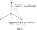
- the potential difference is indicated by p.u. as a ratio to an induced voltage in one phase.
- the potential of the upper coil piece placed in the 23 rd slot (the 23 rd upper coil piece) at the connection side end is 1[PU]
- the potential of the upper coil piece placed in the adjacent 22 nd slot (the 22 nd upper coil piece) is 10/11 [PU].
- FIG. 36 shows a vector indicating an example of the potential difference between the adjacent coil pieces in FIG. 35 .
- the potential difference between the 23 rd upper coil piece and 22 nd upper coil piece is 1.654 [PU] considering a phase difference.
- the potential of the 12 th upper coil piece at the connection side end is 0 [PU] at the connection side end, and the potential of the upper coil piece placed in the adjacent 11 th slot is 1/11 [PU].
- FIG. 37 shows the potential differences between adjacent coil pieces, particularly upper coil pieces, at the connection side coil end obtained as described above.
- the phases shown in legends indicate the phases of coil pieces to which smaller numbers are given.
- a maximum potential difference between adjacent coil pieces is 1.654 [PU] in the boundary of phase belts.
- FIG. 38 is a developed perspective view of one phase of a 2-pole 3-phase 66-slot armature winding having one parallel circuit.
- the number of slots occupied by each of the upper and lower coil pieces per one phase belt is 11, as in the armature winding shown in FIG. 34 .
- the winding pitch is 27, which is the same as the coil pitch 27 at the counter-connection side coil end 19b, and the coil pitch 26 at the connection side coil end 19a is one less than the winding pitch.
- a coil piece at the phase belt end is connected to a lead-out connection conductor.
- the 1 st coil piece of the upper coil piece 15a is connected to the lead-out connection conductor 21, and further connected to the output terminal 22, and at the connection side coil end 19a of the second phase belt 18, the 34 th coil piece of the upper coil piece 15b is connected to the lead-out connection conductor 21, and further connected to the neutral terminal 23.
- connection side jumper wire 20a The 38 th coil piece of the lower coil piece 16a in the first phase belt 17 and the 5 th coil piece of the lower coil piece 16b in the second phase belt 18 are connected by a connection side jumper wire 20a.
- the potential difference between adjacent coil pieces will be explained.
- the potential of the 44 th upper coil piece at the connection side end is 10/22 [PU]
- the potential of the not- shown adjacent 45 th upper coil piece is 1 [PU].
- the potential difference between the 44 th upper coil piece and 45 th upper coil piece is 1.289 [PU] considering a phase difference of 120°.
- FIG. 39 shows a potential difference between adjacent coil pieces at a connection side coil end.
- a maximum potential difference between adjacent coil pieces is 1.289 [PU] in the boundary of phase belts.
- FIG. 40 is a developed perspective view of one phase of an armature winding described in Patent document 4. This is a 2-pole 3-phase armature winding having 72 slots in an armature core. The number of slots per one phase belt occupied by each of the upper and lower coil pieces is 12.
- the armature winding comprises three parallel circuits, 1 to 3, indicated by three kinds of line in FIG. 40 .
- the parallel circuits of twelve upper coil pieces 15a and lower coil pieces 16a, constituting a first phase belt 17, are numbered 1, 2, 3, 1, 2, 3, 1, 2, 3, 1, 2, 3 sequentially from the left side, and similarly, the parallel circuits of twelve upper coil pieces 15b and lower coil pieces 16b, consisting a second phase belt, are numbered 3, 2, 1, 3, 2, 1, 3, 2, 1, 3, 2, 1, 3, 2, 1, 3, 2, 1, 3, 2, 1 sequentially from the left side, thereby decreasing a voltage deviation (an absolute value of deviation from an average phase voltage) in the parallel circuits and a phase deviation (a phase angle deviation from an average phase voltage) in the parallel circuits.
- the lead-out ends of the parallel circuits of the first and second phase belts 17 and 18 are connected by the lead-out connection conductor 21.
- the potential difference between adjacent coil pieces is 1.231 [PU] at maximum in the boundary of the phase belts, between the 1 st upper coil piece and not-shown 72 nd upper coil piece, for example.
- Patent document 5 describes an improvement to simplify the structure of an armature winding of a rotating electrical machine shown in the third example.
- FIG. 41 is a developed perspective view of one phase of an armature winding improved by the method described in patent document 5. This is a 2-pole 3-phase armature winding having 72 slots in an armature core. The number of slots per one phase belt occupied by each of the upper and lower coil pieces is 12.
- the armature winding comprises three parallel circuits, 1 to 3, indicated by three kinds of line in FIG. 40 .
- the parallel circuits of twelve upper coil pieces 15a and lower coil pieces 16a, consisting a first phase belt 17, are numbered 1, 2, 1, 1, 2, 1, 1, 2, 1, 1, 2, 1 sequentially from the left side.
- the parallel circuits of twelve upper coil pieces 15b and lower coil pieces 16b, consisting a second phase belt 18, are numbered 3, 2, 3, 3, 2, 3, 3, 2, 3, 2, 3, 2, 3, 2, 3, 2, 3, 2, 3, 2, 3 2, 3 sequentially from the left side.
- the parallel circuit 3 of the first phase belt and parallel circuit 1 of the second phase belt which are electrically equivalent, are interchanged so that the parallel circuits 1 and 3 are placed in the same phase belt.
- connection side lead-out end 19a is expanded by a 2-phase jumper wire 20a, and the lead-out terminals of the parallel circuits of the first and second phase belts 17 and 18 are connected by the lead-out connection conductor 21.
- the potential difference between adjacent coil pieces is 1.625 [PU] at maximum in the boundary of the phase belts, between the 1 st upper coil piece and not-shown 72 nd upper coil piece, for example.
- the potential difference between adjacent coil pieces is increased.
- the potential difference between adjacent coil pieces in the boundary of phase belts is increased, and corona discharge may occur during operation at the coil end in the boundary of phase belts.
- corona discharge occurs in an electric field of about 3kV/mm in air at a room temperature and atmospheric pressure, but actually, corona discharge may occur in a lower electric field, depending on the surface conditions of a charged material.
- patent document 1 improves corona resistance by winding a mica tape or sheet around a coil end, or the outside of a corona prevention layer.
- the corona resistant mica prevents corona discharge caused by the electric discharge, or decreases the insulation damage.
- the invention described in the patent document 1 decreases the insulation damage without changing the coil shape, whereas a tape or sheet is further wound around the outside of an insulated coil. This deteriorates heat transfer in the insulating material, and coil cooling effect, causing localized overheating. Further, the size, including the insulating material, is increased, the maintenance workability is lowered, and the armature may be accidentally damaged by maintenance.
- the coil end structure is restricted, and the coil group structure is complicated.
- the configuration is not suitable for a large-capacity rotating electrical machine such as a large turbine generator for thermal power generation.
- patent document 3 describes a 3-phase 4-pole 72-slot armature winding having three parallel circuits, in which coil pieces other than those at the ends of a phase belt are connected to a lead-out portion, and the voltage imbalance between the parallel circuits is reduced, and the potential difference between adjacent coils in the other phase is decreased on the connection side.
- patent document 3 aims at reducing the voltage imbalance between parallel circuits, and describes a winding method with specific numbers of poles, slots and parallel circuits. It does not decrease the potential difference from the coil pieces of the adjacent other phase, while keeping the same state as in conventional examples with respect to the voltage imbalance between parallel circuits.
- US 4 404 486 A discloses a star (wye) connected air gap polyphase armature having limited voltage differences between physically adjacent coil windings at the phase boundary for the different phase circuits.
- the unconnected lead of the coil or coils at the first edge of the phase belt region forms the neutral terminal for connection of the phase winding in a star or wye circuit comprised of other similarly formed phase windings, and the unconnected lead of the last coil or coils remaining at the middle of the phase belt region forms the line terminal for the multiple coil phase binding to thereby minimize voltage differences between turns of physically-adjacent phase windings at the phase boundaries.
- FIG. 1 is a developed perspective view of one phase of a first embodiment of an armature winding of a rotating electrical machine according to the invention.
- FIG. 2 is a developed perspective view of three phases of the same embodiment, in which two phases arranged by shifting an electric angle by 120° and 240° are added to one phase of the armature winding shown in FIG. 1 .
- an armature 11 of a rotating electrical machine has sixty-six slots 13 in an armature core 12 comprising a laminated iron core.
- armature core 12 comprising a laminated iron core.
- armature winding 14 is housed in two layers.
- the armature winding 14 of each phase has an upper coil piece 15 (15a and 15b) housed close to the slot opening, and a lower coil piece 16 (16a and 16b) housed close to the slot bottom.
- connection side coil end 19a connected to a lead-out portion of the winding
- counter-connection side coil end 19b that is axially opposite to the connection side coil end and not connected to a lead-out portion of the winding.
- the armature winding 14 has a first phase belt 17 in which each of the upper and lower coil pieces 15 and 16 are housed in eleven slots 13 (1 st to 11 th slots, and 28 th to 38 th slots) provided in the armature core 12, and a second phase belt 18 in which each of the upper and lower coil pieces 15 and 16 are housed in eleven slots 13 (34 th to 44 th slots, and 61 st to 5 th slots).
- the armature winding 14 of each phase has two parallel circuits.
- the parallel circuits are indicated by a solid line and a broken line, respectively.
- the upper coil piece 15 is connected to the corresponding lower coil pieces 16 separated by a fixed pitch, at the connection side end 19a and counter-connection side coil end 19b, thereby forming two parallel circuits.
- the parallel circuits are connected in parallel through the lead-out connection conductor 21 provided at the connection side coil end 19a, thereby forming the armature winding 14.
- the upper coil piece placed in the first slot (the 1 st coil piece) is connected to the lower coil piece placed in the 28 th slot (the 28 th lower coil piece), and the coil pitch 27.
- the 11 th upper coil piece is connected to the 37 th lower coil piece, and the coil pitch is 26.
- the winding pitch is 27, and the coil pitch at the connection side coil end is one less than the winding pitch, and the coil pitch at the counter-connection side coil end is equal to the winding pitch.
- the coil piece housed in the second slot from the end of a phase belt is connected to a lead-out portion.
- the lead-out connection conductor 21 connected to the output terminal 22 is connected to the 2 nd upper coil piece 15a, and sequentially wound from the 2 nd upper coil piece to 29 th lower coil piece, 3 rd upper coil piece, and 30 th lower coil piece, so that the upper coil pieces are positioned close to the magnetic pole center, and the 38 th lower coil piece that is the phase belt end of the lower coil piece far from the magnetic pole of the first phase belt 17 is connected to the 1 st upper coil piece that is the phase belt end of the upper coil piece far from the magnetic pole, by the jumper wire 20a.
- the 1 st upper coil piece is connected to the 28 th lower coil piece positioned at the phase belt end of the lower coil piece close to the magnetic pole, and further connected to the neutral terminal 23 through the lead-out connection conductor 21.
- the lead-out connection conductor 21 connected to the output terminal 22 is connected to the lower coil piece 16b, and sequentially wound from the 4 th lower coil piece to 44 th upper coil piece, 3 rd lower coil piece, and 43 rd upper coil piece, so that the lower coil pieces are positioned close to the magnetic pole center, and the 34 th upper coil piece that is the phase belt end of the upper coil piece far from the magnetic pole is connected to the 5 th lower coil piece that is the phase belt end of the lower coil far from the magnetic pole center, by the jumper wire 20a.
- the 4 th lower coil piece is connected to the 44 th upper coil piece, and the 44 th coil piece is connected to the neutral terminal 23 through the lead-out connection conductor 21.
- the structure of this embodiment is different from that described in the patent document 3 in a point that a jumper wire used to connect coil pieces in one phase belt is not present in the same phase belt to which a lead-out portion is connected, and the jumper wire connects coil pieces other than those at the end of the phase belt.
- Table 1 shows the potentials of upper and lower coil pieces at the connection side coil end in the first embodiment, particularly for the first phase belt.
- Table 2 shows the potentials of upper and lower coil pieces at the connection side coil end in the first embodiment, particularly for the second phase belt.
- Table 1 Potentials of upper and lower coil pieces at the connection side coil end in the first embodiment (First phase belt)
- the potential of the upper coil placed in the 23 rd slot for example is 1/11 [PU] at the connection side end
- the potential of the upper coil piece placed in the adjacent 22 nd slot is 0 [PU].
- FIG. 3 shows a vector indicating an example of a potential difference between adjacent coil pieces in the first embodiment.
- the potential of the upper coil placed in the 12 th slot (the 12 th upper coil piece) is 1/11 [PU] at the connection side end, and the potential of the upper coil piece placed in the adjacent 11 th slot (the 11 th upper coil piece) is 2/11 [PU].
- the potential difference between the 12 th upper coil piece and 11 th upper coil piece is 0.241 [PU]
- the potential difference between adjacent coil pieces at the phase belt end can be greatly reduced compared with conventional examples.
- FIG. 4 shows the potential differences between adjacent coil pieces, particularly upper coil pieces, at the connection side coil end obtained as described above.
- a maximum potential difference between adjacent coil pieces is 0.909 [PU], which is greatly reduced to about 55% of 1.654 [PU] of conventional examples, and prevents generation of corona discharge.
- FIG. 5 is a developed perspective view of one phase of a modification of the first embodiment.
- FIG. 6 is a developed perspective view of three phases of the same modification.
- the lead-out connection conductors 21 connected to adjacent three upper coil pieces and three lower coil pieces are closely arranged as shown by an area 21x where lead-out connection conductors interfere with each other.
- connection conductors cause such problems as an electromagnetic force between currents flowing in the conductors, and an increase in eddy-current loss in adjacent conductors caused by currents flowing in the conductors. Further, the insulating tape wound around the conductors may deteriorate, leading to insufficient insulation of the conductors.
- the coil piece housed in the 4 th slot from a phase belt end is connected to a lead-out portion.
- the lead-out connection conductor 21 connected to the output terminal 22 is connected to the 4 th upper coil piece 15a, and the 30 th lower coil piece 16a is connected to the lead-out connection conductor 21, and further connected to the neutral terminal 23.
- first upper coil piece 15a positioned at the phase belt end far from the magnetic pole center of the first phase belt 17 is connected to the 38 th lower coil piece 16a positioned at the phase belt end far from the magnetic pole center of the first phase belt 17, by the jumper wire 20a.
- the lead-out connection conductor 21 connected to the output terminal 22 is connected to the 2 nd upper coil piece 16a, and the 32 nd lower coil piece 15a is connected to the neutral terminal 23 through the lead-out connection conductor 21.
- the 34th upper coil piece 15a positioned at the phase belt end far from the magnetic pole center of the second phase belt 18 is connected to the 5 th lower coil piece 16a positioned at the phase belt end far from the magnetic pole center of the second phase belt 18, by the jumper wire 20a.
- coil pieces are sequentially wound so that upper coil pieces are positioned close to the magnetic pole center, in the first phase belt 17, and coil pieces are sequentially wound so that lower coil pieces are positioned close to the magnetic pole center, in the second phase belt 18.
- the distance between the connecting portions of the coil piece and lead-out connection conductor 21 at the connection side coil end 19a can be increased as compared with the case of FIG. 2 .
- the potential of the upper coil piece positioned in the 23 rd slot is 3/11 [PU] at the connection side end
- the potential of the upper coil piece positioned in the adjacent 22 nd slot (the 22 nd upper coil piece) is 2/11 [PU].
- the potential of the upper coil positioned in the 12 th slot is 3/11 [PU] at the connection side end
- the potential of the upper coil piece positioned in the adjacent 11 th slot (the 11 th upper coil piece) is 4/11 [PU].
- the potential difference between the 12 th upper coil piece and 11 th upper coil piece is 0.553 [PU].
- the potential difference between adjacent coil pieces at the phase belt end is larger than that in the first embodiment, and can be greatly decreased as compared with conventional examples.
- the potential difference between coil pieces in the same phase for example the W-phase
- the potential of the 26 th upper coil piece is 1 [PU]
- the potential of the 25 th upper coil piece is 1/11 [PU].
- FIG. 7 shows the potential differences between adjacent upper coil pieces at the connection side coil end obtained as described above, as in FIG. 4 .
- a maximum potential difference between adjacent coil pieces is 0.909 [PU], which is greatly reduced to about 55% of 1.654 [PU] of conventional examples, as in the first embodiment, and prevents generation of corona discharge.
- the potential difference between adjacent coil pieces is decreased to below that in conventional examples, such problems as an electromagnetic force between currents flowing in the conductors caused by closely arranged connection conductors, an increase in eddy-current loss in adjacent conductors caused by currents flowing in the conductors, and poor insulation caused by deteriorated insulating tape wound around the conductor are solved, and a reliable armature of a rotating electrical machine can be provided.
- the coil pieces housed in the 2 nd and 4 th slots from a phase belt end are connected to a lead-out portion.
- Which coil piece in which slot, except at a phase belt end, is to be connected to a lead-out portion can be appropriately determined.
- a potential difference between phase belts is increased.
- FIG. 8 shows a relationship between a potential difference between phase belts and a slot position X to house a coil piece connected to a lead-out portion in the 2-pole 3-phase 66-slot rotating electrical machine described in this embodiment.
- a broken line indicates a maximum potential difference between coil pieces in a phase belt.
- X ⁇ 6 a maximum potential difference in the armature winding is equal to a maximum potential difference between coil pieces in a phase belt, and is constant.
- a potential difference between phase belts exceeds a maximum potential difference between coil pieces in a phase belt, and a potential difference between phase belts becomes a maximum potential difference in an armature winding.
- a slot position X to house a coil piece connected to a lead-out portion is desirably X ⁇ 6.
- the potential of a coil piece in the boundary of phase belts is expressed by X/N t [PU] and (X - 1)/N t -[PU], and a condition in which a potential difference between phase belts does not exceed a maximum potential difference between coil pieces in a phase belt is expressed by the following formula, which is arranged from a relation in which a vector difference in these potentials whose phase is difference by 120° is smaller than a maximum potential difference (N t - 1)/N t between coil pieces in a phase belt: 3 ⁇ X X ⁇ 1 > N t 2 ⁇ 2 N t
- the position of a coil piece connected to a lead-out connection conductor from a phase belt end is the same in the first and second phase belts.
- the position of a coil piece connected to a lead-out connection conductor from a phase belt end may be different in the first and second phase belts.
- the 4 th upper coil piece from the end of a phase belt is connected to a lead-out connection conductor in the first phase belt, as in the modification of the first embodiment ( FIG. 1 )
- the 2 nd lower coil piece from the end of a phase belt is connected to a lead-out connection conductor in the second phase belt, as in the first embodiment ( FIG. 5 )
- a total of four lead-out connection conductors are adjacent in upper and lower sides, and the interference between the lead-out connection conductors can be reduced as compared with that in the case of FIG. 1 .
- the number of parallel circuits in each phase belt of a winding is equal to the number of magnetic poles.
- the invention may be embodied as described above even if the number of parallel circuits in each phase belt of each winding is less than the number of magnetic poles, for example, as in a 2-pole 1-parallel-circuit or 4-pole 2-parallel-circuit winding, or if the number of parallel circuits in each phase belt is 1.5 times the number of magnetic poles, for example, as in a 2-pole 3-parallel-circuit or 4-pole 6-parallel circuit winding.
- FIG. 9 is a developed perspective view of one phase of a second embodiment of an armature winding of a rotating electrical machine according to the invention.
- the other two phases are configured by shifting the electric angle by 120° and 240°.
- An explanation of the same configuration as in FIG. 1 is omitted.
- an armature 11 of a rotating electrical machine has sixty-six slots 13 in an armature core 12 comprising a laminated iron core.
- armature core 12 comprising a laminated iron core.
- armature winding 14 is housed in two layers.
- the coil pitch at the connection side coil end 19a is 28, one higher than the winding pitch, and the coil pitch at the counter-connection side coil end 19b is 27, equal to the winding pitch.
- the lead-out connection conductor 21 connected to the output terminal 22 is connected to the 10 th upper coil piece 15a, and sequentially wound from the 10 th upper coil piece to 37 th lower coil piece, 9 th upper coil piece, and 36 th lower coil piece, so that the upper coil pieces are positioned away from the magnetic pole center, and the 28 th lower coil piece that is the phase belt end of the lower coil piece close to the magnetic pole center of the first phase belt 17 is connected to the 11 th upper coil piece that is the phase belt end of the upper coil piece close to the magnetic pole center, by the jumper wire 20a.
- the 11 th upper coil piece is connected to the 38 th lower coil piece at the phase belt end of a lower coil piece far from the magnetic pole center, and further connected to the lead-out connection conductor 21, and connected to the neutral terminal 23.
- the lead-out connection conductor 21 connected to the output terminal 22 is connected to the 62 nd lower coil piece 15a, and sequentially wound from the 62 nd lower coil piece to 35 th upper coil piece, 63 rd lower coil piece, and 36 th upper coil piece, so that the lower coil pieces are positioned away from the magnetic pole center, and the 44 th upper coil piece that is the phase belt end of the upper coil piece close to the magnetic pole center is connected to the 61 st lower coil piece that is the phase belt end of the lower coil piece close to the magnetic pole center, by the jumper wire 20a.
- the 61 st lower coil piece is connected to the 34 th upper coil piece at the phase belt end of an upper coil piece far from the magnetic pole center, and further connected to the lead-out connection conductor 21, and connected to the neutral terminal 23.
- the potential difference between adjacent coil pieces regarding the coil pieces at the phase belt end in FIG. 2 , the potential of the first upper coil piece is 2/11 [PU] at the connection side end, and the potential of the not-shown adjacent 66 th upper coil piece is 2/11 [PU].
- the potential difference between the 1 st upper coil piece and 66 th upper coil piece is 0.315 [PU].
- the potential difference between coil pieces in the same phase for example the W-phase
- the potential of the 32 nd upper coil piece is 1 [PU]
- the potential of the 33 rd upper coil piece is 1/11 [PU].
- a maximum potential difference between adjacent coil pieces is 0.909 [PU], which is greatly reduced to about 55% of 1.654 [PU] of conventional examples, and prevents generation of corona discharge.
- FIG. 10 is a developed perspective view of one phase of a third embodiment of an armature winding of a rotating electrical machine according to the invention.
- This is a 2-pole 3-phase 2-parallel-circuit armature winding having 66 slots in an armature core.
- the other two phases are configured by shifting the electric angle by 120° and 240°. An explanation of the same configuration as in FIG. 1 is omitted.
- the 1 st upper coil piece and 28 th lower coil piece are connected in the connection side, and the coil pitch is 27, equal to the winding pitch.
- the 2 nd upper coil piece and 28 th lower coil piece are connected, and the coil pitch is 26, one less than the winding pitch.
- the lead-out connection conductor 21 connected to the output terminal 22 is connected to the 10 th upper coil piece 15a, and sequentially wound from the 10 th upper coil piece to 36 th lower coil piece, 9 th upper coil piece, and 35 th lower coil piece, so that the upper coil pieces are positioned away from the magnetic pole center, and the 1 st upper coil piece 15a positioned at the phase belt end far from the magnetic pole center is connected to the 38 th lower coil piece 16a positioned at the phase belt end far from the magnetic pole center, by the counter-connection side jumper wire 20b.
- the 38 th lower coil piece is sequentially connected to the 11 th upper coil piece and 37 th lower coil piece positioned at the phase belt end of an upper coil piece close to the magnetic pole center, and further connected to the lead-out connection conductor 21, and connected to the neutral terminal 23.
- the lead-out connection conductor 21 connected to the output terminal 22 is connected to the 62 nd lower coil piece 16b, and sequentially wound from the 62 nd lower coil piece to 36 th upper coil piece, 63 rd lower coil piece, and 37 th upper coil piece, so that the lower coil pieces are positioned away from the magnetic pole center, and the 1 st upper coil piece 15a positioned at the phase belt end far from the magnetic pole and the 5 th lower coil piece 16a positioned at the phase belt end far from the magnetic pole are connected to the 34 th upper coil piece positioned at the phase belt end far from the magnetic pole center, by the counter-connection side jumper wire 20b.
- the 34 th upper coil piece is sequentially connected to the 61 st upper coil piece and 35 th upper coil piece positioned at the phase belt end of the lower coil piece close to the magnetic pole, and further connected to the lead-out connection conductor 21, and connected to the neutral terminal 23.
- the potential difference between adjacent coil pieces Regard the coil pieces at the phase belt end in FIG. 10 , the potential of the first upper coil piece is 2/11 [PU] at the connection side end, and the potential of the not-shown adjacent 66 th upper coil piece is 2/11 [PU].
- the potential difference between the 1 st upper coil piece and 66 th upper coil piece is 0.315 [PU] considering a phase difference.
- the potential difference between coil pieces in the same phase for example the W-phase
- the potential of the 32 nd upper coil piece is 1 [PU]
- the potential of the 33 rd upper coil piece is 1/11 [PU].
- a maximum potential difference between adjacent coil pieces is 0.909 [PU], which is greatly reduced to about 55% of 1.654 [PU] of conventional examples, and prevents generation of corona discharge.
- the jumper wire to connect the coil pieces in a phase belt can be placed on the counter-connection side, and the interference between the lead-out connection conductors can be reduced. Therefore, such problems as an electromagnetic force between currents flowing in the conductors caused by closely arranged connection conductors, an increase in eddy-current loss in adjacent conductors caused by currents flowing in the conductors, and poor insulation caused by deteriorated insulating tape wound around the conductor are solved. Therefore, a reliable armature of a rotating electrical machine can be provided.
- FIG. 11 is a developed perspective view of one phase of a 2-pole 3-phase 2-parallel-circuit armature winding, as a fourth embodiment of an armature winding of a rotating electrical machine according to the invention.
- the number of slots is 66.
- the other two phases are configured by shifting the electric angle by 120° and 240°. An explanation of the same configuration as in FIG. 1 is omitted.
- an odd number of series coils is wound in one phase of the winding, the coil pitch at the connection side coil end is 25, two less than the winding pitch, and the coil pitch at the counter-connection side coil end is 27, equal to the winding pitch.
- the second upper coil piece 15a is connected to the lead-out connection conductor 21 connected to the output terminal 22, and sequentially wound to the 29 th lower coil piece, 4 th upper coil piece, and 31 st lower coil piece with the above coil pitch, and the 37 th lower coil piece 16a is connected to the 1 st upper coil piece by the connection side jumper wire 20a.
- the 1 st upper coil piece is sequentially wound to the 28 th lower coil piece, 3 rd upper coil piece, and 30 th lower coil piece with the above pitch, and the 38 th lower coil piece is connected to the lead-out connection conductor 21, and further connected to the neutral terminal 23.
- the 4 th lower coil piece 16b is connected to the lead-out connection conductor 21 connected to the output terminal 22, and sequentially wound to the 43 rd upper coil piece, 2 nd lower coil piece, and 41 st upper coil piece with the above coil pitch, and the 35 th upper coil piece 16a is connected to the 5 th lower coil piece by the connection side jumper wire 20a.
- the 5 th lower coil piece is sequentially wound to the 44 th upper coil piece, 3 rd lower coil piece, and 42 nd upper coil piece with the above pitch, and the 34 th upper coil piece is connected to the lead-out connection conductor 21, and further connected to the neutral terminal 23.
- a jumper wire in a phase belt connects the coil pieces at the phase end.
- a jumper wire connects between a coil piece at one phase end and a coil piece at the second from the other phase belt end.
- the potential difference between adjacent coil pieces As for the potential difference between adjacent coil pieces, regarding the coil pieces at the phase belt end in FIG. 11 , the potential of the 1 st upper coil piece is 6/11 [PU] at the connection side end, and the potential of the not-shown adjacent 66 th upper coil piece is 5/11 [PU].
- the potential difference between the 1 st upper coil piece and 66 th upper coil piece is 0.867 [PU] considering a phase difference.
- the potential difference between coil pieces in the same phase is different from the first to third embodiments.
- the potential of the 31 st upper coil piece is 2/11 [PU]
- the potential of the 32 nd upper coil piece is 7/11 [PU]
- the potential difference between coil pieces in the same phase is one of the above potential differences.
- a maximum potential difference between adjacent coil pieces is 0.867 [PU], the value between coil pieces of different phases, which is smaller than 1.654 [PU] in conventional examples and any value in the armature windings explained in the first to third embodiments. This is very effective to prevent generation of corona discharge.
- FIG. 12 is a developed perspective view of three phases of the armature winding of the fourth embodiment.
- the winding may be composed of six rows of connection rings, which is only one line more than in conventional examples.
- the space to install the connection rings can be reduced, and the size of a rotating electrical machine can be reduced.
- the pitch at the connection side coil end is two less than the winding pitch, the length of the connection side coil end can be reduced.
- FIG. 13 is a developed perspective view of one phase of a 2-pole 3-phase 2-parallel-circuit armature winding as a modification of the fourth embodiment. Unlike the fourth embodiment shown in FIG. 11 , the number of slots is 60, and the number of series coils is 10. An explanation of the same configuration as in the embodiment shown in FIG. 1 is omitted.
- the winding pitch is 25, the coil pitch at the connection side coil end is 23, two less than the winding pitch, and the coil pitch at the counter-connection side coil end is 25, equal to the winding pitch.
- the second upper coil piece 15a is connected to the lead-out connection conductor 21 connected to the output terminal 22, and sequentially wound to the 27 th lower coil piece, 4 th upper coil piece, and 29 th lower coil piece with the above coil pitch, and the 35 th lower coil piece 16a positioned at the phase belt end is connected to the 1 st upper coil piece positioned at the other phase coil end, by the connection side jumper wire 20a.
- the 1 st upper coil piece is sequentially wound to the 26 th lower coil piece, 3 rd upper coil piece, and 28 th lower coil piece with the above pitch, and the 34 th lower coil piece is connected to the lead-out connection conductor 21, and further connected to the neutral terminal 23.
- the 4 th lower coil piece 16b is connected to the lead-out connection conductor 21 connected to the output terminal 22, and sequentially wound to the 39 th upper coil piece, 2 nd lower coil piece, and 37 th upper coil piece with the above coil pitch, and the 31 st upper coil piece 16a positioned at the phase belt end is connected to the 5 th lower coil piece positioned at the other phase belt end, by the connection side jumper wire 20a.
- the 5 th lower coil piece is sequentially wound to the 40 th upper coil piece, 3 rd lower coil piece, and 38 th upper coil piece with the above pitch, and the 31 st upper coil piece is connected to the lead-out connection conductor 21, and further connected to the neutral terminal 23.
- the number of series coils per one phase is an even number, unlike the fourth embodiment ( FIG. 11 ) in which the number of series coils per one phase is an odd number, and a jumper wire connects between a coil piece at one phase belt end and a coil piece at the second from the other phase belt end.
- the potential difference between adjacent coil pieces As for the potential difference between adjacent coil pieces, regarding the coil pieces at the phase belt end in FIG. 13 , the potential of the 1 st upper coil piece is 5/10 [PU] at the connection side end, and the potential of the not-shown adjacent 60 th upper coil piece is 4/10 [PU]. The potential difference between the 1 st upper coil piece and 66 th upper coil piece is 0.781 [PU] considering a phase difference.
- the potential of the 10 th upper coil piece is 6/10 [PU] at the connection side end, and the potential of the not-shown adjacent 11 th upper coil piece is 5/10 [PU].
- the potential difference between the 10 th upper coil piece and 11 th upper coil piece is 0.954 [PU] considering a phase difference.
- a maximum potential difference between adjacent coil pieces is calculated with respect to a winding similar to those described in the first to third embodiments.
- the calculated maximum potential difference is 0.9 [PU], which is smaller than the potential difference in this modification.
- the potential difference between coil pieces in the same phase for example the V-phase
- the potential of the 8 th upper coil piece is 7/10 [PU]
- the potential of the 9 th upper coil piece is 1/10 [PU]
- the potential difference between coil pieces in the same phase is one of the above potential differences.
- a maximum potential difference between adjacent coil pieces is 0.954 [PU], the value between coil pieces of different phases.
- FIG. 14 is a developed perspective view of one phase of a 2-pole 3-phase 2-parallel-circuit armature winding as a fifth embodiment of an armature winding of a rotating electrical machine according to the invention.
- the number of slots is 66.
- the other two phases are configured by shifting the electric angle by 120° and 240°. An explanation of the same configuration as the embodiment in FIG. 1 is omitted.
- the coil pitch at the connection side coil end is 25, two less than the winding pitch, and the coil pitch at the counter-connection side coil end is 27, equal to the winding pitch.
- the second upper coil piece 15a is connected to the lead-out connection conductor 21 connected to the output terminal 22, and sequentially wound to the 29 th lower coil piece, 4 th upper coil piece, and 31 st lower coil piece, up to the 37 th lower coil piece, with the above coil pitch, and the 37 th lower coil piece 16a is connected to the 11 th upper coil piece by the connection side jumper wire 20c equivalent to one coil pitch.
- the 11 th upper coil piece is connected to the 38 th lower coil piece, and the 38 th lower coil piece that is the phase belt end is connected to the 1 st upper coil piece that is the other phase end by the connection side jumper wire 20a equivalent to 10 coil pitches.
- the 1 st upper coil piece is sequentially wound to the 28 th lower coil piece, 3 rd upper coil piece, and 30 th lower coil piece with the above pitch, and the 36 th lower coil piece is connected to the lead-out connection conductor 21, and further connected to the neutral terminal 23.
- the coil pieces are connected as in the fourth embodiment.
- the potential difference between adjacent coil pieces regarding the coil pieces at the phase belt end shown in FIG. 11 , the potential of the first upper coil piece is 5/11 [PU] at the connection side end, and the potential of the not-shown adjacent 66 th upper coil piece is 5/11 [PU].
- the potential difference between the 1 st upper coil piece and 66 th upper coil piece is 0.787 [PU] considering a phase difference.
- the potential difference between coil pieces in the same phase for example the V-phase
- the potential of the 8 th upper coil piece is 8/11 [PU]
- the potential of the 9 th upper coil piece is 1/11 [PU]
- the potential difference between coil pieces in the same phase is one of the above potential differences.
- a maximum potential difference between adjacent coil pieces is 0.787 [PU], the value between coil pieces of different phases, which is smaller than 1.654 [PU] of conventional examples and any value in the armature windings explained in the first to fourth embodiments. This is very effective to prevent generation of corona discharge.
- the potential difference between coil pieces of different phases can be decreased by changing the potentials of coil pieces at a phase belt end by using a connection side jumper wire equivalent to one coil pitch in the first phase belt in the fourth embodiment.
- FIG. 15 is a developed perspective view of one phase of a 2-pole 3-phase 2-parallel-circuit armature winding as a sixth embodiment of an armature winding of a rotating electrical machine according to the invention.
- the number of slots is 60 as in the modification of the fourth embodiment.
- the coil pitch is 25, the coil pitch at the connection side coil end is 23, two less than the winding pitch, and the coil pitch at the counter-connection side coil end is 25, equal to the winding pitch.
- the 2 nd upper coil piece 15a is connected to the lead-out connection conductor 21 connected to the output terminal 22, and sequentially wound to the 27 th lower coil piece, 4 th upper coil piece, and 29 th lower coil piece with the above coil pitch.
- the 31 st lower coil piece 16a is connected to the 7 th upper coil piece by the connection side jumper wire 20c equivalent to one coil pitch.
- the 7 th upper coil piece is connected to the 32 nd lower coil piece with the above same coil pitch, and further connected to the 9 th upper coil piece and 34 th lower coil piece.
- the 34 th lower coil piece is connected to the 1 st upper coil piece positioned at the phase end with the jumper wire 20a equivalent to 10 coil pitches.
- the 1 st upper coil piece is sequentially wound to the 26 th lower coil piece, 3 rd upper coil piece, 28 th lower coil piece, 5 th upper coil piece, and 30 th lower coil piece with the above same coil pitch.
- the 30 th lower coil piece is connected to the 8 th upper coil piece by the connection side jumper wire 20c equivalent to one coil pitch.
- the 8 th upper coil piece is connected to the 33 rd lower coil piece with the above same coil pitch, and further connected to the 10 th upper coil piece, and 35 th lower coil piece.
- the 35 th lower coil piece is connected to the lead-out connection conductor 21, and further connected to the neutral terminal 23.
- the coil pieces are connected as in the modification of the fourth embodiment.
- the potential of the 1 st upper coil piece is 5/10 [PU] at the connection side end, and the potential of the not-shown adjacent 60 th upper coil piece is 4/10 [PU].
- the potential difference between the 1 st upper coil piece and 66 th upper coil piece is 0.781 [PU] considering a phase difference, as in the modification of the fourth embodiment.
- the potential of the 10 th upper coil piece is 1/10 [PU] at the connection side end, and the potential of the not-shown adjacent 11 th upper coil piece is 5/10 [PU].
- the potential difference between the 10 th upper coil piece and 11 th upper coil piece is 0.557 [PU] considering a phase difference.
- a maximum potential difference between adjacent coil pieces, in a 60-slot winding is smaller than 0.9 [PU] in the winding similar to those described in the first to third embodiments, and 0.954 [PU] in the modification 1 of the fourth embodiment.
- a maximum potential difference between adjacent coil pieces in the same phase is 0.6 [PU]
- a maximum potential difference between adjacent coil pieces is 0.781 [PU] the value between coil pieces of different phases.
- connection jumper wires each equivalent to one coil pitch, described in this embodiment are not limited to those shown in FIG. 15 , and the jumper wires are desirably placed apart away from the lead-out connection conductor 21 from the viewpoint of reducing the interference.
- FIG. 16 is a developed perspective view of one phase of a 2-pole 3-phase 2-parallel-circuit armature winding as a seventh embodiment of an armature winding of a rotating electrical machine according to the invention.
- the number of slots is 66.
- the coil pitch at the connection side coil end is 26, one less than the winding pitch, and the coil pitch at the counter-connection side coil end is 28, one higher than the winding pitch.
- the 2 nd upper coil piece 15a is connected to the lead-out connection conductor 21 connected to the output terminal 22, and sequentially wound to the 30 th lower coil piece, 4 th upper coil piece, and 32 nd lower coil piece, up to the 10 th upper coil piece, with the above coil pitch.
- the 10 th upper coil piece 15a that is second from the phase belt end is connected to the 28 th lower coil piece at the other phase end, by the counter-connection side jumper wire 20b equivalent to 10 coil pitches.
- the 28 th lower coil piece is connected to the 1 st upper coil piece on the connection side by the connection side jumper wire 20c equivalent to one coil pitch.
- the 1 st upper coil piece is connected to the 29 th lower coil piece, and sequentially wound to the 3 rd upper coil piece, and 31 st lower coil piece with the above coil pitch.
- the 38 th lower coil piece is connected to the 11 th upper coil piece on the counter-connection side by the counter-connection side jumper wire 20d equivalent to one coil pitch in the counter-connection side, and further connected to the lead-out connection conductor 21, and connected to the neutral terminal 23.
- the 4 th lower coil piece 16b is connected to the lead-out connection conductor 21 connected to the output terminal 22, at the connection side coil end 19a, and connected to the 43 rd upper coil piece on the connection side by the connection side jumper wire 20c equivalent to one coil pitch. Then, the 3 rd lower coil piece, 41 st upper coil piece, 1 st lower coil piece, and 39 th upper coil piece are sequentially wound with the above coil pitch, up to the 61 st lower coil piece. The 61 st lower coil piece at the phase belt end is connected to the 44 th upper coil piece positioned at the other phase belt end, by the counter-connection side jumper wire 20b equivalent to 11 coil pitches.
- the 44 th upper coil piece is connected to the 5 th lower coil piece by the connection side jumper wire 20c equivalent to one coil pitch in the connection side
- the 5 th lower/upper coil piece is connected to the 42 nd upper coil piece on the counter-connection side by the counter-connection side jumper wire 20d equivalent to one coil pitch in the counter connection side, and sequentially wound to the 2 nd lower coil piece, and 40 th upper coil piece with the above coil pitch
- the 34 th upper coil piece is connected to the lead-out connection conductor 21, and further connected to the neutral terminal 23.
- the potential difference between adjacent coil pieces As for the potential difference between adjacent coil pieces, regarding the coil pieces at the phase belt end shown in FIG. 11 , the potential of the 1 st upper coil piece is 6/11 [PU] at the connection side end, and the potential of the not-shown adjacent 66 th upper coil piece is 5/11 [PU].
- the potential difference between the 1 st upper coil piece and 66 th upper coil piece is 0.867 [PU] considering a phase difference.
- the potential difference between coil pieces in the same phase for example the V-phase
- the potential of the 8 th upper coil piece is 2/11 [PU]
- the potential of the 9 th upper coil piece is 7/11 [PU]
- the potential difference between coil pieces in the same phase is one of the above potential differences.
- a maximum potential difference between adjacent coil pieces is 0.867 [PU], the value between coil pieces of different phases, which is smaller than 1.654 [PU] of conventional examples. This is very effective to prevent generation of corona discharge, and a stable armature of a rotating electrical machine can be provided.
- FIG. 17 is a developed perspective view of three phases of an armature winding of a rotating electrical machine of this embodiment.
- the winding may be composed of five rows of connection rings, which is the same number as in conventional examples.
- connection ring placing space can be reduced, and the size of a rotating electrical machine can be reduced.
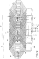
- FIG. 18 is a developed perspective view of one phase of a 2-pole 3-phase 2-parallel-circuit armature winding as an eighth embodiment of an armature winding of a rotating electrical machine according to the invention.
- the number of slots is 60.
- the configuration is basically the same as the seventh embodiment, except for some parts.
- the coil pitch at the connection side coil end is 24, one less than the winding pitch, and the coil pitch at the counter-connection side coil end is 26, one higher than the winding pitch.
- the 2 nd upper coil piece 15a is connected to the lead-out connection conductor 21 connected to the output terminal 22, and sequentially wound to the 28 th lower coil piece, 4 th upper coil piece, 30 th lower coil piece with the above coil pitch, and connected to the 10 th upper coil piece at the phase belt end, and then connected to the 26 th lower/upper coil piece by the counter-connection side jumper wire 20b equivalent to 10 coil pitches.
- the 26 th lower coil piece is connected to the 1 st upper coil piece by the connection side jumper wire 20c equivalent to one coil pitch, and sequentially connected to the 27 th lower coil piece, 3 rd upper coil piece, and 29 th lower coil piece with the above same coil pitch.
- the 35 th lower coil piece is connected to the lead-out connection conductor 21, and further connected to the neutral terminal 23.
- connection side jumper wire 20c equivalent to one oil pitch
- counter-connection side jumper wire 20b equivalent to 10 coil pitches
- the number of jumper wires is decreased, unlike the seventh embodiment ( FIG. 16 ) in which the number of series coils per one phase is an odd number.
- the potential difference between adjacent coil pieces As for the potential difference between adjacent coil pieces, regarding the coil pieces at the phase belt end shown in FIG. 18 , the potential of the 1 st upper coil piece is 5/10 [PU] at the connection side end, and the potential of the not-shown adjacent 60 th upper coil piece is 5/10 [PU]. The potential difference between the 1 st upper coil piece and 60 th upper coil piece is 0.866 [PU] considering a phase difference.
- a maximum potential difference between adjacent coils in the same phase is 0.6 [PU].
- a maximum potential difference between adjacent coil pieces is 0.866 [PU]
- the value between coil pieces of different phases which is smaller than a maximum potential difference of 1.646 [PU] in conventional examples, and is very effective to prevent generation of corona discharge.
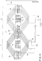
- FIG. 19 is a developed perspective view of three phases of an armature winding of a rotating electrical machine of this embodiment.
- the winding may be composed of five rows of connection rings on the connection side, which is the same number of rows as in conventional examples.
- connection ring placing space can be reduced, and the size of a rotating electrical machine can be reduced.
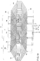
- FIG. 20 is a developed perspective view of one phase of a 2-pole 3-phase 1-parallel-circuit (no parallel circuits) armature winding as a ninth embodiment of an armature winding of a rotating electrical machine according to the invention.
- the number of slots is 66.
- the coil pitch at the connection side coil end is 26, one less than the winding pitch, and the coil pitch at the counter-connection side coil end is 27, equal to the winding pitch.
- the 2 nd upper coil piece 15a is connected to the lead-out connection conductor 21 connected to the output terminal 22, and sequentially wound to the 29 th lower coil piece, 3 rd upper coil piece, 30 th lower coil piece with the above coil pitch, and connected to the 38 th lower coil piece at the phase belt end, and then connected to the 1 st upper coil piece at the other phase end by the connection side jumper wire 20a equivalent to 11 coil pitches.
- the 28 th lower coil piece is connected to the 4 th lower coil piece of the second phase belt 18, by the lead-out connection conductor 21 connecting the phase belts.
- coil pieces are wound symmetrical to the first phase belt 17 and magnetic pole center, and the 4 th lower coil piece, 43 rd upper coil piece, and 3 rd lower coil piece are sequentially connected.
- the 34 th upper coil piece is connected to the 5 th lower coil piece by the connection side jumper wire 20a equivalent to 11 coil pitches, and the 44 th upper coil piece is connected to the neutral terminal 23 through the lead-out connection conductor 21.
- the potential difference between adjacent coil pieces As for the potential difference between adjacent coil pieces, regarding the coil pieces at the phase belt end shown in FIG. 18 , the potential of the 1 st upper coil piece is 12/22 [PU] at the connection side end, and the potential of the not-shown adjacent 66 th upper coil piece is 0 [PU]. The potential difference between the 1 st upper coil piece and 66 th upper coil piece is 0.546 [PU] considering a phase difference.
- the potential of the 11 th upper coil piece at the connection side end is 13/22 [PU]
- the not-shown adjacent 12 th upper coil piece is 1/22 [PU]. Therefore, the potential difference between the 11 th upper coil piece and 12 th upper coil piece is 0.615 [PU] considering a phase difference.
- the potential difference between coil pieces in the same phase for example the V-phase
- the potential of the 1 st upper coil piece is 12/22 [PU]
- the potential of the 2 nd upper coil piece is 1 [PU]
- the potential difference between coil pieces in the same phase is one of the above potential differences.
- a maximum potential difference between adjacent coil pieces is 0.615 [PU], which is smaller than 1.289 [PU] of conventional examples, and is very effective to prevent generation of corona discharge. Therefore, a stable armature of a rotating electrical machine can be provided.
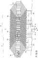
- FIG. 21 is a developed perspective view of three phases of an armature winding of a rotating electrical machine of this embodiment.
- the lead-out connection conductors 21 connected to adjacent three upper coil pieces and three lower coil pieces are closely arranged as shown by an area 21x where the lead-out connection conductors interfere with each other.
- connection conductors cause such problems as an electromagnetic force between currents flowing in the conductors, and an increase in eddy-current loss in adjacent conductors caused by currents flowing in the conductors. Further, the insulating tape wound around the conductor is deteriorated, and the insulation may become insufficient. Thus, care should be taken when determining the shape of the lead-out connection conductor 21 and when assembling the lead-out connection conductor 21.
- FIG. 22 is a developed perspective view of one phase of an armature winding as a ninth embodiment.
- FIG. 23 is a developed perspective view of three phases of the same modification.
- the 2 nd coil piece from the phase belt end is connected to the lead-out portion, as in the ninth embodiment shown in FIGS. 20 and 21 .
- the coil piece at the phase belt end in the conventional example shown in FIG. 38 is connected to the lead-out portion.
- the potential difference between adjacent coil pieces As for the potential difference between adjacent coil pieces, regarding the coil pieces at the phase belt end shown in FIG. 22 , the potential of the 1 st upper coil piece is 12/22 [PU] at the connection side end, and the potential of the not-shown adjacent 66 th upper coil piece is 10/22 [PU].
- the potential difference between the 1 st upper coil piece and 66 th upper coil piece is 0.867 [PU] considering a phase difference.
- the potential of the 11 th upper coil piece at the connection side end is 13/22 [PU]
- the not-shown adjacent 12 th upper coil piece is 0 [PU]. Therefore, the potential difference between the 11 th upper coil piece and 12 th upper coil piece is 0.591 [PU] considering a phase difference.
- a maximum potential difference between adjacent coil pieces is 0.867 [PU], the value between coil pieces of difference phases, which is increased from 0.615 [PU] of the ninth embodiment, but greatly improved from 1.289 [PU] of conventional examples.
- FIG. 24 is a developed perspective view of one phase of a modification 2 of the armature winding of the ninth embodiment.
- FIG. 25 is a developed perspective view of three phases of the same modification.
- the 2 nd coil piece from the phase belt end is connected to the lead-out portion, as in the ninth embodiment shown in FIGS. 20 and 21 , and the 4 th coil piece from the phase belt end is connected to the lead-out portion in FIGS. 24 and 25 .
- the coil piece and lead-out connection conductor 21 are closely arranged at the connection side coil end 19a, but in the above configuration, the interference between the closely arranged coil piece and connection conductor can be reduced in the modification 2.
- the potential difference between adjacent coil pieces Regard the coil pieces at the phase belt end shown in FIG. 22 , the potential of the 1 st upper coil piece is 14/22 [PU] at the connection side end, and the potential of the not-shown adjacent 66 th upper coil piece is 2/22 [PU].
- the potential difference between the 1 st upper coil piece and 66 th upper coil piece is 0.686 [PU] considering a phase difference.
- the potential of the 11 th upper coil piece at the connection side end is 15/22 [PU]
- the not-shown adjacent 12 th upper coil piece is 3/22 [PU]. Therefore, the potential difference between the 1 st upper coil piece and 66 th upper coil piece is 0.759 [PU] considering a phase difference.
- the potential difference between coil pieces in the same phase is 0.455 [PU] maximum. Therefore, in the modification 2 of the ninth embodiment, a maximum potential difference between adjacent coil pieces is 0.759 [PU], the value between coil pieces of difference phases, which is increased from 0.615 [PU] of the ninth embodiment, but greatly improved from 1.289 [PU] of conventional examples and 0.867 [PU] of the modification 1 of the ninth embodiment.
- FIG. 26 shows the relationship between the slot position X to place a coil piece connected to a lead portion and a maximum potential difference between coil pieces, in the 2-pole 3-phase 66-slot 1-parallel-circuit rotating electric machine described in the ninth embodiment.
- the white bar indicates that a lead-out connection conductor is connected to coil pieces other than those at the phase belt end, only in the first phase belt, and the hatched bar indicates that a lead-out connection conductor is connected to coil pieces other than those at the phase belt end, in both first and second phase belts.
- X ⁇ 2 indicates that as X is increased, a maximum potential difference in the corresponding armature winding is increased.
- FIG. 27 is a developed perspective view of one phase of a 2-pole 3-phase 1-parallel-circuit 66-slot armature winding as a modification 3 of the ninth embodiment.
- the coil pitch at the connection side coil end is 28, one higher than the winding pitch, and the coil pitch at the counter-connection side coil end is 27, equivalent to the winding pitch.
- coil pieces are connected in ascending numeric order in the first phase belt, but in modification 3, coil pieces are connected in descending numeric order in the first phase belt.
- the 10 th upper coil piece 15a that is second from the phase belt end close to the phase belt center is connected to the lead-out connection conductor 21 connected to the output terminal 22, and sequentially wound to the 37 th lower coil piece, 9 th upper coil piece, and 36 th lower coil piece with the above coil pitch, and connected to the 28 th lower coil piece at the phase belt end, and further connected to the 11 th upper coil piece at the other phase belt end by the connection jumper wire 20a equivalent to 11 coil pitches.
- the coil piece is connected to the 38 th lower coil piece, and the 38 th lower coil piece is connected to the 62 nd lower coil piece of the second phase belt 18 by the lead-out connection conductor 21 connecting the phase belts.
- coil pieces are wound symmetrical to the first phase belt 17 and magnetic pole center, and sequentially connected to the 62 nd lower coil piece, 35 th upper coil piece, and 63 rd lower coil piece.
- the 44 th upper coil piece is connected to the 61 st lower coil piece by the connection side jumper wire 20a equivalent to 11 coil pitches, and the 34 th upper coil piece is connected to the neutral terminal 23 through the lead-out connection conductor 21.
- the potential difference between adjacent coil pieces As for the potential difference between adjacent coil pieces, regarding the coil pieces at the phase belt end shown in FIG. 27 , the potential of the 1 st upper coil piece is 13/22 [PU] at the connection side end, and the potential of the not-shown adjacent 66 th upper coil piece is 1/22 [PU]. The potential difference between the 1 st upper coil piece and 66 th upper coil piece is 0.615 [PU] considering a phase difference.
- the potential of the 11 th upper coil piece at the connection side end is 12/22 [PU], and that of the not-shown adjacent 12 th upper coil piece is 0 [PU]. Therefore, the potential difference between the 11 th upper coil piece and 12 th upper coil piece is 0.546 [PU] considering a phase difference.
- the potential of the 5 th lower coil piece at the connection side end is 2/22 [PU]
- the adjacent not-shown 6 th lower coil piece is 13/22 [PU]. Therefore, the potential difference between the 1 st upper coil piece and 66 th upper coil piece is 0.641 [PU] considering a phase difference.
- the potential difference between coil pieces in the same phase is one of 0.455 [PU] and 0.045 [PU].
- a maximum potential difference between adjacent coil pieces is 0.641 [PU]
- the value between coils of different phases which is smaller than 1.289 [PU] of conventional examples. Therefore corona discharge can be prevented, and a stable armature of a rotating electrical machine can be provided.
- This modification is characterized in that a maximum potential difference between coil pieces appears in the lower coils.
- FIG. 28 is a developed perspective view of one phase of a 2-pole 3-phase 1-parallel-circuit (no parallel circuits) armature winding as a tenth embodiment of an armature winding of a rotating electrical machine according to the invention.
- the number of slots is 66.
- the coil pitch at the connection side coil end is 27, equivalent to the winding pitch, and the coil pitch at the counter-connection side coil end is 26, one less than the winding pitch.
- the 10 th upper coil piece 15a that is second from the end close to the center of a phase belt is connected to the lead-out connection conductor 21 connected to the output terminal 22, and sequentially wound to the 36 th lower coil piece, 9 th upper coil piece, and 35 th lower coil piece with the above coil pitch, and connected to the 1 st upper coil piece at the phase belt end, and then connected to the 38 th lower coil piece at the other phase end by the counter-connection side jumper wire 20b equivalent to 11 coil pitches.
- the coil piece is connected to the 11 th upper coil piece, and 37 th lower coil piece.
- the 37 th lower coil piece is connected to the 62 nd lower coil piece of the second phase belt 18 by the lead-out connection conductor 21 connecting the phase belts.
- the coil pieces are wound symmetrical to the first phase belt 17 and magnetic pole center, and the 62 nd lower coil piece, 36 th upper coil piece, and 63 rd lower coil piece are sequentially connected.
- the 5 th lower coil piece is connected to the 34 th upper coil piece by the counter-connection side jumper wire 20b equivalent to 11 coil pitches, and connected to the 61 st lower coil piece and 35 th upper coil piece, and the 35 th upper coil piece is connected to the neutral terminal 23 through the lead-out connection conductor 21.
- the potential difference between adjacent coil pieces As for the potential difference between adjacent coil pieces, regarding the coil pieces at the phase belt end shown in FIG. 28 , the potential of the first upper coil piece is 13/22 [PU] at the connection side end, and the potential of the not-shown adjacent 66 th upper coil piece is 2/22 [PU]. The potential difference between the 1 st upper coil piece and 66 th upper coil piece is 0.642 [PU] considering a phase difference.
- the potential of the 5 th lower coil piece at the connection side end is 2/22 [PU]
- the not-shown adjacent 6 th lower coil piece is 13/22 [PU]. Therefore, the potential difference between the 5 th lower coil piece and 6 th lower coil piece is 0.642 [PU] considering a phase difference, which is a maximum potential difference between coil pieces in this embodiment.
- a maximum potential difference between adjacent coils is 0.642 [PU], the value between coil pieces of different phases, which is smaller than 1.289 [PU] of conventional examples.
- the number of connection rings in a connecting part can be decreased, and the interference between the connection conductors in the lead-out portion can be reduced.
- FIG. 29 is a developed perspective view of one phase of a 2-pole 3-phase 1-parallel-circuit 66-slot armature winding as a modification of the tenth embodiment.
- the number of slots is 66.
- the coil pitch at the connection side coil end is 27, equivalent to the winding pitch, and the coil pitch at the counter-connection side coil end is 28, one larger than the winding pitch.
- the 2 nd upper coil piece 15a that is second from the phase belt end is connected to the lead-out connection conductor 21 connected to the output terminal 22, and sequentially wound to the 29 th lower coil piece, 3 rd upper coil piece, and 30 th lower coil piece with the above coil pitch, and connected to the 11 th upper coil piece at the phase belt end, and further connected to the 28 th lower coil piece at the other phase end by the counter-connection side jumper wire 20b equivalent to 11 coil pitches. Then, the coil piece is connected to the 1 st upper coil piece and 29 th lower coil piece.
- the 29 th lower coil piece is connected to the 4 th lower coil piece of the second phase belt 18 by the lead-out connection conductor 21 connecting the phase belts.
- the coil pieces are wound symmetrical to the first phase belt 17 and magnetic pole center, and the 4 th lower coil piece, 42 nd upper coil piece, and 3 rd lower coil piece are sequentially connected.
- the 61 st lower coil piece is connected to the 44 th upper coil piece by the counter-connection side jumper wire 20b equivalent to 11 coil pitches, and connected to the 5 th lower coil piece and 43 rd upper coil piece, and the 43 rd upper coil piece is connected to the neutral terminal 23 through the lead-out connection conductor 21.
- the potential difference between adjacent coil pieces Regard the coil pieces at the phase belt end shown in FIG. 29 , the potential of the 11 th upper coil piece is 13/22 [PU] at the connection side end, and the potential of the not-shown adjacent 12 th upper coil piece is 2/22 [PU].
- the potential difference between the 1 st upper coil piece and 66 th upper coil piece is 0.642 [PU] considering a phase difference.
- the potential of the 38 th lower coil piece at the connection side end is 13/22 [PU]
- the potential of the not-shown adjacent 39 th lower coil piece is 2/22 [PU]. Therefore, the potential difference between the 5 th lower coil piece and 6 th lower coil piece is 0.642 [PU] considering a phase difference, which is a maximum potential difference between coil pieces in this embodiment.
- a maximum potential difference between adjacent coils is 0.642 [PU], the value between coil pieces of different phases, which is smaller than 1.289 [PU] of conventional examples.
- the number of connection rings in the connecting part can be decreased, and the interference between the connection conductors in a lead-out portion can be reduced. Therefore, it is possible to prevent generation of corona discharge, and solve such problems as an electromagnetic force between currents flowing in the conductors, an increase in eddy-current loss in adjacent conductors caused by currents flowing in the conductors, and poor insulation caused by deteriorated insulating tape wound around the conductor. Therefore, a reliable armature of a rotating electrical machine can be provided.
- FIG. 30 is a developed perspective view of one phase of a 2-pole 3-phase 1-parallel-circuit (no parallel circuits) armature winding as an eleventh embodiment of an armature winding of a rotating electrical machine according to the invention.
- the number of slots is 66.
- the coil pitch at the connection side coil end is 25, two less than the winding pitch, and the coil pitch at the counter-connection side coil end is 27, equal to the winging pitch.
- the 2 nd upper coil piece 15a is connected to the lead-out connection conductor 21 connected to the output terminal 22, and sequentially wound to the 29 th lower coil piece, 4 th upper coil piece, and 31 st lower coil piece with the above coil pitch, and connected to the 37 th lower coil piece at the phase belt end, and further connected to the 1 st upper coil piece at the other phase end by the connection side jumper wire 20a equivalent to 11 coil pitches.
- the coil piece is connected to the 28 th lower coil piece, and sequentially wound to the 28 th lower coil piece, 3 rd upper coil piece, and 30 th lower coil piece with the above coil pitch.
- the 38 th lower coil piece is connected to the 4 th lower coil piece of the second phase belt 18 by the lead-out connection conductor 21 connecting the phase belts.
- coil pieces are wound symmetrical to the first phase belt 17 and magnetic pole center, and the 4 th lower coil piece, 43 rd upper coil piece, and 2 nd lower coil piece are sequentially connected.
- the 35 th upper coil piece is connected to the 5 th lower coil piece by the connection side jumper wire 20a equivalent to 11 coil pitches, and sequentially connected to the 44 th upper coil piece, 3 rd lower coil piece, 42 nd upper coil piece, and 1 st lower coil piece, and the 34 th upper coil piece is connected to the neutral terminal 23 through the lead-out connection conductor 21.
- the potential difference between adjacent coil pieces As for the potential difference between adjacent coil pieces, regarding the coil pieces at the phase belt end shown in FIG. 30 , the potential of the first upper coil piece is 17/22 [PU] at the connection side end, and the potential of the not-shown adjacent 66 th upper coil piece is 5/22 [PU].
- the potential difference between the 1 st upper coil piece and 66 th upper coil piece is 0.908 [PU] considering a phase difference, which is a maximum potential difference in this embodiment.
- the potential difference is not increased to larger than this value, and the value can be decreased to lower than those in the above examples, as a maximum potential difference between the same-phase coil pieces.
- a maximum potential difference between adjacent coils is 0.908 [PU], the value between coil pieces of different phases, which is smaller than 1.289 [PU] of conventional examples. Therefore, generation of corona discharge can be prevented, and a stable armature winding of a rotating electrical machine can be provided.
- X is set to meet 3 ⁇ X ⁇ N t2 , assuming that the number of slots per one phase belt is N t , N t2 is a minimum integer not smaller than N t /2, and a coil piece connected to a lead-out portion is the x-the coil piece counted from the phase belt end close to the magnetic pole center.
- FIG. 31 is a developed perspective view of one phase of a 2-pole 3-phase armature winding as a twelfth embodiment of an armature winding of a rotating electrical machine according to the invention, which is improved from the armature winding of the rotating electrical machine mentioned in the conventional example 3.
- the number of slots is 72, three parallel circuits are provided, and the number of slots occupied by each of the upper and lower coil pieces per one phase is 12.
- the armature winding comprises three parallel circuits, 1 to 3, indicated by three kinds of line.
- the parallel circuits of twelve upper coil pieces 15a and lower coil pieces 16a consisting a first phase belt 17 are numbered 1, 2, 3, 1, 2, 3, 1, 2, 3, 1, 2, 3 sequentially from the left side.
- the parallel circuits of twelve upper coil pieces 15b and lower coil pieces 16b consisting a second phase belt are numbered 3, 2, 1, 3, 2, 1, 3, 2, 1, 3, 2, 1, 3, 2, 1 sequentially from the left side.
- the lead-out connection conductor 21 is connected to the second and third upper coil pieces close to the end of the phase belt in circuits 2 and 3, but the fourth upper coil piece is connected to the lead-out connection conductor 21 in circuit 1.
- the 4 th upper coil piece is sequentially connected to the 34 th lower coil piece, 7 th upper coil piece, 37 th lower coil, 10 th upper coil piece, and 40 th lower coil piece.
- the 40 th lower coil is connected to the 1 st upper coil piece by the connection side jumper wire 20a.
- the connection conductor 21 connecting phase belts connected to the 31 st lower coil piece is connected to the 3 rd lower coil piece in the second phase belt.
- the 3 rd lower coil piece, 45 th upper coil piece, 72 nd lower coil piece, 42 nd upper coil piece, 69 th lower coil piece, and 39 th upper coil piece are sequentially connected.
- the 39 th upper coil piece is connected to the 6 th lower coil piece by the connection side jumper wire 20a, and the connection conductor 21 connecting phase belts connected to the 36 th lower coil piece is connected to the neutral terminal 23.
- the above values are a maximum potential difference between coil pieces in this embodiment, which is reduced to about half of the maximum potential difference of 1.231 [PU] in the conventional example 3.
- FIG. 32 is a developed perspective view of one phase of a 2-pole 3-phase armature winding as a thirteenth embodiment of an armature winding of a rotating electrical machine according to the invention, which is improved from the armature winding of the rotating electrical machine described in conventional example 4.
- the number of slots is 72, three parallel circuits are provided, and the number of slots occupied by each of the upper and lower coil pieces per one phase is 12.
- the armature winding comprises three parallel circuits, 1 to 3, indicated by three kinds of line.
- the parallel circuits of twelve upper coil pieces 15a and lower coil pieces 16a forming a first phase belt 17 are numbered 1, 2, 1, 1, 2, 1, 1, 2, 1, 1, 2, 1 sequentially from the left side.
- the parallel circuits of twelve upper coil pieces 15b and lower coil pieces 16b consisting a second phase belt are numbered 3, 2, 3, 3, 2, 3, 3, 2, 3, 3, 2, 3 sequentially from the left side.
- coil pieces are connected as in the conventional example 4, and the lead-out ends of the first phase 17 and second phase 18 are connected by the lead-out connection conductor 21.
- the 3 rd upper coil piece is connected to the lead-out connection conductor 21.
- the 3 rd upper coil piece is sequentially connected to the 33 rd lower coil piece, 6 th upper coil piece, 36 th lower coil piece, 9 th upper coil piece, 39 th lower coil piece, and 12 th upper coil piece.
- the 42 nd lower coil piece is connected to the 1 st upper coil piece by the connection side jumper wire 20a, and further connected to the 31 st lower coil piece, and sequentially connected to the 4 th upper coil piece, 34 th lower coil piece, 7 th upper coil piece, 37 th lower coil piece, 10 th upper coil piece, and 40 th lower coil piece.
- the 40 th lower coil piece is connected to the neutral terminal 23 by the connection conductor 21 connecting the phase belts.
- coil pieces are connected as in the circuit 1, and the 4 th lower coil piece is connected to the lead-out connection conductor 21.
- the 4 th lower coil piece is sequentially connected to the 46 th upper coil piece, 1 st lower coil piece, 43 rd upper coil piece, 70 th lower coil piece, 40 th upper coil piece, and 67 th lower coil piece.
- the 37 th upper coil piece is connected to the 6 th lower coil piece by the connection side jumper wire 20a, and further connected to the 48 th upper coil piece, and sequentially connected to the 3 rd lower coil piece, 45 th upper coil piece, 72 nd lower coil piece, 42 nd upper coil piece, 69 th lower coil piece, and 39 th upper coil piece.
- the 39 th upper coil piece is connected to the neutral terminal 23 by the connection conductor 21 connecting the phase belts.
- the potential difference between adjacent coil pieces regarding the coil pieces at the phase belt end shown in FIG. 32 , the potential of the 12 th upper coil piece is 5/8 [PU] at the connection side end, and the potential of the not-shown adjacent 13 th upper coil piece is 4/8 [PU].
- the potential difference between the 12 th upper coil piece and 13 th upper coil piece is 0.976 [PU].
- the potential of the 42 nd lower coil piece is 4/8 [PU] at the connection side end, and the potential of the not-shown adjacent 43 rd lower coil piece is 5/8 [PU]. Therefore, the potential difference between the 42 nd lower coil piece and 43 rd lower coil piece is the same 0.976 [PU].
- the above values are a maximum potential difference between coil pieces in this embodiment, which is greatly reduced from the maximum potential difference of 1.625 [PU] of the conventional example 4.
- the invention is not limited to the embodiments described herein and shown in the drawings.
- the invention may be embodied in various other forms without departing from the essential characteristics.
- the embodiments may be appropriately combined. In such a case, the effects of combination may be obtained.
- the embodiments described herein include various steps of the invention, and the invention may be extracted in various combined forms of the constituent elements disclosed herein. For example, when the invention is extracted by omitting some constituent element from all elements disclosed in the embodiments, the omitted parts may be appropriately compensated by well-known common techniques when the extracted invention is embodied.
- the winding and armature core can be effectively cooled by air.
Description
- The invention relates to an armature winding of a rotating electrical machine, which is configured to prevent generation of corona discharge by reducing a potential difference between adjacent coil pieces.
- A conventional armature winding of a rotating electrical machine has a structure shown in
FIG. 33 . -
FIG. 33 is a sectional view showing an example of an armature winding placed in a slot of an armature core of a rotating electrical machine. - In
FIG. 33 , areference number 12 denotes an armature core formed by stacking a laminated iron plate. An armature winding 14 is housed in aslot 13 provided in the circumference of thearmature core 12. - The armature winding 14 is provided in two layers of
upper coil pieces 15 close to the slot opening, andlower coil pieces 16 close to the slot bottom, and the outer circumference is covered by a maininsulating layer 24. - An
insulating plate 10a is provided at the slot bottom, and aninsulating partition plate 10b is provided between theupper coil piece 15 andlower coil piece 16. Awedge 9 is inserted into the slot opening through aninsulating plate 10c. - In a large-capacity rotating electrical machine, the machine capacity is increased by increasing a generated voltage by connecting the upper and
lower coil pieces - As a voltage of the armature winding 14 is increased, the thickness of the main insulating
layer 24 of the armature winding is increased to withstand the voltage. As a result, a cross section of a conductor is decreased, a current density is increased, and a loss is increased. Thus, the armature winding is divided into multiple parallel circuits, the armature winding voltage is decreased without changing the machine capacity, and the thickness of the main insulatinglayer 24 is decreased, thereby decreasing the loss and increasing the cooling capacity. - First, a first example of a conventional armature winding is described.
-
FIG. 34 is a developed perspective view of one phase of a 2-pole 3-phase 66-slot armature winding having two parallel circuits.FIG. 35 is a developed perspective view of three phases of the same armature winding shown inFIG. 34 . The other two phases not shown inFIG. 34 are obtained by displacing the configuration of the shown armature winding by 120° and 240°, respectively. - As shown in
FIG. 34 , in the armature winding 14, eleven slots are occupied by each of the upper and lower coil pieces per one phase belt. - The phase belt mentioned here means a part of a winding, which forms one same phase by dividing each of three phases into multiple parts, housing upper and lower coil pieces in two layers in multiple slots of an assigned laminated iron core (an armature core), and sequentially connecting them in series.
- As shown in
FIG. 34 , the armature winding 14 of each phase has the upper coil piece 15 (15a, 15b) housed in a slot close to an opening, and the lower coil piece (16a, 16b) housed in a slot close to a bottom. The ends of the upper andlower coil pieces side coil end 19a connected to a lead-out portion of the winding, and at a counter-connectionside coil end 19b that is axially opposite and not connected to a lead-out portion of the winding. - Further, the armature winding 14 has a
first phase belt 17, in which each of the upper andlower coil pieces armature core 12, and asecond phase belt 18, in which each of the upper andlower coil pieces - The armature winding 14 of each phase has two parallel circuits, which are indicated by a solid line and a broken line.
- In the first and
second phase belts upper coil piece 15 is connected to the correspondinglower coil piece 16 separated by a fixed pitch, at the connection side and counter-connectionside coil ends connection conductor 21 provided at the connectionside coil end 19a, thereby forming the armature winding 14. - In
FIG. 34 , on the counter-connection side, an upper coil piece placed in the 1st slot (the 1st upper coil piece) is connected to a lower coil piece placed in the 28th slot (the 28th lower coil piece), and a coil pitch is 27. On the counter-connection side, an upper coil piece placed in the 11th slot (the 11th upper coil piece) is connected to a lower coil piece placed in the 37th slot (the 37th lower coil piece), and a coil pitch is 26. - In the armature winding shown in
FIG. 34 , a winding pitch means a pitch between theslot 13 housing theupper coil piece 15a of thefirst phase belt 17 and theslot 13 housing lower coil pieces, for example, and the winding pitch inFIG. 34 is 27. In other words, the upper and lower coil pieces are connected to have a coil pitch one less than a winding pitch at the connection side coil end, and a coil pitch equal to a winding pitch at the counter-connection side coil end. - When the number of parallel circuits of each phase belt is less than the number of poles, as seen in Patent document 1 (
FIG. 2 ), for example, a lead-out portion is usually provided at the end of a phase belt, and a conductor of the lead-out portion is connected to a coil piece at the phase belt end. For example, inFIG. 34 , at the connectionside coil end 19a of thefirst phase belt 17, the lead-outconnection conductor 21 connected to theoutput terminal 22 is connected to the 1st coil piece of theupper coil piece 15a, and the 38th coil piece of thelower coil piece 16a is connected to the lead-outconnection conductor 21, and further connected to aneutral terminal 23. - In the
second phase belt 18, at the connectionside coil end 19a, the lead-outconnection conductor 21 connected to theoutput terminal 22 is connected to the 5th coil piece of thelower coil piece 16a, and the 34th coil piece of theupper coil piece 15b is connected to the lead-outconnection conductor 21, and further connected to theneutral terminal 23. - In the following description, the centers of magnetic pole Pa and Pb are defined as shown in
FIG. 34 , and in the first phase belt, the 1st upper coil piece is called an upper coil piece positioned at the phase belt end far from the magnetic pole center, and the 11th upper coil piece is called an upper coil piece positioned at the phase belt end close to the magnetic pole center. Concerning the lower coil piece, the 28th lower coil piece is called a lower coil piece positioned at the phase belt end close to the magnetic pole center, and the 38th lower coil piece is called a lower coil piece positioned at the phase belt end far from the magnetic pole center. - Therefore, in normal connection, the first upper coil piece that is an upper coil piece positioned at the phase belt end far from the magnetic pole center is connected to the 28th lower coil piece that is a lower coil piece positioned at the phase belt end close to the magnetic pole center.
- In the armature winding 14, coil pieces are sequentially wound from the left side to right side in
FIG. 34 , namely from the 1st upper coil piece to 28th lower coil piece, 2nd upper coil piece, and 29th lower coil piece. Hereinafter, this will be described as coil pieces wound so that upper coil pieces are positioned close to the magnetic pole center. - Similarly, in the second phase belt, the 5th lower coil piece, 4th upper coil piece, 4th lower coil piece, and 43rd upper coil piece coil pieces are wound so that lower coil pieces are positioned close to the magnetic pole center.
- In the following description, a phase comprising the 1st to 11th upper coil pieces is called a V-phase, a phase comprising the 12th to 22nd upper coil pieces is called a U-phase, and a phase comprising the 23rd to 33rd upper coil pieces is called a W-phase. This will be repeated in the following coil pieces. It is of course no problem if the configuration and sequence of the V, U and W phases are changed.
- Next, a potential difference between adjacent coil pieces is explained. Here, the potential difference is indicated by p.u. as a ratio to an induced voltage in one phase.
- Regarding the coil pieces at the phase belt end in
FIG. 35 , the potential of the upper coil piece placed in the 23rd slot (the 23rd upper coil piece) at the connection side end is 1[PU], and the potential of the upper coil piece placed in the adjacent 22nd slot (the 22nd upper coil piece) is 10/11 [PU]. -
FIG. 36 shows a vector indicating an example of the potential difference between the adjacent coil pieces inFIG. 35 . The potential difference between the 23rd upper coil piece and 22nd upper coil piece is 1.654 [PU] considering a phase difference. - On the other hand, as the upper coil piece placed in the 12th slot (the 12th upper coil piece) is connected to the
neutral terminal 23, the potential of the 12th upper coil piece at the connection side end is 0 [PU] at the connection side end, and the potential of the upper coil piece placed in the adjacent 11th slot is 1/11 [PU]. As indicated by the vector inFIG. 36 , the potential difference between the 12th upper coil piece and 11th upper coil piece is 1/11 = 0.091 [PU]. - On the other hand, between coil pieces of the same phase, the potential difference between any coil pieces is 1/11 = 0-091 [PU].
-
FIG. 37 shows the potential differences between adjacent coil pieces, particularly upper coil pieces, at the connection side coil end obtained as described above. The phases shown in legends indicate the phases of coil pieces to which smaller numbers are given. - As shown in
FIG. 37 , in the above-described 2-pole 3-phase 66-slot armature winding having two parallel circuits, a maximum potential difference between adjacent coil pieces is 1.654 [PU] in the boundary of phase belts. - Next, a second example of a conventional armature winding is explained.
-
FIG. 38 is a developed perspective view of one phase of a 2-pole 3-phase 66-slot armature winding having one parallel circuit. The number of slots occupied by each of the upper and lower coil pieces per one phase belt is 11, as in the armature winding shown inFIG. 34 . - In
FIG. 38 , the winding pitch is 27, which is the same as thecoil pitch 27 at the counter-connectionside coil end 19b, and thecoil pitch 26 at the connectionside coil end 19a is one less than the winding pitch. - In
FIG. 38 , as inFIG. 34 , a coil piece at the phase belt end is connected to a lead-out connection conductor. For example, inFIG. 34 , at the connectionside coil end 19a of thefirst phase belt 17, the 1st coil piece of theupper coil piece 15a is connected to the lead-outconnection conductor 21, and further connected to theoutput terminal 22, and at the connectionside coil end 19a of thesecond phase belt 18, the 34th coil piece of theupper coil piece 15b is connected to the lead-outconnection conductor 21, and further connected to theneutral terminal 23. - The 38th coil piece of the
lower coil piece 16a in thefirst phase belt 17 and the 5th coil piece of thelower coil piece 16b in thesecond phase belt 18 are connected by a connectionside jumper wire 20a. - Next, the potential difference between adjacent coil pieces will be explained. For example, regarding the coil pieces at the phase belt end in
FIG. 38 , the potential of the 44th upper coil piece at the connection side end is 10/22 [PU], and the potential of the not- shown adjacent 45th upper coil piece is 1 [PU]. The potential difference between the 44th upper coil piece and 45th upper coil piece is 1.289 [PU] considering a phase difference of 120°. -
FIG. 39 shows a potential difference between adjacent coil pieces at a connection side coil end. In the second example of a conventional armature winding, a maximum potential difference between adjacent coil pieces is 1.289 [PU] in the boundary of phase belts. - Next, a third example of a conventional armature winding is explained.
- In a large-capacity rotating electrical machine using an indirect cooling system, in particular, it is common to increase a cooling cycle of an armature winding by increasing the number of slots in an armature core. Thus, an armature winding having three or more parallel circuits is required. When the number of parallel circuits is more than the number of poles, as in a 2-pole 3-parallel-circuit armature winding, it is impossible to completely equate the voltage generated in each parallel circuit, and a circulation current is generated between the parallel circuits, increasing a loss in the armature winding.
- To decrease a loss caused by a circulation current, it is necessary to minimize the imbalance in the voltages generated in the parallel circuits. Therefore, it is necessary to take special care in the arrangement of coil pieces in each parallel circuit in each phase belt.
-
FIG. 40 is a developed perspective view of one phase of an armature winding described inPatent document 4. This is a 2-pole 3-phase armature winding having 72 slots in an armature core. The number of slots per one phase belt occupied by each of the upper and lower coil pieces is 12. - The armature winding comprises three parallel circuits, 1 to 3, indicated by three kinds of line in
FIG. 40 . The parallel circuits of twelveupper coil pieces 15a andlower coil pieces 16a, constituting afirst phase belt 17, are numbered 1, 2, 3, 1, 2, 3, 1, 2, 3, 1, 2, 3 sequentially from the left side, and similarly, the parallel circuits of twelveupper coil pieces 15b andlower coil pieces 16b, consisting a second phase belt, are numbered 3, 2, 1, 3, 2, 1, 3, 2, 1, 3, 2, 1 sequentially from the left side, thereby decreasing a voltage deviation (an absolute value of deviation from an average phase voltage) in the parallel circuits and a phase deviation (a phase angle deviation from an average phase voltage) in the parallel circuits. - To realize the above connection, in the armature winding 14 shown in
FIG. 40 , the lead-out ends of the parallel circuits of the first andsecond phase belts out connection conductor 21. - The potential difference between adjacent coil pieces is 1.231 [PU] at maximum in the boundary of the phase belts, between the 1st upper coil piece and not-shown 72nd upper coil piece, for example.
- Next, a fourth example of a conventional armature winding is explained.
-
Patent document 5 describes an improvement to simplify the structure of an armature winding of a rotating electrical machine shown in the third example. -
FIG. 41 is a developed perspective view of one phase of an armature winding improved by the method described inpatent document 5. This is a 2-pole 3-phase armature winding having 72 slots in an armature core. The number of slots per one phase belt occupied by each of the upper and lower coil pieces is 12. - The armature winding comprises three parallel circuits, 1 to 3, indicated by three kinds of line in
FIG. 40 . The parallel circuits of twelveupper coil pieces 15a andlower coil pieces 16a, consisting afirst phase belt 17, are numbered 1, 2, 1, 1, 2, 1, 1, 2, 1, 1, 2, 1 sequentially from the left side. Similarly, the parallel circuits of twelveupper coil pieces 15b andlower coil pieces 16b, consisting asecond phase belt 18, are numbered 3, 2, 3, 3, 2, 3, 3, 2, 3, 3, 2, 3 sequentially from the left side. Theparallel circuit 3 of the first phase belt andparallel circuit 1 of the second phase belt, which are electrically equivalent, are interchanged so that theparallel circuits - To realize the above connection, in the armature winding 14 shown in
FIG. 41 , the connection side lead-outend 19a is expanded by a 2-phase jumper wire 20a, and the lead-out terminals of the parallel circuits of the first andsecond phase belts out connection conductor 21. - The potential difference between adjacent coil pieces is 1.625 [PU] at maximum in the boundary of the phase belts, between the 1st upper coil piece and not-shown 72nd upper coil piece, for example.
- When the voltage of the armature winding is increased, the potential difference between adjacent coil pieces is increased. Particularly, in the above-described example of a conventional armature winding, the potential difference between adjacent coil pieces in the boundary of phase belts is increased, and corona discharge may occur during operation at the coil end in the boundary of phase belts.
- Especially, in a rotating electrical machine using an indirect cooling system to cool an armature winding from the outside of a main insulating layer, when non-pressurized air is used as a coolant, corona discharge is more likely to occur than when using hydrogen as the coolant, the insulation is deteriorated, and the operation of a rotating electrical machine may become unstable. This becomes a problem when increasing the voltage and capacity of a rotating electrical machine.
- In an ideal state, corona discharge occurs in an electric field of about 3kV/mm in air at a room temperature and atmospheric pressure, but actually, corona discharge may occur in a lower electric field, depending on the surface conditions of a charged material.
- To prevent corona discharge between coil pieces in the boundary of phase belts,
patent document 1 improves corona resistance by winding a mica tape or sheet around a coil end, or the outside of a corona prevention layer. - Further, even if electric discharge occurs between coil ends, the corona resistant mica prevents corona discharge caused by the electric discharge, or decreases the insulation damage.
- The invention described in the
patent document 1 decreases the insulation damage without changing the coil shape, whereas a tape or sheet is further wound around the outside of an insulated coil. This deteriorates heat transfer in the insulating material, and coil cooling effect, causing localized overheating. Further, the size, including the insulating material, is increased, the maintenance workability is lowered, and the armature may be accidentally damaged by maintenance. - In
patent document 2, two kinds of coil groups with different directions of induced magnetic flux are prepared and combined to decrease a potential difference between coil pieces. - However, in the configuration described in
patent document 2, the coil end structure is restricted, and the coil group structure is complicated. The configuration is not suitable for a large-capacity rotating electrical machine such as a large turbine generator for thermal power generation. - Further,
patent document 3 describes a 3-phase 4-pole 72-slot armature winding having three parallel circuits, in which coil pieces other than those at the ends of a phase belt are connected to a lead-out portion, and the voltage imbalance between the parallel circuits is reduced, and the potential difference between adjacent coils in the other phase is decreased on the connection side. - However,
patent document 3 aims at reducing the voltage imbalance between parallel circuits, and describes a winding method with specific numbers of poles, slots and parallel circuits. It does not decrease the potential difference from the coil pieces of the adjacent other phase, while keeping the same state as in conventional examples with respect to the voltage imbalance between parallel circuits. - It is possible to provide a larger space between coil pieces to increase the distance between the coil pieces of different phases at a coil end. However, this increases the size of a rotating electrical machine, increases the amount of material, and the increased weight restricts transportation and installation of the machine. It is also possible to provide a larger space between coil pieces by deforming a coil end after assembling. However, this may damage the insulation when deforming the coils, generates an unbalanced electromagnetic force, causing a problem in the reliability of a rotating electrical machine.
- It is necessary to increase a line current or a terminal voltage to increase the capacity of a rotating electrical machine. A line current is restricted by a temperature increase, and the size and weight of a coil doctor. Therefore, it is necessary to increase a terminal voltage. For this purpose, it is necessary to restrict corona discharge of an armature winding as described above.
-
- Patent document 1:
U.S. Patent Application Publication No. 2007/0170804 - Patent document 2:
U.S. Patent No. 4341970 - Patent document 3: Japanese Patent No.
3578939 - Patent document 4:
U.S. Patent No. 3152273 - Patent document 5:
U.S. Patent No. 3660705 -
US 4 404 486 A - It is an object of the invention to provide a highly reliable armature winding of a rotating electrical machine, which is configured to prevent generation of corona discharge by reducing a potential difference between adjacent coil pieces, without increasing the dimensions of an insulator at a coil end.
- According to the present invention the above object is achieved by a 3-phase 2-layer armature winding for a rotating electrical machine according to
claim 1. The dependent claims are directed to different advantageous aspects of the invention which is set forth inindependent claim 1. Merelyfigure 1 represents embodiments of the presently claimed invention. All other embodiments are shown for illustrative purposes only. In the following, the words "example" and "embodiment" or "embodiment of the invention" are used to designate actual embodiments of the claimed invention only with reference tofigure 1 ; other occurrences of said words refer to examples shown for illustrative purposes only. - According to the invention, it is possible to improve reliability by reducing a potential difference between adjacent coil pieces, and prevent generation of corona discharge, without increasing the dimensions of an insulator at a coil end.
-
-
FIG. 1 is a developed perspective view of one phase of a first embodiment of an armature winding of a rotating electrical machine according to the invention; -
FIG. 2 is a developed perspective view of three phases of the same embodiment; -
FIG. 3 shows a vector indicating a potential difference between adjacent coil pieces in the same embodiment; -
FIG. 4 is a graph showing the distribution of potential differences between adjacent coil pieces in the same embodiment; -
FIG. 5 is a developed perspective view of one phase of a modification of the first embodiment; -
FIG. 6 is a developed perspective view of three phases of a modification of the armature winding in the same embodiment; -
FIG. 7 is a graph showing the distribution of potential differences between adjacent coil pieces in the same modification; -
FIG. 8 is a graph showing the relationship between a slot position to place a coil piece connected to a lead-out portion and a maximum potential difference between coils in a first embodiment of the invention; -
FIG. 9 is a developed perspective view of one phase of a second embodiment of an armature winding of a rotating electrical machine according to the invention; -
FIG. 10 is a developed perspective view of one phase of a third embodiment of an armature winding of a rotating electrical machine according to the invention; -
FIG. 11 is a developed perspective view of one phase of a 2-pole 3-phase 2-parallel-circuit armature winding, as a fourth embodiment of an armature winding of a rotating electrical machine according to the invention; -
FIG. 12 is a developed perspective view of three phases of the same embodiment; -
FIG. 13 is a developed perspective view of one phase of a modification of the fourth embodiment; -
FIG. 14 is a developed perspective view of one phase of a 2-pole 3-phase 2-parallel-circuit armature winding, as a fifth embodiment of an armature winding of a rotating electrical machine according to the invention; -
FIG. 15 is a developed perspective view of one phase of a 2-pole 3-phase 2-parallel-circuit armature winding, as a sixth embodiment of an armature winding of a rotating electrical machine according to the invention; -
FIG. 16 is a developed perspective view of one phase of a 2-pole 3-phase 2-parallel-circuit armature winding, as a seventh embodiment of an armature winding of a rotating electrical machine according to the invention; -
FIG. 17 is a developed perspective view of three phases of the same embodiment; -
FIG. 18 is a developed perspective view of one phase of a 2-pole 3-phase 2-parallel-circuit armature winding, as an eighth embodiment of an armature winding of a rotating electrical machine according to the invention; -
FIG. 19 is a developed perspective view of three phases of the same embodiment; -
FIG. 20 is a developed perspective view of one phase of a 2-pole 3-phase 1-parallel-circuit armature winding, as a ninth embodiment of an armature winding of a rotating electrical machine according to the invention; -
FIG. 21 is a developed perspective view of three phases of the same embodiment; -
FIG. 22 is a developed perspective view of one phase of amodification 1 of the armature winding in the ninth embodiment; -
FIG. 23 is a developed perspective view of three phases of thesame modification 1; -
FIG. 24 is a developed perspective view of one phase of amodification 2 of the armature winding in the ninth embodiment; -
FIG. 25 is a developed perspective view of three phases of thesame modification 2; -
FIG. 26 is a graph showing the relationship between a slot position to place a coil piece connected to a lead-out portion and a maximum potential difference between coils in the rotating electrical machine of the ninth embodiment; -
FIG. 27 is a developed perspective view of one phase of athird modification 3 of the armature winding in the ninth embodiment; -
FIG. 28 is a developed perspective view of one phase of a 2-pole 3-phase 1-parallel-circuit armature winding, as a tenth embodiment of an armature winding of a rotating electrical machine according to the invention; -
FIG. 29 is a developed perspective view of one phase of a modification of the armature winding in the tenth embodiment; -
FIG. 30 is a developed perspective view of one phase of a 2-pole 3-phase 1-parallel-circuit armature winding, as an eleventh embodiment of an armature winding of a rotating electrical machine according to the invention; -
FIG. 31 is a developed perspective view of one phase of a 2-pole 3-phase armature winding, as a twelfth embodiment of an armature winding of a rotating electrical machine according to the invention; -
FIG. 32 is a developed perspective view of one phase of a 2-pole 3-phase armature winding, as a thirteenth embodiment of an armature winding of a rotating electrical machine according to the invention; -
FIG. 33 is a sectional view of a slot of an armature of a rotating electrical machine; -
FIG. 34 is a perspective view of one phase of a first example of an armature winding of a conventional rotating electrical machine; -
FIG. 35 is a perspective view of three phases of the first example; -
FIG. 36 shows a vector indicating a potential difference between adjacent coil pieces in the first example; -
FIG. 37 is a graph showing a distribution of a potential difference between adjacent coil pieces in the first example; -
FIG. 38 is a perspective view of one phase of a second example of an armature winding of a conventional rotating electrical machine; -
FIG. 39 is a graph showing a distribution of a potential difference between adjacent coil pieces in the second example; -
FIG. 40 is a perspective view of one phase of a third example of an armature winding of a conventional rotating electrical machine; and -
FIG. 41 is a perspective view of one phase of a fourth example of an armature winding of a conventional rotating electrical machine. - Best Mode for Carrying Out the Invention Hereinafter, embodiments of the invention will be explained with reference to the accompanying drawings.
-
FIG. 1 is a developed perspective view of one phase of a first embodiment of an armature winding of a rotating electrical machine according to the invention.FIG. 2 is a developed perspective view of three phases of the same embodiment, in which two phases arranged by shifting an electric angle by 120° and 240° are added to one phase of the armature winding shown inFIG. 1 . - As shown in
FIG. 1 , anarmature 11 of a rotating electrical machine has sixty-sixslots 13 in anarmature core 12 comprising a laminated iron core. In theslot 13, a 2-pole 3-phase 2-parallel-circuit armature winding 14 is housed in two layers. The armature winding 14 of each phase has an upper coil piece 15 (15a and 15b) housed close to the slot opening, and a lower coil piece 16 (16a and 16b) housed close to the slot bottom. The ends of the upper andlower coil pieces side coil end 19a connected to a lead-out portion of the winding, and at a counter-connectionside coil end 19b that is axially opposite to the connection side coil end and not connected to a lead-out portion of the winding. - Further, the armature winding 14 has a
first phase belt 17 in which each of the upper andlower coil pieces armature core 12, and asecond phase belt 18 in which each of the upper andlower coil pieces - The armature winding 14 of each phase has two parallel circuits. The parallel circuits are indicated by a solid line and a broken line, respectively.
- In the
first phase belt 17 andsecond phase belt 18, theupper coil piece 15 is connected to the correspondinglower coil pieces 16 separated by a fixed pitch, at theconnection side end 19a and counter-connectionside coil end 19b, thereby forming two parallel circuits. The parallel circuits are connected in parallel through the lead-out connection conductor 21 provided at the connectionside coil end 19a, thereby forming the armature winding 14. InFIG. 1 , on the counter-connection side, the upper coil piece placed in the first slot (the 1st coil piece) is connected to the lower coil piece placed in the 28th slot (the 28th lower coil piece), and thecoil pitch 27. On the counter-connection side, the 11th upper coil piece is connected to the 37th lower coil piece, and the coil pitch is 26. - In the armature winding shown in
FIG. 1 , the winding pitch is 27, and the coil pitch at the connection side coil end is one less than the winding pitch, and the coil pitch at the counter-connection side coil end is equal to the winding pitch. - In the first embodiment, to decrease the potential difference between coil pieces in the boundary of phase belts, the coil piece housed in the second slot from the end of a phase belt is connected to a lead-out portion. In other words, in
FIGS. 1 and2 , at the connectionside coil end 19a of thefirst phase belt 17, the lead-out connection conductor 21 connected to theoutput terminal 22 is connected to the 2ndupper coil piece 15a, and sequentially wound from the 2nd upper coil piece to 29th lower coil piece, 3rd upper coil piece, and 30th lower coil piece, so that the upper coil pieces are positioned close to the magnetic pole center, and the 38th lower coil piece that is the phase belt end of the lower coil piece far from the magnetic pole of thefirst phase belt 17 is connected to the 1st upper coil piece that is the phase belt end of the upper coil piece far from the magnetic pole, by thejumper wire 20a. - The 1st upper coil piece is connected to the 28th lower coil piece positioned at the phase belt end of the lower coil piece close to the magnetic pole, and further connected to the
neutral terminal 23 through the lead-out connection conductor 21. - In the
second phase belt 18, at the connectionside coil end 19a, the lead-out connection conductor 21 connected to theoutput terminal 22 is connected to thelower coil piece 16b, and sequentially wound from the 4th lower coil piece to 44th upper coil piece, 3rd lower coil piece, and 43rd upper coil piece, so that the lower coil pieces are positioned close to the magnetic pole center, and the 34th upper coil piece that is the phase belt end of the upper coil piece far from the magnetic pole is connected to the 5th lower coil piece that is the phase belt end of the lower coil far from the magnetic pole center, by thejumper wire 20a. The 4th lower coil piece is connected to the 44th upper coil piece, and the 44th coil piece is connected to theneutral terminal 23 through the lead-out connection conductor 21. - The structure of this embodiment is different from that described in the
patent document 3 in a point that a jumper wire used to connect coil pieces in one phase belt is not present in the same phase belt to which a lead-out portion is connected, and the jumper wire connects coil pieces other than those at the end of the phase belt. - Next, a potential difference between adjacent coil pieces is explained.
- Table 1 shows the potentials of upper and lower coil pieces at the connection side coil end in the first embodiment, particularly for the first phase belt. Table 2 shows the potentials of upper and lower coil pieces at the connection side coil end in the first embodiment, particularly for the second phase belt.
Table 1 Potentials of upper and lower coil pieces at the connection side coil end in the first embodiment (First phase belt) Upper coil U-phase slot No. #45 #46 #47 #48 #49 #50 #51 #52 #53 #54 #55 V-phase slot No. #1 #2 #3 #4 #5 # 6 #7 #8 #9 #10 #11 W-phase slot No. #23 #24 #25 #26 #27 #28 #29 #30 #31 #32 #33 Connection side potential [PU] 1/11 1 10/11 9/11 8/11 7/11 6/11 5/11 4/11 3/11 2/11 Lower coil Connection side potential [PU] 0 10/11 9/11 8/11 7/11 6/11 5/11 4/11 3/11 2/11 1/11 U-phase slot No. #6 #7 #8 #9 #10 #11 #12 #13 #14 #15 #16 V-phase slot No. #28 #29 #30 #31 #32 #33 #34 #35 #36 #37 #38 W-phase slot No. #50 #51 #52 #53 #54 #55 #56 #57 #58 #59 #60 Table 2 Potentials of upper and lower coil pieces at the connection side coil end in the first embodiment (Second phase belt) Upper coil U-phase slot No. #12 #13 #14 #15 #16 #17 #18 #9 #20 #21 #22 V-phase slot No. #34 #35 #36 #37 #38 #39 #40 #41 #42 #43 #44 W-phase slot No. #56 #57 #58 #59 #60 #61 #62 #63 #64 #65 #66 Connection side potential [PU] 1/11 2/11 3/11 4/11 5/11 6/11 7/11 8/11 9/11 10/11 0 Lower coil Connection side potential [PU] 2/11 3/11 4/11 5/11 6/11 7/11 8/11 9/11 10/11 1 1/11 U-phase slot No. #39 #40 #41 #42 #43 #44 #45 #46 #47 #48 #49 V-phase slot No. #61 #62 #63 #64 #65 #66 #1 #2 #3 #4 #5 W-phase slot No. #17 #18 #19 #20 #21 #22 #23 #24 #25 #26 #27 - Regarding the coil pieces at the end of a phase belt in
FIG. 2 , the potential of the upper coil placed in the 23rd slot for example (the 23rd upper coil piece) is 1/11 [PU] at the connection side end, and the potential of the upper coil piece placed in the adjacent 22nd slot (the 22nd upper coil piece) is 0 [PU]. -
FIG. 3 shows a vector indicating an example of a potential difference between adjacent coil pieces in the first embodiment. - As seen from the vector, the potential difference between the 23rd upper coil piece and 22nd upper coil piece is 1/11 = 0.091 [PU], and the potential difference between adjacent coil pieces is greatly decreased at the end of a phase belt, compared with an example of a conventional armature winding shown in
FIG. 34 . - The potential of the upper coil placed in the 12th slot (the 12th upper coil piece) is 1/11 [PU] at the connection side end, and the potential of the upper coil piece placed in the adjacent 11th slot (the 11th upper coil piece) is 2/11 [PU]. Considering a phase difference of 120° in the vector shown in
FIG. 3 , the potential difference between the 12th upper coil piece and 11th upper coil piece is 0.241 [PU], thus the potential difference between adjacent coil pieces at the phase belt end can be greatly reduced compared with conventional examples. - On the other hand, between coil pieces in the same phase, for example in the same W-phase, the potential of the 24th upper coil piece is 1 [PU], and the potential of the 23rd upper coil piece is 1/11 [PU]. Therefore, the potential difference between these coil pieces is 10/11 = 0.909 [PU].
-
FIG. 4 shows the potential differences between adjacent coil pieces, particularly upper coil pieces, at the connection side coil end obtained as described above. - As shown in the drawing, in the armature winding of the first embodiment, a maximum potential difference between adjacent coil pieces is 0.909 [PU], which is greatly reduced to about 55% of 1.654 [PU] of conventional examples, and prevents generation of corona discharge.
- Next, a modification of the first embodiment will be explained by referring to
FIGS. 5 and6 . -
FIG. 5 is a developed perspective view of one phase of a modification of the first embodiment.FIG. 6 is a developed perspective view of three phases of the same modification. - In the first embodiment shown in
FIG. 2 , at a take-out position at the connectionside coil end 19a, the lead-out connection conductors 21 connected to adjacent three upper coil pieces and three lower coil pieces are closely arranged as shown by anarea 21x where lead-out connection conductors interfere with each other. - The closely arranged connection conductors cause such problems as an electromagnetic force between currents flowing in the conductors, and an increase in eddy-current loss in adjacent conductors caused by currents flowing in the conductors. Further, the insulating tape wound around the conductors may deteriorate, leading to insufficient insulation of the conductors.
- To solve the above problems, in the
modification 1 of the first embodiment, the coil piece housed in the 4th slot from a phase belt end is connected to a lead-out portion. In other words, inFIGS. 5 and6 , at the connectionside coil end 19a of thefirst phase belt 17, the lead-out connection conductor 21 connected to theoutput terminal 22 is connected to the 4thupper coil piece 15a, and the 30thlower coil piece 16a is connected to the lead-out connection conductor 21, and further connected to theneutral terminal 23. - Further, the first
upper coil piece 15a positioned at the phase belt end far from the magnetic pole center of thefirst phase belt 17 is connected to the 38thlower coil piece 16a positioned at the phase belt end far from the magnetic pole center of thefirst phase belt 17, by thejumper wire 20a. - In the
second phase belt 18, at the connectionside coil end 19a, the lead-out connection conductor 21 connected to theoutput terminal 22 is connected to the 2ndupper coil piece 16a, and the 32ndlower coil piece 15a is connected to theneutral terminal 23 through the lead-out connection conductor 21. - Further, the 34th
upper coil piece 15a positioned at the phase belt end far from the magnetic pole center of thesecond phase belt 18 is connected to the 5thlower coil piece 16a positioned at the phase belt end far from the magnetic pole center of thesecond phase belt 18, by thejumper wire 20a. - In the armature winding 14, coil pieces are sequentially wound so that upper coil pieces are positioned close to the magnetic pole center, in the
first phase belt 17, and coil pieces are sequentially wound so that lower coil pieces are positioned close to the magnetic pole center, in thesecond phase belt 18. - In the above configuration, as shown in
FIG. 6 , the distance between the connecting portions of the coil piece and lead-out connection conductor 21 at the connectionside coil end 19a can be increased as compared with the case ofFIG. 2 . - As for the potential difference between adjacent coil pieces, regarding the coil pieces at the phase belt end in
FIG. 6 , the potential of the upper coil piece positioned in the 23rd slot (the 23rd upper coil piece) is 3/11 [PU] at the connection side end, and the potential of the upper coil piece positioned in the adjacent 22nd slot (the 22nd upper coil piece) is 2/11 [PU]. The potential of the upper coil positioned in the 12th slot (the 12th upper coil piece) is 3/11 [PU] at the connection side end, and the potential of the upper coil piece positioned in the adjacent 11th slot (the 11th upper coil piece) is 4/11 [PU]. The potential difference between the 12th upper coil piece and 11th upper coil piece is 0.553 [PU]. The potential difference between adjacent coil pieces at the phase belt end is larger than that in the first embodiment, and can be greatly decreased as compared with conventional examples. - As for the potential difference between coil pieces in the same phase, for example the W-phase, the potential of the 26th upper coil piece is 1 [PU], and the potential of the 25th upper coil piece is 1/11 [PU]. The potential difference between these two coil pieces is 10/11 = 0.909 [PU], which is the same value as in the first embodiment.
-
FIG. 7 shows the potential differences between adjacent upper coil pieces at the connection side coil end obtained as described above, as inFIG. 4 . - In the armature winding in the modification of the first embodiment, a maximum potential difference between adjacent coil pieces is 0.909 [PU], which is greatly reduced to about 55% of 1.654 [PU] of conventional examples, as in the first embodiment, and prevents generation of corona discharge.
- As described above, in the modification of the first embodiment, the potential difference between adjacent coil pieces is decreased to below that in conventional examples, such problems as an electromagnetic force between currents flowing in the conductors caused by closely arranged connection conductors, an increase in eddy-current loss in adjacent conductors caused by currents flowing in the conductors, and poor insulation caused by deteriorated insulating tape wound around the conductor are solved, and a reliable armature of a rotating electrical machine can be provided.
- In this embodiment, the coil pieces housed in the 2nd and 4th slots from a phase belt end are connected to a lead-out portion. Which coil piece in which slot, except at a phase belt end, is to be connected to a lead-out portion can be appropriately determined. However, as a slot to house an upper coil piece connected to a lead-out portion of an outer terminal is positioned close to a magnetic pole center Pa, a potential difference between phase belts is increased.
-
FIG. 8 shows a relationship between a potential difference between phase belts and a slot position X to house a coil piece connected to a lead-out portion in the 2-pole 3-phase 66-slot rotating electrical machine described in this embodiment. In the drawing, a broken line indicates a maximum potential difference between coil pieces in a phase belt. As shown in the drawing, when X ≤ 6, a maximum potential difference in the armature winding is equal to a maximum potential difference between coil pieces in a phase belt, and is constant. But, when X > 6, a potential difference between phase belts exceeds a maximum potential difference between coil pieces in a phase belt, and a potential difference between phase belts becomes a maximum potential difference in an armature winding. In other words, in the rotating electrical machine described in this embodiment, a slot position X to house a coil piece connected to a lead-out portion is desirably X ≤ 6. - Generally, assuming the number of slots per one phase belt to be Nt, the potential of a coil piece in the boundary of phase belts is expressed by X/Nt[PU] and (X - 1)/Nt-[PU], and a condition in which a potential difference between phase belts does not exceed a maximum potential difference between coil pieces in a phase belt is expressed by the following formula, which is arranged from a relation in which a vector difference in these potentials whose phase is difference by 120° is smaller than a maximum potential difference (Nt - 1)/Nt between coil pieces in a phase belt:

- By setting X to meet the above condition, it is possible to reduce the interference between connection conductors without increasing a maximum potential difference between coil pieces.
- In the above example, the position of a coil piece connected to a lead-out connection conductor from a phase belt end is the same in the first and second phase belts. The position of a coil piece connected to a lead-out connection conductor from a phase belt end may be different in the first and second phase belts.
- For example, if the 4th upper coil piece from the end of a phase belt is connected to a lead-out connection conductor in the first phase belt, as in the modification of the first embodiment (
FIG. 1 ), and the 2nd lower coil piece from the end of a phase belt is connected to a lead-out connection conductor in the second phase belt, as in the first embodiment (FIG. 5 ), a total of four lead-out connection conductors are adjacent in upper and lower sides, and the interference between the lead-out connection conductors can be reduced as compared with that in the case ofFIG. 1 . Therefore, such problems as an electromagnetic force between currents flowing in the conductors caused by closely arranged connection conductors, an increase in eddy-current loss in adjacent conductors caused by currents flowing in the conductors, and poor insulation caused by deteriorated insulating tape wound around the conductor are solved. Therefore, a reliable armature of a rotating electrical machine can be provided. - In the above first embodiment, the number of parallel circuits in each phase belt of a winding is equal to the number of magnetic poles. The invention may be embodied as described above even if the number of parallel circuits in each phase belt of each winding is less than the number of magnetic poles, for example, as in a 2-pole 1-parallel-circuit or 4-pole 2-parallel-circuit winding, or if the number of parallel circuits in each phase belt is 1.5 times the number of magnetic poles, for example, as in a 2-pole 3-parallel-circuit or 4-pole 6-parallel circuit winding.
-
FIG. 9 is a developed perspective view of one phase of a second embodiment of an armature winding of a rotating electrical machine according to the invention. The other two phases are configured by shifting the electric angle by 120° and 240°. An explanation of the same configuration as inFIG. 1 is omitted. - As shown in
FIG. 9 , anarmature 11 of a rotating electrical machine has sixty-sixslots 13 in anarmature core 12 comprising a laminated iron core. In theslots 13, a 2-pole 3-phase 2-parallel-circuit armature winding 14 is housed in two layers. - In the second embodiment, the coil pitch at the connection
side coil end 19a is 28, one higher than the winding pitch, and the coil pitch at the counter-connectionside coil end 19b is 27, equal to the winding pitch. - In the second embodiment, as shown in
FIG. 9 , at the connectionside coil end 19a of thefirst phase belt 17, the lead-out connection conductor 21 connected to theoutput terminal 22 is connected to the 10thupper coil piece 15a, and sequentially wound from the 10th upper coil piece to 37th lower coil piece, 9th upper coil piece, and 36th lower coil piece, so that the upper coil pieces are positioned away from the magnetic pole center, and the 28th lower coil piece that is the phase belt end of the lower coil piece close to the magnetic pole center of thefirst phase belt 17 is connected to the 11th upper coil piece that is the phase belt end of the upper coil piece close to the magnetic pole center, by thejumper wire 20a. - The 11th upper coil piece is connected to the 38th lower coil piece at the phase belt end of a lower coil piece far from the magnetic pole center, and further connected to the lead-
out connection conductor 21, and connected to theneutral terminal 23. - At the connection
side coil end 19a of thesecond phase belt 18, the lead-out connection conductor 21 connected to theoutput terminal 22 is connected to the 62ndlower coil piece 15a, and sequentially wound from the 62nd lower coil piece to 35th upper coil piece, 63rd lower coil piece, and 36th upper coil piece, so that the lower coil pieces are positioned away from the magnetic pole center, and the 44th upper coil piece that is the phase belt end of the upper coil piece close to the magnetic pole center is connected to the 61st lower coil piece that is the phase belt end of the lower coil piece close to the magnetic pole center, by thejumper wire 20a. - The 61st lower coil piece is connected to the 34th upper coil piece at the phase belt end of an upper coil piece far from the magnetic pole center, and further connected to the lead-
out connection conductor 21, and connected to theneutral terminal 23. - As for the potential difference between adjacent coil pieces, regarding the coil pieces at the phase belt end in
FIG. 2 , the potential of the first upper coil piece is 2/11 [PU] at the connection side end, and the potential of the not-shown adjacent 66th upper coil piece is 2/11 [PU]. The potential difference between the 1st upper coil piece and 66th upper coil piece is 0.315 [PU]. - As for the potential difference between coil pieces in the same phase, for example the W-phase, the potential of the 32nd upper coil piece is 1 [PU], and the potential of the 33rd upper coil piece is 1/11 [PU]. The potential difference between these two coil pieces is 10/11 = 0.909 [PU].
- As described above, in the armature winding of the second embodiment, a maximum potential difference between adjacent coil pieces is 0.909 [PU], which is greatly reduced to about 55% of 1.654 [PU] of conventional examples, and prevents generation of corona discharge.
-
FIG. 10 is a developed perspective view of one phase of a third embodiment of an armature winding of a rotating electrical machine according to the invention. This is a 2-pole 3-phase 2-parallel-circuit armature winding having 66 slots in an armature core. The other two phases are configured by shifting the electric angle by 120° and 240°. An explanation of the same configuration as inFIG. 1 is omitted. - In the drawing, the 1st upper coil piece and 28th lower coil piece are connected in the connection side, and the coil pitch is 27, equal to the winding pitch. On the other hand, in the counter-connection side, the 2nd upper coil piece and 28th lower coil piece are connected, and the coil pitch is 26, one less than the winding pitch.
- In the this embodiment, as shown in
FIG. 10 , at the connectionside coil end 19a of thefirst phase belt 17, the lead-out connection conductor 21 connected to theoutput terminal 22 is connected to the 10thupper coil piece 15a, and sequentially wound from the 10th upper coil piece to 36th lower coil piece, 9th upper coil piece, and 35th lower coil piece, so that the upper coil pieces are positioned away from the magnetic pole center, and the 1stupper coil piece 15a positioned at the phase belt end far from the magnetic pole center is connected to the 38thlower coil piece 16a positioned at the phase belt end far from the magnetic pole center, by the counter-connectionside jumper wire 20b. - The 38th lower coil piece is sequentially connected to the 11th upper coil piece and 37th lower coil piece positioned at the phase belt end of an upper coil piece close to the magnetic pole center, and further connected to the lead-
out connection conductor 21, and connected to theneutral terminal 23. - At the connection
side coil end 19a of thesecond phase belt 18, the lead-out connection conductor 21 connected to theoutput terminal 22 is connected to the 62ndlower coil piece 16b, and sequentially wound from the 62nd lower coil piece to 36th upper coil piece, 63rd lower coil piece, and 37th upper coil piece, so that the lower coil pieces are positioned away from the magnetic pole center, and the 1stupper coil piece 15a positioned at the phase belt end far from the magnetic pole and the 5thlower coil piece 16a positioned at the phase belt end far from the magnetic pole are connected to the 34th upper coil piece positioned at the phase belt end far from the magnetic pole center, by the counter-connectionside jumper wire 20b. - The 34th upper coil piece is sequentially connected to the 61st upper coil piece and 35th upper coil piece positioned at the phase belt end of the lower coil piece close to the magnetic pole, and further connected to the lead-
out connection conductor 21, and connected to theneutral terminal 23. - As for the potential difference between adjacent coil pieces, regarding the coil pieces at the phase belt end in
FIG. 10 , the potential of the first upper coil piece is 2/11 [PU] at the connection side end, and the potential of the not-shown adjacent 66th upper coil piece is 2/11 [PU]. The potential difference between the 1st upper coil piece and 66th upper coil piece is 0.315 [PU] considering a phase difference. - As for the potential difference between coil pieces in the same phase, for example the W-phase, the potential of the 32nd upper coil piece is 1 [PU], and the potential of the 33rd upper coil piece is 1/11 [PU]. The potential difference between these two coil pieces is 10/11 = 0.909 [PU].
- As described above, in the armature winding of the third embodiment, a maximum potential difference between adjacent coil pieces is 0.909 [PU], which is greatly reduced to about 55% of 1.654 [PU] of conventional examples, and prevents generation of corona discharge.
- In this embodiment, the jumper wire to connect the coil pieces in a phase belt can be placed on the counter-connection side, and the interference between the lead-out connection conductors can be reduced. Therefore, such problems as an electromagnetic force between currents flowing in the conductors caused by closely arranged connection conductors, an increase in eddy-current loss in adjacent conductors caused by currents flowing in the conductors, and poor insulation caused by deteriorated insulating tape wound around the conductor are solved. Therefore, a reliable armature of a rotating electrical machine can be provided.
-
FIG. 11 is a developed perspective view of one phase of a 2-pole 3-phase 2-parallel-circuit armature winding, as a fourth embodiment of an armature winding of a rotating electrical machine according to the invention. The number of slots is 66. The other two phases are configured by shifting the electric angle by 120° and 240°. An explanation of the same configuration as inFIG. 1 is omitted. - In this embodiment, an odd number of series coils is wound in one phase of the winding, the coil pitch at the connection side coil end is 25, two less than the winding pitch, and the coil pitch at the counter-connection side coil end is 27, equal to the winding pitch.
- As shown in
FIG. 11 , at the connectionside coil end 19a of thefirst phase belt 17, the secondupper coil piece 15a is connected to the lead-out connection conductor 21 connected to theoutput terminal 22, and sequentially wound to the 29th lower coil piece, 4th upper coil piece, and 31st lower coil piece with the above coil pitch, and the 37thlower coil piece 16a is connected to the 1st upper coil piece by the connectionside jumper wire 20a. The 1st upper coil piece is sequentially wound to the 28th lower coil piece, 3rd upper coil piece, and 30th lower coil piece with the above pitch, and the 38th lower coil piece is connected to the lead-out connection conductor 21, and further connected to theneutral terminal 23. - At the connection
side coil end 19a of thesecond phase belt 18, the 4thlower coil piece 16b is connected to the lead-out connection conductor 21 connected to theoutput terminal 22, and sequentially wound to the 43rd upper coil piece, 2nd lower coil piece, and 41st upper coil piece with the above coil pitch, and the 35thupper coil piece 16a is connected to the 5th lower coil piece by the connectionside jumper wire 20a. The 5th lower coil piece is sequentially wound to the 44th upper coil piece, 3rd lower coil piece, and 42nd upper coil piece with the above pitch, and the 34th upper coil piece is connected to the lead-out connection conductor 21, and further connected to theneutral terminal 23. - As described above, in the first to third embodiments, a jumper wire in a phase belt connects the coil pieces at the phase end. On the other hand, in the fourth embodiment, a jumper wire connects between a coil piece at one phase end and a coil piece at the second from the other phase belt end.
- As for the potential difference between adjacent coil pieces, regarding the coil pieces at the phase belt end in
FIG. 11 , the potential of the 1st upper coil piece is 6/11 [PU] at the connection side end, and the potential of the not-shown adjacent 66th upper coil piece is 5/11 [PU]. The potential difference between the 1st upper coil piece and 66th upper coil piece is 0.867 [PU] considering a phase difference. - In this embodiment, the potential difference between coil pieces in the same phase is different from the first to third embodiments. For example, in the W-phase, the potential of the 31st upper coil piece is 2/11 [PU], the potential of the 32nd upper coil piece is 7/11 [PU], and the potential of the 33rd upper coil piece is 1/11 [PU]. Therefore, the potential difference among these three coil pieces is 5/11 = 0.455 [PU], and 6/11 = 0.545 [PU], respectively.
- Further, in this embodiment, the potential difference between coil pieces in the same phase is one of the above potential differences.
- As described above, in the armature winding of the fourth embodiment, a maximum potential difference between adjacent coil pieces is 0.867 [PU], the value between coil pieces of different phases, which is smaller than 1.654 [PU] in conventional examples and any value in the armature windings explained in the first to third embodiments. This is very effective to prevent generation of corona discharge.
-
FIG. 12 is a developed perspective view of three phases of the armature winding of the fourth embodiment. - By arranging the lead-
out connection conductor 21 and connectionside jumper wire 20a as shown in the drawing, the winding may be composed of six rows of connection rings, which is only one line more than in conventional examples. When compared with seven rows in the first to three embodiments, the space to install the connection rings can be reduced, and the size of a rotating electrical machine can be reduced. Further, as the pitch at the connection side coil end is two less than the winding pitch, the length of the connection side coil end can be reduced. -
FIG. 13 is a developed perspective view of one phase of a 2-pole 3-phase 2-parallel-circuit armature winding as a modification of the fourth embodiment. Unlike the fourth embodiment shown inFIG. 11 , the number of slots is 60, and the number of series coils is 10. An explanation of the same configuration as in the embodiment shown inFIG. 1 is omitted. - In this embodiment, the winding pitch is 25, the coil pitch at the connection side coil end is 23, two less than the winding pitch, and the coil pitch at the counter-connection side coil end is 25, equal to the winding pitch.
- As shown in
FIG. 13 , at the connectionside coil end 19a of thefirst phase belt 17, the secondupper coil piece 15a is connected to the lead-out connection conductor 21 connected to theoutput terminal 22, and sequentially wound to the 27th lower coil piece, 4th upper coil piece, and 29th lower coil piece with the above coil pitch, and the 35thlower coil piece 16a positioned at the phase belt end is connected to the 1st upper coil piece positioned at the other phase coil end, by the connectionside jumper wire 20a. - The 1st upper coil piece is sequentially wound to the 26th lower coil piece, 3rd upper coil piece, and 28th lower coil piece with the above pitch, and the 34th lower coil piece is connected to the lead-
out connection conductor 21, and further connected to theneutral terminal 23. - At the connection
side coil end 19a of thesecond phase belt 18, the 4thlower coil piece 16b is connected to the lead-out connection conductor 21 connected to theoutput terminal 22, and sequentially wound to the 39th upper coil piece, 2nd lower coil piece, and 37th upper coil piece with the above coil pitch, and the 31stupper coil piece 16a positioned at the phase belt end is connected to the 5th lower coil piece positioned at the other phase belt end, by the connectionside jumper wire 20a. The 5th lower coil piece is sequentially wound to the 40th upper coil piece, 3rd lower coil piece, and 38th upper coil piece with the above pitch, and the 31st upper coil piece is connected to the lead-out connection conductor 21, and further connected to theneutral terminal 23. - As described above, in this modification, the number of series coils per one phase is an even number, unlike the fourth embodiment (
FIG. 11 ) in which the number of series coils per one phase is an odd number, and a jumper wire connects between a coil piece at one phase belt end and a coil piece at the second from the other phase belt end. - As for the potential difference between adjacent coil pieces, regarding the coil pieces at the phase belt end in
FIG. 13 , the potential of the 1st upper coil piece is 5/10 [PU] at the connection side end, and the potential of the not-shown adjacent 60th upper coil piece is 4/10 [PU]. The potential difference between the 1st upper coil piece and 66th upper coil piece is 0.781 [PU] considering a phase difference. - On the other hand, the potential of the 10th upper coil piece is 6/10 [PU] at the connection side end, and the potential of the not-shown adjacent 11th upper coil piece is 5/10 [PU]. The potential difference between the 10th upper coil piece and 11th upper coil piece is 0.954 [PU] considering a phase difference.
- In a 60-slot winding equivalent to this modification, a maximum potential difference between adjacent coil pieces is calculated with respect to a winding similar to those described in the first to third embodiments. The calculated maximum potential difference is 0.9 [PU], which is smaller than the potential difference in this modification.
- As for the potential difference between coil pieces in the same phase, for example the V-phase, the potential of the 8th upper coil piece is 7/10 [PU], the potential of the 9th upper coil piece is 1/10 [PU], and the potential of the 10th upper coil piece is 6/10 [PU]. Therefore, the potential difference among these three coil pieces is 6/10 = 0.6 [PU] and 5/10 = 0.5 [PU], respectively.
- Further, in this embodiment, the potential difference between coil pieces in the same phase is one of the above potential differences.
- As described above, in the armature winding of the fourth embodiment, a maximum potential difference between adjacent coil pieces is 0.954 [PU], the value between coil pieces of different phases.
- In a conventional 60-slot example equivalent to this modification, a maximum potential difference between adjacent coil pieces is 1.646 [PU], based on a similar calculation. Compared with this, this modification is very effective to prevent generation of corona discharge. Further, as the pitch at the connection side coil end is two less than the winding pitch, the length of the connection side coil end can be reduced.
-
FIG. 14 is a developed perspective view of one phase of a 2-pole 3-phase 2-parallel-circuit armature winding as a fifth embodiment of an armature winding of a rotating electrical machine according to the invention. The number of slots is 66. The other two phases are configured by shifting the electric angle by 120° and 240°. An explanation of the same configuration as the embodiment inFIG. 1 is omitted. - In this embodiment, similarly to the fourth embodiment, the coil pitch at the connection side coil end is 25, two less than the winding pitch, and the coil pitch at the counter-connection side coil end is 27, equal to the winding pitch.
- As shown in
FIG. 14 , at the connectionside coil end 19a of thefirst phase belt 17, the secondupper coil piece 15a is connected to the lead-out connection conductor 21 connected to theoutput terminal 22, and sequentially wound to the 29th lower coil piece, 4th upper coil piece, and 31st lower coil piece, up to the 37th lower coil piece, with the above coil pitch, and the 37thlower coil piece 16a is connected to the 11th upper coil piece by the connectionside jumper wire 20c equivalent to one coil pitch. The 11th upper coil piece is connected to the 38th lower coil piece, and the 38th lower coil piece that is the phase belt end is connected to the 1st upper coil piece that is the other phase end by the connectionside jumper wire 20a equivalent to 10 coil pitches. - The 1st upper coil piece is sequentially wound to the 28th lower coil piece, 3rd upper coil piece, and 30th lower coil piece with the above pitch, and the 36th lower coil piece is connected to the lead-
out connection conductor 21, and further connected to theneutral terminal 23. - In the
second phase belt 18, the coil pieces are connected as in the fourth embodiment. - As for the potential difference between adjacent coil pieces, regarding the coil pieces at the phase belt end shown in
FIG. 11 , the potential of the first upper coil piece is 5/11 [PU] at the connection side end, and the potential of the not-shown adjacent 66th upper coil piece is 5/11 [PU]. The potential difference between the 1st upper coil piece and 66th upper coil piece is 0.787 [PU] considering a phase difference. - As for the potential difference between coil pieces in the same phase, for example the V-phase, the potential of the 8th upper coil piece is 8/11 [PU], the potential of the 9th upper coil piece is 1/11 [PU], and the potential of the 10th upper coil piece is 7/11 [PU]. Therefore, the potential difference among these three coil pieces is 7/11 = 0.636 [PU] and 6/11 = 0.545 [PU], respectively.
- Further, the potential difference between coil pieces in the same phase is one of the above potential differences.
- As described above, in the fifth embodiment, a maximum potential difference between adjacent coil pieces is 0.787 [PU], the value between coil pieces of different phases, which is smaller than 1.654 [PU] of conventional examples and any value in the armature windings explained in the first to fourth embodiments. This is very effective to prevent generation of corona discharge.
- As described above, in this embodiment, the potential difference between coil pieces of different phases can be decreased by changing the potentials of coil pieces at a phase belt end by using a connection side jumper wire equivalent to one coil pitch in the first phase belt in the fourth embodiment.
-
FIG. 15 is a developed perspective view of one phase of a 2-pole 3-phase 2-parallel-circuit armature winding as a sixth embodiment of an armature winding of a rotating electrical machine according to the invention. The number of slots is 60 as in the modification of the fourth embodiment. - In this embodiment, as in the modification of the fourth embodiment, the coil pitch is 25, the coil pitch at the connection side coil end is 23, two less than the winding pitch, and the coil pitch at the counter-connection side coil end is 25, equal to the winding pitch.
- As shown in
FIG. 15 , at the connectionside coil end 19a of thefirst phase belt 17, the 2ndupper coil piece 15a is connected to the lead-out connection conductor 21 connected to theoutput terminal 22, and sequentially wound to the 27th lower coil piece, 4th upper coil piece, and 29th lower coil piece with the above coil pitch. After being connected to the next 6th upper coil piece and 31st lower coil piece, the 31stlower coil piece 16a is connected to the 7th upper coil piece by the connectionside jumper wire 20c equivalent to one coil pitch. The 7th upper coil piece is connected to the 32nd lower coil piece with the above same coil pitch, and further connected to the 9th upper coil piece and 34th lower coil piece. - The 34th lower coil piece is connected to the 1st upper coil piece positioned at the phase end with the
jumper wire 20a equivalent to 10 coil pitches. The 1st upper coil piece is sequentially wound to the 26th lower coil piece, 3rd upper coil piece, 28th lower coil piece, 5th upper coil piece, and 30th lower coil piece with the above same coil pitch. However, the 30th lower coil piece is connected to the 8th upper coil piece by the connectionside jumper wire 20c equivalent to one coil pitch. The 8th upper coil piece is connected to the 33rd lower coil piece with the above same coil pitch, and further connected to the 10th upper coil piece, and 35th lower coil piece. The 35th lower coil piece is connected to the lead-out connection conductor 21, and further connected to theneutral terminal 23. - In the
second phase belt 18, the coil pieces are connected as in the modification of the fourth embodiment. - As described above, in this modification, two jumper wires, each equivalent to one coil pitch, are used, unlike the fourth embodiment (
FIG. 14 ) in which the number of series coils per one phase is an odd number. - As for the potential difference between adjacent coil pieces, regarding the coil pieces at the phase belt end shown in
FIG. 15 , the potential of the 1st upper coil piece is 5/10 [PU] at the connection side end, and the potential of the not-shown adjacent 60th upper coil piece is 4/10 [PU]. The potential difference between the 1st upper coil piece and 66th upper coil piece is 0.781 [PU] considering a phase difference, as in the modification of the fourth embodiment. On the other hand, the potential of the 10th upper coil piece is 1/10 [PU] at the connection side end, and the potential of the not-shown adjacent 11th upper coil piece is 5/10 [PU]. The potential difference between the 10th upper coil piece and 11th upper coil piece is 0.557 [PU] considering a phase difference. - As described above, in this embodiment, a maximum potential difference between adjacent coil pieces, in a 60-slot winding, is smaller than 0.9 [PU] in the winding similar to those described in the first to third embodiments, and 0.954 [PU] in the
modification 1 of the fourth embodiment. - Since a maximum potential difference between adjacent coil pieces in the same phase is 0.6 [PU], finally, in the armature winding of the fourth embodiment, a maximum potential difference between adjacent coil pieces is 0.781 [PU], the value between coil pieces of different phases. When the number of series coils per one phase of the winding is an even number, a maximum potential difference between adjacent coil pieces is the smallest in the above embodiments, and is very effective to prevent generation of corona discharge.
- Further, the positions of two connection jumper wires, each equivalent to one coil pitch, described in this embodiment are not limited to those shown in
FIG. 15 , and the jumper wires are desirably placed apart away from the lead-out connection conductor 21 from the viewpoint of reducing the interference. -
FIG. 16 is a developed perspective view of one phase of a 2-pole 3-phase 2-parallel-circuit armature winding as a seventh embodiment of an armature winding of a rotating electrical machine according to the invention. The number of slots is 66. - In this embodiment, the coil pitch at the connection side coil end is 26, one less than the winding pitch, and the coil pitch at the counter-connection side coil end is 28, one higher than the winding pitch.
- As shown in
FIG. 16 , at the connectionside coil end 19a of thefirst phase belt 17, the 2ndupper coil piece 15a is connected to the lead-out connection conductor 21 connected to theoutput terminal 22, and sequentially wound to the 30th lower coil piece, 4th upper coil piece, and 32nd lower coil piece, up to the 10th upper coil piece, with the above coil pitch. The 10thupper coil piece 15a that is second from the phase belt end is connected to the 28th lower coil piece at the other phase end, by the counter-connectionside jumper wire 20b equivalent to 10 coil pitches. - The 28th lower coil piece is connected to the 1st upper coil piece on the connection side by the connection
side jumper wire 20c equivalent to one coil pitch. The 1st upper coil piece is connected to the 29th lower coil piece, and sequentially wound to the 3rd upper coil piece, and 31st lower coil piece with the above coil pitch. The 38th lower coil piece is connected to the 11th upper coil piece on the counter-connection side by the counter-connectionside jumper wire 20d equivalent to one coil pitch in the counter-connection side, and further connected to the lead-out connection conductor 21, and connected to theneutral terminal 23. - In the
second phase belt 18, the 4thlower coil piece 16b is connected to the lead-out connection conductor 21 connected to theoutput terminal 22, at the connectionside coil end 19a, and connected to the 43rd upper coil piece on the connection side by the connectionside jumper wire 20c equivalent to one coil pitch. Then, the 3rd lower coil piece, 41st upper coil piece, 1st lower coil piece, and 39th upper coil piece are sequentially wound with the above coil pitch, up to the 61st lower coil piece. The 61st lower coil piece at the phase belt end is connected to the 44th upper coil piece positioned at the other phase belt end, by the counter-connectionside jumper wire 20b equivalent to 11 coil pitches. - The 44th upper coil piece is connected to the 5th lower coil piece by the connection
side jumper wire 20c equivalent to one coil pitch in the connection side, the 5th lower/upper coil piece is connected to the 42nd upper coil piece on the counter-connection side by the counter-connectionside jumper wire 20d equivalent to one coil pitch in the counter connection side, and sequentially wound to the 2nd lower coil piece, and 40th upper coil piece with the above coil pitch, and the 34th upper coil piece is connected to the lead-out connection conductor 21, and further connected to theneutral terminal 23. - As for the potential difference between adjacent coil pieces, regarding the coil pieces at the phase belt end shown in
FIG. 11 , the potential of the 1st upper coil piece is 6/11 [PU] at the connection side end, and the potential of the not-shown adjacent 66th upper coil piece is 5/11 [PU]. The potential difference between the 1st upper coil piece and 66th upper coil piece is 0.867 [PU] considering a phase difference. - As for the potential difference between coil pieces in the same phase, for example the V-phase, the potential of the 8th upper coil piece is 2/11 [PU], the potential of the 9th upper coil piece is 7/11 [PU], and the potential of the 10th upper coil piece is 1/11 [PU]. Therefore, the potential difference among these three coil pieces is 6/11 = 0.545 [PU], and 5/11 = 0.455 [PU], respectively.
- Further, the potential difference between coil pieces in the same phase is one of the above potential differences.
- As described above, in the seventh embodiment, a maximum potential difference between adjacent coil pieces is 0.867 [PU], the value between coil pieces of different phases, which is smaller than 1.654 [PU] of conventional examples. This is very effective to prevent generation of corona discharge, and a stable armature of a rotating electrical machine can be provided.
-
FIG. 17 is a developed perspective view of three phases of an armature winding of a rotating electrical machine of this embodiment. - By arranging the lead-
out connection conductor 21 and connectionside jumper wire 20a as shown in the drawing, the winding may be composed of five rows of connection rings, which is the same number as in conventional examples. - One row of rings is necessary in the counter connection side. Concerning at least the connection side, compared with the above described embodiments, the connection ring placing space can be reduced, and the size of a rotating electrical machine can be reduced.
-
FIG. 18 is a developed perspective view of one phase of a 2-pole 3-phase 2-parallel-circuit armature winding as an eighth embodiment of an armature winding of a rotating electrical machine according to the invention. The number of slots is 60. As the number of series coils per one phase of the winding is an even number, 10, the configuration is basically the same as the seventh embodiment, except for some parts. - In this embodiment, the coil pitch at the connection side coil end is 24, one less than the winding pitch, and the coil pitch at the counter-connection side coil end is 26, one higher than the winding pitch.
- As shown in
FIG. 18 , at the connectionside coil end 19a of thefirst phase belt 17, the 2ndupper coil piece 15a is connected to the lead-out connection conductor 21 connected to theoutput terminal 22, and sequentially wound to the 28th lower coil piece, 4th upper coil piece, 30th lower coil piece with the above coil pitch, and connected to the 10th upper coil piece at the phase belt end, and then connected to the 26th lower/upper coil piece by the counter-connectionside jumper wire 20b equivalent to 10 coil pitches. - The 26th lower coil piece is connected to the 1st upper coil piece by the connection
side jumper wire 20c equivalent to one coil pitch, and sequentially connected to the 27th lower coil piece, 3rd upper coil piece, and 29th lower coil piece with the above same coil pitch. The 35th lower coil piece is connected to the lead-out connection conductor 21, and further connected to theneutral terminal 23. - Similarly, in the
second phase belt 18, coil pieces are connected with the same coil pitch by using the connectionside jumper wire 20c equivalent to one oil pitch and the counter-connectionside jumper wire 20b equivalent to 10 coil pitches. - As described above, in this embodiment, the number of jumper wires is decreased, unlike the seventh embodiment (
FIG. 16 ) in which the number of series coils per one phase is an odd number. - As for the potential difference between adjacent coil pieces, regarding the coil pieces at the phase belt end shown in
FIG. 18 , the potential of the 1st upper coil piece is 5/10 [PU] at the connection side end, and the potential of the not-shown adjacent 60th upper coil piece is 5/10 [PU]. The potential difference between the 1st upper coil piece and 60th upper coil piece is 0.866 [PU] considering a phase difference. - A maximum potential difference between adjacent coils in the same phase is 0.6 [PU]. In the armature winding of the eighth embodiment, a maximum potential difference between adjacent coil pieces is 0.866 [PU], the value between coil pieces of different phases, which is smaller than a maximum potential difference of 1.646 [PU] in conventional examples, and is very effective to prevent generation of corona discharge.
-
FIG. 19 is a developed perspective view of three phases of an armature winding of a rotating electrical machine of this embodiment. - By arranging the lead-
out connection conductor 21 and connectionside jumper wire 20c as shown in the drawing, the winding may be composed of five rows of connection rings on the connection side, which is the same number of rows as in conventional examples. - One row of rings is necessary on the counter connection side. Concerning at least the connection side, compared with the above described embodiments, the connection ring placing space can be reduced, and the size of a rotating electrical machine can be reduced.
-
FIG. 20 is a developed perspective view of one phase of a 2-pole 3-phase 1-parallel-circuit (no parallel circuits) armature winding as a ninth embodiment of an armature winding of a rotating electrical machine according to the invention. The number of slots is 66. - In this embodiment, the coil pitch at the connection side coil end is 26, one less than the winding pitch, and the coil pitch at the counter-connection side coil end is 27, equal to the winding pitch.
- As shown in
FIG. 20 , at the connectionside coil end 19a of thefirst phase belt 17, the 2ndupper coil piece 15a is connected to the lead-out connection conductor 21 connected to theoutput terminal 22, and sequentially wound to the 29th lower coil piece, 3rd upper coil piece, 30th lower coil piece with the above coil pitch, and connected to the 38th lower coil piece at the phase belt end, and then connected to the 1st upper coil piece at the other phase end by the connectionside jumper wire 20a equivalent to 11 coil pitches. The 28th lower coil piece is connected to the 4th lower coil piece of thesecond phase belt 18, by the lead-out connection conductor 21 connecting the phase belts. - In the
second phase belt 18, coil pieces are wound symmetrical to thefirst phase belt 17 and magnetic pole center, and the 4th lower coil piece, 43rd upper coil piece, and 3rd lower coil piece are sequentially connected. The 34th upper coil piece is connected to the 5th lower coil piece by the connectionside jumper wire 20a equivalent to 11 coil pitches, and the 44th upper coil piece is connected to theneutral terminal 23 through the lead-out connection conductor 21. - As for the potential difference between adjacent coil pieces, regarding the coil pieces at the phase belt end shown in
FIG. 18 , the potential of the 1st upper coil piece is 12/22 [PU] at the connection side end, and the potential of the not-shown adjacent 66th upper coil piece is 0 [PU]. The potential difference between the 1st upper coil piece and 66th upper coil piece is 0.546 [PU] considering a phase difference. - Further, the potential of the 11th upper coil piece at the connection side end is 13/22 [PU], and the not-shown adjacent 12th upper coil piece is 1/22 [PU]. Therefore, the potential difference between the 11th upper coil piece and 12th upper coil piece is 0.615 [PU] considering a phase difference.
- As for the potential difference between coil pieces in the same phase, for example the V-phase, the potential of the 1st upper coil piece is 12/22 [PU], the potential of the 2nd upper coil piece is 1 [PU], and the potential of the 3rd upper coil piece is 21/22 [PU]. Therefore, the potential difference among these three coil pieces is 10/22 = 0.455 [PU], and 1/22 = 0.045 [PU], respectively.
- Further, the potential difference between coil pieces in the same phase is one of the above potential differences.
- As described above, in the armature winding of the ninth embodiment, a maximum potential difference between adjacent coil pieces is 0.615 [PU], which is smaller than 1.289 [PU] of conventional examples, and is very effective to prevent generation of corona discharge. Therefore, a stable armature of a rotating electrical machine can be provided.
-
FIG. 21 is a developed perspective view of three phases of an armature winding of a rotating electrical machine of this embodiment. - As shown in the drawing, at a take-out position at the connection
side coil end 19a, the lead-out connection conductors 21 connected to adjacent three upper coil pieces and three lower coil pieces are closely arranged as shown by anarea 21x where the lead-out connection conductors interfere with each other. - The closely arranged connection conductors cause such problems as an electromagnetic force between currents flowing in the conductors, and an increase in eddy-current loss in adjacent conductors caused by currents flowing in the conductors. Further, the insulating tape wound around the conductor is deteriorated, and the insulation may become insufficient. Thus, care should be taken when determining the shape of the lead-
out connection conductor 21 and when assembling the lead-out connection conductor 21. -
FIG. 22 is a developed perspective view of one phase of an armature winding as a ninth embodiment.FIG. 23 is a developed perspective view of three phases of the same modification. - As shown in the drawing, in the first phase belt in this modification, the 2nd coil piece from the phase belt end is connected to the lead-out portion, as in the ninth embodiment shown in
FIGS. 20 and21 . In the second phase belt, the coil piece at the phase belt end in the conventional example shown inFIG. 38 is connected to the lead-out portion. - In the above configuration, two upper coils and two lower coils are adjacent in the part of the connection
side coil end 19a, where the coil piece and lead-out connection conductor 21 are closely arranged, inFIG. 21 , but two upper coil pieces and two lower coil pieces are adjacent inFIG. 23 . This reduces the interference between the coil piece and lead-out connection conductor 21 as shown inFIG. 23 , compared withFIG. 21 . - As for the potential difference between adjacent coil pieces, regarding the coil pieces at the phase belt end shown in
FIG. 22 , the potential of the 1st upper coil piece is 12/22 [PU] at the connection side end, and the potential of the not-shown adjacent 66th upper coil piece is 10/22 [PU]. The potential difference between the 1st upper coil piece and 66th upper coil piece is 0.867 [PU] considering a phase difference. - Further, the potential of the 11th upper coil piece at the connection side end is 13/22 [PU], and the not-shown adjacent 12th upper coil piece is 0 [PU]. Therefore, the potential difference between the 11th upper coil piece and 12th upper coil piece is 0.591 [PU] considering a phase difference.
- The potential difference between coil pieces in the same phase is 0.455 [PU] at maximum. Therefore, in the
modification 1 of the ninth embodiment, a maximum potential difference between adjacent coil pieces is 0.867 [PU], the value between coil pieces of difference phases, which is increased from 0.615 [PU] of the ninth embodiment, but greatly improved from 1.289 [PU] of conventional examples. - In the configuration of this modification, it is possible to prevent corona discharge caused by a potential difference between coil pieces of different phases. Such problems as an electromagnetic force between currents flowing in the conductors, an increase in eddy-current loss in adjacent conductors caused by currents flowing in the conductors, and poor insulation caused by deteriorated insulating tape wound around the conductor are solved. Therefore, a reliable armature of a rotating electrical machine can be provided.
-
FIG. 24 is a developed perspective view of one phase of amodification 2 of the armature winding of the ninth embodiment.FIG. 25 is a developed perspective view of three phases of the same modification. - As shown in the drawing, in this
modification 2, the 2nd coil piece from the phase belt end is connected to the lead-out portion, as in the ninth embodiment shown inFIGS. 20 and21 , and the 4th coil piece from the phase belt end is connected to the lead-out portion inFIGS. 24 and25 . - In
FIG. 21 , the coil piece and lead-out connection conductor 21 are closely arranged at the connectionside coil end 19a, but in the above configuration, the interference between the closely arranged coil piece and connection conductor can be reduced in themodification 2. - As for the potential difference between adjacent coil pieces, regarding the coil pieces at the phase belt end shown in
FIG. 22 , the potential of the 1st upper coil piece is 14/22 [PU] at the connection side end, and the potential of the not-shown adjacent 66th upper coil piece is 2/22 [PU]. The potential difference between the 1st upper coil piece and 66th upper coil piece is 0.686 [PU] considering a phase difference. Further, the potential of the 11th upper coil piece at the connection side end is 15/22 [PU], and the not-shown adjacent 12th upper coil piece is 3/22 [PU]. Therefore, the potential difference between the 1st upper coil piece and 66th upper coil piece is 0.759 [PU] considering a phase difference. - The potential difference between coil pieces in the same phase is 0.455 [PU] maximum. Therefore, in the
modification 2 of the ninth embodiment, a maximum potential difference between adjacent coil pieces is 0.759 [PU], the value between coil pieces of difference phases, which is increased from 0.615 [PU] of the ninth embodiment, but greatly improved from 1.289 [PU] of conventional examples and 0.867 [PU] of themodification 1 of the ninth embodiment. - In the configuration of the
modification 2, it is possible to prevent corona discharge caused by a potential difference between coil pieces of different phases. Such problems as an electromagnetic force between currents flowing in the conductors, an increase in eddy-current loss in adjacent conductors caused by currents flowing in the conductors, and poor insulation caused by deteriorated insulating tape wound around the conductor are solved. Therefore, a reliable armature of a rotating electrical machine can be provided. -
FIG. 26 shows the relationship between the slot position X to place a coil piece connected to a lead portion and a maximum potential difference between coil pieces, in the 2-pole 3-phase 66-slot 1-parallel-circuit rotating electric machine described in the ninth embodiment. The white bar indicates that a lead-out connection conductor is connected to coil pieces other than those at the phase belt end, only in the first phase belt, and the hatched bar indicates that a lead-out connection conductor is connected to coil pieces other than those at the phase belt end, in both first and second phase belts. In the drawing, X = 1 indicates a maximum potential difference between coil pieces in conventional examples. X ≥ 2 indicates that as X is increased, a maximum potential difference in the corresponding armature winding is increased. - In the ninth embodiment, as the number of series coils per one phase is 11, X = 6 corresponds to the center of a phase belt. Therefore, 3 ≤ X ≤ 6 is desirable to reduce a potential difference between coil pieces, while reducing the interference between the coil piece and lead-out connection conductor at a phase belt end.
-
FIG. 27 is a developed perspective view of one phase of a 2-pole 3-phase 1-parallel-circuit 66-slot armature winding as amodification 3 of the ninth embodiment. - In the
modification 3, the coil pitch at the connection side coil end is 28, one higher than the winding pitch, and the coil pitch at the counter-connection side coil end is 27, equivalent to the winding pitch. - In the ninth embodiment and
modifications modification 3, coil pieces are connected in descending numeric order in the first phase belt. - As shown in
FIG. 27 , at the connectionside coil end 19a of thefirst phase belt 17, the 10thupper coil piece 15a that is second from the phase belt end close to the phase belt center is connected to the lead-out connection conductor 21 connected to theoutput terminal 22, and sequentially wound to the 37th lower coil piece, 9th upper coil piece, and 36th lower coil piece with the above coil pitch, and connected to the 28th lower coil piece at the phase belt end, and further connected to the 11th upper coil piece at the other phase belt end by theconnection jumper wire 20a equivalent to 11 coil pitches. Then, the coil piece is connected to the 38th lower coil piece, and the 38th lower coil piece is connected to the 62nd lower coil piece of thesecond phase belt 18 by the lead-out connection conductor 21 connecting the phase belts. - In the
second phase belt 18, coil pieces are wound symmetrical to thefirst phase belt 17 and magnetic pole center, and sequentially connected to the 62nd lower coil piece, 35th upper coil piece, and 63rd lower coil piece. The 44th upper coil piece is connected to the 61st lower coil piece by the connectionside jumper wire 20a equivalent to 11 coil pitches, and the 34th upper coil piece is connected to theneutral terminal 23 through the lead-out connection conductor 21. - As for the potential difference between adjacent coil pieces, regarding the coil pieces at the phase belt end shown in
FIG. 27 , the potential of the 1st upper coil piece is 13/22 [PU] at the connection side end, and the potential of the not-shown adjacent 66th upper coil piece is 1/22 [PU]. The potential difference between the 1st upper coil piece and 66th upper coil piece is 0.615 [PU] considering a phase difference. - Further, the potential of the 11th upper coil piece at the connection side end is 12/22 [PU], and that of the not-shown adjacent 12th upper coil piece is 0 [PU]. Therefore, the potential difference between the 11th upper coil piece and 12th upper coil piece is 0.546 [PU] considering a phase difference.
- In the winding of
modification 3, the potential of the 5th lower coil piece at the connection side end is 2/22 [PU], and the adjacent not-shown 6th lower coil piece is 13/22 [PU]. Therefore, the potential difference between the 1st upper coil piece and 66th upper coil piece is 0.641 [PU] considering a phase difference. - The potential difference between coil pieces in the same phase is one of 0.455 [PU] and 0.045 [PU]. Finally, in the armature winding of this modification, a maximum potential difference between adjacent coil pieces is 0.641 [PU], the value between coils of different phases, which is smaller than 1.289 [PU] of conventional examples. Therefore corona discharge can be prevented, and a stable armature of a rotating electrical machine can be provided.
- This modification is characterized in that a maximum potential difference between coil pieces appears in the lower coils.
-
FIG. 28 is a developed perspective view of one phase of a 2-pole 3-phase 1-parallel-circuit (no parallel circuits) armature winding as a tenth embodiment of an armature winding of a rotating electrical machine according to the invention. The number of slots is 66. - In this embodiment, the coil pitch at the connection side coil end is 27, equivalent to the winding pitch, and the coil pitch at the counter-connection side coil end is 26, one less than the winding pitch.
- As shown in
FIG. 28 , at the connectionside coil end 19a of thefirst phase belt 17, the 10thupper coil piece 15a that is second from the end close to the center of a phase belt is connected to the lead-out connection conductor 21 connected to theoutput terminal 22, and sequentially wound to the 36th lower coil piece, 9th upper coil piece, and 35th lower coil piece with the above coil pitch, and connected to the 1st upper coil piece at the phase belt end, and then connected to the 38th lower coil piece at the other phase end by the counter-connectionside jumper wire 20b equivalent to 11 coil pitches. - Then, the coil piece is connected to the 11th upper coil piece, and 37th lower coil piece. The 37th lower coil piece is connected to the 62nd lower coil piece of the
second phase belt 18 by the lead-out connection conductor 21 connecting the phase belts. - In the
second phase belt 18, the coil pieces are wound symmetrical to thefirst phase belt 17 and magnetic pole center, and the 62nd lower coil piece, 36th upper coil piece, and 63rd lower coil piece are sequentially connected. The 5th lower coil piece is connected to the 34th upper coil piece by the counter-connectionside jumper wire 20b equivalent to 11 coil pitches, and connected to the 61st lower coil piece and 35th upper coil piece, and the 35th upper coil piece is connected to theneutral terminal 23 through the lead-out connection conductor 21. - As for the potential difference between adjacent coil pieces, regarding the coil pieces at the phase belt end shown in
FIG. 28 , the potential of the first upper coil piece is 13/22 [PU] at the connection side end, and the potential of the not-shown adjacent 66th upper coil piece is 2/22 [PU]. The potential difference between the 1st upper coil piece and 66th upper coil piece is 0.642 [PU] considering a phase difference. - Further, the potential of the 5th lower coil piece at the connection side end is 2/22 [PU], and the not-shown adjacent 6th lower coil piece is 13/22 [PU]. Therefore, the potential difference between the 5th lower coil piece and 6th lower coil piece is 0.642 [PU] considering a phase difference, which is a maximum potential difference between coil pieces in this embodiment.
- As described above, in the armature winding of the tenth embodiment, a maximum potential difference between adjacent coils is 0.642 [PU], the value between coil pieces of different phases, which is smaller than 1.289 [PU] of conventional examples. Further, as a jumper wire connecting coil pieces in a phase belt can be placed in the counter-connection side, the number of connection rings in a connecting part can be decreased, and the interference between the connection conductors in the lead-out portion can be reduced. Therefore, it is possible to prevent generation of corona discharge, and solve such problems as an electromagnetic force between currents flowing in conductors, an increase in eddy-current loss in adjacent conductors caused by the electromagnetic force between the currents flowing in the conductors or the current flowing in the conductors, deterioration in the insulating tape wound around the conductor, and insufficient insulation caused thereby. Therefore, a stable armature of a rotating electrical machine can be provided.
-
FIG. 29 is a developed perspective view of one phase of a 2-pole 3-phase 1-parallel-circuit 66-slot armature winding as a modification of the tenth embodiment. The number of slots is 66. - In this modification, the coil pitch at the connection side coil end is 27, equivalent to the winding pitch, and the coil pitch at the counter-connection side coil end is 28, one larger than the winding pitch.
- As shown in
FIG. 29 , at the connectionside coil end 19a of thefirst phase belt 17, the 2ndupper coil piece 15a that is second from the phase belt end is connected to the lead-out connection conductor 21 connected to theoutput terminal 22, and sequentially wound to the 29th lower coil piece, 3rd upper coil piece, and 30th lower coil piece with the above coil pitch, and connected to the 11th upper coil piece at the phase belt end, and further connected to the 28th lower coil piece at the other phase end by the counter-connectionside jumper wire 20b equivalent to 11 coil pitches. Then, the coil piece is connected to the 1st upper coil piece and 29th lower coil piece. The 29th lower coil piece is connected to the 4th lower coil piece of thesecond phase belt 18 by the lead-out connection conductor 21 connecting the phase belts. - In the
second phase belt 18, the coil pieces are wound symmetrical to thefirst phase belt 17 and magnetic pole center, and the 4th lower coil piece, 42nd upper coil piece, and 3rd lower coil piece are sequentially connected. The 61st lower coil piece is connected to the 44th upper coil piece by the counter-connectionside jumper wire 20b equivalent to 11 coil pitches, and connected to the 5th lower coil piece and 43rd upper coil piece, and the 43rd upper coil piece is connected to theneutral terminal 23 through the lead-out connection conductor 21. - As for the potential difference between adjacent coil pieces, regarding the coil pieces at the phase belt end shown in
FIG. 29 , the potential of the 11th upper coil piece is 13/22 [PU] at the connection side end, and the potential of the not-shown adjacent 12th upper coil piece is 2/22 [PU]. The potential difference between the 1st upper coil piece and 66th upper coil piece is 0.642 [PU] considering a phase difference. Further, the potential of the 38th lower coil piece at the connection side end is 13/22 [PU], and the potential of the not-shown adjacent 39th lower coil piece is 2/22 [PU]. Therefore, the potential difference between the 5th lower coil piece and 6th lower coil piece is 0.642 [PU] considering a phase difference, which is a maximum potential difference between coil pieces in this embodiment. - As described above, in the armature winding of this modification, a maximum potential difference between adjacent coils is 0.642 [PU], the value between coil pieces of different phases, which is smaller than 1.289 [PU] of conventional examples. Further, as a jumper wire connecting coil pieces in a phase belt can be placed in the counter-connection side, the number of connection rings in the connecting part can be decreased, and the interference between the connection conductors in a lead-out portion can be reduced. Therefore, it is possible to prevent generation of corona discharge, and solve such problems as an electromagnetic force between currents flowing in the conductors, an increase in eddy-current loss in adjacent conductors caused by currents flowing in the conductors, and poor insulation caused by deteriorated insulating tape wound around the conductor. Therefore, a reliable armature of a rotating electrical machine can be provided.
-
FIG. 30 is a developed perspective view of one phase of a 2-pole 3-phase 1-parallel-circuit (no parallel circuits) armature winding as an eleventh embodiment of an armature winding of a rotating electrical machine according to the invention. The number of slots is 66. - In this embodiment, the coil pitch at the connection side coil end is 25, two less than the winding pitch, and the coil pitch at the counter-connection side coil end is 27, equal to the winging pitch.
- As shown in
FIG. 30 , at the connectionside coil end 19a of thefirst phase belt 17, the 2ndupper coil piece 15a is connected to the lead-out connection conductor 21 connected to theoutput terminal 22, and sequentially wound to the 29th lower coil piece, 4th upper coil piece, and 31st lower coil piece with the above coil pitch, and connected to the 37th lower coil piece at the phase belt end, and further connected to the 1st upper coil piece at the other phase end by the connectionside jumper wire 20a equivalent to 11 coil pitches. Then, the coil piece is connected to the 28th lower coil piece, and sequentially wound to the 28th lower coil piece, 3rd upper coil piece, and 30th lower coil piece with the above coil pitch. The 38th lower coil piece is connected to the 4th lower coil piece of thesecond phase belt 18 by the lead-out connection conductor 21 connecting the phase belts. - In the
second phase belt 18, coil pieces are wound symmetrical to thefirst phase belt 17 and magnetic pole center, and the 4th lower coil piece, 43rd upper coil piece, and 2nd lower coil piece are sequentially connected. The 35th upper coil piece is connected to the 5th lower coil piece by the connectionside jumper wire 20a equivalent to 11 coil pitches, and sequentially connected to the 44th upper coil piece, 3rd lower coil piece, 42nd upper coil piece, and 1st lower coil piece, and the 34th upper coil piece is connected to theneutral terminal 23 through the lead-out connection conductor 21. - As for the potential difference between adjacent coil pieces, regarding the coil pieces at the phase belt end shown in
FIG. 30 , the potential of the first upper coil piece is 17/22 [PU] at the connection side end, and the potential of the not-shown adjacent 66th upper coil piece is 5/22 [PU]. The potential difference between the 1st upper coil piece and 66th upper coil piece is 0.908 [PU] considering a phase difference, which is a maximum potential difference in this embodiment. - The potential different between coil pieces in the same phase is one of 0.273 [PU] and 0.227 [PU], which is larger than the value in the ninth and tenth embodiments, in which most of the potential difference between the same-phase coil pieces is 1/22 = 0.045 [PU]. However, the potential difference is not increased to larger than this value, and the value can be decreased to lower than those in the above examples, as a maximum potential difference between the same-phase coil pieces.
- As described above, in the armature winding of this embodiment, a maximum potential difference between adjacent coils is 0.908 [PU], the value between coil pieces of different phases, which is smaller than 1.289 [PU] of conventional examples. Therefore, generation of corona discharge can be prevented, and a stable armature winding of a rotating electrical machine can be provided.
- In the first to eleventh embodiments described above, as a measure for reducing the interference between connection conductors, X is set to meet 3 ≤ X ≤ Nt2, assuming that the number of slots per one phase belt is Nt, Nt2 is a minimum integer not smaller than Nt/2, and a coil piece connected to a lead-out portion is the x-the coil piece counted from the phase belt end close to the magnetic pole center.
-
FIG. 31 is a developed perspective view of one phase of a 2-pole 3-phase armature winding as a twelfth embodiment of an armature winding of a rotating electrical machine according to the invention, which is improved from the armature winding of the rotating electrical machine mentioned in the conventional example 3. The number of slots is 72, three parallel circuits are provided, and the number of slots occupied by each of the upper and lower coil pieces per one phase is 12. - In
FIG. 31 , the armature winding comprises three parallel circuits, 1 to 3, indicated by three kinds of line. The parallel circuits of twelveupper coil pieces 15a andlower coil pieces 16a consisting afirst phase belt 17 are numbered 1, 2, 3, 1, 2, 3, 1, 2, 3, 1, 2, 3 sequentially from the left side. Similarly, the parallel circuits of twelveupper coil pieces 15b andlower coil pieces 16b consisting a second phase belt are numbered 3, 2, 1, 3, 2, 1, 3, 2, 1, 3, 2, 1 sequentially from the left side. Thereby, a voltage deviation in each parallel circuit (an absolute value of deviation from an average phase voltage) and a phase deviation in each parallel circuit (deviation of a phase angle of average phase voltage) are decreased. - In the first phase belt in this embodiment, the lead-
out connection conductor 21 is connected to the second and third upper coil pieces close to the end of the phase belt incircuits out connection conductor 21 incircuit 1. - The 4th upper coil piece is sequentially connected to the 34th lower coil piece, 7th upper coil piece, 37th lower coil, 10th upper coil piece, and 40th lower coil piece. The 40th lower coil is connected to the 1st upper coil piece by the connection
side jumper wire 20a. Theconnection conductor 21 connecting phase belts connected to the 31st lower coil piece is connected to the 3rd lower coil piece in the second phase belt. - In the
second phase belt 18, in thecircuit 1, the 3rd lower coil piece, 45th upper coil piece, 72nd lower coil piece, 42nd upper coil piece, 69th lower coil piece, and 39th upper coil piece are sequentially connected. The 39th upper coil piece is connected to the 6th lower coil piece by the connectionside jumper wire 20a, and theconnection conductor 21 connecting phase belts connected to the 36th lower coil piece is connected to theneutral terminal 23. - As for the potential difference between adjacent coil pieces, regarding the coil pieces at the phase belt end shown in
FIG. 31 , the potential of the first upper coil piece is 5/8 [PU] at the connection side end, and the potential of the not-shown adjacent 72nd upper coil piece is 0 [PU]. The potential difference between the 1st upper coil piece and 72nd upper coil piece is 5/8 = 0.625 [PU]. - Further, the potential of the 12th upper coil piece is 0 [PU] at the connection side end, and the potential of the not-shown adjacent 13th upper coil piece is 5/8 [PU]. Therefore, the potential difference between the 1st upper coil piece and 72nd upper coil piece is the same as 5/8 = 0.625 [PU].
- The above values are a maximum potential difference between coil pieces in this embodiment, which is reduced to about half of the maximum potential difference of 1.231 [PU] in the conventional example 3.
-
FIG. 32 is a developed perspective view of one phase of a 2-pole 3-phase armature winding as a thirteenth embodiment of an armature winding of a rotating electrical machine according to the invention, which is improved from the armature winding of the rotating electrical machine described in conventional example 4. The number of slots is 72, three parallel circuits are provided, and the number of slots occupied by each of the upper and lower coil pieces per one phase is 12. - In
FIG. 32 , the armature winding comprises three parallel circuits, 1 to 3, indicated by three kinds of line. The parallel circuits of twelveupper coil pieces 15a andlower coil pieces 16a forming afirst phase belt 17 are numbered 1, 2, 1, 1, 2, 1, 1, 2, 1, 1, 2, 1 sequentially from the left side. Similarly, the parallel circuits of twelveupper coil pieces 15b andlower coil pieces 16b consisting a second phase belt are numbered 3, 2, 3, 3, 2, 3, 3, 2, 3, 3, 2, 3 sequentially from the left side. Thereby, a voltage deviation in each parallel circuit (an absolute value of deviation from an average phase voltage) and a phase deviation in each parallel circuit (deviation of a phase angle of average phase voltage) are decreased. - In this embodiment, in a
circuit 2, coil pieces are connected as in the conventional example 4, and the lead-out ends of thefirst phase 17 andsecond phase 18 are connected by the lead-out connection conductor 21. - In the first phase belt in this embodiment, in the
circuit 1, the 3rd upper coil piece is connected to the lead-out connection conductor 21. The 3rd upper coil piece is sequentially connected to the 33rd lower coil piece, 6th upper coil piece, 36th lower coil piece, 9th upper coil piece, 39th lower coil piece, and 12th upper coil piece. The 42nd lower coil piece is connected to the 1st upper coil piece by the connectionside jumper wire 20a, and further connected to the 31st lower coil piece, and sequentially connected to the 4th upper coil piece, 34th lower coil piece, 7th upper coil piece, 37th lower coil piece, 10th upper coil piece, and 40th lower coil piece. The 40th lower coil piece is connected to theneutral terminal 23 by theconnection conductor 21 connecting the phase belts. - In the
second phase belt 18, in acircuit 3, coil pieces are connected as in thecircuit 1, and the 4th lower coil piece is connected to the lead-out connection conductor 21. The 4th lower coil piece is sequentially connected to the 46th upper coil piece, 1st lower coil piece, 43rd upper coil piece, 70th lower coil piece, 40th upper coil piece, and 67th lower coil piece. The 37th upper coil piece is connected to the 6th lower coil piece by the connectionside jumper wire 20a, and further connected to the 48th upper coil piece, and sequentially connected to the 3rd lower coil piece, 45th upper coil piece, 72nd lower coil piece, 42nd upper coil piece, 69th lower coil piece, and 39th upper coil piece. The 39th upper coil piece is connected to theneutral terminal 23 by theconnection conductor 21 connecting the phase belts. - As for the potential difference between adjacent coil pieces, regarding the coil pieces at the phase belt end shown in
FIG. 32 , the potential of the 12th upper coil piece is 5/8 [PU] at the connection side end, and the potential of the not-shown adjacent 13th upper coil piece is 4/8 [PU]. The potential difference between the 12th upper coil piece and 13th upper coil piece is 0.976 [PU]. - Further, the potential of the 42nd lower coil piece is 4/8 [PU] at the connection side end, and the potential of the not-shown adjacent 43rd lower coil piece is 5/8 [PU]. Therefore, the potential difference between the 42nd lower coil piece and 43rd lower coil piece is the same 0.976 [PU].
- The above values are a maximum potential difference between coil pieces in this embodiment, which is greatly reduced from the maximum potential difference of 1.625 [PU] of the conventional example 4.
- The invention is not limited to the embodiments described herein and shown in the drawings. The invention may be embodied in various other forms without departing from the essential characteristics. The embodiments may be appropriately combined. In such a case, the effects of combination may be obtained. Further, the embodiments described herein include various steps of the invention, and the invention may be extracted in various combined forms of the constituent elements disclosed herein. For example, when the invention is extracted by omitting some constituent element from all elements disclosed in the embodiments, the omitted parts may be appropriately compensated by well-known common techniques when the extracted invention is embodied.
- Further, by applying any one of the armature windings of the embodiments described herein to an air-cooled rotating electrical machine, the winding and armature core can be effectively cooled by air.
Claims (11)
- A 3-phase 2-layer armature winding of a rotating electrical machine, comprising:three phase belts (17, 18), each phase belt (17, 18) of the winding having n parallel circuits, n being a natural number;upper coil pieces (15a, 15b) and lower coil pieces (16a, 16b) housed in two layers in a plurality of slots (13) provided in a armature core (12), the upper coil pieces (15a, 15b) and lower coil pieces (16a, 16b) being sequentially connected in series at a connection side coil end (19a) and a counter-connection side coil end (19b), forming one and the same phase,each phase belt (17, 18) having an output terminal lead-out connection conductor (21) and a neutral terminal lead-out connection conductor (21) at the connection side coil end (19a) ;andthe output terminal lead-out connection conductor (21) being connected to an output terminal (22) and being connected to a first specified coil piece (number 2 in Fig. 1) andthe neutral terminal lead-out connection conductor (21) being connected to a neutral terminal (23) and being connected to a second specified coil piece (number 28 in Fig. 1),characterised in that the first specified coil piece (number 2 in Fig. 1) is positioned farther inside the phase belt than a first coil piece (number 1 in Fig. 1) counted from the end of said each phase belt, anda third specified coil piece (number 1 in Fig. 1) positioned at the end of the phase belt is connected by a jumper wire (20a, 20b) to a fourth specified coil piece (number 38 in Fig. 1) inside the phase belt from the other end of the phase belt (17, 18);wherein the upper coil pieces (15a or 15b) and lower coil pieces (16a or 16b) are sequentially connected between the first specified coil piece (number 2 in Fig. 1) and the second specified coil piece (number 28 in Fig. 1) in series using a jumper wire for the connection between the third specified coil piece (number 1 in Fig. 1) and the fourth specified coil piece (number 38 in Fig. 1).
- The armature winding of a rotating electrical machine according to claim 1, wherein the number of parallel circuits in each phase belt of the winding is equal to or less than the number of poles.
- The armature winding of a rotating electrical machine according to claim 2, wherein the number of parallel circuits in each phase belt of the winding is equal to the number of poles.
- The armature winding of a rotating electrical machine according to claim 1, wherein the number of parallel circuits in each phase belt of the winding is less than the number of poles.
- The armature winding of a rotating electrical machine according to claim 1, wherein the number of parallel circuits in each phase belt of the winding is 1.5 times higher than the number of poles.
- The armature winding of a rotating electrical machine according to claim 3, wherein a coil pitch at the connection side coil end (19a) is one higher than a winding pitch, and a coil pitch at the counter-connection side coil end (19b) is equal to the winding pitch.
- The armature winding of a rotating electrical machine according to claim 3, wherein a coil pitch at the connection side coil end (19a) is equal to a winding pitch, and a coil pitch at the counter-connection side coil end (19b) is one less than the winding pitch.
- The armature winding of a rotating electrical machine according to claim 3, wherein a coil pitch at the connection side coil end (19a) is two less than a winding pitch, and a coil pitch at the counter-connection side coil end (19b) is equal to the winding pitch.
- The armature winding of a rotating electrical machine according to claim 3, wherein a coil pitch at the connection side coil end (19a) is one less than a winding pitch, and a coil pitch at the counter-connection side coil end (19b) is one higher than the winding pitch.
- The armature winding of a rotating electrical machine according to any one of claims 1 to 9, wherein the jumper wire in a phase belt is provided at the counter-connection side coil end (19b).
- A rotating electrical machine comprising the armature winding according to any one of claims 1 to 10.
Applications Claiming Priority (2)
| Application Number | Priority Date | Filing Date | Title |
|---|---|---|---|
| JP2008291216A JP5231950B2 (en) | 2008-11-13 | 2008-11-13 | Armature winding of rotating electric machine |
| PCT/JP2009/069397 WO2010055925A1 (en) | 2008-11-13 | 2009-11-13 | Armature coil of rotating electric machine |
Publications (4)
| Publication Number | Publication Date |
|---|---|
| EP2357718A1 EP2357718A1 (en) | 2011-08-17 |
| EP2357718A8 EP2357718A8 (en) | 2011-10-05 |
| EP2357718A4 EP2357718A4 (en) | 2016-12-14 |
| EP2357718B1 true EP2357718B1 (en) | 2019-11-13 |
Family
ID=42170055
Family Applications (1)
| Application Number | Title | Priority Date | Filing Date |
|---|---|---|---|
| EP09826171.2A Active EP2357718B1 (en) | 2008-11-13 | 2009-11-13 | Armature coil of rotating electric machine |
Country Status (7)
| Country | Link |
|---|---|
| US (1) | US7863794B2 (en) |
| EP (1) | EP2357718B1 (en) |
| JP (1) | JP5231950B2 (en) |
| CN (1) | CN101911435B (en) |
| CA (1) | CA2741505C (en) |
| MX (1) | MX2011004513A (en) |
| WO (1) | WO2010055925A1 (en) |
Families Citing this family (11)
| Publication number | Priority date | Publication date | Assignee | Title |
|---|---|---|---|---|
| DE102007005742A1 (en) * | 2007-01-29 | 2008-07-31 | Robert Bosch Gmbh | Multi-phase electric machine e.g. claw-pole generator, for use in motor vehicle, has windings with enclosed winding sections, where winding head connections are formed between sections and are assigned together to different windings |
| JP5710329B2 (en) * | 2011-03-24 | 2015-04-30 | 株式会社東芝 | Armature winding of rotating electric machine |
| US8471426B2 (en) * | 2011-05-03 | 2013-06-25 | Siemens Industry, Inc. | Electric machine with power taps |
| JP5615443B2 (en) * | 2011-09-30 | 2014-10-29 | 三菱電機株式会社 | Main motor for railway vehicles |
| EP2632028A3 (en) * | 2012-02-23 | 2017-09-27 | Kabushiki Kaisha Toshiba | Armature winding of rotating electrical machine |
| JP5847645B2 (en) * | 2012-05-09 | 2016-01-27 | 株式会社東芝 | Armature winding of rotating electric machine |
| CN103280906A (en) * | 2013-05-22 | 2013-09-04 | 蒋胜千 | Wiring method for increasing number of parallel-connection branches of three-phase alternating current motor double-layer stator winding |
| JP7006531B2 (en) * | 2018-07-26 | 2022-02-10 | 株式会社デンソー | Rotating machine |
| CN109617283B (en) * | 2018-12-04 | 2020-11-03 | 哈尔滨电机厂有限责任公司 | Cross-over voltage reduction three-branch stator winding structure |
| CN109474103B (en) * | 2018-12-04 | 2020-08-07 | 哈尔滨电机厂有限责任公司 | Cross-over voltage reduction double-branch stator winding structure |
| JP7214895B2 (en) * | 2019-12-09 | 2023-01-30 | 株式会社東芝 | Armature winding of rotating electric machine and rotating electric machine |
Family Cites Families (19)
| Publication number | Priority date | Publication date | Assignee | Title |
|---|---|---|---|---|
| US2778963A (en) | 1955-06-10 | 1957-01-22 | Gen Electric | Polyphase generators |
| US3152273A (en) | 1960-08-23 | 1964-10-06 | Gen Electric | Polyphase generator windings provided with three parallel connected circuits per phase |
| US3201627A (en) * | 1960-10-06 | 1965-08-17 | Gen Electric | Polyphase generators |
| US3408517A (en) * | 1966-02-23 | 1968-10-29 | Gen Electric | Multiple circuit winding patterns for polyphase dynamoelectric machines |
| US3660705A (en) | 1970-04-24 | 1972-05-02 | Gen Electric | Polyphase generator windings |
| US3652888A (en) * | 1971-03-18 | 1972-03-28 | Gen Electric | Two pole, 45 slot, three circuit dynamoelectric machine winding pattern |
| US3739213A (en) * | 1972-06-15 | 1973-06-12 | Gen Electric | Compact connection system for polyphase armature winding |
| US4200817A (en) * | 1977-01-20 | 1980-04-29 | Bbc Brown Boveri & Company Limited | Δ-Connected, two-layer, three-phase winding for an electrical machine |
| DE2841415C2 (en) | 1978-09-22 | 1980-10-09 | Siemens Ag, 1000 Berlin Und 8000 Muenchen | Three-phase winding for high-voltage machines with strings connected in star |
| US4404486A (en) * | 1980-12-24 | 1983-09-13 | General Electric Company | Star connected air gap polyphase armature having limited voltage gradients at phase boundaries |
| JP3550847B2 (en) * | 1996-01-24 | 2004-08-04 | 株式会社日立製作所 | Armature winding pattern of rotating electric machine |
| JP2000050549A (en) | 1998-07-24 | 2000-02-18 | Toshiba Corp | Armature coil of electric rotating machine |
| JP3578939B2 (en) * | 1999-06-04 | 2004-10-20 | 株式会社日立製作所 | Winding method of rotating electric machine and rotating electric machine |
| JP2001309597A (en) * | 2000-04-26 | 2001-11-02 | Toshiba Corp | Armature winding of rotating electric machine |
| JP4546112B2 (en) * | 2004-03-02 | 2010-09-15 | 日立オートモティブシステムズ株式会社 | Rotating electric machine |
| CH698300B1 (en) | 2006-01-24 | 2009-07-15 | Alstom Technology Ltd | Stator winding of a rotating electric machine and a method for manufacturing such a stator winding. |
| JP4914169B2 (en) * | 2006-10-16 | 2012-04-11 | 株式会社日立製作所 | Rotating electric machine |
| JP5193557B2 (en) | 2007-10-16 | 2013-05-08 | 株式会社東芝 | Armature |
| JP5060325B2 (en) * | 2008-01-31 | 2012-10-31 | 株式会社東芝 | Armature winding of rotating electric machine |
-
2008
- 2008-11-13 JP JP2008291216A patent/JP5231950B2/en active Active
-
2009
- 2009-11-13 WO PCT/JP2009/069397 patent/WO2010055925A1/en active Application Filing
- 2009-11-13 EP EP09826171.2A patent/EP2357718B1/en active Active
- 2009-11-13 CA CA2741505A patent/CA2741505C/en active Active
- 2009-11-13 MX MX2011004513A patent/MX2011004513A/en active IP Right Grant
- 2009-11-13 CN CN2009801021074A patent/CN101911435B/en active Active
-
2010
- 2010-07-12 US US12/834,477 patent/US7863794B2/en active Active
Non-Patent Citations (1)
| Title |
|---|
| None * |
Also Published As
| Publication number | Publication date |
|---|---|
| WO2010055925A1 (en) | 2010-05-20 |
| CN101911435B (en) | 2013-04-10 |
| CA2741505C (en) | 2019-05-07 |
| JP2010119231A (en) | 2010-05-27 |
| JP5231950B2 (en) | 2013-07-10 |
| CA2741505A1 (en) | 2010-05-20 |
| EP2357718A1 (en) | 2011-08-17 |
| EP2357718A4 (en) | 2016-12-14 |
| US7863794B2 (en) | 2011-01-04 |
| EP2357718A8 (en) | 2011-10-05 |
| CN101911435A (en) | 2010-12-08 |
| US20100277029A1 (en) | 2010-11-04 |
| MX2011004513A (en) | 2011-05-30 |
Similar Documents
| Publication | Publication Date | Title |
|---|---|---|
| EP2357718B1 (en) | Armature coil of rotating electric machine | |
| EP2051350B1 (en) | Winding scheme of an armature | |
| US5801334A (en) | Conductor (turn) insulation system for coils in high voltage machines | |
| US9577485B2 (en) | Armature winding of rotating electrical machine | |
| US8008829B2 (en) | Armature for a rotating electrical machine | |
| US6388357B1 (en) | Armature winding for dynamo-electric machine | |
| EP3151388B1 (en) | Armature winding of rotating electrical machine | |
| EP3151387B1 (en) | Armature winding of rotating electrical machine | |
| US10749396B2 (en) | Armature winding of rotating electrical machine | |
| JP2004040910A (en) | Armature winding for rotary electric machine | |
| JP2003061289A (en) | Dynamo-electric machine |
Legal Events
| Date | Code | Title | Description |
|---|---|---|---|
| PUAI | Public reference made under article 153(3) epc to a published international application that has entered the european phase |
Free format text: ORIGINAL CODE: 0009012 |
|
| 17P | Request for examination filed |
Effective date: 20100709 |
|
| AK | Designated contracting states |
Kind code of ref document: A1 Designated state(s): AT BE BG CH CY CZ DE DK EE ES FI FR GB GR HR HU IE IS IT LI LT LU LV MC MK MT NL NO PL PT RO SE SI SK SM TR |
|
| RIN1 | Information on inventor provided before grant (corrected) |
Inventor name: KAKIUCHI, MIKIO Inventor name: TOKUMASU, TADASHI Inventor name: FUJITA, MASAFUMI Inventor name: NAGAKURA, KEN Inventor name: UEDA, TAKASHI Inventor name: HATANO, HIROSHI |
|
| DAX | Request for extension of the european patent (deleted) | ||
| RA4 | Supplementary search report drawn up and despatched (corrected) |
Effective date: 20161116 |
|
| RIC1 | Information provided on ipc code assigned before grant |
Ipc: H02K 3/28 20060101AFI20161110BHEP Ipc: H02K 3/40 20060101ALI20161110BHEP |
|
| STAA | Information on the status of an ep patent application or granted ep patent |
Free format text: STATUS: EXAMINATION IS IN PROGRESS |
|
| 17Q | First examination report despatched |
Effective date: 20170912 |
|
| GRAP | Despatch of communication of intention to grant a patent |
Free format text: ORIGINAL CODE: EPIDOSNIGR1 |
|
| STAA | Information on the status of an ep patent application or granted ep patent |
Free format text: STATUS: GRANT OF PATENT IS INTENDED |
|
| INTG | Intention to grant announced |
Effective date: 20190523 |
|
| GRAS | Grant fee paid |
Free format text: ORIGINAL CODE: EPIDOSNIGR3 |
|
| GRAA | (expected) grant |
Free format text: ORIGINAL CODE: 0009210 |
|
| STAA | Information on the status of an ep patent application or granted ep patent |
Free format text: STATUS: THE PATENT HAS BEEN GRANTED |
|
| AK | Designated contracting states |
Kind code of ref document: B1 Designated state(s): AT BE BG CH CY CZ DE DK EE ES FI FR GB GR HR HU IE IS IT LI LT LU LV MC MK MT NL NO PL PT RO SE SI SK SM TR |
|
| REG | Reference to a national code |
Ref country code: GB Ref legal event code: FG4D |
|
| REG | Reference to a national code |
Ref country code: CH Ref legal event code: EP Ref country code: AT Ref legal event code: REF Ref document number: 1202699 Country of ref document: AT Kind code of ref document: T Effective date: 20191115 |
|
| REG | Reference to a national code |
Ref country code: DE Ref legal event code: R096 Ref document number: 602009060447 Country of ref document: DE |
|
| REG | Reference to a national code |
Ref country code: IE Ref legal event code: FG4D |
|
| REG | Reference to a national code |
Ref country code: NL Ref legal event code: MP Effective date: 20191113 |
|
| REG | Reference to a national code |
Ref country code: LT Ref legal event code: MG4D |
|
| PG25 | Lapsed in a contracting state [announced via postgrant information from national office to epo] |
Ref country code: SE Free format text: LAPSE BECAUSE OF FAILURE TO SUBMIT A TRANSLATION OF THE DESCRIPTION OR TO PAY THE FEE WITHIN THE PRESCRIBED TIME-LIMIT Effective date: 20191113 Ref country code: NL Free format text: LAPSE BECAUSE OF FAILURE TO SUBMIT A TRANSLATION OF THE DESCRIPTION OR TO PAY THE FEE WITHIN THE PRESCRIBED TIME-LIMIT Effective date: 20191113 Ref country code: LT Free format text: LAPSE BECAUSE OF FAILURE TO SUBMIT A TRANSLATION OF THE DESCRIPTION OR TO PAY THE FEE WITHIN THE PRESCRIBED TIME-LIMIT Effective date: 20191113 Ref country code: PL Free format text: LAPSE BECAUSE OF FAILURE TO SUBMIT A TRANSLATION OF THE DESCRIPTION OR TO PAY THE FEE WITHIN THE PRESCRIBED TIME-LIMIT Effective date: 20191113 Ref country code: ES Free format text: LAPSE BECAUSE OF FAILURE TO SUBMIT A TRANSLATION OF THE DESCRIPTION OR TO PAY THE FEE WITHIN THE PRESCRIBED TIME-LIMIT Effective date: 20191113 Ref country code: NO Free format text: LAPSE BECAUSE OF FAILURE TO SUBMIT A TRANSLATION OF THE DESCRIPTION OR TO PAY THE FEE WITHIN THE PRESCRIBED TIME-LIMIT Effective date: 20200213 Ref country code: PT Free format text: LAPSE BECAUSE OF FAILURE TO SUBMIT A TRANSLATION OF THE DESCRIPTION OR TO PAY THE FEE WITHIN THE PRESCRIBED TIME-LIMIT Effective date: 20200313 Ref country code: BG Free format text: LAPSE BECAUSE OF FAILURE TO SUBMIT A TRANSLATION OF THE DESCRIPTION OR TO PAY THE FEE WITHIN THE PRESCRIBED TIME-LIMIT Effective date: 20200213 Ref country code: GR Free format text: LAPSE BECAUSE OF FAILURE TO SUBMIT A TRANSLATION OF THE DESCRIPTION OR TO PAY THE FEE WITHIN THE PRESCRIBED TIME-LIMIT Effective date: 20200214 Ref country code: LV Free format text: LAPSE BECAUSE OF FAILURE TO SUBMIT A TRANSLATION OF THE DESCRIPTION OR TO PAY THE FEE WITHIN THE PRESCRIBED TIME-LIMIT Effective date: 20191113 Ref country code: FI Free format text: LAPSE BECAUSE OF FAILURE TO SUBMIT A TRANSLATION OF THE DESCRIPTION OR TO PAY THE FEE WITHIN THE PRESCRIBED TIME-LIMIT Effective date: 20191113 |
|
| PG25 | Lapsed in a contracting state [announced via postgrant information from national office to epo] |
Ref country code: HR Free format text: LAPSE BECAUSE OF FAILURE TO SUBMIT A TRANSLATION OF THE DESCRIPTION OR TO PAY THE FEE WITHIN THE PRESCRIBED TIME-LIMIT Effective date: 20191113 Ref country code: IS Free format text: LAPSE BECAUSE OF FAILURE TO SUBMIT A TRANSLATION OF THE DESCRIPTION OR TO PAY THE FEE WITHIN THE PRESCRIBED TIME-LIMIT Effective date: 20200313 |
|
| REG | Reference to a national code |
Ref country code: CH Ref legal event code: PL |
|
| PG25 | Lapsed in a contracting state [announced via postgrant information from national office to epo] |
Ref country code: CH Free format text: LAPSE BECAUSE OF NON-PAYMENT OF DUE FEES Effective date: 20191130 Ref country code: RO Free format text: LAPSE BECAUSE OF FAILURE TO SUBMIT A TRANSLATION OF THE DESCRIPTION OR TO PAY THE FEE WITHIN THE PRESCRIBED TIME-LIMIT Effective date: 20191113 Ref country code: CZ Free format text: LAPSE BECAUSE OF FAILURE TO SUBMIT A TRANSLATION OF THE DESCRIPTION OR TO PAY THE FEE WITHIN THE PRESCRIBED TIME-LIMIT Effective date: 20191113 Ref country code: EE Free format text: LAPSE BECAUSE OF FAILURE TO SUBMIT A TRANSLATION OF THE DESCRIPTION OR TO PAY THE FEE WITHIN THE PRESCRIBED TIME-LIMIT Effective date: 20191113 Ref country code: DK Free format text: LAPSE BECAUSE OF FAILURE TO SUBMIT A TRANSLATION OF THE DESCRIPTION OR TO PAY THE FEE WITHIN THE PRESCRIBED TIME-LIMIT Effective date: 20191113 Ref country code: LU Free format text: LAPSE BECAUSE OF NON-PAYMENT OF DUE FEES Effective date: 20191113 Ref country code: LI Free format text: LAPSE BECAUSE OF NON-PAYMENT OF DUE FEES Effective date: 20191130 |
|
| REG | Reference to a national code |
Ref country code: DE Ref legal event code: R097 Ref document number: 602009060447 Country of ref document: DE |
|
| REG | Reference to a national code |
Ref country code: AT Ref legal event code: MK05 Ref document number: 1202699 Country of ref document: AT Kind code of ref document: T Effective date: 20191113 |
|
| REG | Reference to a national code |
Ref country code: BE Ref legal event code: MM Effective date: 20191130 |
|
| PG25 | Lapsed in a contracting state [announced via postgrant information from national office to epo] |
Ref country code: SK Free format text: LAPSE BECAUSE OF FAILURE TO SUBMIT A TRANSLATION OF THE DESCRIPTION OR TO PAY THE FEE WITHIN THE PRESCRIBED TIME-LIMIT Effective date: 20191113 Ref country code: SM Free format text: LAPSE BECAUSE OF FAILURE TO SUBMIT A TRANSLATION OF THE DESCRIPTION OR TO PAY THE FEE WITHIN THE PRESCRIBED TIME-LIMIT Effective date: 20191113 Ref country code: MC Free format text: LAPSE BECAUSE OF FAILURE TO SUBMIT A TRANSLATION OF THE DESCRIPTION OR TO PAY THE FEE WITHIN THE PRESCRIBED TIME-LIMIT Effective date: 20191113 |
|
| PLBE | No opposition filed within time limit |
Free format text: ORIGINAL CODE: 0009261 |
|
| STAA | Information on the status of an ep patent application or granted ep patent |
Free format text: STATUS: NO OPPOSITION FILED WITHIN TIME LIMIT |
|
| 26N | No opposition filed |
Effective date: 20200814 |
|
| PG25 | Lapsed in a contracting state [announced via postgrant information from national office to epo] |
Ref country code: IE Free format text: LAPSE BECAUSE OF NON-PAYMENT OF DUE FEES Effective date: 20191113 |
|
| PG25 | Lapsed in a contracting state [announced via postgrant information from national office to epo] |
Ref country code: AT Free format text: LAPSE BECAUSE OF FAILURE TO SUBMIT A TRANSLATION OF THE DESCRIPTION OR TO PAY THE FEE WITHIN THE PRESCRIBED TIME-LIMIT Effective date: 20191113 Ref country code: BE Free format text: LAPSE BECAUSE OF NON-PAYMENT OF DUE FEES Effective date: 20191130 Ref country code: SI Free format text: LAPSE BECAUSE OF FAILURE TO SUBMIT A TRANSLATION OF THE DESCRIPTION OR TO PAY THE FEE WITHIN THE PRESCRIBED TIME-LIMIT Effective date: 20191113 |
|
| PG25 | Lapsed in a contracting state [announced via postgrant information from national office to epo] |
Ref country code: IT Free format text: LAPSE BECAUSE OF FAILURE TO SUBMIT A TRANSLATION OF THE DESCRIPTION OR TO PAY THE FEE WITHIN THE PRESCRIBED TIME-LIMIT Effective date: 20191113 |
|
| PG25 | Lapsed in a contracting state [announced via postgrant information from national office to epo] |
Ref country code: CY Free format text: LAPSE BECAUSE OF FAILURE TO SUBMIT A TRANSLATION OF THE DESCRIPTION OR TO PAY THE FEE WITHIN THE PRESCRIBED TIME-LIMIT Effective date: 20191113 |
|
| PG25 | Lapsed in a contracting state [announced via postgrant information from national office to epo] |
Ref country code: HU Free format text: LAPSE BECAUSE OF FAILURE TO SUBMIT A TRANSLATION OF THE DESCRIPTION OR TO PAY THE FEE WITHIN THE PRESCRIBED TIME-LIMIT; INVALID AB INITIO Effective date: 20091113 Ref country code: MT Free format text: LAPSE BECAUSE OF FAILURE TO SUBMIT A TRANSLATION OF THE DESCRIPTION OR TO PAY THE FEE WITHIN THE PRESCRIBED TIME-LIMIT Effective date: 20191113 |
|
| PG25 | Lapsed in a contracting state [announced via postgrant information from national office to epo] |
Ref country code: TR Free format text: LAPSE BECAUSE OF FAILURE TO SUBMIT A TRANSLATION OF THE DESCRIPTION OR TO PAY THE FEE WITHIN THE PRESCRIBED TIME-LIMIT Effective date: 20191113 |
|
| PG25 | Lapsed in a contracting state [announced via postgrant information from national office to epo] |
Ref country code: MK Free format text: LAPSE BECAUSE OF FAILURE TO SUBMIT A TRANSLATION OF THE DESCRIPTION OR TO PAY THE FEE WITHIN THE PRESCRIBED TIME-LIMIT Effective date: 20191113 |
|
| PGFP | Annual fee paid to national office [announced via postgrant information from national office to epo] |
Ref country code: GB Payment date: 20230921 Year of fee payment: 15 |
|
| PGFP | Annual fee paid to national office [announced via postgrant information from national office to epo] |
Ref country code: FR Payment date: 20230911 Year of fee payment: 15 |
|
| PGFP | Annual fee paid to national office [announced via postgrant information from national office to epo] |
Ref country code: DE Payment date: 20230919 Year of fee payment: 15 |