EP2357702A1 - Fuel cell system - Google Patents
Fuel cell system Download PDFInfo
- Publication number
- EP2357702A1 EP2357702A1 EP09837451A EP09837451A EP2357702A1 EP 2357702 A1 EP2357702 A1 EP 2357702A1 EP 09837451 A EP09837451 A EP 09837451A EP 09837451 A EP09837451 A EP 09837451A EP 2357702 A1 EP2357702 A1 EP 2357702A1
- Authority
- EP
- European Patent Office
- Prior art keywords
- condensed water
- exhaust gas
- fuel
- gas
- fuel cell
- Prior art date
- Legal status (The legal status is an assumption and is not a legal conclusion. Google has not performed a legal analysis and makes no representation as to the accuracy of the status listed.)
- Withdrawn
Links
- 239000000446 fuel Substances 0.000 title claims abstract description 275
- XLYOFNOQVPJJNP-UHFFFAOYSA-N water Substances O XLYOFNOQVPJJNP-UHFFFAOYSA-N 0.000 claims abstract description 293
- 239000007789 gas Substances 0.000 claims abstract description 234
- 238000002485 combustion reaction Methods 0.000 claims abstract description 100
- CURLTUGMZLYLDI-UHFFFAOYSA-N Carbon dioxide Chemical compound O=C=O CURLTUGMZLYLDI-UHFFFAOYSA-N 0.000 claims abstract description 70
- 239000007788 liquid Substances 0.000 claims abstract description 49
- 229910002092 carbon dioxide Inorganic materials 0.000 claims abstract description 35
- 239000001569 carbon dioxide Substances 0.000 claims abstract description 35
- 239000001257 hydrogen Substances 0.000 claims abstract description 27
- 229910052739 hydrogen Inorganic materials 0.000 claims abstract description 27
- UFHFLCQGNIYNRP-UHFFFAOYSA-N Hydrogen Chemical compound [H][H] UFHFLCQGNIYNRP-UHFFFAOYSA-N 0.000 claims abstract description 24
- 238000000926 separation method Methods 0.000 claims abstract description 6
- 238000007872 degassing Methods 0.000 claims description 67
- 150000002500 ions Chemical class 0.000 claims description 62
- 239000002737 fuel gas Substances 0.000 claims description 44
- 239000008367 deionised water Substances 0.000 claims description 16
- 229910021641 deionized water Inorganic materials 0.000 claims description 16
- 239000000567 combustion gas Substances 0.000 claims description 11
- BVKZGUZCCUSVTD-UHFFFAOYSA-M Bicarbonate Chemical compound OC([O-])=O BVKZGUZCCUSVTD-UHFFFAOYSA-M 0.000 description 44
- 230000007423 decrease Effects 0.000 description 14
- 238000006243 chemical reaction Methods 0.000 description 12
- 230000000694 effects Effects 0.000 description 9
- 230000003247 decreasing effect Effects 0.000 description 7
- 239000003054 catalyst Substances 0.000 description 6
- 238000011156 evaluation Methods 0.000 description 6
- 230000002265 prevention Effects 0.000 description 6
- 239000000945 filler Substances 0.000 description 4
- BASFCYQUMIYNBI-UHFFFAOYSA-N platinum Chemical compound [Pt] BASFCYQUMIYNBI-UHFFFAOYSA-N 0.000 description 4
- 238000010248 power generation Methods 0.000 description 4
- 239000011347 resin Substances 0.000 description 4
- 229920005989 resin Polymers 0.000 description 4
- QVGXLLKOCUKJST-UHFFFAOYSA-N atomic oxygen Chemical compound [O] QVGXLLKOCUKJST-UHFFFAOYSA-N 0.000 description 3
- 150000002431 hydrogen Chemical class 0.000 description 3
- 239000001301 oxygen Substances 0.000 description 3
- 229910052760 oxygen Inorganic materials 0.000 description 3
- 238000012856 packing Methods 0.000 description 3
- 238000005549 size reduction Methods 0.000 description 3
- NWUYHJFMYQTDRP-UHFFFAOYSA-N 1,2-bis(ethenyl)benzene;1-ethenyl-2-ethylbenzene;styrene Chemical compound C=CC1=CC=CC=C1.CCC1=CC=CC=C1C=C.C=CC1=CC=CC=C1C=C NWUYHJFMYQTDRP-UHFFFAOYSA-N 0.000 description 2
- NBIIXXVUZAFLBC-UHFFFAOYSA-N Phosphoric acid Chemical compound OP(O)(O)=O NBIIXXVUZAFLBC-UHFFFAOYSA-N 0.000 description 2
- PNEYBMLMFCGWSK-UHFFFAOYSA-N aluminium oxide Inorganic materials [O-2].[O-2].[O-2].[Al+3].[Al+3] PNEYBMLMFCGWSK-UHFFFAOYSA-N 0.000 description 2
- 238000003487 electrochemical reaction Methods 0.000 description 2
- 239000003792 electrolyte Substances 0.000 description 2
- GPRLSGONYQIRFK-UHFFFAOYSA-N hydron Chemical compound [H+] GPRLSGONYQIRFK-UHFFFAOYSA-N 0.000 description 2
- 239000003456 ion exchange resin Substances 0.000 description 2
- 229920003303 ion-exchange polymer Polymers 0.000 description 2
- 239000012528 membrane Substances 0.000 description 2
- 230000003647 oxidation Effects 0.000 description 2
- 238000007254 oxidation reaction Methods 0.000 description 2
- 229910052697 platinum Inorganic materials 0.000 description 2
- 239000005518 polymer electrolyte Substances 0.000 description 2
- 238000006057 reforming reaction Methods 0.000 description 2
- 238000007789 sealing Methods 0.000 description 2
- 239000008399 tap water Substances 0.000 description 2
- 235000020679 tap water Nutrition 0.000 description 2
- UGFAIRIUMAVXCW-UHFFFAOYSA-N Carbon monoxide Chemical compound [O+]#[C-] UGFAIRIUMAVXCW-UHFFFAOYSA-N 0.000 description 1
- BVKZGUZCCUSVTD-UHFFFAOYSA-L Carbonate Chemical compound [O-]C([O-])=O BVKZGUZCCUSVTD-UHFFFAOYSA-L 0.000 description 1
- KJTLSVCANCCWHF-UHFFFAOYSA-N Ruthenium Chemical compound [Ru] KJTLSVCANCCWHF-UHFFFAOYSA-N 0.000 description 1
- 229910000147 aluminium phosphate Inorganic materials 0.000 description 1
- 150000001450 anions Chemical class 0.000 description 1
- 239000006229 carbon black Substances 0.000 description 1
- 229910002091 carbon monoxide Inorganic materials 0.000 description 1
- 150000001768 cations Chemical class 0.000 description 1
- 230000006866 deterioration Effects 0.000 description 1
- 239000000463 material Substances 0.000 description 1
- 238000000034 method Methods 0.000 description 1
- 239000002245 particle Substances 0.000 description 1
- RGCLLPNLLBQHPF-HJWRWDBZSA-N phosphamidon Chemical compound CCN(CC)C(=O)C(\Cl)=C(/C)OP(=O)(OC)OC RGCLLPNLLBQHPF-HJWRWDBZSA-N 0.000 description 1
- 229920000642 polymer Polymers 0.000 description 1
- 238000002407 reforming Methods 0.000 description 1
- 229910052707 ruthenium Inorganic materials 0.000 description 1
- 239000007787 solid Substances 0.000 description 1
- 239000004071 soot Substances 0.000 description 1
- 230000000087 stabilizing effect Effects 0.000 description 1
- 125000001174 sulfone group Chemical group 0.000 description 1
- TXEYQDLBPFQVAA-UHFFFAOYSA-N tetrafluoromethane Chemical compound FC(F)(F)F TXEYQDLBPFQVAA-UHFFFAOYSA-N 0.000 description 1
Images


Classifications
-
- H—ELECTRICITY
- H01—ELECTRIC ELEMENTS
- H01M—PROCESSES OR MEANS, e.g. BATTERIES, FOR THE DIRECT CONVERSION OF CHEMICAL ENERGY INTO ELECTRICAL ENERGY
- H01M8/00—Fuel cells; Manufacture thereof
- H01M8/04—Auxiliary arrangements, e.g. for control of pressure or for circulation of fluids
- H01M8/04082—Arrangements for control of reactant parameters, e.g. pressure or concentration
- H01M8/04089—Arrangements for control of reactant parameters, e.g. pressure or concentration of gaseous reactants
- H01M8/04119—Arrangements for control of reactant parameters, e.g. pressure or concentration of gaseous reactants with simultaneous supply or evacuation of electrolyte; Humidifying or dehumidifying
- H01M8/04156—Arrangements for control of reactant parameters, e.g. pressure or concentration of gaseous reactants with simultaneous supply or evacuation of electrolyte; Humidifying or dehumidifying with product water removal
- H01M8/04164—Arrangements for control of reactant parameters, e.g. pressure or concentration of gaseous reactants with simultaneous supply or evacuation of electrolyte; Humidifying or dehumidifying with product water removal by condensers, gas-liquid separators or filters
-
- H—ELECTRICITY
- H01—ELECTRIC ELEMENTS
- H01M—PROCESSES OR MEANS, e.g. BATTERIES, FOR THE DIRECT CONVERSION OF CHEMICAL ENERGY INTO ELECTRICAL ENERGY
- H01M8/00—Fuel cells; Manufacture thereof
- H01M8/04—Auxiliary arrangements, e.g. for control of pressure or for circulation of fluids
- H01M8/04007—Auxiliary arrangements, e.g. for control of pressure or for circulation of fluids related to heat exchange
- H01M8/04014—Heat exchange using gaseous fluids; Heat exchange by combustion of reactants
- H01M8/04022—Heating by combustion
-
- H—ELECTRICITY
- H01—ELECTRIC ELEMENTS
- H01M—PROCESSES OR MEANS, e.g. BATTERIES, FOR THE DIRECT CONVERSION OF CHEMICAL ENERGY INTO ELECTRICAL ENERGY
- H01M8/00—Fuel cells; Manufacture thereof
- H01M8/04—Auxiliary arrangements, e.g. for control of pressure or for circulation of fluids
- H01M8/04291—Arrangements for managing water in solid electrolyte fuel cell systems
-
- H—ELECTRICITY
- H01—ELECTRIC ELEMENTS
- H01M—PROCESSES OR MEANS, e.g. BATTERIES, FOR THE DIRECT CONVERSION OF CHEMICAL ENERGY INTO ELECTRICAL ENERGY
- H01M8/00—Fuel cells; Manufacture thereof
- H01M8/06—Combination of fuel cells with means for production of reactants or for treatment of residues
- H01M8/0662—Treatment of gaseous reactants or gaseous residues, e.g. cleaning
- H01M8/0668—Removal of carbon monoxide or carbon dioxide
-
- Y—GENERAL TAGGING OF NEW TECHNOLOGICAL DEVELOPMENTS; GENERAL TAGGING OF CROSS-SECTIONAL TECHNOLOGIES SPANNING OVER SEVERAL SECTIONS OF THE IPC; TECHNICAL SUBJECTS COVERED BY FORMER USPC CROSS-REFERENCE ART COLLECTIONS [XRACs] AND DIGESTS
- Y02—TECHNOLOGIES OR APPLICATIONS FOR MITIGATION OR ADAPTATION AGAINST CLIMATE CHANGE
- Y02E—REDUCTION OF GREENHOUSE GAS [GHG] EMISSIONS, RELATED TO ENERGY GENERATION, TRANSMISSION OR DISTRIBUTION
- Y02E60/00—Enabling technologies; Technologies with a potential or indirect contribution to GHG emissions mitigation
- Y02E60/30—Hydrogen technology
- Y02E60/50—Fuel cells
Definitions
- the present invention relates to a fuel cell system.
- a conventional fuel cell system collects hydrogen contained in fuel exhaust gas exhausted from a fuel cell and combusts the collected hydrogen.
- the conventional fuel cell system collects water from combustion exhaust gas exhausted by the combustion, and removes ions from the collected water by means of an ion removal device.
- the conventional fuel cell system generates hydrogen that is used for power generation of the fuel cell through use of the deionized water from which ions have been removed.
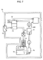
- FIG. 7 is a constitutional view showing the conventional fuel cell system described in Patent Document 1.
- fuel cell system 70 is made up of fuel cell 71, fuel gas generator 72, gas-liquid separator 74, heat exchanger 75, degasifier 76, condensed water tank 78, ion removal device 79, and pure water tank 77.
- Degasifier 76 performs degassing treatment on the combustion exhaust gas condensed water condensed in heat exchanger 75 by means of exhaust air exhausted from fuel cell 71.
- Condensed water tank 78 stores the fuel exhaust gas condensed water condensed in gas-liquid separator 74, and the combustion exhaust gas condensed water degassed by degasifier 76 after condensed in heat exchanger 75.
- Ion removal device 79 removes ions contained in the condensed water stored in condensed water tank 78. Deionized water from which ions have been removed is stored into pure water tank 77.
- the fuel exhaust gas condensed water condensed in gas-liquid separator 74 contains a large amount of carbon dioxide gas.
- the carbon dioxide gas is dissociated as bicarbonate ions in condensed water tank 78.
- the condensed water stored in condensed water tank 78 contains a large amount of bicarbonate ions. This results in an increase in amount of ions to be removed in ion removal device 79.
- the present invention solves the foregoing conventional problem, and provides a fuel cell system which reduces a concentration of carbon dioxide gas contained in fuel exhaust gas condensed water, to stabilize an operating state over a long period of time.
- the fuel cell system of the present invention has: a condensed water tank for storing condensed water; an ion removal device for removing ions contained in the condensed water to generate deionized water; a fuel gas generator for generating fuel gas mainly composed of hydrogen through use of the deionized water; and an air supply device for supplying air.
- the present invention further has: a fuel cell for generating power by using the hydrogen contained in the fuel gas and the air supplied from the air supply device; and a gas-liquid separator for performing gas-liquid separation on fuel exhaust gas exhausted from the fuel cell into combustion gas and fuel exhaust gas condensed water.
- the combustion exhaust gas condensed water and the fuel exhaust gas condensed water are subjected to the degassing treatment by the degasifier.
- concentrations of carbon dioxide gas in the combustion exhaust gas condensed water and the fuel exhaust gas condensed water decrease, and a concentration of bicarbonate ions dissociated in the condensed water tank significantly decreases.
- FIG. 1 is a constitutional view showing a fuel cell system according to Embodiment 1 of the present invention.
- fuel cell system 10 according to the present embodiment has condensed water tank 18, ion removal device 19, water pump 110, fuel gas generator 12, air supply device 114, and fuel cell 11.
- Condensed water tank 18 stores condensed water.
- Ion removal device 19 removes ions in the condensed water supplied from condensed water tank 18, to turn the condensed water into deionized water.
- the deionized water is conveyed to fuel gas generator 12 by water pump 110. Having a supply of the deionized water, fuel gas generator 12 reforms city gas, to generate fuel gas mainly composed of hydrogen.
- fuel cell 11 Simultaneously with having a supply of air from air supply device 114, fuel cell 11 has a supply of the fuel gas from fuel gas generator 12. Fuel cell 11 generates power from hydrogen contained in the fuel gas supplied from fuel gas generator 12, and oxygen contained in the air supplied from air supply device 114.
- Condensed water tank 18 is, for example, made up of stainless, a resin, or the like, and stores condensed water.
- ion removal device 19 the inside of a container, which is for example made up of stainless, a resin, or the like, is filled with an ion exchange resin.
- the ion exchange resin adsorbs cations and anions in the condensed water, to deionize the condensed water so as to generate deionized water.
- fuel gas generator 12 a container, which is for example made up of stainless or the like, is filled with a catalyst carrying ruthenium on an alumina carrier.
- Fuel gas generator 12 brings city gas and the deionized water generated by ion removal device 19 into a chemical reaction at about 650°C, to generate hydrogen and carbon dioxide. In this case, the deionized water serves to make the chemical reaction proceed.
- fuel gas generator 12 for example, has a selective oxidation device or the like which oxidizes carbon monoxide, generated in trace amounts by the chemical reaction, to carbon dioxide.
- the selective oxidation device is, for example, configured by arranging a catalyst carrying platinum on an alumina carrier on the rear flow side.
- fuel cell 11 is made up of an aggregate stacked with a plurality of cells each including an anode (not shown) and a cathode (not shown) respectively on both sides of a hydrogen-ion conductive electrolyte membrane (not shown).
- the hydrogen ion conductive electrolyte membrane there is used a polymer obtained by attaching a side chain of a sulfone group to a main chain of carbon fluoride.
- the anode and the cathode there are used ones configured by making platinum particles as a catalyst carried on carbon black.
- fuel gas generator 12 is provided with combustion section 13.
- Combustion section 13 combusts the city gas at an early stage of the operation of fuel cell system 10, and combusts hydrogen in the fuel exhaust gas, having not been used in fuel cell 11 and exhausted, at the time of stable operation. In this manner, combustion section 13 heats the catalyst, filling the inside of fuel gas generator 12, to about 650°C.
- combustion exhaust gas is generated by the combustion of hydrogen.
- the combustion exhaust gas is conveyed from combustion section 13 to heat exchanger 15.
- Moisture contained in the combustion exhaust gas is condensed by heat exchange in heat exchanger 15, to become combustion exhaust gas condensed water, and then stored into condensed water tank 18.
- combustion section 13 At the start of the operation, city gas from a gas supply tube (not shown) and air for combustion from a combustion air supply fan (not shown) are supplied to combustion section 13, to start combustion.
- combustion exhaust gas generated by the combustion is conveyed to heat exchanger 15.
- Moisture contained in the combustion exhaust gas is condensed by heat exchange in heat exchanger 15 to become combustion exhaust gas condensed water, and then stored into condensed water tank 18.
- combustion section 13 heats a catalyst, filling the inside of fuel gas generator 12, to about 650°C.
- fuel gas generator 12 When the catalyst of fuel gas generator 12 is heated to about 650°C, fuel gas generator 12 performs the following operating actions. First, fuel gas generator 12 generates fuel gas mainly composed of hydrogen, for example through a reforming reaction of deionized water supplied from condensed water tank 18 via ion removal device 19 and water pump 110 with city gas supplied from a gas supply tube (not shown). Next, fuel cell 11 generates power through an electrochemical reaction between hydrogen in the supplied fuel gas and oxygen in the air supplied from air supply device 114. Hydrogen in the fuel exhaust gas, having not been used in fuel cell 11 and exhausted, is supplied to combustion section 13 of fuel gas generator 12. Fuel gas generator 12 combusts this hydrogen.
- Gas-liquid separator 14 provided between fuel cell 11 and fuel gas generator 12 separates the fuel exhaust gas into combustion gas as a gas component and fuel exhaust gas condensed water as a liquid component. Hydrogen in the fuel exhaust gas is contained in combustion gas, and supplied to combustion section 13 of fuel gas generator 12. In this manner, combustion gas as hydrogen-based reforming gas with a small content of moisture is subjected to combustion in combustion section 13, which is stable combustion without generation of soot or the like.
- combustion exhaust gas condensed water condensed by heat exchanger 15 is conveyed via combustion exhaust gas condensed water channel 111 to degasifier 16 arranged, for example, in a position where the combustion exhaust gas condensed water drops on the side below heat exchanger 15.
- combustion exhaust gas condensed water channel 111 is not an essential constitution. For example, there is a configuration where heat exchanger 15 is united with degasifier 16 without use of combustion exhaust gas condensed water channel 111.
- fuel exhaust gas condensed water separated by gas-liquid separator 14 is conveyed via fuel exhaust gas condensed water channel 112 to degasifier 16 arranged, for example, in a position where the fuel exhaust gas condensed water drops on the side below gas-liquid separator 14.
- fuel exhaust gas condensed water channel 112 is not an essential constitution.
- gas-liquid separator 14 is united with degasifier 16 without use of fuel exhaust gas condensed water channel 112.
- degasifier 16 filler 17, which is for example made up of a Raschig ring or the like, is filled.
- Degassing air having been conveyed from fan 113, is allowed to flow into degasifier 16, for example, from the lower side thereof through air supply port 115 provided in condensed water tank 18.
- the combustion exhaust gas condensed water and the fuel exhaust gas condensed water which flow into degasifier 16 from the topside thereof and the degassing air which flows into degasifier 16 from the underside thereof come in contact with each other, as flowing in directions opposed to each other.
- the combustion exhaust gas condensed water and the fuel exhaust gas condensed water after removing carbon dioxide gas contained therein are stored into condensed water tank 18 as condensed water.
- the condensed water stored in condensed water tank 18 is conveyed to ion removal device 19 by water pump 110.
- the condensed water is subjected to ion removal by ion removal device 19, and then supplied to fuel gas generator 12 as deionized water.
- the property of the condensed water stored in condensed water tank 18 after 24-hour continuous operation of fuel cell system 10 of the present embodiment was evaluated from an electric conductivity and the concentration of bicarbonate ions.
- the electric conductivity was 5 ⁇ S/cm and the bicarbonate ion concentration was 3.1 mg/L.
- a similar evaluation was performed on the conventional fuel cell system where only the combustion exhaust gas condensed water is subjected to the degassing treatment, and the fuel exhaust gas condensed water is directly stored into condensed water tank 18 without being subjected to the degassing treatment.
- the electric conductivity was 10 ⁇ S/cm and the bicarbonate ion concentration was 12.4 mg/L.
- the condensed water of fuel cell system 10 of the present embodiment has a one-half electric conductivity and a one-quarter bicarbonate ion amount as compared with those of the condensed water of the conventional fuel cell system. It is seen from this result that, according to the present embodiment, the decrease in amount of bicarbonate ions leads to improvement in durability of ion removal device 19 about fourfold. Therefore, fuel cell system 10 is stably operated over a long period of time.
- FIG. 2 is a constitutional view showing the fuel cell system according to Embodiment 2 of the present invention. It should be noted that in FIG. 2 , the same reference numerals are used to describe the same constitutional elements as those in FIG. 1 . As shown in FIG. 2 , fuel cell system 20 of the present embodiment is different from Embodiment 1 in providing buffer tank 21 in fuel exhaust gas condensed water channel 112 that communicates gas-liquid separator 14 with degasifier 16.
- a position (height) of bottom surface 21A of buffer tank 21 is arranged so as to be located below a position (height) of top surface 16A of degasifier 16. Further, a position (height) of top surface 21B of buffer tank 21 is arranged so as to be located above the position (height) of top surface 16A of degasifier 16.
- the condensed water of fuel cell system 20 of the present embodiment has a one-half electric conductivity and a one-quarter bicarbonate ion amount as compared with those of the condensed water of the conventional fuel cell system. It is seen from this result that, according to the present embodiment, the decrease in bicarbonate ion amount leads to improvement in durability of ion removal device 19 about fourfold. Therefore, fuel cell system 20 is stably operated over a long period of time.
- FIGS. 3A and 3B are constitutional views of the fuel cell system according to Embodiment 3 of the present invention.
- FIG. 3A shows a state where a water level of the fuel exhaust gas condensed water stored in the buffer tank is lower than a previously set reference water level.
- FIG. 3B shows a state where the water level of the fuel exhaust gas condensed water stored in the buffer tank is not lower than the previously set reference water level.
- FIGS. 3A, 3B the same reference numerals are used to describe the same constitutional elements as those in FIG. 1 . As shown in FIGS.
- fuel cell system 30 of the present embodiment is different from Embodiment 1 in providing, in combustion exhaust gas condensed water channel 112, buffer tank 31 provided with water level sensor 33, cutoff valve 32, and control section 34 that controls opening and closing of cutoff valve 32.
- control section 34 closes off cutoff valve 32.
- fuel exhaust gas condensed water channel 112 between buffer tank 31 and degasifier 16 is cut off by cutoff valve 32. That is, the flow of the degassing air which back-flows along fuel exhaust gas condensed water channel 112 from degasifier 16 and the flow of the fuel exhaust gas which has failed to be separated from gas-liquid separator 14 and flows along fuel exhaust gas condensed water channel 112 are cut off by cutoff valve 32.
- control section 34 opens cutoff valve 32.
- the fuel exhaust gas condensed water drops from buffer tank 31 into degasifier 16.
- the fuel exhaust gas condensed water is subjected to the degassing treatment by degasifier 16, and then stored into condensed water tank 18. That is, the degassing air which back-flows via degasifier 16 and the fuel exhaust gas which has failed to be separated from gas-liquid separator 14 and flows along fuel exhaust gas condensed water channel 112 are water-sealed by the fuel exhaust gas condensed water stored in buffer tank 31.
- the reference water level described above is, for example, on the order of 10 cm in the case of a buffer tank of an ordinary floor-mounted fuel cell system for domestic use.
- this reference water level is not restricted to the above water level.
- the reference water level is, for example, set to a water level where the water-sealing is held in buffer tank 31 in accordance with pressure of the degassing air which is conveyed from fan 113 and pressure of the fuel exhaust gas which has failed to be separated in gas-liquid separator 14 and leaks.
- the property of the condensed water stored in condensed water tank 18 after 24-hour continuous operation of fuel cell system 30 of the present embodiment was evaluated from an electric conductivity and the concentration of bicarbonate ions.
- the electric conductivity was 5 ⁇ S/cm and the bicarbonate ion concentration was 3.1 mg/L.
- a similar evaluation was performed on the conventional fuel cell system where only the combustion exhaust gas condensed water is subjected to the degassing treatment, and the fuel exhaust gas condensed water is directly stored into condensed water tank 18 without being subjected to the degassing treatment.
- the electric conductivity was 10 ⁇ S/cm and the bicarbonate ion concentration was 12.4 mg/L.
- the condensed water of fuel cell system 30 of the present embodiment has a one-half electric conductivity and a one-quarter bicarbonate ion amount as compared with those of the condensed water of the conventional fuel cell system. It is seen from this result that, according to the present embodiment, the decrease in bicarbonate ion amount leads to improvement in durability of ion removal device 19 about fourfold. Therefore, fuel cell system 30 is stably operated over a long period of time.
- FIG. 4 is a constitutional view showing the fuel cell system according to Embodiment 4 of the present invention. It should be noted that in FIG. 4 , the same reference numerals are used to describe the same constitutional elements as those in FIG. 1 . As shown in FIG. 4 , fuel cell system 40 of the present embodiment is different from Embodiment 1 in using exhaust air from fuel cell 11 instead of obtaining degassing air to be supplied to degasifier 16 from fan 113 shown in FIG. 1 .
- the exhaust air heated by power generation of fuel cell 11 can be used for the degassing treatment.
- the efficiency in reaction of the heated exhaust gas with carbon dioxide gas has been improved, the efficiency in degassing treatment improves. That is, the concentrations of bicarbonate ions in the fuel exhaust gas condensed water and the combustion exhaust gas condensed water are further reduced.
- fan 113 without the use of fan 113, it is possible to realize simplification and size reduction of fuel cell system 40.
- the condensed water of fuel cell system 40 of the present embodiment has a one-half electric conductivity and a one-quarter bicarbonate ion amount as compared with those of the condensed water of the conventional fuel cell system. It is seen from this result that, according to the present embodiment, the decrease in bicarbonate ion amount leads to improvement in durability of ion removal device 19 about fourfold. Therefore, fuel cell system 40 is stably operated over a long period of time.
- the exhaust air exhausted from fuel cell 11 is conveyed to air supply port 115 of condensed water tank 18 via exhaust air channel 51, and further allowed to flow through degasifier 16 as the degassing air.
- the exhaust air is preferably allowed to flow from the lower portion to the upper portion of degasifier 16 with fuel cell system 50 being in a standing state. This brings carbon dioxide gas and the degassing air into oppositely contact with each other, to make the contact time longer so as to improve the efficiency of the degassing treatment.
- the exhaust air heated by power generation of fuel cell 11 can be used for the degassing treatment.
- the efficiency in reaction of the heated exhaust gas with carbon dioxide gas has been improved, the efficiency in degassing treatment improves. That is, the concentrations of bicarbonate ions in the fuel exhaust gas condensed water and the combustion exhaust gas condensed water are further reduced.
- fan 113 without the use of fan 113, it is possible to realize simplification and size reduction of fuel cell system 50.
- buffer tank 21 water-seals degassing air which back-flows along fuel exhaust gas condensed water channel 112 from degasifier 16 and fuel exhaust gas which has failed to be separated from gas-liquid separator 14 and flows along fuel exhaust gas condensed water channel 112. This results in prevention of occurrence of a reaction due to contact between the fuel exhaust gas and the degassing air. Therefore, fuel cell system 50 is stably and safely operated over a long period of time.
- the property of the condensed water stored in condensed water tank 18 after 24-hour continuous operation of fuel cell system 50 of the present embodiment was evaluated from an electric conductivity and the concentration of bicarbonate ions.
- the electric conductivity was 5 ⁇ S/cm and the bicarbonate ion concentration was 3.1 mg/L.
- a similar evaluation was performed on the conventional fuel cell system where only the combustion exhaust gas condensed water is subjected to the degassing treatment, and the fuel exhaust gas condensed water is directly stored into condensed water tank 18 without being subjected to the degassing treatment.
- the electric conductivity was 10 ⁇ S/cm and the bicarbonate ion concentration was 12.4 mg/L.
- the condensed water of fuel cell system 50 of the present embodiment has a one-half electric conductivity and a one-quarter bicarbonate ion amount as compared with those of the condensed water of the conventional fuel cell system. It is seen from this result that, according to the present embodiment, the decrease in bicarbonate ion amount leads to improvement in durability of ion removal device 19 about fourfold. Therefore, fuel cell system 50 is stably operated over a long period of time.
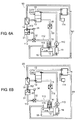
- FIGS. 6A and 6B are constitutional views of the fuel cell system according to Embodiment 6 of the present invention.
- FIG. 6A shows a state where a water level of the fuel exhaust gas condensed water stored in a buffer tank is lower than a previously set reference water level.
- FIG. 6B shows a state where the water level of the fuel exhaust gas condensed water stored in the buffer tank is not lower than the previously set reference water level.
- FIGS. 6A, 6B the same reference numerals are used to describe the same constitutional elements as those in FIGS. 3A, 3B . As shown in FIGS.
- fuel cell system 60 of the present embodiment is different from Embodiment 3 in using exhaust air from fuel cell 11 instead of obtaining degassing air to be supplied to degasifier 16 from fan 113 shown in FIGS. 3A, 3B . It should be noted that other configurations and functions are similar to Embodiment 3.
- the exhaust air exhausted from fuel cell 11 is conveyed to air supply port 115 of condensed water tank 18 via exhaust air channel 61, and further allowed to flow through degasifier 16 as the degassing air.
- exhaust air is preferably allowed to flow from the lower portion to the upper portion of degasifier 16 with fuel cell system 60 being in a standing state. This brings carbon dioxide gas and the degassing air into oppositely contact with each other, to make the contact time longer so as to improve the efficiency of the degassing treatment.
- cutoff valve 32 or water-sealing of fuel exhaust gas condensed water can cut off a back-flow of exhaust air to be used for degassing treatment to fuel exhaust gas condensed water channel 112 via degasifier 16, as in Embodiment 3. Moreover, it is possible to reliably cut off a flow of fuel exhaust gas, which has failed to be separated in gas-liquid separator 14, into degasifier 16. This results in prevention of occurrence of a reaction due to contact between the fuel exhaust gas and the degassing air. Therefore, the safety of fuel cell system 60 is ensured.
- the property of the condensed water stored in condensed water tank 18 after 24-hour continuous operation of fuel cell system 60 of the present embodiment was evaluated from an electric conductivity and the concentration of bicarbonate ions.
- the electric conductivity was 5 ⁇ S/cm and the bicarbonate ion concentration was 3.1 mg/L.
- a similar evaluation was performed on the conventional fuel cell system where only the combustion exhaust gas condensed water is subjected to the degassing treatment, and the fuel exhaust gas condensed water is directly stored into condensed water tank 18 without being subjected to the degassing treatment.
- the electric conductivity was 10 ⁇ S/cm and the bicarbonate ion concentration was 12.4 mg/L.
- the condensed water of fuel cell system 60 of the present embodiment has a one-half electric conductivity and a one-quarter bicarbonate ion amount as compared with those of the condensed water of the conventional fuel cell system. It is seen from this result that, according to the present embodiment, the decrease in bicarbonate ion amount leads to improvement in durability of ion removal device 19 about fourfold. Therefore, fuel cell system 60 is stably operated over a long period of time.
- each of the embodiments by taking as an example the configuration of allowing the degassing air to flow into degasifier 16 from the lower portion thereof, this is not restrictive.
- the degassing air in this case is the exhaust air in Embodiments 4 to 6.
- buffer tank 21 or 31 that stores the fuel exhaust gas condensed water separated in gas-liquid separator 14 is configured separately from gas-liquid separator 14 in each of Embodiments 2, 3, 5, 6, this is not restrictive.
- buffer tank 21 or 31 is provided in the lower portion of gas-liquid separator 14, integrally with gas-liquid separator 14, and the configuration exerts a similar effect.
- fuel cells such as a phosphoric acid fuel cell, a solid oxide fuel cell, a polymer electrolyte fuel cell, and a molten carbonate fuel cell can be applied to fuel cell 11 mounted in fuel cell system 10, 20, 30, 40, 50 or 60 according to each of the embodiments.
- a fuel cell with an operating temperature at not higher than 100°C such as the polymer electrolyte fuel cell
- carbon dioxide gas is contained in a large amount in the fuel exhaust gas condensed water, as compared with the other fuel cells. Accordingly, the present invention has a specific effect of being able to efficiently perform the degassing treatment on carbon dioxide gas.
- gas-liquid separator 14 is formed in a dedicated configuration in each of the embodiments, another configuration capable of performing separation into gas and liquid is usable instead of the dedicated configuration.
- gas-liquid separation can be performed through use of a heat exchanger, a condenser, or the like.
- the present invention has: a condensed water tank for storing condensed water; an ion removal device for removing ions contained in the condensed water to generate deionized water; a fuel gas generator for generating fuel gas mainly composed of hydrogen through use of the deionized water; and an air supply device for supplying air.
- the present invention further has: a fuel cell for generating power by using the hydrogen contained in the fuel gas and the air supplied from the air supply device; and a gas-liquid separator for performing gas-liquid separation on fuel exhaust gas exhausted from the fuel cell into combustion gas and fuel exhaust gas condensed water.
- the present invention further has: a combustion section provided in the fuel gas generator, for combusting hydrogen in the combustion gas separated by the gas-liquid separator; and a heat exchanger for exchanging heat of combustion exhaust gas generated by the combustion in the combustion section, to condense moisture in the combustion exhaust gas and generating combustion exhaust gas condensed water.
- the present invention further has a degasifier for producing the condensed water and the combustion exhaust gas condensed water and the combustion exhaust gas condensed water into contact with degassing air, and removing carbon dioxide gas contained in the fuel exhaust gas condensed water and the combustion exhaust gas condensed water.
- the combustion exhaust gas condensed water and the fuel exhaust gas condensed water are subjected to degassing treatment by the degasifier. Therefore, the combustion exhaust gas condensed water and the fuel exhaust gas condensed water are collected after reduction in concentration of carbon dioxide gas.
- This collected condensed water has an extremely low concentration of bicarbonate ions that are dissociated in the condensed water tank. This results in a fuel cell system which reduces an amount of ions to be removed in the ion removal device, to improve the durability of the ion removal device and stabilize an operating state over a long period of time.
- the present invention further includes a buffer tank for storing the fuel exhaust gas condensed water separated in the gas-liquid separator. Further, in the present invention, a position of a bottom surface of the buffer tank is arranged below a position of a top surface of the degasifier, and a position of a top surface of the buffer tank is arranged above the position of the top surface of the degasifier.
- the present invention further includes: a buffer tank for storing the fuel exhaust gas condensed water separated in the gas-liquid separator, and a cutoff valve provided between the buffer tank and the degasifier, for cutting off a flow of the fuel exhaust gas condensed water.
- the present invention further includes a water level sensor for detecting a water level of the fuel exhaust gas condensed water stored in the buffer tank, and opening and closing of the cutoff valve are controlled based on information detected by the water level sensor.
- the degassing treatment is performed on the fuel exhaust gas condensed water in a safer manner.
- the cutoff valve is first opened, and the fuel exhaust gas condensed water is conveyed from the buffer tank to the degasifier. That is, the degassing air which back-flows and the fuel exhaust gas which has failed to be separated in the gas-liquid separator are water-sealed by the fuel exhaust gas condensed water stored in the buffer tank.
- the cutoff valve is first closed, and the channel is cut off.
- the degassing air which back-flows along the channel and the fuel exhaust gas which has failed to be separated in the gas-liquid separator are cut off by the cutoff valve. This results in prevention of occurrence of a reaction due to contact between the fuel exhaust gas and the degassing air, to give a fuel cell system stably and safely operated over a long period of time.
- the present invention allows the degassing air into the degasifier in a direction opposed to a direction where the fuel exhaust gas condensed water and the combustion exhaust gas condensed water flow into the degasifier.
- the fuel exhaust gas condensed water and the combustion exhaust gas condensed water which are infused into the degasifier and the degassing air which are supplied into the degasifier are oppositely in contact with each other, to make the contact time longer so as to improve the efficiency of the degassing treatment. Consequently, the concentrations of carbon dioxide gas contained in the fuel exhaust gas condensed water and the combustion exhaust gas condensed water are more efficiently reduced, thereby to further improve the durability of the ion removal device. This thus gives a fuel cell system stably and safely operated over a long period of time.
- the present invention supplies the degasifier with exhaust air exhausted from the fuel cell, as the degassing air. This eliminates the need for arrangement of the fan, and allows the fuel cell system to have a simple configuration. Further, since the exhaust air has been heated to a predetermined temperature by fuel cell, the efficiency of the degassing treatment improves.
- a fuel cell system of the present invention is capable of reducing a concentration of carbon dioxide gas contained in fuel exhaust gas condensed water obtained by condensing fuel exhaust gas, and thereby the system is usable for a stationary or mobile fuel cell system which is desired to have high reliability and a long life.
Abstract
Description
- The present invention relates to a fuel cell system.
- A conventional fuel cell system, for example as disclosed in Patent Document 1, collects hydrogen contained in fuel exhaust gas exhausted from a fuel cell and combusts the collected hydrogen. The conventional fuel cell system collects water from combustion exhaust gas exhausted by the combustion, and removes ions from the collected water by means of an ion removal device. The conventional fuel cell system generates hydrogen that is used for power generation of the fuel cell through use of the deionized water from which ions have been removed.
-
FIG. 7 is a constitutional view showing the conventional fuel cell system described in Patent Document 1. As shown inFIG. 7 ,fuel cell system 70 is made up offuel cell 71,fuel gas generator 72, gas-liquid separator 74,heat exchanger 75,degasifier 76, condensedwater tank 78,ion removal device 79, andpure water tank 77. -
Fuel gas generator 72 generates fuel gas to be supplied tofuel cell 71. Gas-liquid separator 74 condenses moisture contained in fuel exhaust gas exhausted fromfuel cell 71, and separates the moisture into fuel exhaust gas condensed water and combustion gas containing hydrogen.Combustion section 73 offuel gas generator 72 combusts the combustion gas containing hydrogen separated by gas-liquid separator 74.Heat exchanger 75 performs heat exchange to condense combustion exhaust gas exhausted by the combustion incombustion section 73, and generates combustion exhaust gas condensed water. -
Degasifier 76 performs degassing treatment on the combustion exhaust gas condensed water condensed inheat exchanger 75 by means of exhaust air exhausted fromfuel cell 71. Condensedwater tank 78 stores the fuel exhaust gas condensed water condensed in gas-liquid separator 74, and the combustion exhaust gas condensed water degassed bydegasifier 76 after condensed inheat exchanger 75.Ion removal device 79 removes ions contained in the condensed water stored in condensedwater tank 78. Deionized water from which ions have been removed is stored intopure water tank 77. - However, in the conventional fuel cell system, the fuel exhaust gas condensed water condensed in gas-
liquid separator 74 contains a large amount of carbon dioxide gas. The carbon dioxide gas is dissociated as bicarbonate ions in condensedwater tank 78. For this reason, the condensed water stored in condensedwater tank 78 contains a large amount of bicarbonate ions. This results in an increase in amount of ions to be removed inion removal device 79. There has thus been a problem in that the durability ofion removal device 79 deteriorates to destabilize the operation of the fuel cell system in a short period of time. -
- Patent Document 1: Unexamined Japanese Patent Publication No.
2005-129334 - The present invention solves the foregoing conventional problem, and provides a fuel cell system which reduces a concentration of carbon dioxide gas contained in fuel exhaust gas condensed water, to stabilize an operating state over a long period of time.
- The fuel cell system of the present invention has: a condensed water tank for storing condensed water; an ion removal device for removing ions contained in the condensed water to generate deionized water; a fuel gas generator for generating fuel gas mainly composed of hydrogen through use of the deionized water; and an air supply device for supplying air. The present invention further has: a fuel cell for generating power by using the hydrogen contained in the fuel gas and the air supplied from the air supply device; and a gas-liquid separator for performing gas-liquid separation on fuel exhaust gas exhausted from the fuel cell into combustion gas and fuel exhaust gas condensed water. The present invention further has: a combustion section provided in the fuel gas generator, for combusting hydrogen in the combustion gas separated by the gas-liquid separator; and a heat exchanger for exchanging heat of combustion exhaust gas generated by the combustion in the combustion section to condense moisture in the combustion exhaust gas and generating combustion exhaust gas condensed water. The present invention further has a degasifier for producing the condensed water by bringing the fuel exhaust gas condensed water and the combustion exhaust gas condensed water into contact with degassing air and removing carbon dioxide gas contained in the combustion exhaust gas condensed water and the fuel exhaust gas condensed water.
- According to such a configuration, the combustion exhaust gas condensed water and the fuel exhaust gas condensed water are subjected to the degassing treatment by the degasifier. Thereby, concentrations of carbon dioxide gas in the combustion exhaust gas condensed water and the fuel exhaust gas condensed water decrease, and a concentration of bicarbonate ions dissociated in the condensed water tank significantly decreases. This results in a decreased amount of ions to be removed in the ion removal device, to improve the durability of the ion removal device and keep the fuel cell system in a stably operating state over a long period of time. Accordingly, the fuel cell system of the present invention is a fuel cell system which reduces the concentration of bicarbonate ions in the condensed water stored in the condensed water tank, thereby improving the durability of the ion removal device and stabilizing an operating state over a long period of time.
-
-
FIG. 1 is a constitutional view showing a fuel cell system according to Embodiment 1 of the present invention. -
FIG. 2 is a constitutional view showing a fuel cell system according to Embodiment 2 of the present invention. -
FIG. 3A is a constitutional view of a fuel cell system according to Embodiment 3 of the present invention. -
FIG. 3B is a constitutional view showing another state of the fuel cell system in Embodiment 3. -
FIG. 4 is a constitutional view showing a fuel cell system according toEmbodiment 4 of the present invention. -
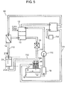
FIG. 5 is a constitutional view showing a fuel cell system according to Embodiment 5 of the present invention. -
FIG. 6A is a constitutional view of a fuel cell system according to Embodiment 6 of the present invention. -
FIG. 6B is a constitutional view showing another state of the fuel cell system in Embodiment 6. -
FIG. 7 is a constitutional view showing a conventional fuel cell system. -
FIG. 1 is a constitutional view showing a fuel cell system according to Embodiment 1 of the present invention. As shown inFIG. 1 ,fuel cell system 10 according to the present embodiment has condensedwater tank 18,ion removal device 19,water pump 110,fuel gas generator 12,air supply device 114, andfuel cell 11. Condensedwater tank 18 stores condensed water.Ion removal device 19 removes ions in the condensed water supplied from condensedwater tank 18, to turn the condensed water into deionized water. The deionized water is conveyed tofuel gas generator 12 bywater pump 110. Having a supply of the deionized water,fuel gas generator 12 reforms city gas, to generate fuel gas mainly composed of hydrogen. Simultaneously with having a supply of air fromair supply device 114,fuel cell 11 has a supply of the fuel gas fromfuel gas generator 12.Fuel cell 11 generates power from hydrogen contained in the fuel gas supplied fromfuel gas generator 12, and oxygen contained in the air supplied fromair supply device 114. - Hereinafter, a material and a function of each constitutional element constituting
fuel cell system 10 according to the present embodiment are specifically described. Condensedwater tank 18 is, for example, made up of stainless, a resin, or the like, and stores condensed water. Inion removal device 19, the inside of a container, which is for example made up of stainless, a resin, or the like, is filled with an ion exchange resin. The ion exchange resin adsorbs cations and anions in the condensed water, to deionize the condensed water so as to generate deionized water. - Further, in
fuel gas generator 12, a container, which is for example made up of stainless or the like, is filled with a catalyst carrying ruthenium on an alumina carrier.Fuel gas generator 12 brings city gas and the deionized water generated byion removal device 19 into a chemical reaction at about 650°C, to generate hydrogen and carbon dioxide. In this case, the deionized water serves to make the chemical reaction proceed. It should be noted thatfuel gas generator 12, for example, has a selective oxidation device or the like which oxidizes carbon monoxide, generated in trace amounts by the chemical reaction, to carbon dioxide. The selective oxidation device is, for example, configured by arranging a catalyst carrying platinum on an alumina carrier on the rear flow side. - Moreover,
fuel cell 11 is made up of an aggregate stacked with a plurality of cells each including an anode (not shown) and a cathode (not shown) respectively on both sides of a hydrogen-ion conductive electrolyte membrane (not shown). As the hydrogen ion conductive electrolyte membrane, there is used a polymer obtained by attaching a side chain of a sulfone group to a main chain of carbon fluoride. Further, as the anode and the cathode, there are used ones configured by making platinum particles as a catalyst carried on carbon black. With this configuration,fuel cell 11 brings hydrogen in the fuel gas supplied fromfuel gas generator 12 to the anode, and oxygen in the air supplied fromair supply device 114 to the cathode into an electrochemical reaction, to generate power. - Further,
fuel gas generator 12 is provided withcombustion section 13.Combustion section 13 combusts the city gas at an early stage of the operation offuel cell system 10, and combusts hydrogen in the fuel exhaust gas, having not been used infuel cell 11 and exhausted, at the time of stable operation. In this manner,combustion section 13 heats the catalyst, filling the inside offuel gas generator 12, to about 650°C. - In
combustion section 13, combustion exhaust gas is generated by the combustion of hydrogen. The combustion exhaust gas is conveyed fromcombustion section 13 toheat exchanger 15. Moisture contained in the combustion exhaust gas is condensed by heat exchange inheat exchanger 15, to become combustion exhaust gas condensed water, and then stored into condensedwater tank 18. - Hereinafter, operating actions of
fuel cell system 10 of the present embodiment are described. At the start of the operation, city gas from a gas supply tube (not shown) and air for combustion from a combustion air supply fan (not shown) are supplied tocombustion section 13, to start combustion. Incombustion section 13, combustion exhaust gas generated by the combustion is conveyed toheat exchanger 15. Moisture contained in the combustion exhaust gas is condensed by heat exchange inheat exchanger 15 to become combustion exhaust gas condensed water, and then stored into condensedwater tank 18. Simultaneously,combustion section 13 heats a catalyst, filling the inside offuel gas generator 12, to about 650°C. - When the catalyst of
fuel gas generator 12 is heated to about 650°C,fuel gas generator 12 performs the following operating actions. First,fuel gas generator 12 generates fuel gas mainly composed of hydrogen, for example through a reforming reaction of deionized water supplied fromcondensed water tank 18 viaion removal device 19 andwater pump 110 with city gas supplied from a gas supply tube (not shown). Next,fuel cell 11 generates power through an electrochemical reaction between hydrogen in the supplied fuel gas and oxygen in the air supplied fromair supply device 114. Hydrogen in the fuel exhaust gas, having not been used infuel cell 11 and exhausted, is supplied tocombustion section 13 offuel gas generator 12.Fuel gas generator 12 combusts this hydrogen. - Gas-
liquid separator 14 provided betweenfuel cell 11 andfuel gas generator 12 separates the fuel exhaust gas into combustion gas as a gas component and fuel exhaust gas condensed water as a liquid component. Hydrogen in the fuel exhaust gas is contained in combustion gas, and supplied tocombustion section 13 offuel gas generator 12. In this manner, combustion gas as hydrogen-based reforming gas with a small content of moisture is subjected to combustion incombustion section 13, which is stable combustion without generation of soot or the like. - In the following, a flow of condensed water in
fuel cell system 10 of the present embodiment is described. First, combustion exhaust gas condensed water condensed byheat exchanger 15 is conveyed via combustion exhaust gas condensedwater channel 111 to degasifier 16 arranged, for example, in a position where the combustion exhaust gas condensed water drops on the side belowheat exchanger 15. It is to be noted that combustion exhaust gas condensedwater channel 111 is not an essential constitution. For example, there is a configuration whereheat exchanger 15 is united withdegasifier 16 without use of combustion exhaust gas condensedwater channel 111. - Meanwhile, the fuel exhaust gas condensed water separated by gas-
liquid separator 14 is conveyed via fuel exhaust gas condensedwater channel 112 to degasifier 16 arranged, for example, in a position where the fuel exhaust gas condensed water drops on the side below gas-liquid separator 14. It is to be noted that fuel exhaust gas condensedwater channel 112 is not an essential constitution. For example, there is a configuration where gas-liquid separator 14 is united withdegasifier 16 without use of fuel exhaust gas condensedwater channel 112. - The inside of
degasifier 16,filler 17, which is for example made up of a Raschig ring or the like, is filled. Degassing air, having been conveyed fromfan 113, is allowed to flow intodegasifier 16, for example, from the lower side thereof throughair supply port 115 provided incondensed water tank 18. In this case, the combustion exhaust gas condensed water and the fuel exhaust gas condensed water which flow intodegasifier 16 from the topside thereof and the degassing air which flows intodegasifier 16 from the underside thereof come in contact with each other, as flowing in directions opposed to each other. As a result, the combustion exhaust gas condensed water and the fuel exhaust gas condensed water after removing carbon dioxide gas contained therein are stored into condensedwater tank 18 as condensed water. The condensed water stored incondensed water tank 18 is conveyed toion removal device 19 bywater pump 110. The condensed water is subjected to ion removal byion removal device 19, and then supplied to fuelgas generator 12 as deionized water. - With the above configuration, carbon dioxide gas contained in the combustion exhaust gas condensed water is removed, while carbon dioxide gas contained in the fuel exhaust gas condensed water is also removed. Hence the concentration of bicarbonate ions dissociated in the condensed water stored in
condensed water tank 18 significantly decreases. This results in a further decreased amount of ions to be removed inion removal device 19, to dramatically improve the durability ofion removal device 19. - Hereinafter, an effect is specifically described, taking a property of the condensed water stored in
condensed water tank 18 as a reference. The property of the condensed water stored incondensed water tank 18 after 24-hour continuous operation offuel cell system 10 of the present embodiment was evaluated from an electric conductivity and the concentration of bicarbonate ions. As a result, the electric conductivity was 5 µS/cm and the bicarbonate ion concentration was 3.1 mg/L. Meanwhile, for the sake of comparison, a similar evaluation was performed on the conventional fuel cell system where only the combustion exhaust gas condensed water is subjected to the degassing treatment, and the fuel exhaust gas condensed water is directly stored into condensedwater tank 18 without being subjected to the degassing treatment. As a result, the electric conductivity was 10 µS/cm and the bicarbonate ion concentration was 12.4 mg/L. - That is, the condensed water of
fuel cell system 10 of the present embodiment has a one-half electric conductivity and a one-quarter bicarbonate ion amount as compared with those of the condensed water of the conventional fuel cell system. It is seen from this result that, according to the present embodiment, the decrease in amount of bicarbonate ions leads to improvement in durability ofion removal device 19 about fourfold. Therefore,fuel cell system 10 is stably operated over a long period of time. - Hereinafter, a fuel cell system according to Embodiment 2 of the present invention is described with reference to the drawings.
FIG. 2 is a constitutional view showing the fuel cell system according to Embodiment 2 of the present invention. It should be noted that inFIG. 2 , the same reference numerals are used to describe the same constitutional elements as those inFIG. 1 . As shown inFIG. 2 ,fuel cell system 20 of the present embodiment is different from Embodiment 1 in providingbuffer tank 21 in fuel exhaust gas condensedwater channel 112 that communicates gas-liquid separator 14 withdegasifier 16. -
Buffer tank 21 is, for example, made up of stainless, a resin or the like, and is connected to gas-liquid separator 14 anddegasifier 16 via fuel exhaust gas condensedwater channel 112.Buffer tank 21 stores the fuel exhaust gas condensed water separated from the combustion exhaust gas by gas-liquid separator 14. - In this case, a position (height) of
bottom surface 21A ofbuffer tank 21 is arranged so as to be located below a position (height) oftop surface 16A ofdegasifier 16. Further, a position (height) oftop surface 21B ofbuffer tank 21 is arranged so as to be located above the position (height) oftop surface 16A ofdegasifier 16. - With this configuration,
buffer tank 21 constantly stores a fixed amount of fuel exhaust gas condensed water. Thereby,buffer tank 21 water-seals the degassing air which back-flows along fuel exhaust gas condensedwater channel 112 fromdegasifier 16 and the fuel exhaust gas which has failed to be separated from gas-liquid separator 14 and flows along fuel exhaust gas condensedwater channel 112. This results in prevention of occurrence of a reaction due to contact between the fuel exhaust gas and the degassing air. Therefore,fuel cell system 20 is stably and safely operated over a long period of time. - Furthermore, as in Embodiment 1, carbon dioxide gas contained in the combustion exhaust gas condensed water is removed, while carbon dioxide gas contained in the fuel exhaust gas condensed water is also removed. Hence the concentration of bicarbonate ions dissociated in the condensed water stored in
condensed water tank 18 significantly decreases. This results in a further decreased amount of ions to be removed inion removal device 19, to dramatically improve the durability ofion removal device 19. - Hereinafter, an effect is specifically described, taking a property of the condensed water stored in
condensed water tank 18 as a reference. The property of the condensed water stored incondensed water tank 18 after 24-hour continuous operation offuel cell system 20 of the present embodiment was evaluated from an electric conductivity and the concentration of bicarbonate ions. As a result, the electric conductivity was 5 µS/cm and the bicarbonate ion concentration was 3.1 mg/L. Meanwhile, for the sake of comparison, a similar evaluation was performed on the conventional fuel cell system where only the combustion exhaust gas condensed water is subjected to the degassing treatment, and the fuel exhaust gas condensed water is directly stored into condensedwater tank 18 without being subjected to the degassing treatment. As a result, the electric conductivity was 10 µS/cm and the bicarbonate ion concentration was 12.4 mg/L. - That is, the condensed water of
fuel cell system 20 of the present embodiment has a one-half electric conductivity and a one-quarter bicarbonate ion amount as compared with those of the condensed water of the conventional fuel cell system. It is seen from this result that, according to the present embodiment, the decrease in bicarbonate ion amount leads to improvement in durability ofion removal device 19 about fourfold. Therefore,fuel cell system 20 is stably operated over a long period of time. - Hereinafter, a fuel cell system according to Embodiment 3 of the present invention is described with reference to the drawings.
FIGS. 3A and 3B are constitutional views of the fuel cell system according to Embodiment 3 of the present invention.FIG. 3A shows a state where a water level of the fuel exhaust gas condensed water stored in the buffer tank is lower than a previously set reference water level.FIG. 3B shows a state where the water level of the fuel exhaust gas condensed water stored in the buffer tank is not lower than the previously set reference water level. It should be noted that inFIGS. 3A, 3B , the same reference numerals are used to describe the same constitutional elements as those inFIG. 1 . As shown inFIGS. 3A, 3B ,fuel cell system 30 of the present embodiment is different from Embodiment 1 in providing, in combustion exhaust gas condensedwater channel 112,buffer tank 31 provided withwater level sensor 33,cutoff valve 32, andcontrol section 34 that controls opening and closing ofcutoff valve 32. -
Buffer tank 31 is, for example, made up of stainless, a resin or the like, and is connected to gas-liquid separator 14 andcutoff valve 32 via fuel exhaust gas condensedwater channel 112. Further,cutoff valve 32 is connected todegasifier 16.Water level sensor 33 detects a water level of the fuel exhaust gas condensed water stored inbuffer tank 31.Control section 34 controls opening and closing ofcutoff valve 32 based on information detected bywater level sensor 33. Control of the opening and closing ofcutoff valve 32 bycontrol section 34 is described below. - Flows of the fuel exhaust gas condensed water, the fuel exhaust gas and degassing air in fuel exhaust gas condensed
water channel 112 of the present embodiment are described with reference toFIGS. 3A and 3B . The fuel exhaust gas condensed water separated in gas-liquid separator 14 is stored intobuffer tank 31. - First, as shown in
FIG. 3A , whenwater level sensor 33 detects that the water level of the fuel exhaust gas condensed water stored inbuffer tank 31 is lower than the previously set reference water level,control section 34 closes offcutoff valve 32. Thereby, fuel exhaust gas condensedwater channel 112 betweenbuffer tank 31 anddegasifier 16 is cut off bycutoff valve 32. That is, the flow of the degassing air which back-flows along fuel exhaust gas condensedwater channel 112 fromdegasifier 16 and the flow of the fuel exhaust gas which has failed to be separated from gas-liquid separator 14 and flows along fuel exhaust gas condensedwater channel 112 are cut off bycutoff valve 32. - On the other hand, as shown in
FIG. 3B , whenwater level sensor 33 detects that the water level of the fuel exhaust gas condensed water stored inbuffer tank 31 is not lower than the previously set reference water level,control section 34 openscutoff valve 32. Thereby, the fuel exhaust gas condensed water drops frombuffer tank 31 intodegasifier 16. The fuel exhaust gas condensed water is subjected to the degassing treatment bydegasifier 16, and then stored into condensedwater tank 18. That is, the degassing air which back-flows viadegasifier 16 and the fuel exhaust gas which has failed to be separated from gas-liquid separator 14 and flows along fuel exhaust gas condensedwater channel 112 are water-sealed by the fuel exhaust gas condensed water stored inbuffer tank 31. - Herein, the reference water level described above is, for example, on the order of 10 cm in the case of a buffer tank of an ordinary floor-mounted fuel cell system for domestic use. In addition, this reference water level is not restricted to the above water level. The reference water level is, for example, set to a water level where the water-sealing is held in
buffer tank 31 in accordance with pressure of the degassing air which is conveyed fromfan 113 and pressure of the fuel exhaust gas which has failed to be separated in gas-liquid separator 14 and leaks. - With the above configuration, it is possible to cut off a back-flow of the degassing air to fuel exhaust gas condensed
water channel 112 viadegasifier 16. Further, it is possible to cut off a flow of the fuel exhaust gas, which has failed to be separated in gas-liquid separator 14, intodegasifier 16. This results in prevention of occurrence of a reaction due to contact between the fuel exhaust gas and the degassing air. Therefore, the safety offuel cell system 30 is ensured. - Furthermore, as in Embodiment 1, carbon dioxide gas contained in the combustion exhaust gas condensed water is removed, while carbon dioxide gas contained in the fuel exhaust gas condensed water is also removed. Hence the concentration of bicarbonate ions dissociated in the condensed water stored in
condensed water tank 18 significantly decreases. This results in a further decreased amount of ions to be removed inion removal device 19, to dramatically improve the durability ofion removal device 19. - Hereinafter, an effect is specifically described, taking a property of the condensed water stored in
condensed water tank 18 as a reference. First, the property of the condensed water stored incondensed water tank 18 after 24-hour continuous operation offuel cell system 30 of the present embodiment was evaluated from an electric conductivity and the concentration of bicarbonate ions. As a result, the electric conductivity was 5 µS/cm and the bicarbonate ion concentration was 3.1 mg/L. Meanwhile, for the sake of comparison, a similar evaluation was performed on the conventional fuel cell system where only the combustion exhaust gas condensed water is subjected to the degassing treatment, and the fuel exhaust gas condensed water is directly stored into condensedwater tank 18 without being subjected to the degassing treatment. As a result, the electric conductivity was 10 µS/cm and the bicarbonate ion concentration was 12.4 mg/L. - That is, the condensed water of
fuel cell system 30 of the present embodiment has a one-half electric conductivity and a one-quarter bicarbonate ion amount as compared with those of the condensed water of the conventional fuel cell system. It is seen from this result that, according to the present embodiment, the decrease in bicarbonate ion amount leads to improvement in durability ofion removal device 19 about fourfold. Therefore,fuel cell system 30 is stably operated over a long period of time. - Hereinafter, a fuel cell system according to
Embodiment 4 of the present invention is described with reference to the drawings.FIG. 4 is a constitutional view showing the fuel cell system according toEmbodiment 4 of the present invention. It should be noted that inFIG. 4 , the same reference numerals are used to describe the same constitutional elements as those inFIG. 1 . As shown inFIG. 4 ,fuel cell system 40 of the present embodiment is different from Embodiment 1 in using exhaust air fromfuel cell 11 instead of obtaining degassing air to be supplied to degasifier 16 fromfan 113 shown inFIG. 1 . - Specifically, the exhaust air exhausted from
fuel cell 11 is conveyed toair supply port 115 ofcondensed water tank 18 viaexhaust air channel 41, and further allowed to flow throughdegasifier 16 as the degassing air. It is to be noted that the exhaust air is preferably allowed to flow from the lower portion to the upper portion ofdegasifier 16 withfuel cell system 40 being in a standing state. This brings carbon dioxide gas and the degassing air into oppositely contact with each other, to make the contact time longer so as to improve the efficiency of the degassing treatment. - With this configuration, the exhaust air heated by power generation of
fuel cell 11 can be used for the degassing treatment. In this case, since the efficiency in reaction of the heated exhaust gas with carbon dioxide gas has been improved, the efficiency in degassing treatment improves. That is, the concentrations of bicarbonate ions in the fuel exhaust gas condensed water and the combustion exhaust gas condensed water are further reduced. Moreover, without the use offan 113, it is possible to realize simplification and size reduction offuel cell system 40. - Furthermore, as in Embodiment 1, carbon dioxide gas contained in the combustion exhaust gas condensed water is removed, while carbon dioxide gas contained in the fuel exhaust gas condensed water is also removed. Hence the concentration of bicarbonate ions dissociated in the condensed water stored in
condensed water tank 18 significantly decreases. This results in a further decreased amount of ions to be removed inion removal device 19, to dramatically improve the durability ofion removal device 19. - Hereinafter, an effect is specifically described, taking a property of the condensed water stored in
condensed water tank 18 as a reference. First, the property of the condensed water stored incondensed water tank 18 after 24-hour continuous operation offuel cell system 40 of the present embodiment was evaluated from an electric conductivity and the concentration of bicarbonate ions. As a result, the electric conductivity was 5 µS/cm and the bicarbonate ion concentration was 3.1 mg/L. Meanwhile, for the sake of comparison, a similar evaluation was performed on the conventional fuel cell system where only the combustion exhaust gas condensed water is subjected to the degassing treatment, and the fuel exhaust gas condensed water is directly stored into condensedwater tank 18 without being subjected to the degassing treatment. As a result, the electric conductivity was 10 µS/cm and the bicarbonate ion concentration was 12.4 mg/L. - That is, the condensed water of
fuel cell system 40 of the present embodiment has a one-half electric conductivity and a one-quarter bicarbonate ion amount as compared with those of the condensed water of the conventional fuel cell system. It is seen from this result that, according to the present embodiment, the decrease in bicarbonate ion amount leads to improvement in durability ofion removal device 19 about fourfold. Therefore,fuel cell system 40 is stably operated over a long period of time. - Hereinafter, a fuel cell system according to Embodiment 5 of the present invention is described with reference to the drawings.
FIG. 5 is a constitutional view showing the fuel cell system according to Embodiment 5 of the present invention. It should be noted that inFIG. 5 , the same reference numerals are used to describe the same constitutional elements as those inFIG. 2 . As shown inFIG. 5 ,fuel cell system 50 of the present embodiment is different from Embodiment 2 in using exhaust air fromfuel cell 11 instead of obtaining degassing air to be supplied to degasifier 16 fromfan 113 shown inFIG. 2 . - Specifically, the exhaust air exhausted from
fuel cell 11 is conveyed toair supply port 115 ofcondensed water tank 18 viaexhaust air channel 51, and further allowed to flow throughdegasifier 16 as the degassing air. It is to be noted that the exhaust air is preferably allowed to flow from the lower portion to the upper portion ofdegasifier 16 withfuel cell system 50 being in a standing state. This brings carbon dioxide gas and the degassing air into oppositely contact with each other, to make the contact time longer so as to improve the efficiency of the degassing treatment. - With this configuration, the exhaust air heated by power generation of
fuel cell 11 can be used for the degassing treatment. In this case, since the efficiency in reaction of the heated exhaust gas with carbon dioxide gas has been improved, the efficiency in degassing treatment improves. That is, the concentrations of bicarbonate ions in the fuel exhaust gas condensed water and the combustion exhaust gas condensed water are further reduced. Moreover, without the use offan 113, it is possible to realize simplification and size reduction offuel cell system 50. - Furthermore, as in Embodiment 2,
buffer tank 21 water-seals degassing air which back-flows along fuel exhaust gas condensedwater channel 112 fromdegasifier 16 and fuel exhaust gas which has failed to be separated from gas-liquid separator 14 and flows along fuel exhaust gas condensedwater channel 112. This results in prevention of occurrence of a reaction due to contact between the fuel exhaust gas and the degassing air. Therefore,fuel cell system 50 is stably and safely operated over a long period of time. - Further, as in Embodiment 2, carbon dioxide gas contained in the combustion exhaust gas condensed water is removed, while carbon dioxide gas contained in the fuel exhaust gas condensed water is also removed. Hence the concentration of bicarbonate ions dissociated in the condensed water stored in
condensed water tank 18 significantly decreases. This results in a further decreased amount of ions to be removed inion removal device 19, to dramatically improve the durability ofion removal device 19. - Hereinafter, an effect is specifically described, taking a property of the condensed water stored in
condensed water tank 18 as a reference. First, the property of the condensed water stored incondensed water tank 18 after 24-hour continuous operation offuel cell system 50 of the present embodiment was evaluated from an electric conductivity and the concentration of bicarbonate ions. As a result, the electric conductivity was 5 µS/cm and the bicarbonate ion concentration was 3.1 mg/L. Meanwhile, for the sake of comparison, a similar evaluation was performed on the conventional fuel cell system where only the combustion exhaust gas condensed water is subjected to the degassing treatment, and the fuel exhaust gas condensed water is directly stored into condensedwater tank 18 without being subjected to the degassing treatment. As a result, the electric conductivity was 10 µS/cm and the bicarbonate ion concentration was 12.4 mg/L. - That is, the condensed water of
fuel cell system 50 of the present embodiment has a one-half electric conductivity and a one-quarter bicarbonate ion amount as compared with those of the condensed water of the conventional fuel cell system. It is seen from this result that, according to the present embodiment, the decrease in bicarbonate ion amount leads to improvement in durability ofion removal device 19 about fourfold. Therefore,fuel cell system 50 is stably operated over a long period of time. - Hereinafter, a fuel cell system according to Embodiment 6 of the present invention is described with reference to the drawings.
FIGS. 6A and 6B are constitutional views of the fuel cell system according to Embodiment 6 of the present invention.FIG. 6A shows a state where a water level of the fuel exhaust gas condensed water stored in a buffer tank is lower than a previously set reference water level.FIG. 6B shows a state where the water level of the fuel exhaust gas condensed water stored in the buffer tank is not lower than the previously set reference water level. It should be noted that inFIGS. 6A, 6B , the same reference numerals are used to describe the same constitutional elements as those inFIGS. 3A, 3B . As shown inFIGS. 6A, 6B ,fuel cell system 60 of the present embodiment is different from Embodiment 3 in using exhaust air fromfuel cell 11 instead of obtaining degassing air to be supplied to degasifier 16 fromfan 113 shown inFIGS. 3A, 3B . It should be noted that other configurations and functions are similar to Embodiment 3. - Specifically, the exhaust air exhausted from
fuel cell 11 is conveyed toair supply port 115 ofcondensed water tank 18 viaexhaust air channel 61, and further allowed to flow throughdegasifier 16 as the degassing air. It is to be noted that exhaust air is preferably allowed to flow from the lower portion to the upper portion ofdegasifier 16 withfuel cell system 60 being in a standing state. This brings carbon dioxide gas and the degassing air into oppositely contact with each other, to make the contact time longer so as to improve the efficiency of the degassing treatment. - With this configuration, the exhaust air heated by power generation of
fuel cell 11 can be used for the degassing treatment. In this case, since the efficiency in reaction of the heated exhaust gas with carbon dioxide gas has been improved, the efficiency in degassing treatment improves. That is, the concentrations of bicarbonate ions in the fuel exhaust gas condensed water and the combustion exhaust gas condensed water are further reduced. Moreover, without the use offan 113, it is possible to realize simplification and size reduction offuel cell system 60. - Further,
cutoff valve 32 or water-sealing of fuel exhaust gas condensed water can cut off a back-flow of exhaust air to be used for degassing treatment to fuel exhaust gas condensedwater channel 112 viadegasifier 16, as in Embodiment 3. Moreover, it is possible to reliably cut off a flow of fuel exhaust gas, which has failed to be separated in gas-liquid separator 14, intodegasifier 16. This results in prevention of occurrence of a reaction due to contact between the fuel exhaust gas and the degassing air. Therefore, the safety offuel cell system 60 is ensured. - Further, as in Embodiment 3, carbon dioxide gas contained in the combustion exhaust gas condensed water is removed, while carbon dioxide gas contained in the fuel exhaust gas condensed water is also removed. Hence the concentration of bicarbonate ions dissociated in the condensed water stored in
condensed water tank 18 significantly decreases. This results in a further decreased amount of ions to be removed inion removal device 19, to dramatically improve the durability ofion removal device 19. - Hereinafter, an effect is specifically described, taking a property of the condensed water stored in
condensed water tank 18 as a reference. First, the property of the condensed water stored incondensed water tank 18 after 24-hour continuous operation offuel cell system 60 of the present embodiment was evaluated from an electric conductivity and the concentration of bicarbonate ions. As a result, the electric conductivity was 5 µS/cm and the bicarbonate ion concentration was 3.1 mg/L. Meanwhile, for the sake of comparison, a similar evaluation was performed on the conventional fuel cell system where only the combustion exhaust gas condensed water is subjected to the degassing treatment, and the fuel exhaust gas condensed water is directly stored into condensedwater tank 18 without being subjected to the degassing treatment. As a result, the electric conductivity was 10 µS/cm and the bicarbonate ion concentration was 12.4 mg/L. - That is, the condensed water of
fuel cell system 60 of the present embodiment has a one-half electric conductivity and a one-quarter bicarbonate ion amount as compared with those of the condensed water of the conventional fuel cell system. It is seen from this result that, according to the present embodiment, the decrease in bicarbonate ion amount leads to improvement in durability ofion removal device 19 about fourfold. Therefore,fuel cell system 60 is stably operated over a long period of time. - It is to be noted that, although the examples have been described in
Embodiments 4 to 6 wherefuel cell 11 is connected withair supply port 115 ofcondensed water tank 18 throughexhaust air channel exhaust air channel fuel cell 11. According to this configuration, moisture contained in the exhaust air is condensed by the heat exchanger (not shown), to become exhaust air condensed water. This exhaust air condensed water is collected, and stored into condensedwater tank 18 via an exhaust air condensed water channel (not shown). In this case, the exhaust air condensed water hardly contains carbon dioxide gas. Hence it has no influence on durability ofion removal device 19. It is thereby possible to prevent the lack of condensed water stored incondensed water tank 18. Therefore,fuel cell system 60 is stably operated. - Hereinafter, the reason for this is described, taking
fuel cell system 60 shown in Embodiment 6 as an example. When the condensed water stored incondensed water tank 18 runs out,fuel cell system 60 becomes unable to control a temperature offuel cell 11 and a reforming reaction offuel gas generator 12. In this case, for example, tap water or the like is typically compensated incondensed water tank 18 from the outside offuel cell system 60. However, in many cases, the tap water contains a large amount of ion components as compared with the condensed water collected infuel cell system 60. This causes significant deterioration in durability (life) ofion removal device 19. Consequently,fuel cell system 60 becomes unable to perform stable operation over a long period of time. Thereat, even in the case of the lack of the fuel exhaust gas condensed water or the combustion exhaust gas condensed water, the exhaust air condensed water with a small amount of ion components is corrected from the exhaust air, so thatfuel cell system 60 is stably operated. It should be noted that this configuration can also be implemented in the configurations ofEmbodiments 4, 5 as well, and similar effects are exerted. - Further, although the description has been made in each of the embodiments by taking as an example the Raschig ring as the filler for use in
degasifier 16, this is not restrictive. For example, there can be used a filler such as a Lessing ring, Dixon packing, a Pall ring, a Heli pack, a coil pack, Mcmahon packing, or Sulzer packing. - Further, although the description has been made in each of the embodiments by taking as an example the configuration of allowing the degassing air to flow into
degasifier 16 from the lower portion thereof, this is not restrictive. For example, there is a method of allowing the air to flow intodegasifier 16 from the upper portion or the side surface thereof. It should be noted that the degassing air in this case is the exhaust air inEmbodiments 4 to 6. - Further, although
buffer tank liquid separator 14 is configured separately from gas-liquid separator 14 in each of Embodiments 2, 3, 5, 6, this is not restrictive. For example, there is a configuration wherebuffer tank liquid separator 14, integrally with gas-liquid separator 14, and the configuration exerts a similar effect. - It is to be noted that a variety of fuel cells, such as a phosphoric acid fuel cell, a solid oxide fuel cell, a polymer electrolyte fuel cell, and a molten carbonate fuel cell can be applied to
fuel cell 11 mounted infuel cell system - Further, although gas-
liquid separator 14 is formed in a dedicated configuration in each of the embodiments, another configuration capable of performing separation into gas and liquid is usable instead of the dedicated configuration. For example, gas-liquid separation can be performed through use of a heat exchanger, a condenser, or the like. - As thus described, the present invention has: a condensed water tank for storing condensed water; an ion removal device for removing ions contained in the condensed water to generate deionized water; a fuel gas generator for generating fuel gas mainly composed of hydrogen through use of the deionized water; and an air supply device for supplying air. The present invention further has: a fuel cell for generating power by using the hydrogen contained in the fuel gas and the air supplied from the air supply device; and a gas-liquid separator for performing gas-liquid separation on fuel exhaust gas exhausted from the fuel cell into combustion gas and fuel exhaust gas condensed water. The present invention further has: a combustion section provided in the fuel gas generator, for combusting hydrogen in the combustion gas separated by the gas-liquid separator; and a heat exchanger for exchanging heat of combustion exhaust gas generated by the combustion in the combustion section, to condense moisture in the combustion exhaust gas and generating combustion exhaust gas condensed water. The present invention further has a degasifier for producing the condensed water and the combustion exhaust gas condensed water and the combustion exhaust gas condensed water into contact with degassing air, and removing carbon dioxide gas contained in the fuel exhaust gas condensed water and the combustion exhaust gas condensed water.
- Thereby, the combustion exhaust gas condensed water and the fuel exhaust gas condensed water are subjected to degassing treatment by the degasifier. Therefore, the combustion exhaust gas condensed water and the fuel exhaust gas condensed water are collected after reduction in concentration of carbon dioxide gas. This collected condensed water has an extremely low concentration of bicarbonate ions that are dissociated in the condensed water tank. This results in a fuel cell system which reduces an amount of ions to be removed in the ion removal device, to improve the durability of the ion removal device and stabilize an operating state over a long period of time.
- The present invention further includes a buffer tank for storing the fuel exhaust gas condensed water separated in the gas-liquid separator. Further, in the present invention, a position of a bottom surface of the buffer tank is arranged below a position of a top surface of the degasifier, and a position of a top surface of the buffer tank is arranged above the position of the top surface of the degasifier.
- Thereby, a fixed amount of fuel exhaust gas condensed water is constantly stored in the buffer tank, and fuel exhaust gas, air and the like are water-sealed. That is, it is possible to cut off a back-flow of the degassing air to the fuel exhaust gas condensed water channel, and a flow of the fuel exhaust gas, having failed to be separated in the gas-liquid separator, into the degasifier. This results in prevention of occurrence of a reaction due to contact between the fuel exhaust gas and the degassing air, to give a fuel cell system stably and safely operated over a long period of time.
- The present invention further includes: a buffer tank for storing the fuel exhaust gas condensed water separated in the gas-liquid separator, and a cutoff valve provided between the buffer tank and the degasifier, for cutting off a flow of the fuel exhaust gas condensed water. The present invention further includes a water level sensor for detecting a water level of the fuel exhaust gas condensed water stored in the buffer tank, and opening and closing of the cutoff valve are controlled based on information detected by the water level sensor.
- Therefore, the degassing treatment is performed on the fuel exhaust gas condensed water in a safer manner. Specifically, when the fuel exhaust gas condensed water with a water level not lower than the reference water level is stored in the buffer tank, the cutoff valve is first opened, and the fuel exhaust gas condensed water is conveyed from the buffer tank to the degasifier. That is, the degassing air which back-flows and the fuel exhaust gas which has failed to be separated in the gas-liquid separator are water-sealed by the fuel exhaust gas condensed water stored in the buffer tank. Further, when an amount of water stored in the buffer tank is lower than the reference water level, the cutoff valve is first closed, and the channel is cut off. That is, the degassing air which back-flows along the channel and the fuel exhaust gas which has failed to be separated in the gas-liquid separator are cut off by the cutoff valve. This results in prevention of occurrence of a reaction due to contact between the fuel exhaust gas and the degassing air, to give a fuel cell system stably and safely operated over a long period of time.
- Further, the present invention allows the degassing air into the degasifier in a direction opposed to a direction where the fuel exhaust gas condensed water and the combustion exhaust gas condensed water flow into the degasifier. Thereby, the fuel exhaust gas condensed water and the combustion exhaust gas condensed water which are infused into the degasifier and the degassing air which are supplied into the degasifier are oppositely in contact with each other, to make the contact time longer so as to improve the efficiency of the degassing treatment. Consequently, the concentrations of carbon dioxide gas contained in the fuel exhaust gas condensed water and the combustion exhaust gas condensed water are more efficiently reduced, thereby to further improve the durability of the ion removal device. This thus gives a fuel cell system stably and safely operated over a long period of time.
- Further, the present invention supplies the degasifier with exhaust air exhausted from the fuel cell, as the degassing air. This eliminates the need for arrangement of the fan, and allows the fuel cell system to have a simple configuration. Further, since the exhaust air has been heated to a predetermined temperature by fuel cell, the efficiency of the degassing treatment improves.
- A fuel cell system of the present invention is capable of reducing a concentration of carbon dioxide gas contained in fuel exhaust gas condensed water obtained by condensing fuel exhaust gas, and thereby the system is usable for a stationary or mobile fuel cell system which is desired to have high reliability and a long life.
-
- 10, 20, 30, 40, 50, 60
- fuel cell system
- 11
- fuel cell
- 12
- fuel gas generator
- 13
- combustion section
- 14
- gas-liquid separator
- 15
- heat exchanger
- 16
- degasifier
- 17
- filler
- 18
- condensed water tank
- 19
- ion removal device
- 21, 31
- buffer tank
- 32
- cutoff valve
- 33
- water level sensor
- 34
- control section
- 41, 51, 61
- exhaust air channel
- 111
- combustion exhaust gas condensed water channel
- 112
- fuel exhaust gas condensed water channel
- 113
- fan
- 114
- air supply device
- 115
- air supply port
Claims (5)
- A fuel cell system comprising:a condensed water tank for storing condensed water;an ion removal device for removing ions contained in the condensed water to generate deionized water;a fuel gas generator for generating fuel gas mainly composed of hydrogen through use of the deionized water;an air supply device for supplying air;a fuel cell for generating power by using the hydrogen contained in the fuel gas and the air supplied from the air supply device;a gas-liquid separator for performing gas-liquid separation on fuel exhaust gas exhausted from the fuel cell into combustion gas and fuel exhaust gas condensed water;a combustion section provided in the fuel gas generator, for combusting hydrogen in the combustion gas separated by the gas-liquid separator;a heat exchanger for exchanging heat of combustion exhaust gas generated by the combustion in the combustion section, to condense moisture in the combustion exhaust gas and generating combustion exhaust gas condensed water; anda degasifier for producing the condensed water by bringing the fuel exhaust gas condensed water and the combustion exhaust gas condensed water into contact with degassing air and removing carbon dioxide gas contained in the fuel exhaust gas condensed water and the combustion exhaust gas condensed water.
- The fuel cell system according to claim 1, further comprising:a buffer tank for storing the fuel exhaust gas condensed water separated by the gas-liquid separator, the buffer tank so disposed thata bottom surface thereof sits below a top surface of the degasifier and a top surface thereof sits above the top surface of the degasifier.
- The fuel cell system according to claim 1, further comprising:a buffer tank for storing the fuel exhaust gas condensed water separated by the gas-liquid separator;a cutoff valve provided between the buffer tank and the degasifier, for cutting off a flow of the fuel exhaust gas condensed water; anda water level sensor for detecting a water level of the fuel exhaust gas condensed water stored in the buffer tank, whereinopening and closing of the cutoff valve is controlled based on information detected by the water level sensor.
- The fuel cell system according to claim 1, wherein the degassing air is injected into the degasifier in a direction opposite to a direction of the fuel exhaust gas condensed water and the combustion exhaust gas condensed water flowing into the degasifier.
- The fuel cell system according to claim 1, wherein the degassing air supplied to the degasifier comprises exhaust air exhausted from the fuel cell.
Applications Claiming Priority (2)
| Application Number | Priority Date | Filing Date | Title |
|---|---|---|---|
| JP2009002291 | 2009-01-08 | ||
| PCT/JP2009/007084 WO2010079561A1 (en) | 2009-01-08 | 2009-12-22 | Fuel cell system |
Publications (2)
| Publication Number | Publication Date |
|---|---|
| EP2357702A1 true EP2357702A1 (en) | 2011-08-17 |
| EP2357702A4 EP2357702A4 (en) | 2014-06-04 |
Family
ID=42316340
Family Applications (1)
| Application Number | Title | Priority Date | Filing Date |
|---|---|---|---|
| EP09837451.5A Withdrawn EP2357702A4 (en) | 2009-01-08 | 2009-12-22 | Fuel cell system |
Country Status (4)
| Country | Link |
|---|---|
| US (1) | US8535837B2 (en) |
| EP (1) | EP2357702A4 (en) |
| JP (1) | JP5229329B2 (en) |
| WO (1) | WO2010079561A1 (en) |
Families Citing this family (5)
| Publication number | Priority date | Publication date | Assignee | Title |
|---|---|---|---|---|
| JP6163525B2 (en) * | 2015-09-30 | 2017-07-12 | 東京瓦斯株式会社 | Fuel cell system |
| US10655569B2 (en) * | 2017-08-24 | 2020-05-19 | Hamilton Sundstrand Corporation | Leakage prevention systems and methods |
| US10562408B2 (en) * | 2017-09-20 | 2020-02-18 | Ford Motor Company | Anode exhaust reservoir assembly |
| CN110165263B (en) * | 2019-06-13 | 2023-10-27 | 北京佳安氢源科技股份有限公司 | Fuel cell automobile exhaust dehydrogenation device |
| KR102370327B1 (en) * | 2020-01-29 | 2022-03-04 | 정하익 | Water purifier |
Family Cites Families (11)
| Publication number | Priority date | Publication date | Assignee | Title |
|---|---|---|---|---|
| JP2842517B2 (en) * | 1994-12-27 | 1999-01-06 | 三菱電機株式会社 | Fuel cell power generation equipment |
| US6432566B1 (en) * | 1999-10-25 | 2002-08-13 | Utc Fuel Cells, Llc | Direct antifreeze cooled fuel cell power plant |
| JP3741257B2 (en) * | 2000-03-31 | 2006-02-01 | 富士電機ホールディングス株式会社 | Fuel cell power generator |
| JP4592265B2 (en) * | 2003-07-11 | 2010-12-01 | 大阪瓦斯株式会社 | Fuel cell system |
| JP2005129334A (en) * | 2003-10-23 | 2005-05-19 | Matsushita Electric Ind Co Ltd | Water treatment apparatus for fuel cell system |
| JPWO2006104128A1 (en) * | 2005-03-28 | 2008-09-11 | 株式会社東芝 | Fuel cell |
| JP2006278117A (en) * | 2005-03-29 | 2006-10-12 | Ishikawajima Harima Heavy Ind Co Ltd | Solid polymer fuel cell generator |
| WO2007078277A2 (en) * | 2005-12-23 | 2007-07-12 | Utc Power Corporation | Power plant with membrane water gas shift reactor system |
| JP4991165B2 (en) | 2006-02-27 | 2012-08-01 | アイシン精機株式会社 | Fuel cell system |
| JP5040200B2 (en) * | 2006-07-18 | 2012-10-03 | 富士電機株式会社 | Fuel cell power generator |
| JP2008251447A (en) | 2007-03-30 | 2008-10-16 | Ihi Corp | Drain treatment device of fuel cell power generation device |
-
2009
- 2009-12-22 JP JP2010545637A patent/JP5229329B2/en not_active Expired - Fee Related
- 2009-12-22 EP EP09837451.5A patent/EP2357702A4/en not_active Withdrawn
- 2009-12-22 WO PCT/JP2009/007084 patent/WO2010079561A1/en active Application Filing
- 2009-12-22 US US13/143,258 patent/US8535837B2/en not_active Expired - Fee Related
Non-Patent Citations (2)
| Title |
|---|
| No further relevant documents disclosed * |
| See also references of WO2010079561A1 * |
Also Published As
| Publication number | Publication date |
|---|---|
| US8535837B2 (en) | 2013-09-17 |
| JP5229329B2 (en) | 2013-07-03 |
| JPWO2010079561A1 (en) | 2012-06-21 |
| EP2357702A4 (en) | 2014-06-04 |
| US20110269034A1 (en) | 2011-11-03 |
| WO2010079561A1 (en) | 2010-07-15 |
Similar Documents
| Publication | Publication Date | Title |
|---|---|---|
| JP5040200B2 (en) | Fuel cell power generator | |
| US8535837B2 (en) | Fuel cell system | |
| JP5231750B2 (en) | Fuel cell system | |
| JP6100065B2 (en) | Ion exchanger for fuel cell system | |
| JP6100066B2 (en) | Fuel cell system and control method thereof | |
| US20120264029A1 (en) | Fuel cell system | |
| JP4959112B2 (en) | Fuel cell system | |
| CN102460802A (en) | Methods of operating fuel cell stacks and systems | |
| KR20070081285A (en) | Air and liquid separator using fuel cell | |
| KR100700547B1 (en) | Fuel cell system | |
| JP5281830B2 (en) | Fuel supply apparatus for fuel cell and fuel cell system using the same | |
| KR101252839B1 (en) | fuel cell with recycle apparatus | |
| JP2007323863A (en) | Fuel cell system and shutdown method of fuel cell | |
| US11302940B2 (en) | Method for shutting down a generator unit having a fuel cell device | |
| JP2008130266A (en) | Circulation method of condensed water in fuel cell system | |
| JP2009076392A (en) | Liquid fuel cell power generation system | |
| JP2009110666A (en) | Fuel cell system and its control method | |
| US8778548B2 (en) | Delivery head for a fuel cell | |
| KR100664086B1 (en) | Water separator and fuel cell with this | |
| JP4221981B2 (en) | Fuel cell system | |
| JP4523313B2 (en) | Hydrogen gas production power generation system and operation method thereof | |
| JP2005179082A (en) | Hydrogen producing apparatus, fuel cell system and method for driving the same | |
| KR101325144B1 (en) | Apparatus and method of gas-liquid auto separation for fuel cell system | |
| JP5171384B2 (en) | Desulfurization apparatus and fuel cell system | |
| JP4030518B2 (en) | Direct methanol fuel cell system |
Legal Events
| Date | Code | Title | Description |
|---|---|---|---|
| PUAI | Public reference made under article 153(3) epc to a published international application that has entered the european phase |
Free format text: ORIGINAL CODE: 0009012 |
|
| 17P | Request for examination filed |
Effective date: 20110608 |
|
| AK | Designated contracting states |
Kind code of ref document: A1 Designated state(s): AT BE BG CH CY CZ DE DK EE ES FI FR GB GR HR HU IE IS IT LI LT LU LV MC MK MT NL NO PL PT RO SE SI SK SM TR |
|
| DAX | Request for extension of the european patent (deleted) | ||
| A4 | Supplementary search report drawn up and despatched |
Effective date: 20140506 |
|
| RIC1 | Information provided on ipc code assigned before grant |
Ipc: H01M 8/04 20060101ALI20140428BHEP Ipc: H01M 8/06 20060101AFI20140428BHEP Ipc: H01M 8/10 20060101ALI20140428BHEP |
|
| GRAP | Despatch of communication of intention to grant a patent |
Free format text: ORIGINAL CODE: EPIDOSNIGR1 |
|
| INTG | Intention to grant announced |
Effective date: 20141008 |
|
| INTG | Intention to grant announced |
Effective date: 20141015 |
|
| INTG | Intention to grant announced |
Effective date: 20141022 |
|
| STAA | Information on the status of an ep patent application or granted ep patent |
Free format text: STATUS: THE APPLICATION IS DEEMED TO BE WITHDRAWN |
|
| 18D | Application deemed to be withdrawn |
Effective date: 20150303 |