EP2357698A1 - Solid polymer fuel cell-purpose electrolyte membrane, production method therefor, and membrane-electrode assembly - Google Patents
Solid polymer fuel cell-purpose electrolyte membrane, production method therefor, and membrane-electrode assembly Download PDFInfo
- Publication number
- EP2357698A1 EP2357698A1 EP11166114A EP11166114A EP2357698A1 EP 2357698 A1 EP2357698 A1 EP 2357698A1 EP 11166114 A EP11166114 A EP 11166114A EP 11166114 A EP11166114 A EP 11166114A EP 2357698 A1 EP2357698 A1 EP 2357698A1
- Authority
- EP
- European Patent Office
- Prior art keywords
- electrolyte membrane
- electrolyte
- membrane
- resin
- sealing ribs
- Prior art date
- Legal status (The legal status is an assumption and is not a legal conclusion. Google has not performed a legal analysis and makes no representation as to the accuracy of the status listed.)
- Granted
Links
- 239000003792 electrolyte Substances 0.000 title claims abstract description 319
- 239000012528 membrane Substances 0.000 title claims abstract description 242
- 239000000446 fuel Substances 0.000 title claims abstract description 50
- 229920000642 polymer Polymers 0.000 title claims abstract description 23
- 239000007787 solid Substances 0.000 title claims abstract description 22
- 238000004519 manufacturing process Methods 0.000 title description 32
- 229920005989 resin Polymers 0.000 claims abstract description 133
- 239000011347 resin Substances 0.000 claims abstract description 133
- 238000007789 sealing Methods 0.000 claims abstract description 94
- 238000000034 method Methods 0.000 claims description 52
- 239000002245 particle Substances 0.000 claims description 42
- 238000009792 diffusion process Methods 0.000 claims description 37
- 230000002787 reinforcement Effects 0.000 claims description 35
- 238000010438 heat treatment Methods 0.000 claims description 18
- 238000005520 cutting process Methods 0.000 claims description 4
- 238000002844 melting Methods 0.000 claims description 4
- 230000008018 melting Effects 0.000 claims description 4
- 238000003825 pressing Methods 0.000 claims description 2
- 238000005507 spraying Methods 0.000 claims 1
- 239000007789 gas Substances 0.000 description 44
- 239000010409 thin film Substances 0.000 description 36
- 239000010408 film Substances 0.000 description 24
- 238000010586 diagram Methods 0.000 description 13
- YCKRFDGAMUMZLT-UHFFFAOYSA-N Fluorine atom Chemical compound [F] YCKRFDGAMUMZLT-UHFFFAOYSA-N 0.000 description 10
- 229910052731 fluorine Inorganic materials 0.000 description 10
- 239000011737 fluorine Substances 0.000 description 10
- 239000000463 material Substances 0.000 description 10
- 230000007062 hydrolysis Effects 0.000 description 6
- 238000006460 hydrolysis reaction Methods 0.000 description 6
- 239000005518 polymer electrolyte Substances 0.000 description 6
- 238000005516 engineering process Methods 0.000 description 5
- 238000005342 ion exchange Methods 0.000 description 5
- 239000003054 catalyst Substances 0.000 description 4
- 230000002093 peripheral effect Effects 0.000 description 4
- 229920001343 polytetrafluoroethylene Polymers 0.000 description 4
- 239000004810 polytetrafluoroethylene Substances 0.000 description 4
- 239000002033 PVDF binder Substances 0.000 description 3
- 229920000840 ethylene tetrafluoroethylene copolymer Polymers 0.000 description 3
- 238000004898 kneading Methods 0.000 description 3
- 229920009441 perflouroethylene propylene Polymers 0.000 description 3
- 229920011301 perfluoro alkoxyl alkane Polymers 0.000 description 3
- 229920002981 polyvinylidene fluoride Polymers 0.000 description 3
- 229910006095 SO2F Inorganic materials 0.000 description 2
- 238000010276 construction Methods 0.000 description 2
- 238000001816 cooling Methods 0.000 description 2
- 229920001971 elastomer Polymers 0.000 description 2
- 239000000806 elastomer Substances 0.000 description 2
- 238000001125 extrusion Methods 0.000 description 2
- 239000002737 fuel gas Substances 0.000 description 2
- 238000010309 melting process Methods 0.000 description 2
- 239000000203 mixture Substances 0.000 description 2
- 239000007800 oxidant agent Substances 0.000 description 2
- 230000001590 oxidative effect Effects 0.000 description 2
- 229920005672 polyolefin resin Polymers 0.000 description 2
- 239000002243 precursor Substances 0.000 description 2
- 238000005096 rolling process Methods 0.000 description 2
- 239000007858 starting material Substances 0.000 description 2
- NWUYHJFMYQTDRP-UHFFFAOYSA-N 1,2-bis(ethenyl)benzene;1-ethenyl-2-ethylbenzene;styrene Chemical compound C=CC1=CC=CC=C1.CCC1=CC=CC=C1C=C.C=CC1=CC=CC=C1C=C NWUYHJFMYQTDRP-UHFFFAOYSA-N 0.000 description 1
- UFHFLCQGNIYNRP-UHFFFAOYSA-N Hydrogen Chemical compound [H][H] UFHFLCQGNIYNRP-UHFFFAOYSA-N 0.000 description 1
- 229920000557 Nafion® Polymers 0.000 description 1
- 239000000853 adhesive Substances 0.000 description 1
- 230000001070 adhesive effect Effects 0.000 description 1
- 230000000712 assembly Effects 0.000 description 1
- 238000000429 assembly Methods 0.000 description 1
- 238000005452 bending Methods 0.000 description 1
- 239000012141 concentrate Substances 0.000 description 1
- 230000000694 effects Effects 0.000 description 1
- UQSQSQZYBQSBJZ-UHFFFAOYSA-N fluorosulfonic acid Chemical compound OS(F)(=O)=O UQSQSQZYBQSBJZ-UHFFFAOYSA-N 0.000 description 1
- 239000001257 hydrogen Substances 0.000 description 1
- 229910052739 hydrogen Inorganic materials 0.000 description 1
- 239000003014 ion exchange membrane Substances 0.000 description 1
- 239000003456 ion exchange resin Substances 0.000 description 1
- 229920003303 ion-exchange polymer Polymers 0.000 description 1
- 238000012986 modification Methods 0.000 description 1
- 230000004048 modification Effects 0.000 description 1
- -1 polytetrafluoroethylene Polymers 0.000 description 1
- 239000007921 spray Substances 0.000 description 1
- 238000003466 welding Methods 0.000 description 1
Images


Classifications
-
- H—ELECTRICITY
- H01—ELECTRIC ELEMENTS
- H01M—PROCESSES OR MEANS, e.g. BATTERIES, FOR THE DIRECT CONVERSION OF CHEMICAL ENERGY INTO ELECTRICAL ENERGY
- H01M8/00—Fuel cells; Manufacture thereof
- H01M8/10—Fuel cells with solid electrolytes
- H01M8/1007—Fuel cells with solid electrolytes with both reactants being gaseous or vaporised
-
- H—ELECTRICITY
- H01—ELECTRIC ELEMENTS
- H01M—PROCESSES OR MEANS, e.g. BATTERIES, FOR THE DIRECT CONVERSION OF CHEMICAL ENERGY INTO ELECTRICAL ENERGY
- H01M8/00—Fuel cells; Manufacture thereof
- H01M8/02—Details
- H01M8/0202—Collectors; Separators, e.g. bipolar separators; Interconnectors
- H01M8/0258—Collectors; Separators, e.g. bipolar separators; Interconnectors characterised by the configuration of channels, e.g. by the flow field of the reactant or coolant
-
- H—ELECTRICITY
- H01—ELECTRIC ELEMENTS
- H01M—PROCESSES OR MEANS, e.g. BATTERIES, FOR THE DIRECT CONVERSION OF CHEMICAL ENERGY INTO ELECTRICAL ENERGY
- H01M8/00—Fuel cells; Manufacture thereof
- H01M8/02—Details
- H01M8/0271—Sealing or supporting means around electrodes, matrices or membranes
-
- H—ELECTRICITY
- H01—ELECTRIC ELEMENTS
- H01M—PROCESSES OR MEANS, e.g. BATTERIES, FOR THE DIRECT CONVERSION OF CHEMICAL ENERGY INTO ELECTRICAL ENERGY
- H01M8/00—Fuel cells; Manufacture thereof
- H01M8/02—Details
- H01M8/0271—Sealing or supporting means around electrodes, matrices or membranes
- H01M8/0276—Sealing means characterised by their form
-
- H—ELECTRICITY
- H01—ELECTRIC ELEMENTS
- H01M—PROCESSES OR MEANS, e.g. BATTERIES, FOR THE DIRECT CONVERSION OF CHEMICAL ENERGY INTO ELECTRICAL ENERGY
- H01M8/00—Fuel cells; Manufacture thereof
- H01M8/02—Details
- H01M8/0271—Sealing or supporting means around electrodes, matrices or membranes
- H01M8/028—Sealing means characterised by their material
- H01M8/0284—Organic resins; Organic polymers
-
- H—ELECTRICITY
- H01—ELECTRIC ELEMENTS
- H01M—PROCESSES OR MEANS, e.g. BATTERIES, FOR THE DIRECT CONVERSION OF CHEMICAL ENERGY INTO ELECTRICAL ENERGY
- H01M8/00—Fuel cells; Manufacture thereof
- H01M8/02—Details
- H01M8/0271—Sealing or supporting means around electrodes, matrices or membranes
- H01M8/0286—Processes for forming seals
-
- H—ELECTRICITY
- H01—ELECTRIC ELEMENTS
- H01M—PROCESSES OR MEANS, e.g. BATTERIES, FOR THE DIRECT CONVERSION OF CHEMICAL ENERGY INTO ELECTRICAL ENERGY
- H01M8/00—Fuel cells; Manufacture thereof
- H01M8/02—Details
- H01M8/0289—Means for holding the electrolyte
-
- H—ELECTRICITY
- H01—ELECTRIC ELEMENTS
- H01M—PROCESSES OR MEANS, e.g. BATTERIES, FOR THE DIRECT CONVERSION OF CHEMICAL ENERGY INTO ELECTRICAL ENERGY
- H01M8/00—Fuel cells; Manufacture thereof
- H01M8/10—Fuel cells with solid electrolytes
- H01M8/1016—Fuel cells with solid electrolytes characterised by the electrolyte material
- H01M8/1018—Polymeric electrolyte materials
- H01M8/1041—Polymer electrolyte composites, mixtures or blends
- H01M8/1044—Mixtures of polymers, of which at least one is ionically conductive
-
- H—ELECTRICITY
- H01—ELECTRIC ELEMENTS
- H01M—PROCESSES OR MEANS, e.g. BATTERIES, FOR THE DIRECT CONVERSION OF CHEMICAL ENERGY INTO ELECTRICAL ENERGY
- H01M8/00—Fuel cells; Manufacture thereof
- H01M8/10—Fuel cells with solid electrolytes
- H01M8/1016—Fuel cells with solid electrolytes characterised by the electrolyte material
- H01M8/1018—Polymeric electrolyte materials
- H01M8/1041—Polymer electrolyte composites, mixtures or blends
- H01M8/1053—Polymer electrolyte composites, mixtures or blends consisting of layers of polymers with at least one layer being ionically conductive
-
- H—ELECTRICITY
- H01—ELECTRIC ELEMENTS
- H01M—PROCESSES OR MEANS, e.g. BATTERIES, FOR THE DIRECT CONVERSION OF CHEMICAL ENERGY INTO ELECTRICAL ENERGY
- H01M8/00—Fuel cells; Manufacture thereof
- H01M8/10—Fuel cells with solid electrolytes
- H01M8/1016—Fuel cells with solid electrolytes characterised by the electrolyte material
- H01M8/1018—Polymeric electrolyte materials
- H01M8/1058—Polymeric electrolyte materials characterised by a porous support having no ion-conducting properties
-
- H—ELECTRICITY
- H01—ELECTRIC ELEMENTS
- H01M—PROCESSES OR MEANS, e.g. BATTERIES, FOR THE DIRECT CONVERSION OF CHEMICAL ENERGY INTO ELECTRICAL ENERGY
- H01M8/00—Fuel cells; Manufacture thereof
- H01M8/10—Fuel cells with solid electrolytes
- H01M8/1016—Fuel cells with solid electrolytes characterised by the electrolyte material
- H01M8/1018—Polymeric electrolyte materials
- H01M8/1065—Polymeric electrolyte materials characterised by the form, e.g. perforated or wave-shaped
-
- H—ELECTRICITY
- H01—ELECTRIC ELEMENTS
- H01M—PROCESSES OR MEANS, e.g. BATTERIES, FOR THE DIRECT CONVERSION OF CHEMICAL ENERGY INTO ELECTRICAL ENERGY
- H01M8/00—Fuel cells; Manufacture thereof
- H01M8/10—Fuel cells with solid electrolytes
- H01M8/1016—Fuel cells with solid electrolytes characterised by the electrolyte material
- H01M8/1018—Polymeric electrolyte materials
- H01M8/1067—Polymeric electrolyte materials characterised by their physical properties, e.g. porosity, ionic conductivity or thickness
-
- H—ELECTRICITY
- H01—ELECTRIC ELEMENTS
- H01M—PROCESSES OR MEANS, e.g. BATTERIES, FOR THE DIRECT CONVERSION OF CHEMICAL ENERGY INTO ELECTRICAL ENERGY
- H01M8/00—Fuel cells; Manufacture thereof
- H01M8/10—Fuel cells with solid electrolytes
- H01M8/1016—Fuel cells with solid electrolytes characterised by the electrolyte material
- H01M8/1018—Polymeric electrolyte materials
- H01M8/1069—Polymeric electrolyte materials characterised by the manufacturing processes
- H01M8/1083—Starting from polymer melts other than monomer melts
-
- H—ELECTRICITY
- H01—ELECTRIC ELEMENTS
- H01M—PROCESSES OR MEANS, e.g. BATTERIES, FOR THE DIRECT CONVERSION OF CHEMICAL ENERGY INTO ELECTRICAL ENERGY
- H01M8/00—Fuel cells; Manufacture thereof
- H01M8/10—Fuel cells with solid electrolytes
- H01M8/1016—Fuel cells with solid electrolytes characterised by the electrolyte material
- H01M8/1018—Polymeric electrolyte materials
- H01M8/1069—Polymeric electrolyte materials characterised by the manufacturing processes
- H01M8/1086—After-treatment of the membrane other than by polymerisation
- H01M8/109—After-treatment of the membrane other than by polymerisation thermal other than drying, e.g. sintering
-
- H—ELECTRICITY
- H01—ELECTRIC ELEMENTS
- H01M—PROCESSES OR MEANS, e.g. BATTERIES, FOR THE DIRECT CONVERSION OF CHEMICAL ENERGY INTO ELECTRICAL ENERGY
- H01M8/00—Fuel cells; Manufacture thereof
- H01M8/10—Fuel cells with solid electrolytes
- H01M8/1016—Fuel cells with solid electrolytes characterised by the electrolyte material
- H01M8/1018—Polymeric electrolyte materials
- H01M8/1069—Polymeric electrolyte materials characterised by the manufacturing processes
- H01M8/1086—After-treatment of the membrane other than by polymerisation
- H01M8/1093—After-treatment of the membrane other than by polymerisation mechanical, e.g. pressing, puncturing
-
- Y—GENERAL TAGGING OF NEW TECHNOLOGICAL DEVELOPMENTS; GENERAL TAGGING OF CROSS-SECTIONAL TECHNOLOGIES SPANNING OVER SEVERAL SECTIONS OF THE IPC; TECHNICAL SUBJECTS COVERED BY FORMER USPC CROSS-REFERENCE ART COLLECTIONS [XRACs] AND DIGESTS
- Y02—TECHNOLOGIES OR APPLICATIONS FOR MITIGATION OR ADAPTATION AGAINST CLIMATE CHANGE
- Y02E—REDUCTION OF GREENHOUSE GAS [GHG] EMISSIONS, RELATED TO ENERGY GENERATION, TRANSMISSION OR DISTRIBUTION
- Y02E60/00—Enabling technologies; Technologies with a potential or indirect contribution to GHG emissions mitigation
- Y02E60/30—Hydrogen technology
- Y02E60/50—Fuel cells
-
- Y—GENERAL TAGGING OF NEW TECHNOLOGICAL DEVELOPMENTS; GENERAL TAGGING OF CROSS-SECTIONAL TECHNOLOGIES SPANNING OVER SEVERAL SECTIONS OF THE IPC; TECHNICAL SUBJECTS COVERED BY FORMER USPC CROSS-REFERENCE ART COLLECTIONS [XRACs] AND DIGESTS
- Y02—TECHNOLOGIES OR APPLICATIONS FOR MITIGATION OR ADAPTATION AGAINST CLIMATE CHANGE
- Y02P—CLIMATE CHANGE MITIGATION TECHNOLOGIES IN THE PRODUCTION OR PROCESSING OF GOODS
- Y02P70/00—Climate change mitigation technologies in the production process for final industrial or consumer products
- Y02P70/50—Manufacturing or production processes characterised by the final manufactured product
Definitions
- the invention relates to an electrolyte membrane for a solid polymer fuel cell, and a production method for the electrolyte membrane, and also relates to a membrane-electrode assembly and a fuel cell that include the electrolyte membrane.
- Solid polymer type fuel cell batteries are known as a form of fuel cell batteries.
- the solid polymer type fuel cell battery as compared with other forms of fuel cell batteries, is low in operation temperature (about 80°C to 100°C), and allows cost reduction and compact design, and is therefore regarded as a promising motive power source of a motor vehicle or the like.
- a membrane-electrode assembly (MEA) 50 a main component element, is sandwiched by separators 51, 51 that have a fuel (hydrogen) gas channel and an air gas channel, thus forming one fuel cell 52 that is called unit cell.
- MEA membrane-electrode assembly
- the membrane-electrode assembly 50 has a structure in which an anode-side gas diffusion electrode 58a made up of a catalyst layer 56a and a gas diffusion layer 57a on the anode side is stacked on one side of a solid polymer electrolyte membrane 55 that is an ion exchange membrane, and a cathode-side gas diffusion electrode 58b made up of a catalyst layer 56b and a gas diffusion layer 57b on the cathode side is stacked on the other side of the solid polymer electrolyte membrane 55.
- the unit cell 52 it is necessary to secure a gas channel between the gas diffusion electrodes 58a, 58b and the separators 51 and prevent the leakage of gas to the outside of the cell and the mixture of the fuel gas and the oxidant gas.
- the stacking of the gas diffusion electrodes 58a, 58b on the surfaces of the electrolyte membrane 55 forms a stepped surface in the membrane-electrode assembly 50. Therefore, when the membrane-electrode assembly 50 is sandwiched by separators 51 to form a fuel cell 52, a gap that is formed due to the step needs to be sealed.
- a sealing-purpose resin material 59 is applied onto the surfaces of the electrolyte membrane 55 extending out from an end side of the gas diffusion electrodes 58a, 58b, to such a height that the rein material 59 reaches the separators 51. Then, the resin material 59 is hardened by heating to form a seal portion, thereby securing a sealing characteristic.
- a seal member 59a made of a rubber-like elastomer or the like which has a protrusion 59b is provided so as to cover a portion 55a of the electrolyte membrane 55 which extends sideway from the end portions of the gas diffusion electrodes 58a, 58b of the electrolyte membrane 55.
- the protrusion 59b enters, in a pressed contact fashion, a recess portion 51a formed in a separator 51.
- the electrolyte membrane used in the solid polymer fuel cell is mainly a thin film of perfluorosulfonic acid polymer (Nafion, by DuPont, USA), that is, an electrolyte resin (ion exchange resin).
- an electrolyte resin ion exchange resin
- a thin film made of an electrolyte resin alone does not achieve sufficient strength. Therefore, a technology described in Japanese Patent Application Publication No.
- JP-A-9-194609 uses a reinforced type electrolyte membrane formed by impregnating a porous reinforcement film (e.g., a thin film formed by stretching PTFE, a polyolefin resin, etc.) with a solvent-dissolved polymer (electrolyte resin), and then introducing ion exchange groups in the electrolyte polymer after it is dried.
- a porous reinforcement film e.g., a thin film formed by stretching PTFE, a polyolefin resin, etc.
- electrolyte resin electrolyte resin
- the fuel cells of the related-art technology adopt either the application of a seal material or member, that is, a separate material, onto the edge portion of the electrolyte membrane, or the covering of the edge portion of the electrolyte membrane with a seal member that is made of a separate material.
- a seal material or member that is, a separate material
- non-uniform application of the seal material is likely to allow leakage, or the requirement of long-time heating or hardening by heating results in damages to the membrane-electrode assembly.
- non-uniform heat-hardening of the seal material also leads to leakage.
- seal means in which a seal member made of a rubber-like elastomer or the like is provided to cover the edge portion of the electrolyte membrane, the production thereof is not easy, although high sealing effect can be expected due to the pressed contact of the seal member to the separator side. Furthermore, there is an inconvenience of the seal member being liable to positional deviation.
- An electrolyte membrane in accordance with a first aspect of the invention is an electrolyte membrane for a solid polymer fuel cell, and basically characterized in that a sealing rib of a predetermined height made of an electrolyte resin or a resin integratable with the electrolyte membrane is formed integrally with the electrolyte membrane.
- the electrolyte membrane may be a reinforced type electrolyte membrane that includes a porous reinforcement film.
- the height of the sealing ribs is set in accordance with the thickness of the gas diffusion electrodes that are to be combined with the electrolyte membrane to form a membrane-electrode assembly. The height is within the range of 10 ⁇ m to 500 ⁇ m in the case of a membrane-electrode assembly for use in an ordinary solid polymer type fuel cell.
- the electrolyte resin that forms the electrolyte membrane may be an electrolyte resin that is used in the related art.
- the electrolyte resin may be a fluorine type electrolyte resin that does not thermally degrade.
- the produced electrolyte membrane is subjected to a process of giving ion exchange characteristic to an electrolyte polymer by a hydrolysis process or the like, thus obtaining an electrolyte membrane.
- the sealing ribs are formed integrally with the electrolyte membrane main body without a boundary surface, and therefore a stable sealing characteristic therebetween can be secured.
- a second aspect of the invention relates to a membrane-electrode assembly that includes an electrolyte membrane according to the first aspect, and gas diffusion electrodes stacked on two surfaces of the electrolyte membrane.
- the electrolyte membrane is formed so as to be larger than the gas diffusion electrodes, and has an extension portion that extends sideway from end portions of the gas diffusion electrodes.
- the sealing ribs of the predetermined height are formed integrally with the extension portion of the electrolyte membrane so that the predetermined height is greater than a thickness of the gas diffusion electrodes.
- a third aspect of the invention relates to a fuel cell including the membrane-electrode assembly according to the second aspect, and separators sandwiching the membrane-electrode assembly, the fuel cell being characterized in that top portions of the sealing ribs formed integrally with the electrolyte membrane contact the separators.
- a fourth aspect of the invention relates to a first method of producing an electrolyte membrane according to the first aspect.
- the production method for the electrolyte membrane includes at least the steps of forming the sealing ribs of the predetermined height made of an electrolyte resin integrally with the elongated-shape electrolyte membrane near two side edges of the elongated-shape electrolyte membrane by using a die having, near two side edges of a resin ejection opening, recessed grooves whose depth corresponds to the height of the sealing ribs, and extruding the thermally molten electrolyte resin from the resin ejection opening of the die.
- a conventionally known kneading extruder device feeds the thermally molten electrolyte resin to the die, and continuously extrudes the thermally molten electrolyte resin in an elongated thin-film shape from the resin ejection opening of the die.
- the resin ejection opening of the die has, near its two side edges, recessed grooves whose depth corresponds to the height of the sealing ribs that are formed on the electrolyte membrane to be produced. Therefore, near the two side edges of the molten electrolyte resin extruded, protruded sealing ribs are formed integrally with the electrolyte membrane main body.
- the electrolyte resin to be used may be fluorine type electrolyte resin that does not thermally degrade.
- the membrane is subjected to a process of giving ion exchange characteristic to an electrolyte polymer by cooling and a hydrolysis process or the like, thus obtaining an electrolyte membrane.
- a fifth aspect of the invention relates to a second production method for an electrolyte membrane.
- the method includes at least the step where a die having a membrane passing path through which the porous reinforcement film passes, recessed grooves which are formed near two side edges of an outlet portion of the membrane passing path and whose depth corresponds to the height of the sealing ribs, and resin ejection openings that are positioned at two surfaces of the porous reinforcement film that passes through the membrane passing path, the step where while the porous reinforcement film is being passed through the membrane passing path, thermally molten electrolyte resin is extruded from the resin ejection opening of the die so that the porous reinforcement film is impregnated with the molten electrolyte resin, and the step where when the porous reinforcement film impregnated with the resin passes through the outlet portion of the membrane passing path, the sealing ribs of the predetermined height made of the electrolyte resin are formed integrally with the resin-impregnated porous reinforcement film, near two side edges of the porous reinforcement film,
- the second production method according to the fifth aspect is a method for producing a so-called reinforced type electrolyte membrane.
- the electrolyte resin to be used and the method of supplying the thermally molten electrolyte resin to the die may be the same as in the first production method according to the fourth aspect of the invention.
- the porous reinforcement film to be used include porous reinforcement films created by stretching a PTFE (polytetrafluoroethylene), a polyolefin resin, etc., in the monoaxial direction or the biaxial directions. The thickness thereof may be about 5 ⁇ m to about 50 ⁇ m.
- the electrolyte membrane including the porous reinforcement film which is extruded from the die has, near its two side edges, protruded sealing ribs that are formed integrally with the electrolyte membrane main body.
- the electrolyte resin to be used may be a fluorine type electrolyte resin that does not thermally degrade. In that case, after the extrusion, the membrane is subjected to a process of giving ion exchange characteristic to an electrolyte polymer by cooling and a hydrolysis process or the like, thus obtaining a reinforced type electrolyte membrane.
- an elongated-shape electrolyte membrane in which sealing ribs are formed integrally with the electrolyte membrane near the two side edges thereof is obtained.
- the elongated-shape electrolyte membrane is cut to a predetermined width to provide rectangular electrolyte membranes.
- the two cut-side edge portions do not have sealing ribs.
- a sealing technology described in Japanese Patent Application Publication No. JP-A-2006-4677 or Japanese Patent Application Publication No. JP-A-9-194609 or the like may be employed to form fuel cells. In that case, however, it becomes difficult to secure uniform sealing characteristic in the entire edges.
- the production method for the electrolyte membrane may further include the step of cutting the produced elongated-shape electrolyte membrane provided with the sealing ribs of the predetermined height made of the electrolyte resin which are formed integrally with the electrolyte membrane near the two side edges of the electrolyte membrane, into a rectangular electrolyte membrane with a predetermined width, the step of forming superimposed portions along two side edges of the rectangular electrolyte membrane along which a sealing rib is not formed integrally with the electrolyte membrane, and the step of forming the electrolyte resin-made sealing ribs of the predetermined height integrally with the electrolyte membrane by melting at least the superimposed portions by, for example, sandwiching it between heating dies.
- the step of forming the superimposed portions can be performed by a technique of, for example, bending or rolling back the side edge portions that do not have a sealing rib.
- the electrolyte resin of the portions having an increased thickness due to the superimposition is melted by, for example, sandwiching the portions between heating dies.
- sealing ribs corresponding in shape to the recessed grooves formed on the heating dies are formed integrally with the electrolyte membrane main body.
- an electrolyte membrane whose four side edges are provided with electrolyte resin-made sealing ribs that are formed integrally with the electrolyte membrane main body is obtained.
- the shape of the recessed grooves formed on the heating dies is set as appropriate, in accordance with the shape of the sealing ribs required for the side edges.
- a sixth aspect of the invention relates to still another production method for an electrolyte membrane.
- the production method includes at least the step where an electrolyte membrane that does not have a sealing rib is created, the step where a resin particle integratable with the electrolyte membrane when melted or an electrolyte resin particle is sprayed to sites on the created electrolyte membrane where the sealing ribs are to be formed, and the step in which the sealing ribs of the predetermined height made of the resin particle or electrolyte resin is formed integrally with the electrolyte membrane by thermally melting the resin particle or the electrolyte resin particle sprayed to the electrolyte membrane.
- the starting material is a conventionally used electrolyte membrane that does not have a sealing rib.
- This production method for the electrolyte membrane is arbitrary, and is free of restriction.
- the electrolyte membrane may be a flat electrolyte membrane obtained by extruding a molten electrolyte resin from a die.
- the electrolyte membrane may also be a reinforced type electrolyte membrane that includes a porous reinforcement film.
- An electrolyte resin particle or a resin particle integratable with the electrolyte membrane when melted is sprayed to sites on the electrolyte membrane where the sealing ribs are to be formed.
- the resin particle integratable with the electrolyte membrane when melted include PFA, FEP, ETFE, PVDF, etc., which are fluorine-based resins.
- the electrolyte resin particle to be sprayed may be an arbitrary electrolyte resin particle on condition that the resin particle is integratable with the electrolyte membrane main body when thermally melted.
- the electrolyte resin particle may be a particle of the resin that is the same as the electrolyte resin that forms the electrolyte membrane main body. In view of operability, the particle diameter of the resin particle may be 10 ⁇ m or greater.
- the sprayed resin particle or the sprayed electrolyte resin particle is thermally melted by, for example, sandwiching it between heating dies, sealing ribs of a predetermined height are formed integrally with the electrolyte membrane.
- the height of the sealing ribs is set in accordance with the thickness of the gas diffusion electrodes that are provided to be combined with the electrolyte membrane to form a membrane-electrode assembly.
- the height of the sealing ribs is within the range of 10 ⁇ m to 500 ⁇ m.
- this production method may be applied to an electrolyte membrane that is a single membrane.
- a membrane-electrode assembly is formed by forming gas diffusion electrodes on the electrolyte membrane provided with sealing ribs formed integrally therewith.
- this production method may also be applied to an electrolyte membrane that extends sideway from end portions of the gas diffusion electrodes of the membrane-electrode assembly that is formed beforehand.
- the resin particle is subjected to a thermally melting process, and therefore, a fluorine type electrolyte resin particle that does not thermally degrade may be used.
- the electrolyte membrane (or membrane-electrode assembly) provided with sealing ribs formed integrally therewith is subjected to a process of giving ion exchange characteristic to an electrolyte polymer by a hydrolysis process or the like.
- a seventh aspect of the invention relates to a further production method for an electrolyte membrane.
- the method includes at least the step where an electrolyte membrane that does not have a sealing rib is created, and the step where a portion of the created electrolyte membrane obtained by excluding a portion where the sealing rib is to be created is pressed at a temperature that is higher than or equal to a softening point of the electrolyte membrane.
- an electrolyte membrane provided with sealing ribs of a predetermined height formed integrally therewith can be obtained by simpler steps.
- the regions to be pressed may be only a region where the gas diffusion electrodes are formed when the pressed electrolyte membrane is used to form a membrane-electrode assembly. In that case, recessed portions may be formed on the two surfaces of the electrolyte membrane by pressing the electrolyte membrane so that the recessed portions have a depth substantially equal to the thickness of the gas diffusion electrodes.
- an electrolyte membrane and a membrane-electrode assembly that are able to improve the sealing characteristic of a cell when used to form a fuel cell is obtained. Furthermore, a fuel cell with improved sealing characteristic is obtained.
- FIGS. 1A and 1B are diagrams schematically showing an embodiment of the electrolyte membrane in accordance with the invention
- FIG 1C is a diagram schematically showing an embodiment of the membrane-electrode assembly in accordance with the invention
- FIGS. 1D and 1E are diagrams schematically showing a cross-section of an embodiment of the fuel cell in accordance with the invention.
- FIGS. 2A to 2C and FIGS. 3A to 3D are diagrams schematically illustrating a first embodiment of the method of producing an electrolyte membrane in accordance with the invention.
- FIGS. 4A to 4C are diagrams schematically illustrating a second embodiment of the method of producing an electrolyte membrane in accordance with the invention.
- FIGS. 5A to 5D are diagrams schematically illustrating a third embodiment of the method of producing an electrolyte membrane in accordance with the invention.
- FIGS. 6A to 6D and FIGS. 7A to 7C are diagrams schematically illustrating still further embodiments of the method of producing an electrolyte membrane in accordance with the invention.
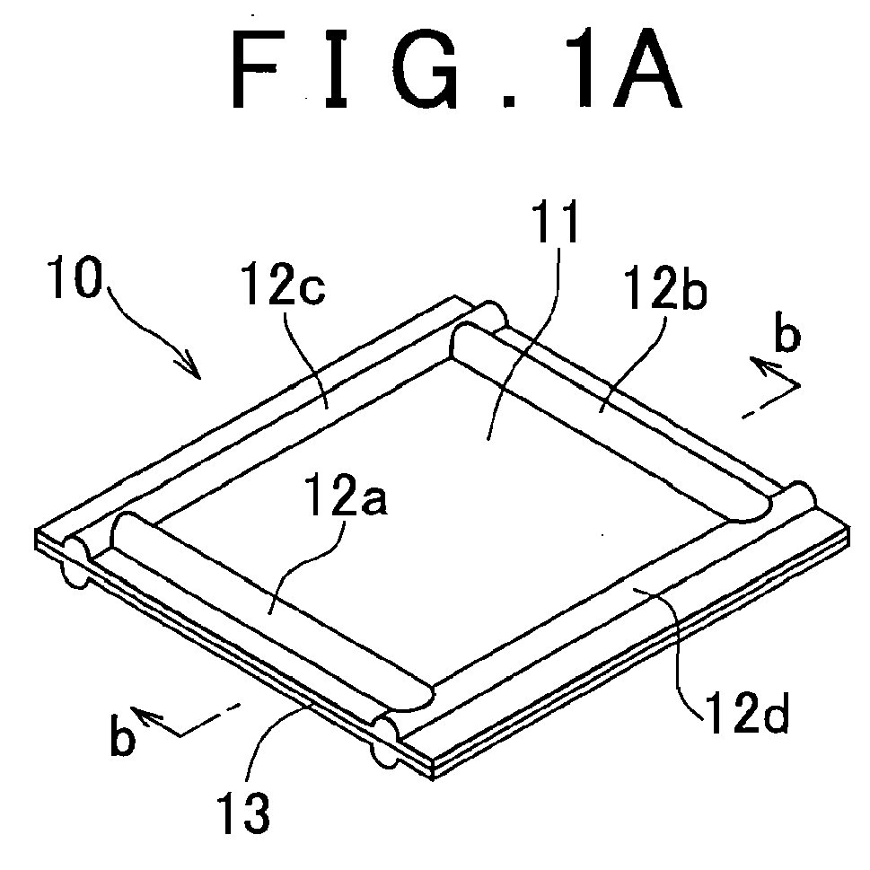
- a solid polymer electrolyte membrane 10 is rectangular as a whole.
- sealing ribs 12a to 12d made of an electrolyte resin that is the same as the electrolyte resin that forms an electrolyte membrane main body 11 are formed integrally with the two opposite surfaces of the electrolyte membrane main body 11, extending along the four side edges of the rectangular electrolyte membrane main body 11.
- the electrolyte membrane 10 has a porous reinforcement film 13, such as a stretched PTFE or the like, and is thus provided as a reinforced type electrolyte membrane.
- the porous reinforcement film 13 may be omitted.
- the sealing ribs 12 do not need to be formed along all the four side edges. For example, it is permissible that only two opposite side edges be provided with sealing ribs 12a, 12b or sealing ribs 12c, 12d.
- FIG 1C schematically shows a cross-section of a membrane-electrode assembly 20 that is made up of the electrolyte membrane 10 and gas diffusion electrodes 23a, 23b.
- An anode-side gas diffusion electrode 23a made up of a catalyst layer 21a and a gas diffusion layer 22a on the anode side is stacked on one of the two surfaces of the electrolyte membrane 10, and a cathode-side gas diffusion electrode 23b made up of a catalyst layer 21b and a gas diffusion layer 22b on the cathode side is stacked on the other surface of the solid polymer electrolyte membrane 10.
- the electrolyte membrane 10 is larger than the gas diffusion electrodes 23a, 23b, and extends further sideway from the four side end portions of the gas diffusion electrodes 23a, 23b. Then, the sealing ribs 12a to 12d are formed integrally with the extensions of the electrolyte membrane main body 11 to a height that is greater than the thickness of the gas diffusion electrodes 23a, 23b. In an ordinary solid polymer fuel cell, the height of the sealing ribs 12a to 12d is in the range of 10 ⁇ m to 500 ⁇ m.
- a fuel cell 30 is formed.
- separators 32 each having a gas channel 31 are disposed on the two opposite surfaces of the membrane-electrode assembly 20.
- a small amount of adhesive is applied to the sealing ribs 12a to 12d.
- a fuel cell 30 as shown in FIG 1E is provided.
- the fuel cell 30, whose sealing ribs 12a to 12d are formed from the same electrolyte resin as the electrolyte membrane main body 11 integrally with the electrolyte membrane main body 11, secures a high sealing characteristic.
- the resin that forms the sealing ribs may be any resin if it is a resin that can be integrated with the electrolyte membrane main body 11 when thermally melted, and does not need to be the same as the electrolyte resin that forms the electrolyte membrane main body 11.
- the resin include PFA, FEP, ETFE, PVDF, etc. which are fluorine-based resins.
- fluorine type electrolyte resin is used as an electrolyte resin.
- a fluorine type electrolyte resin particle is placed in a conventionally known resin kneading extruder device (not shown), and is heated and kneaded.
- the electrolyte resin p melted thereby is pressure-fed to a die 1 as shown in FIG 2A .
- the die 1 has a resin ejection opening 2 whose cross-sectional shape is shown in FIG 2B .
- the electrolyte resin p is extruded from the resin ejection opening 2.
- the resin ejection opening 2 has a flattened shape as a whole in which the lateral width b is greater than the vertical width d.
- Recessed grooves 3a, 3a are formed near two opposite side edges of the resin ejection opening 2 in the lateral width direction. Therefore, the molten electrolyte resin p fed into the die 1, as shown in FIG 2A , is extruded from the resin ejection opening 2 as an elongated-shape electrolyte thin film 11a having a thickness d and a lateral width b.
- each of the two surfaces of the extruded electrolyte thin film 11a has ridges 11b, 11b that are formed integrally with the surface, extending along the two side edges of the electrolyte thin film 11a, in accordance with the shape of the recessed grooves 3a, 3a formed in the resin ejection opening 2.
- the recessed grooves 3a, 3a are shown in the drawings as having a semi-circular cross-sectional shape, the cross-section thereof may have an arbitrary shape, such as a triangular shape, an elliptic shape, a rectangular shape, etc.
- the elongated-shape electrolyte thin film 11a after being cooled, is cut to a predetermined longitudinal length c into a rectangular electrolyte membrane 10a as shown in FIG 3A .
- the electrolyte thin film 11a corresponds to the electrolyte membrane main body 11
- the two ridges 11b, 11b correspond to the sealing ribs 12a, 12b.
- the two cut sides 14 of the electrolyte membrane 10a are not provided with a sealing rib, this shape of the electrolyte membrane 10a suffices for the use in fuel cells depending on the configurations of the fuel cells.
- the two cut sides 14, 14 of the electrolyte thin film 11a are, for example, rolled or bent back, to form superimposed portions 15.
- a heating die or the like at least the formed superimposed portions 15 are melted by heating.
- FIG 3C sealing ribs 16, 16 along the two cut-side sides 14, 14 of the electrolyte membrane main body 11 are formed in a state where the sealing ribs 16, 16 are integrated with the electrolyte membrane main body 11.
- FIG 3D an electrolyte membrane 10b having sealing ribs along the four sides is obtained.
- electrolyte membrane 10b corresponds to the electrolyte membrane 10 shown in FIGS. 1A and 1B from which the porous reinforcement film 13 is removed, and the corresponding portions in FIG 3D are denoted by the same reference characters as in FIG 1A .
- FIGS. 4A to 4C an example of the production method for producing an electrolyte membrane 10 that has a porous reinforcement film 13 shown in FIGS. 1A and 1B will be described with reference to FIGS. 4A to 4C .
- a die 1A having a shape as shown in FIG 4A is used.
- the die 1A has a membrane passing path 4 through which the porous reinforcement film 13 passes, and resin ejection openings 5a, 5b that are located at the two opposite surfaces of the porous reinforcement film 13 that passes through the membrane passing path 4.
- Each of the resin ejection openings 5a, 5b communicates with a corresponding one of resin supply passageways 6a, 6b.
- the resin supply passageways 6a, 6b are supplied with the thermally melted electrolyte resin p, for example, which is a fluorine type electrolyte, under a predetermined pressure from a kneading extruder device for the electrolyte resin.
- the shape of an outlet portion 7 of the membrane passing path 4 is substantially the same as the shape of the resin ejection opening 2 of the die 1 shown in FIG 2 , and specifically, has a flattened shape as a whole in which the vertical width d is greater than the lateral width b as shown in FIG 4B , and the recessed grooves 3a, 3a are formed near the two side ends in the lateral width direction.
- the molten electrolyte resin p supplied to the resin supply passageways 6a, 6b is extruded from the resin ejection openings 5a, 5b at a predetermined pressure, and impregnates the porous reinforcement film 13 from the two surface sides. Due to the extruding force created by the elasticity of the resin p, the porous reinforcement film 13 impregnated with the resin p is extruded from the outlet portion 7 of the membrane passing path 4, into an elongated shape as an electrolyte membrane main body 11c.
- the extruded reinforced type electrolyte thin film 11c has a thickness d and a lateral width b, and has a porous reinforcement film 13 inside therein, as shown in the cross-sectional view in FIG 4C .
- each of the two surfaces of the reinforced type electrolyte thin film 11c has, along the two sides thereof, ridges 11b, 11b that are integrally formed therewith.
- the ridges 11b, 11b have a shape that corresponds to the shape of the recessed grooves 3a, 3a formed in the outlet portion 7.
- the cross-sectional shape of the recessed grooves 3a, 3a may have an arbitrary shape, such as a triangular shape, an elliptic shape, a rectangular shape, etc.
- the thus-obtained elongated-shape electrolyte membrane main body 11c is subjected to substantially the same process as the process described above with reference to FIGS. 3A to 3D , so that a solid polymer electrolyte membrane 10 as shown in FIG 1A is obtained.
- an electrolyte thin film 10s shown in FIG 5A which does not have a sealing rib as described above is used as a starting material.
- the electrolyte thin film 10s may be produced by an arbitrary method, and may also have a porous reinforcement film although not shown.
- a thermally meltable resin particle pa whose particle size is preferably 10 ⁇ m or greater may be sprayed up to a predetermined thickness as shown in the perspective view and the cross-sectional view in FIG 5B .
- a plurality of gas passing openings 17 are formed in the electrolyte thin film 10s, and the thermally meltable resin particle pa is sprayed around the gas passing openings 17.
- the thermally meltable resin particle pa may instead be sprayed in a linear shape along the four sides as in the foregoing electrolyte membranes 10, 10a.
- the thermally meltable resin particle pa to be sprayed may be an arbitrary thermally meltable resin particle on condition that the resin particle is integrated with the electrolyte thin film 10s when thermally melted.
- the resin particle pa include PFA, FEP, ETFE, PVDF, etc., which are fluorine-based resins.
- the thermally meltable resin particle may be a particle of the resin that is the same as the electrolyte resin that forms the electrolyte thin film 10s.
- the sprayed thermally meltable resin particle pa is sandwiched by heating dies 9, 9 that have heating portions 9a, 9a with recessed grooves 8, and is melted by heating. Therefore, sealing ribs 12 of a predetermined height are formed from the molten resin particle pa integrally with the electrolyte thin film 10s.
- a sealing rib-equipped electrolyte membrane 10b in accordance with the invention as shown in FIG 5D is obtained.
- the height of the sealing ribs 12 is set, obviously, in accordance with the thickness of the gas diffusion electrodes that are provided when a membrane-electrode assembly is to be formed by using the electrolyte membrane 10b.
- gas diffusion electrodes 23a, 23b are stacked on the electrolyte membrane 10b shown in FIG 5D to form a membrane-electrode assembly 30.
- FIGS. 6A to 6D show a further embodiment of the production method for an electrolyte membrane in accordance with the invention.
- This embodiment is an improved form from the first embodiment of the method of producing an electrolyte membrane which has been described with reference to FIG 2 .
- a process is repeated in which a resin ejection opening 2 of the die 1 is expanded to a predetermined width as shown in FIG 6B at a predetermined timing and, after a predetermined amount of time, the die 1 is returned to the previous opening width.
- a region 11d with an increased thickness which corresponds to the duration of the width expansion of the resin ejection opening 2 is formed in the direction of the lateral width direction of the extruded electrolyte thin film 11a.
- the two protruded ridges 11b, 11b based on the recessed grooves 3a, 3a formed in the die 1 are formed integrally with each of the two surfaces of the elongated-shape electrolyte thin film 11a, extending in the lengthwise direction of the electrolyte thin film 11a.
- the thickened regions 11d extending in the direction of the width of the electrolyte thin film 11a and having a height and a width that correspond to the expanded opening width and the expansion time of the die 1 can be formed at predetermined intervals.
- an electrolyte membrane 10b having a shape as shown in FIG 6D can be obtained.
- the members in FIG 6D corresponding to those in FIG 1A are denoted by the same reference characters as in FIG 1A .
- FIGS. 7A to 7C further show two more embodiments of the production method for an electrolyte membrane in accordance with the invention.
- an electrolyte membrane having a substantially uniform membrane thickness over the entire membrane is created as a pre-forming by a conventionally known method, and a portion of the electrolyte membrane excluding portions where at least sealing ribs should be formed is hot-pressed at a temperature higher than or equal to the softening point of the electrolyte membrane, so that the membrane thickness is reduced by about an amount that corresponds to the thickness of the gas diffusion electrodes.
- gas diffusion electrodes are formed on the regions in which the membrane thickness of the electrolyte membrane has been reduced.
- the portions of the electrolyte membrane having a relatively great thickness and surrounding the thickness-reduced regions perform the function as a sealing rib.
- an electrolyte thin film (pre-forming) 10s having a substantially uniform membrane thickness of about 10 ⁇ m to about 100 ⁇ m and not provided with a sealing rib is formed from, for example, a side chain terminal group-SO 2 F type electrolyte precursor resin.
- a heating press machine 40 having upper and lower heat plates 41, 41, the electrolyte thin film 10s, excluding the peripheral portions, is hot-pressed at a temperature higher than or equal to the softening point of the electrolyte resin. Therefore, as shown in FIG 7B , an electrolyte membrane 10 is obtained in which the hot-pressed portions form a thin-walled electrolyte membrane main body portion 11, and the peripheral portions form sealing ribs 12 with a maintained thickness.
- the electrolyte membrane main body portion 11 is subjected to a hydrolysis process, whereby side chain terminal groups are substituted from -SO 2 F to -SO 2 H.
- gas diffusion electrodes (not shown) are formed, so as to form a membrane-electrode assembly. Since the regions of peripheral sealing ribs 12 are relatively thick and remain as being made of the precursor resin, an electrolyte membrane with a great strength, which sufficiently withstands the stress that is likely to concentrate around the electrodes, is obtained.
- FIG 7C shows another embodiment of the forming method.
- a belt-like electrolyte thin film 10s whose thickness is substantially uniform is prepared as a pre-forming beforehand, and the pre-forming is passed between a pair of upper and lower heated rolls 44, 44 that are provided with a protruded portion 43 having the shape of an electrode.
- regions with a reduced thickness are continually formed by rolling on each of the obverse and reverse sides of the belt-like electrolyte thin film (pre-forming) 10s, and the peripheral portions are left as sealing ribs 12 whose thickness is maintained.
- a porous reinforcement film-equipped electrolyte membrane may also be used as an electrolyte thin film (pre-forming) 10s.
Landscapes
- Engineering & Computer Science (AREA)
- Manufacturing & Machinery (AREA)
- Chemical & Material Sciences (AREA)
- Life Sciences & Earth Sciences (AREA)
- Sustainable Development (AREA)
- Sustainable Energy (AREA)
- Chemical Kinetics & Catalysis (AREA)
- Electrochemistry (AREA)
- General Chemical & Material Sciences (AREA)
- Composite Materials (AREA)
- Fuel Cell (AREA)
- Extrusion Moulding Of Plastics Or The Like (AREA)
Abstract


Description
- The invention relates to an electrolyte membrane for a solid polymer fuel cell, and a production method for the electrolyte membrane, and also relates to a membrane-electrode assembly and a fuel cell that include the electrolyte membrane.
- Solid polymer type fuel cell batteries are known as a form of fuel cell batteries. The solid polymer type fuel cell battery, as compared with other forms of fuel cell batteries, is low in operation temperature (about 80°C to 100°C), and allows cost reduction and compact design, and is therefore regarded as a promising motive power source of a motor vehicle or the like.
- In a solid polymer type fuel cell battery, as shown in
FIG 8 , a membrane-electrode assembly (MEA) 50, a main component element, is sandwiched byseparators fuel cell 52 that is called unit cell. The membrane-electrode assembly 50 has a structure in which an anode-sidegas diffusion electrode 58a made up of acatalyst layer 56a and agas diffusion layer 57a on the anode side is stacked on one side of a solidpolymer electrolyte membrane 55 that is an ion exchange membrane, and a cathode-sidegas diffusion electrode 58b made up of acatalyst layer 56b and agas diffusion layer 57b on the cathode side is stacked on the other side of the solidpolymer electrolyte membrane 55. - In the
unit cell 52, it is necessary to secure a gas channel between thegas diffusion electrodes separators 51 and prevent the leakage of gas to the outside of the cell and the mixture of the fuel gas and the oxidant gas. The stacking of thegas diffusion electrodes electrolyte membrane 55 forms a stepped surface in the membrane-electrode assembly 50. Therefore, when the membrane-electrode assembly 50 is sandwiched byseparators 51 to form afuel cell 52, a gap that is formed due to the step needs to be sealed. In ordinary cases, therefore, a sealing-purpose resin material 59 is applied onto the surfaces of theelectrolyte membrane 55 extending out from an end side of thegas diffusion electrodes rein material 59 reaches theseparators 51. Then, theresin material 59 is hardened by heating to form a seal portion, thereby securing a sealing characteristic. - Another technology of sealing the gap caused by the aforementioned step in the
fuel cell 52 is disclosed in the Japanese Patent Application Publication No.JP-A-2006-4677 FIG 9 , aseal member 59a made of a rubber-like elastomer or the like which has aprotrusion 59b is provided so as to cover aportion 55a of theelectrolyte membrane 55 which extends sideway from the end portions of thegas diffusion electrodes electrolyte membrane 55. When the membrane-electrode assembly 50 is sandwiched byseparators 51 to form afuel cell 52, theprotrusion 59b enters, in a pressed contact fashion, arecess portion 51a formed in aseparator 51. - Incidentally, the electrolyte membrane used in the solid polymer fuel cell is mainly a thin film of perfluorosulfonic acid polymer (Nafion, by DuPont, USA), that is, an electrolyte resin (ion exchange resin). Besides, a thin film made of an electrolyte resin alone does not achieve sufficient strength. Therefore, a technology described in Japanese Patent Application Publication No.
JP-A-9-194609 - As described above, in order to seal the gaps between the electrolyte membranes and the separators which are formed as a result of the steps formed on membrane-electrode assemblies, the fuel cells of the related-art technology adopt either the application of a seal material or member, that is, a separate material, onto the edge portion of the electrolyte membrane, or the covering of the edge portion of the electrolyte membrane with a seal member that is made of a separate material. In the method in which a seal material is applied and is hardened by heating, non-uniform application of the seal material is likely to allow leakage, or the requirement of long-time heating or hardening by heating results in damages to the membrane-electrode assembly. Furthermore, non-uniform heat-hardening of the seal material also leads to leakage.
- In the case of seal means in which a seal member made of a rubber-like elastomer or the like is provided to cover the edge portion of the electrolyte membrane, the production thereof is not easy, although high sealing effect can be expected due to the pressed contact of the seal member to the separator side. Furthermore, there is an inconvenience of the seal member being liable to positional deviation.
- Furthermore, in either one of the related-art sealing technology in the fuel cells, a material different from the electrolyte membrane is interposed between the electrolyte membrane and the separators, and therefore a boundary surface is inevitably formed between the electrolyte membrane and the seal member, and there is a risk of the boundary surface causing breakage of seal.
- It is an object of the invention to provide an electrolyte membrane in a fuel cell in which a gap formed between a separator and the electrolyte membrane that form a membrane-electrode assembly can be more completely sealed, and a production method for the electrolyte membrane. It is another object of the invention to provide a membrane-electrode assembly and a fuel cell that incorporate the electrolyte membrane.
- An electrolyte membrane in accordance with a first aspect of the invention is an electrolyte membrane for a solid polymer fuel cell, and basically characterized in that a sealing rib of a predetermined height made of an electrolyte resin or a resin integratable with the electrolyte membrane is formed integrally with the electrolyte membrane. The electrolyte membrane may be a reinforced type electrolyte membrane that includes a porous reinforcement film. The height of the sealing ribs is set in accordance with the thickness of the gas diffusion electrodes that are to be combined with the electrolyte membrane to form a membrane-electrode assembly. The height is within the range of 10 µm to 500 µm in the case of a membrane-electrode assembly for use in an ordinary solid polymer type fuel cell.
- The electrolyte resin that forms the electrolyte membrane may be an electrolyte resin that is used in the related art. In the case where a production method described later is adopted, the electrolyte resin may be a fluorine type electrolyte resin that does not thermally degrade. In that case, the produced electrolyte membrane is subjected to a process of giving ion exchange characteristic to an electrolyte polymer by a hydrolysis process or the like, thus obtaining an electrolyte membrane.
- In the electrolyte membrane according to the first aspect of the invention, the sealing ribs are formed integrally with the electrolyte membrane main body without a boundary surface, and therefore a stable sealing characteristic therebetween can be secured.
- A second aspect of the invention relates to a membrane-electrode assembly that includes an electrolyte membrane according to the first aspect, and gas diffusion electrodes stacked on two surfaces of the electrolyte membrane. The electrolyte membrane is formed so as to be larger than the gas diffusion electrodes, and has an extension portion that extends sideway from end portions of the gas diffusion electrodes. The sealing ribs of the predetermined height are formed integrally with the extension portion of the electrolyte membrane so that the predetermined height is greater than a thickness of the gas diffusion electrodes.
- A third aspect of the invention relates to a fuel cell including the membrane-electrode assembly according to the second aspect, and separators sandwiching the membrane-electrode assembly, the fuel cell being characterized in that top portions of the sealing ribs formed integrally with the electrolyte membrane contact the separators.
- In the membrane-electrode assembly and the fuel cell described above, high sealing characteristic can be secured, and therefore the leakage of gas to the outside of the fuel cell and the mixture of the fuel gas and the oxidant gas (gas cross) can be reliably restrained.
- A fourth aspect of the invention relates to a first method of producing an electrolyte membrane according to the first aspect. The production method for the electrolyte membrane includes at least the steps of forming the sealing ribs of the predetermined height made of an electrolyte resin integrally with the elongated-shape electrolyte membrane near two side edges of the elongated-shape electrolyte membrane by using a die having, near two side edges of a resin ejection opening, recessed grooves whose depth corresponds to the height of the sealing ribs, and extruding the thermally molten electrolyte resin from the resin ejection opening of the die.
- In the first production method according to the fourth aspect, a conventionally known kneading extruder device feeds the thermally molten electrolyte resin to the die, and continuously extrudes the thermally molten electrolyte resin in an elongated thin-film shape from the resin ejection opening of the die. The resin ejection opening of the die has, near its two side edges, recessed grooves whose depth corresponds to the height of the sealing ribs that are formed on the electrolyte membrane to be produced. Therefore, near the two side edges of the molten electrolyte resin extruded, protruded sealing ribs are formed integrally with the electrolyte membrane main body. As descried above, in this production method, the electrolyte resin to be used may be fluorine type electrolyte resin that does not thermally degrade. In that case, after the extrusion, the membrane is subjected to a process of giving ion exchange characteristic to an electrolyte polymer by cooling and a hydrolysis process or the like, thus obtaining an electrolyte membrane.
- A fifth aspect of the invention relates to a second production method for an electrolyte membrane. The method includes at least the step where a die having a membrane passing path through which the porous reinforcement film passes, recessed grooves which are formed near two side edges of an outlet portion of the membrane passing path and whose depth corresponds to the height of the sealing ribs, and resin ejection openings that are positioned at two surfaces of the porous reinforcement film that passes through the membrane passing path, the step where while the porous reinforcement film is being passed through the membrane passing path, thermally molten electrolyte resin is extruded from the resin ejection opening of the die so that the porous reinforcement film is impregnated with the molten electrolyte resin, and the step where when the porous reinforcement film impregnated with the resin passes through the outlet portion of the membrane passing path, the sealing ribs of the predetermined height made of the electrolyte resin are formed integrally with the resin-impregnated porous reinforcement film, near two side edges of the porous reinforcement film, so that the porous reinforcement film is extruded from the die as an elongated-shape reinforced type electrolyte membrane.
- The second production method according to the fifth aspect is a method for producing a so-called reinforced type electrolyte membrane. The electrolyte resin to be used and the method of supplying the thermally molten electrolyte resin to the die may be the same as in the first production method according to the fourth aspect of the invention. Examples of the porous reinforcement film to be used include porous reinforcement films created by stretching a PTFE (polytetrafluoroethylene), a polyolefin resin, etc., in the monoaxial direction or the biaxial directions. The thickness thereof may be about 5 µm to about 50 µm.
- In the second production method according to the fifth aspect, too, the electrolyte membrane including the porous reinforcement film which is extruded from the die has, near its two side edges, protruded sealing ribs that are formed integrally with the electrolyte membrane main body. As described above, in this production method, too, the electrolyte resin to be used may be a fluorine type electrolyte resin that does not thermally degrade. In that case, after the extrusion, the membrane is subjected to a process of giving ion exchange characteristic to an electrolyte polymer by cooling and a hydrolysis process or the like, thus obtaining a reinforced type electrolyte membrane.
- In any of the foregoing production methods, an elongated-shape electrolyte membrane in which sealing ribs are formed integrally with the electrolyte membrane near the two side edges thereof is obtained.
- If the electrolyte membrane is actually used as electrolyte membranes for fuel cells, the elongated-shape electrolyte membrane is cut to a predetermined width to provide rectangular electrolyte membranes. In that case, the two cut-side edge portions do not have sealing ribs. With respect to these two side edges, a sealing technology described in Japanese Patent Application Publication No.
JP-A-2006-4677 JP-A-9-194609 - In order to solve this, the production method for the electrolyte membrane may further include the step of cutting the produced elongated-shape electrolyte membrane provided with the sealing ribs of the predetermined height made of the electrolyte resin which are formed integrally with the electrolyte membrane near the two side edges of the electrolyte membrane, into a rectangular electrolyte membrane with a predetermined width, the step of forming superimposed portions along two side edges of the rectangular electrolyte membrane along which a sealing rib is not formed integrally with the electrolyte membrane, and the step of forming the electrolyte resin-made sealing ribs of the predetermined height integrally with the electrolyte membrane by melting at least the superimposed portions by, for example, sandwiching it between heating dies.
- Therefore, the step of forming the superimposed portions can be performed by a technique of, for example, bending or rolling back the side edge portions that do not have a sealing rib. The electrolyte resin of the portions having an increased thickness due to the superimposition is melted by, for example, sandwiching the portions between heating dies. As a result, sealing ribs corresponding in shape to the recessed grooves formed on the heating dies are formed integrally with the electrolyte membrane main body. After that, by performing a hydrolysis process of the like, if needed, an electrolyte membrane whose four side edges are provided with electrolyte resin-made sealing ribs that are formed integrally with the electrolyte membrane main body is obtained. The shape of the recessed grooves formed on the heating dies is set as appropriate, in accordance with the shape of the sealing ribs required for the side edges.
- A sixth aspect of the invention relates to still another production method for an electrolyte membrane. The production method includes at least the step where an electrolyte membrane that does not have a sealing rib is created, the step where a resin particle integratable with the electrolyte membrane when melted or an electrolyte resin particle is sprayed to sites on the created electrolyte membrane where the sealing ribs are to be formed, and the step in which the sealing ribs of the predetermined height made of the resin particle or electrolyte resin is formed integrally with the electrolyte membrane by thermally melting the resin particle or the electrolyte resin particle sprayed to the electrolyte membrane.
- In the production method according to the sixth aspect, the starting material is a conventionally used electrolyte membrane that does not have a sealing rib. This production method for the electrolyte membrane is arbitrary, and is free of restriction. For example, the electrolyte membrane may be a flat electrolyte membrane obtained by extruding a molten electrolyte resin from a die. Furthermore, the electrolyte membrane may also be a reinforced type electrolyte membrane that includes a porous reinforcement film.
- An electrolyte resin particle or a resin particle integratable with the electrolyte membrane when melted is sprayed to sites on the electrolyte membrane where the sealing ribs are to be formed. Examples of the resin particle integratable with the electrolyte membrane when melted include PFA, FEP, ETFE, PVDF, etc., which are fluorine-based resins. The electrolyte resin particle to be sprayed may be an arbitrary electrolyte resin particle on condition that the resin particle is integratable with the electrolyte membrane main body when thermally melted. For example, the electrolyte resin particle may be a particle of the resin that is the same as the electrolyte resin that forms the electrolyte membrane main body. In view of operability, the particle diameter of the resin particle may be 10 µm or greater.
- The sprayed resin particle or the sprayed electrolyte resin particle is thermally melted by, for example, sandwiching it between heating dies, sealing ribs of a predetermined height are formed integrally with the electrolyte membrane. In this case, too, the height of the sealing ribs is set in accordance with the thickness of the gas diffusion electrodes that are provided to be combined with the electrolyte membrane to form a membrane-electrode assembly. In the case of a membrane-electrode assembly used in ordinary solid polymer fuel cells, the height of the sealing ribs is within the range of 10 µm to 500 µm.
- Incidentally, this production method may be applied to an electrolyte membrane that is a single membrane. In that case, a membrane-electrode assembly is formed by forming gas diffusion electrodes on the electrolyte membrane provided with sealing ribs formed integrally therewith. Besides, this production method may also be applied to an electrolyte membrane that extends sideway from end portions of the gas diffusion electrodes of the membrane-electrode assembly that is formed beforehand. In any case, the resin particle is subjected to a thermally melting process, and therefore, a fluorine type electrolyte resin particle that does not thermally degrade may be used. In that case, the electrolyte membrane (or membrane-electrode assembly) provided with sealing ribs formed integrally therewith is subjected to a process of giving ion exchange characteristic to an electrolyte polymer by a hydrolysis process or the like.
- A seventh aspect of the invention relates to a further production method for an electrolyte membrane. The method includes at least the step where an electrolyte membrane that does not have a sealing rib is created, and the step where a portion of the created electrolyte membrane obtained by excluding a portion where the sealing rib is to be created is pressed at a temperature that is higher than or equal to a softening point of the electrolyte membrane. According to this production method, an electrolyte membrane provided with sealing ribs of a predetermined height formed integrally therewith can be obtained by simpler steps. The regions to be pressed may be only a region where the gas diffusion electrodes are formed when the pressed electrolyte membrane is used to form a membrane-electrode assembly. In that case, recessed portions may be formed on the two surfaces of the electrolyte membrane by pressing the electrolyte membrane so that the recessed portions have a depth substantially equal to the thickness of the gas diffusion electrodes.
- According to the invention, an electrolyte membrane and a membrane-electrode assembly that are able to improve the sealing characteristic of a cell when used to form a fuel cell is obtained. Furthermore, a fuel cell with improved sealing characteristic is obtained.
- The foregoing and further objects, features and advantages of the invention will become apparent from the following description of example embodiments with reference to the accompanying drawings, wherein like numerals are used to represent like elements and wherein:
-
FIG 1A is a diagram schematically showing an embodiment of an electrolyte membrane in accordance with the invention; -
FIG 1B is a cross-sectional view taken along line b-b ofFIG 1A ; -
FIG 1C is a cross-sectional view schematically showing an embodiment of a membrane-electrode assembly in accordance with the invention; -
FIG 1D is a schematic cross-sectional view showing a process of producing an embodiment of a fuel cell in accordance with the invention; -
FIG 1E is a cross-sectional view schematically showing a fuel cell after the production process; -
FIGS. 2A to 2C are diagrams schematically showing a first embodiment of a method of producing an electrolyte membrane in accordance with the invention, andFIG 2A shows a state where an electrolyte thin film is extruded from a die so as to have an elongated shape, andFIG 2B shows a resin ejection opening of the die in a sectional view, andFIG 2C is a cross-sectional view taken on line c-c ofFIG 2A , showing an extruded electrolyte thin film; -
FIGS. 3A to 3D show processes performed on the electrolyte membrane obtained by the method shown inFIGS. 2A to 2C , andFIG 3A shows an electrolyte membrane cut to a predetermined width, andFIG 3B shows a state where a superimposed portion is formed at a side edge portion, andFIG 3C shows a state of electrolyte membrane after the superimposed portions have been melted by heating, andFIG 3D shows an electrolyte membrane after the working process; -
FIGS. 4A to 4C are diagrams schematically illustrating a second embodiment of a method of producing an electrolyte membrane in accordance with the invention, andFIG 4A shows a state where a reinforced type electrolyte thin film is extruded from a die, in an elongated shape, andFIG 4B shows a membrane passing path outlet portion of the die in a cross-section, andFIG 4C shows an extruded electrolyte thin film in a cross-section; -
FIGS. 5A to 5D are diagrams schematically illustrating a third embodiment of a method of producing an electrolyte membrane in accordance with the invention, each showing a production process; -
FIGS. 6A to 6D are diagrams schematically illustrating a further embodiment of a method of producing an electrolyte membrane in accordance with the invention, andFIGS. 6A to 6C illustrate the production processes, andFIG 6D shows an electrolyte membrane obtained; -
FIGS. 7A to 7C are diagrams schematically illustrating two more embodiments of a method producing an electrolyte membrane in accordance with the invention, andFIG 7A schematically illustrate an embodiment that employs a heating press machine, andFIG 7C schematically shows an embodiment that uses a roll press; -
FIG 8 is a schematic cross-sectional view showing an example of related-art fuel cells; and -
FIG 9 is a schematic cross-sectional view showing another example of the related-art fuel cell. - Embodiments of the invention will be described hereinafter with reference to the drawings.
FIGS. 1A and 1B are diagrams schematically showing an embodiment of the electrolyte membrane in accordance with the invention, andFIG 1C is a diagram schematically showing an embodiment of the membrane-electrode assembly in accordance with the invention, andFIGS. 1D and 1E are diagrams schematically showing a cross-section of an embodiment of the fuel cell in accordance with the invention.FIGS. 2A to 2C andFIGS. 3A to 3D are diagrams schematically illustrating a first embodiment of the method of producing an electrolyte membrane in accordance with the invention.FIGS. 4A to 4C are diagrams schematically illustrating a second embodiment of the method of producing an electrolyte membrane in accordance with the invention.FIGS. 5A to 5D are diagrams schematically illustrating a third embodiment of the method of producing an electrolyte membrane in accordance with the invention.FIGS. 6A to 6D andFIGS. 7A to 7C are diagrams schematically illustrating still further embodiments of the method of producing an electrolyte membrane in accordance with the invention. - As shown in a perspective view in
FIG. 1A and a cross-sectional view inFIG 1B taken on line b-bFIG 1A , a solidpolymer electrolyte membrane 10 is rectangular as a whole. In the solidpolymer electrolyte membrane 10, sealingribs 12a to 12d made of an electrolyte resin that is the same as the electrolyte resin that forms an electrolyte membranemain body 11 are formed integrally with the two opposite surfaces of the electrolyte membranemain body 11, extending along the four side edges of the rectangular electrolyte membranemain body 11. Besides, in this embodiment, theelectrolyte membrane 10 has aporous reinforcement film 13, such as a stretched PTFE or the like, and is thus provided as a reinforced type electrolyte membrane. Theporous reinforcement film 13 may be omitted. Furthermore, the sealingribs 12 do not need to be formed along all the four side edges. For example, it is permissible that only two opposite side edges be provided with sealingribs ribs -
FIG 1C schematically shows a cross-section of a membrane-electrode assembly 20 that is made up of theelectrolyte membrane 10 andgas diffusion electrodes gas diffusion electrode 23a made up of acatalyst layer 21a and agas diffusion layer 22a on the anode side is stacked on one of the two surfaces of theelectrolyte membrane 10, and a cathode-sidegas diffusion electrode 23b made up of acatalyst layer 21b and agas diffusion layer 22b on the cathode side is stacked on the other surface of the solidpolymer electrolyte membrane 10. Theelectrolyte membrane 10 is larger than thegas diffusion electrodes gas diffusion electrodes ribs 12a to 12d are formed integrally with the extensions of the electrolyte membranemain body 11 to a height that is greater than the thickness of thegas diffusion electrodes ribs 12a to 12d is in the range of 10 µm to 500 µm. - Using the membrane-
electrode assembly 20 shown inFIG 1C , a fuel cell 30 is formed. As shown inFIG 1D ,separators 32 each having agas channel 31 are disposed on the two opposite surfaces of the membrane-electrode assembly 20. In accordance with needs, a small amount of adhesive is applied to the sealingribs 12a to 12d. Through the pressure welding of the membrane-electrode assembly 20 and theseparators 32 under overall pressurization, a fuel cell 30 as shown inFIG 1E is provided. As described above, the fuel cell 30, whose sealingribs 12a to 12d are formed from the same electrolyte resin as the electrolyte membranemain body 11 integrally with the electrolyte membranemain body 11, secures a high sealing characteristic. In addition, the resin that forms the sealing ribs may be any resin if it is a resin that can be integrated with the electrolyte membranemain body 11 when thermally melted, and does not need to be the same as the electrolyte resin that forms the electrolyte membranemain body 11. Examples of the resin include PFA, FEP, ETFE, PVDF, etc. which are fluorine-based resins. - Next, an embodiment of the method of producing an electrolyte membrane in accordance with the invention will be described with reference to
FIGS. 2A to 2C and 3A to 3D . In this production method, fluorine type electrolyte resin is used as an electrolyte resin. A fluorine type electrolyte resin particle is placed in a conventionally known resin kneading extruder device (not shown), and is heated and kneaded. The electrolyte resin p melted thereby is pressure-fed to adie 1 as shown inFIG 2A . Thedie 1 has a resin ejection opening 2 whose cross-sectional shape is shown inFIG 2B . The electrolyte resin p is extruded from theresin ejection opening 2. - As shown in
FIG 2B , theresin ejection opening 2 has a flattened shape as a whole in which the lateral width b is greater than the vertical width d. Recessedgrooves die 1, as shown inFIG 2A , is extruded from the resin ejection opening 2 as an elongated-shape electrolytethin film 11a having a thickness d and a lateral width b. As shown in the cross-sectional view inFIG 2C taken on line c-c ofFIG 2A , each of the two surfaces of the extruded electrolytethin film 11a hasridges thin film 11a, in accordance with the shape of the recessedgrooves resin ejection opening 2. Incidentally, although the recessedgrooves - The elongated-shape electrolyte
thin film 11a, after being cooled, is cut to a predetermined longitudinal length c into arectangular electrolyte membrane 10a as shown inFIG 3A . In the comparison between theelectrolyte membrane 10a and theelectrolyte membrane 10 shown inFIGS. 1A and 1B , the electrolytethin film 11a corresponds to the electrolyte membranemain body 11, and the tworidges ribs sides 14 of theelectrolyte membrane 10a are not provided with a sealing rib, this shape of theelectrolyte membrane 10a suffices for the use in fuel cells depending on the configurations of the fuel cells. - To obtain an electrolyte membrane having sealing ribs along the four side edges as in the
electrolyte membrane 10 shown inFIGS. 1A and 1B , the two cutsides thin film 11a are, for example, rolled or bent back, to form superimposedportions 15. Next, using a heating die or the like, at least the formedsuperimposed portions 15 are melted by heating. As a result, as shown inFIG 3C , sealingribs side sides main body 11 are formed in a state where the sealingribs main body 11. Thus, as shown inFIG 3D , anelectrolyte membrane 10b having sealing ribs along the four sides is obtained. In addition, theelectrolyte membrane 10b corresponds to theelectrolyte membrane 10 shown inFIGS. 1A and 1B from which theporous reinforcement film 13 is removed, and the corresponding portions inFIG 3D are denoted by the same reference characters as inFIG 1A . - Next, an example of the production method for producing an
electrolyte membrane 10 that has aporous reinforcement film 13 shown inFIGS. 1A and 1B will be described with reference toFIGS. 4A to 4C . In this method, adie 1A having a shape as shown inFIG 4A is used. Thedie 1A has amembrane passing path 4 through which theporous reinforcement film 13 passes, andresin ejection openings porous reinforcement film 13 that passes through themembrane passing path 4. Each of theresin ejection openings resin supply passageways resin supply passageways outlet portion 7 of themembrane passing path 4 is substantially the same as the shape of the resin ejection opening 2 of thedie 1 shown inFIG 2 , and specifically, has a flattened shape as a whole in which the vertical width d is greater than the lateral width b as shown inFIG 4B , and the recessedgrooves - The molten electrolyte resin p supplied to the
resin supply passageways resin ejection openings porous reinforcement film 13 from the two surface sides. Due to the extruding force created by the elasticity of the resin p, theporous reinforcement film 13 impregnated with the resin p is extruded from theoutlet portion 7 of themembrane passing path 4, into an elongated shape as an electrolyte membranemain body 11c. The extruded reinforced type electrolytethin film 11c has a thickness d and a lateral width b, and has aporous reinforcement film 13 inside therein, as shown in the cross-sectional view inFIG 4C . Besides, each of the two surfaces of the reinforced type electrolytethin film 11c has, along the two sides thereof,ridges ridges grooves outlet portion 7. Incidentally, in this case, too, the cross-sectional shape of the recessedgrooves main body 11c is subjected to substantially the same process as the process described above with reference toFIGS. 3A to 3D , so that a solidpolymer electrolyte membrane 10 as shown inFIG 1A is obtained. - Next, a third embodiment of the method of producing an electrolyte membrane in accordance with the invention will be described with reference to
FIGS. 5A to 5D . In this embodiment, an electrolytethin film 10s shown inFIG 5A which does not have a sealing rib as described above is used as a starting material. The electrolytethin film 10s may be produced by an arbitrary method, and may also have a porous reinforcement film although not shown. At sites on the electrolytethin film 10s where the sealingribs 12 should be formed, a thermally meltable resin particle pa whose particle size is preferably 10 µm or greater may be sprayed up to a predetermined thickness as shown in the perspective view and the cross-sectional view inFIG 5B . In the construction shown inFIGS. 5A to 5D , a plurality ofgas passing openings 17 are formed in the electrolytethin film 10s, and the thermally meltable resin particle pa is sprayed around thegas passing openings 17. However, the thermally meltable resin particle pa may instead be sprayed in a linear shape along the four sides as in the foregoingelectrolyte membranes thin film 10s when thermally melted. Examples of the resin particle pa include PFA, FEP, ETFE, PVDF, etc., which are fluorine-based resins. The thermally meltable resin particle may be a particle of the resin that is the same as the electrolyte resin that forms the electrolytethin film 10s. - Next, as shown in
FIG 5C , the sprayed thermally meltable resin particle pa is sandwiched by heating dies 9, 9 that haveheating portions grooves 8, and is melted by heating. Therefore, sealingribs 12 of a predetermined height are formed from the molten resin particle pa integrally with the electrolytethin film 10s. Thus, a sealing rib-equippedelectrolyte membrane 10b in accordance with the invention as shown inFIG 5D is obtained. In this case, too, the height of the sealingribs 12 is set, obviously, in accordance with the thickness of the gas diffusion electrodes that are provided when a membrane-electrode assembly is to be formed by using theelectrolyte membrane 10b. - Although not shown,
gas diffusion electrodes electrolyte membrane 10b shown inFIG 5D to form a membrane-electrode assembly 30. Besides, it is also permissible to form a membrane-electrode assembly 20 in whichgas diffusion electrodes thin film 10s (seeFIG 1 ) beforehand, to spray an electrolyte resin particle pa to necessary sites in the regions of theelectrolyte membrane 10a which extend sideways from the end portions of the gas diffusion electrodes, and to perform thermally melting process. -
FIGS. 6A to 6D show a further embodiment of the production method for an electrolyte membrane in accordance with the invention. This embodiment is an improved form from the first embodiment of the method of producing an electrolyte membrane which has been described with reference toFIG 2 . Specifically, during a process of extruding an electrolytethin film 11a into an elongated shape through the use of adie 1 as shown inFIG 6A , a process is repeated in which a resin ejection opening 2 of thedie 1 is expanded to a predetermined width as shown inFIG 6B at a predetermined timing and, after a predetermined amount of time, thedie 1 is returned to the previous opening width. As a result, as shown inFIG 6C , aregion 11d with an increased thickness which corresponds to the duration of the width expansion of theresin ejection opening 2 is formed in the direction of the lateral width direction of the extruded electrolytethin film 11a. - According to this method, the two protruded
ridges grooves die 1 are formed integrally with each of the two surfaces of the elongated-shape electrolytethin film 11a, extending in the lengthwise direction of the electrolytethin film 11a. Simultaneously, the thickenedregions 11d extending in the direction of the width of the electrolytethin film 11a and having a height and a width that correspond to the expanded opening width and the expansion time of thedie 1 can be formed at predetermined intervals. Therefore, merely by cutting the obtained elongated-shape electrolytethin film 11a at a predetermined site, anelectrolyte membrane 10b having a shape as shown inFIG 6D can be obtained. In addition, the members inFIG 6D corresponding to those inFIG 1A are denoted by the same reference characters as inFIG 1A . -
FIGS. 7A to 7C further show two more embodiments of the production method for an electrolyte membrane in accordance with the invention. In these embodiments, an electrolyte membrane having a substantially uniform membrane thickness over the entire membrane is created as a pre-forming by a conventionally known method, and a portion of the electrolyte membrane excluding portions where at least sealing ribs should be formed is hot-pressed at a temperature higher than or equal to the softening point of the electrolyte membrane, so that the membrane thickness is reduced by about an amount that corresponds to the thickness of the gas diffusion electrodes. On the regions in which the membrane thickness of the electrolyte membrane has been reduced, gas diffusion electrodes are formed. The portions of the electrolyte membrane having a relatively great thickness and surrounding the thickness-reduced regions perform the function as a sealing rib. - Specifically, for example, an electrolyte thin film (pre-forming) 10s having a substantially uniform membrane thickness of about 10 µm to about 100 µm and not provided with a sealing rib is formed from, for example, a side chain terminal group-SO2F type electrolyte precursor resin. Then, as shown in
FIG. 7A , using aheating press machine 40 having upper andlower heat plates thin film 10s, excluding the peripheral portions, is hot-pressed at a temperature higher than or equal to the softening point of the electrolyte resin. Therefore, as shown inFIG 7B , anelectrolyte membrane 10 is obtained in which the hot-pressed portions form a thin-walled electrolyte membranemain body portion 11, and the peripheral portions form sealingribs 12 with a maintained thickness. - The electrolyte membrane
main body portion 11 is subjected to a hydrolysis process, whereby side chain terminal groups are substituted from -SO2F to -SO2H. In the region of the electrolyte membranemain body 11, gas diffusion electrodes (not shown) are formed, so as to form a membrane-electrode assembly. Since the regions of peripheral sealingribs 12 are relatively thick and remain as being made of the precursor resin, an electrolyte membrane with a great strength, which sufficiently withstands the stress that is likely to concentrate around the electrodes, is obtained. -
FIG 7C shows another embodiment of the forming method. In this method, a belt-like electrolytethin film 10s whose thickness is substantially uniform is prepared as a pre-forming beforehand, and the pre-forming is passed between a pair of upper and lowerheated rolls portion 43 having the shape of an electrode. As the upper and lowerheated rolls ribs 12 whose thickness is maintained. By cutting the electrolytethin film 10s into a predetermined size, an electrolyte membrane as shown inFIG 7B is obtained. - Incidentally, in the embodiments of the production method shown in
FIGS. 7A to 7C , a porous reinforcement film-equipped electrolyte membrane may also be used as an electrolyte thin film (pre-forming) 10s. - While the invention has been described with reference to example embodiments thereof, it is to be understood that the invention is not limited to the described embodiments or constructions. To the contrary, the invention is intended to cover various modifications and equivalent arrangements. In addition, while the various elements of the example embodiments are shown in various combinations and configurations, other combinations and configurations, including more, less or only a single element, are also within the spirit and scope of the invention.
Claims (12)
- A method of producing an electrolyte membrane (10b) for a solid polymer fuel cell , wherein sealing ribs (12) of a predetermined height are formed integrally with the electrolyte membrane,
the method being characterized by comprising:creating an electrolyte membrane (10s) that does not have a sealing rib, andspraying a electrolyte resin particle or a resin particle (Pa) integratable with the electrolyte membrane (10s) when melted to sites on the created electrolyte membrane (10s) where the sealing ribs (12) are to be formed, andforming the sealing ribs (12) of the predetermined height made of the electrolyte resin particle or the resin particle (Pa) integrally with the electrolyte membrane (10s) by thermally melting the electrolyte resin particle or the resin particle (Pa) sprayed to the electrolyte membrane (10s). - The method according to claim 1, wherein, a particle diameter of the electrolyte resin particle or the resin particle (Pa) integratable with the electrolyte membrane when melted, which is sprayed is 10 µm or greater.
- A method of prodicing an electrolyte membrane (10) for a solid polymer fuel cell, wherein the electrolyte membrane (10) is provided with sealing ribs (12) of a predetermined height made of an electrolyte resin which are formed integrally with the electrolyte membrane, characterized by comprising:creating an electrolyte membrane (10s) that does not have a sealing rib, andpressing at least a portion of the created electrolyte membrane (10s) obtained by excluding a portion where the sealing rib is to be created at a temperature that is higher than or equal to a softening point of the electrolyte membrane (10s).
- An electrolyte membrane (10) for a solid polymer fuel cell, characterized in that a sealing rib (12) of a predetermined height made of a resin (Pa) integratable with the electrolyte membrane (10) when melted is formed integrally with the electrolyte membrane (10).
- An electrolyte membrane (10) for a solid polymer fuel cell, characterized in that a sealing rib (12) of a predetermined height made of an electrolyte resin is formed integrally with the electrolyte membrane (10).
- The electrolyte membrane according to claim 4 or 5, wherein
the electrolyte membrane (10) includes a porous reinforcement film as an integrated portion. - The electrolyte membrane according to any one of claims 5 to 6, wherein
the height of the sealing rib (12, 12a-12d) is within a range of 10 µm to 500 µm. - A membrane-electrode assembly (20) including:the electrolyte membrane (10) described in any one of claims 5 to 7, andgas diffusion electrodes (23a, 23b) stacked on two surfaces of the electrolyte membrane (10), characterized inthat the electrolyte membrane (10) is formed so as to be larger than the gas diffusion electrodes (23a, 23b), and has an extension portion that extends sideway from end portions of the gas diffusion electrodes (23a, 23b), andthat the sealing ribs (12, 12a-12d) of the predetermined height are formed integrally with the extension portion of the electrolyte membrane so that the predetermined height is greater than a thickness of the gas diffusion electrodes (23a, 23b).
- A fuel cell including:the membrane-electrode assembly (20) described in claim 8, andseparators (32) sandwiching the membrane-electrode assembly (20), characterized in thattop portions of the sealing ribs (12, 12a-12d) formed integrally with the electrolyte membrane (10) contact the separators.
- A method of producing an electrolyte membrane (10) for a solid polymer fuel cell,
wherein sealing ribs (12a-12d) of a predetermined height are formed integrally with the electrolyte membrane (10),
the method being characterized by comprising
forming the sealing ribs (11b) of the predetermined height made of an electrolyte resin integrally with the elongated-shape electrolyte membrane near two side edges of the elongated-shape electrolyte membrane by using a die (1) having, near two side edges of a resin ejection opening (2, 5), recessed grooves (3a) whose depth corresponds to the height of the sealing ribs (11b), and extruding the thermally molten electrolyte resin (P) from the resin ejection opening (2) of the die (1). - The method according to claim 10, wherein the electrolyte membrane (10) further includes a porous reinforcement film as an integrated portion,
the method being characterized in
that the die (1A) further has a membrane passing path (4) through which the porous reinforcement film (13) passes,
wherein the recessed grooves (3a) whose depth corresponds to the height of the sealing ribs (11b) are formed near two side edges of an outlet portion of the membrane passing path (4), and
wherein resin ejection openings (5a, 5b) are positioned at two surfaces of the porous reinforcement film (13) that passes through the membrane passing path (4),
the method including the further steps that
while the porous reinforcement film (13) is being passed through the membrane passing path (4), the thermally molten electrolyte resin (P) is extruded from the resin ejection openings (5a, 5b) of the die so that the porous reinforcement film (13) is impregnated with the molten electrolyte resin (P), and,
when the porous reinforcement film (13) impregnated with the resin passes through the outlet portion (7) of the membrane passing path (4), the sealing ribs of the predetermined height made of the electrolyte resin are formed together with the resin-impregnated porous reinforcement film (13), near two side edges of the porous reinforcement film (13), so that the porous reinforcement film (13) is extruded from the die as an elongated-shape reinforced type electrolyte membrane (11c). - The method according to claims 10 or 11, characterized by further comprising:cutting the produced elongated-shape electrolyte membrane (11a, 11c) provided with the sealing ribs (1 1b) of the predetermined height made of the electrolyte resin which are formed integrally with the electrolyte membrane near the two side edges of the electrolyte membrane, into a rectangular electrolyte membrane (10a) with a predetermined width;forming superimposed portions along two side edges of the rectangular electrolyte membrane (10a) along which a sealing rib is not formed integrally with the electrolyte membrane (10a); andforming the electrolyte resin-made sealing ribs (12a-12d) of the predetermined height integrally with the electrolyte membrane (10a) by melting at least the superimposed portions by sandwiching the superimposed portions between heating dies.
Applications Claiming Priority (2)
| Application Number | Priority Date | Filing Date | Title |
|---|---|---|---|
| JP2006236160A JP4367470B2 (en) | 2006-08-31 | 2006-08-31 | Electrolyte membrane for polymer electrolyte fuel cell, production method thereof and membrane electrode assembly |
| EP07825028.9A EP2082449B1 (en) | 2006-08-31 | 2007-08-29 | Production method for solid polymer fuel cell-purpose electrolyte membrane |
Related Parent Applications (3)
| Application Number | Title | Priority Date | Filing Date |
|---|---|---|---|
| EP07825028.9A Division EP2082449B1 (en) | 2006-08-31 | 2007-08-29 | Production method for solid polymer fuel cell-purpose electrolyte membrane |
| EP07825028.9A Division-Into EP2082449B1 (en) | 2006-08-31 | 2007-08-29 | Production method for solid polymer fuel cell-purpose electrolyte membrane |
| EP07825028.9 Division | 2007-08-29 |
Publications (2)
| Publication Number | Publication Date |
|---|---|
| EP2357698A1 true EP2357698A1 (en) | 2011-08-17 |
| EP2357698B1 EP2357698B1 (en) | 2015-09-16 |
Family
ID=38896912
Family Applications (2)
| Application Number | Title | Priority Date | Filing Date |
|---|---|---|---|
| EP07825028.9A Ceased EP2082449B1 (en) | 2006-08-31 | 2007-08-29 | Production method for solid polymer fuel cell-purpose electrolyte membrane |
| EP11166114.6A Not-in-force EP2357698B1 (en) | 2006-08-31 | 2007-08-29 | Solid polymer fuel cell-purpose electrolyte membrane, production method therefor and membrane-electrode assembly |
Family Applications Before (1)
| Application Number | Title | Priority Date | Filing Date |
|---|---|---|---|
| EP07825028.9A Ceased EP2082449B1 (en) | 2006-08-31 | 2007-08-29 | Production method for solid polymer fuel cell-purpose electrolyte membrane |
Country Status (6)
| Country | Link |
|---|---|
| US (2) | US8273498B2 (en) |
| EP (2) | EP2082449B1 (en) |
| JP (1) | JP4367470B2 (en) |
| CN (1) | CN101512805B (en) |
| CA (1) | CA2660981C (en) |
| WO (1) | WO2008029243A1 (en) |
Cited By (2)
| Publication number | Priority date | Publication date | Assignee | Title |
|---|---|---|---|---|
| WO2015145129A1 (en) * | 2014-03-24 | 2015-10-01 | Johnson Matthey Fuel Cells Limited | Membrane-seal assembly |
| WO2015145127A1 (en) * | 2014-03-24 | 2015-10-01 | Johnson Matthey Fuel Cells Limited | Process |
Families Citing this family (20)
| Publication number | Priority date | Publication date | Assignee | Title |
|---|---|---|---|---|
| JP5359341B2 (en) * | 2009-02-13 | 2013-12-04 | トヨタ自動車株式会社 | Manufacturing method of fuel cell components |
| JP5505500B2 (en) * | 2010-06-15 | 2014-05-28 | トヨタ自動車株式会社 | Fuel cell and fuel cell manufacturing method |
| CN103988351B (en) * | 2011-12-06 | 2016-06-08 | 丰田自动车株式会社 | The fuel cell |
| KR101620155B1 (en) * | 2014-01-22 | 2016-05-12 | 현대자동차주식회사 | Fuel cell and manufacturing method thereof |
| GB201515870D0 (en) * | 2015-09-08 | 2015-10-21 | Johnson Matthey Fuel Cells Ltd | Process |
| EP3472885A4 (en) * | 2016-06-15 | 2020-06-17 | 3M Innovative Properties Company | Membrane electrode assembly component and method of making an assembly |
| DE102017101276A1 (en) * | 2017-01-24 | 2018-07-26 | Audi Ag | Bipolar plate seal assembly and fuel cell stack with such |
| JP6427215B2 (en) * | 2017-03-07 | 2018-11-21 | 本田技研工業株式会社 | Method and apparatus for pressing a film molded article for polymer electrolyte fuel cell |
| CN109847974B (en) * | 2018-11-23 | 2021-07-09 | 一汽解放汽车有限公司 | A proton exchange membrane fuel cell membrane electrode spraying fixture and a method for preparing a membrane electrode using the same |
| JP7254192B2 (en) * | 2019-09-04 | 2023-04-07 | Nok株式会社 | Gasket manufacturing method |
| DE102019216876A1 (en) * | 2019-10-31 | 2021-05-06 | Robert Bosch Gmbh | Process for the production of a membrane-electrode assembly |
| DE102020207918B4 (en) | 2020-06-25 | 2023-11-16 | Vitesco Technologies GmbH | Fuel cell arrangement and method for producing a fuel cell arrangement |
| DE102020207919A1 (en) | 2020-06-25 | 2021-12-30 | Vitesco Technologies GmbH | Fuel cell assembly and method for manufacturing a fuel cell assembly |
| DE102020212103A1 (en) | 2020-09-25 | 2022-03-31 | Vitesco Technologies GmbH | Fuel cell assembly and method for manufacturing a fuel cell assembly |
| DE102020212104A1 (en) | 2020-09-25 | 2022-03-31 | Vitesco Technologies GmbH | Fuel cell assembly and method for manufacturing a fuel cell assembly |
| EP4037044A4 (en) * | 2020-09-29 | 2024-11-27 | Kolon Industries, Inc. | POLYMER ELECTROLYTE MEMBRANE, MEMBRANE-ELECTRODE UNIT AND FUEL CELL |
| DE102020212764A1 (en) | 2020-10-09 | 2022-04-14 | Vitesco Technologies GmbH | Fuel cell assembly and method for manufacturing a fuel cell assembly |
| DE102021119054A1 (en) | 2021-07-22 | 2023-01-26 | Vitesco Technologies GmbH | Device for holding a plate-shaped component when testing and/or processing the component, and use therefor |
| DE102021119029A1 (en) | 2021-07-22 | 2023-01-26 | Vitesco Technologies GmbH | Metallic bipolar plate for a fuel cell and method for producing such a bipolar plate |
| DE102021214297B4 (en) | 2021-12-14 | 2023-08-17 | Vitesco Technologies GmbH | Bipolar plate for a fuel cell stack |
Citations (7)
| Publication number | Priority date | Publication date | Assignee | Title |
|---|---|---|---|---|
| JPH09194609A (en) | 1996-01-25 | 1997-07-29 | Sumitomo Electric Ind Ltd | Ion exchange membrane and method for producing the same |
| EP1156546A1 (en) * | 1997-07-16 | 2001-11-21 | Ballard Power Systems Inc. | Method of making a resilient seal for membrane electrode assembly (MEA) in an electrochemical fuel cell |
| US20020034670A1 (en) * | 2000-07-19 | 2002-03-21 | Toshihiko Suenaga | Seal for fuel cell and forming method therefor |
| EP1255315A1 (en) * | 2000-02-08 | 2002-11-06 | Matsushita Electric Industrial Co., Ltd. | Polymer electrolyte fuel cell |
| EP1302996A2 (en) * | 2001-10-16 | 2003-04-16 | Matsushita Electric Industrial Co., Ltd. | Polymer electrolyte fuel cell |
| EP1608033A2 (en) * | 2004-06-15 | 2005-12-21 | Carl Freudenberg KG | Substrate with integrated seal |
| JP2006004677A (en) | 2004-06-15 | 2006-01-05 | Toshiba Fuel Cell Power Systems Corp | Fuel cell |
Family Cites Families (12)
| Publication number | Priority date | Publication date | Assignee | Title |
|---|---|---|---|---|
| JPH0629032A (en) | 1992-07-08 | 1994-02-04 | Sumitomo Electric Ind Ltd | High polymer electrolyte film and its manufacture |
| JPH09283163A (en) | 1996-04-11 | 1997-10-31 | Tanaka Kikinzoku Kogyo Kk | Electrolyte membrane for polymer electrolyte fuel cell, manufacturing method thereof, and gas sealing method for electrolyte membrane to electrode portion of fuel cell |
| JP2000243413A (en) * | 1999-02-23 | 2000-09-08 | Sanyo Electric Co Ltd | Electrolyte film for solid polymer fuel cell and solid polymer fuel cell using same |
| JP2001185163A (en) * | 1999-12-28 | 2001-07-06 | Asahi Glass Co Ltd | Method for producing gas diffusion electrode for solid polymer electrolyte fuel cell |
| JP4907773B2 (en) | 2001-02-07 | 2012-04-04 | 旭化成イーマテリアルズ株式会社 | Fluorine ion exchange membrane manufacturing method |
| JP4600632B2 (en) | 2001-08-24 | 2010-12-15 | Nok株式会社 | Fuel cell components |
| JP2004119269A (en) | 2002-09-27 | 2004-04-15 | Toyota Motor Corp | Electrolyte membrane for fuel cell and method for producing the same |
| EP1654776B1 (en) * | 2003-07-14 | 2013-09-11 | Umicore AG & Co. KG | Membrane electrode assembly for use in electrochemical devices |
| JP2005085594A (en) | 2003-09-09 | 2005-03-31 | Fuji Electric Holdings Co Ltd | Solid polymer electrolyte fuel cell and method for producing the same |
| JP4575658B2 (en) | 2003-11-28 | 2010-11-04 | トヨタ自動車株式会社 | Ion exchange membrane manufacturing apparatus and manufacturing method |
| JP2005243293A (en) | 2004-02-24 | 2005-09-08 | Nissan Motor Co Ltd | Solid polymer electrolyte membranes for fuel cells |
| JP4736787B2 (en) | 2005-12-20 | 2011-07-27 | トヨタ自動車株式会社 | Membrane electrode assembly and method for producing reinforced electrolyte membrane in polymer electrolyte fuel cell |
-
2006
- 2006-08-31 JP JP2006236160A patent/JP4367470B2/en not_active Expired - Fee Related
-
2007
- 2007-08-29 EP EP07825028.9A patent/EP2082449B1/en not_active Ceased
- 2007-08-29 US US12/438,012 patent/US8273498B2/en not_active Expired - Fee Related
- 2007-08-29 EP EP11166114.6A patent/EP2357698B1/en not_active Not-in-force
- 2007-08-29 CA CA2660981A patent/CA2660981C/en not_active Expired - Fee Related
- 2007-08-29 CN CN2007800318760A patent/CN101512805B/en not_active Expired - Fee Related
- 2007-08-29 WO PCT/IB2007/002482 patent/WO2008029243A1/en not_active Ceased
-
2012
- 2012-08-23 US US13/592,539 patent/US20130071556A1/en not_active Abandoned
Patent Citations (7)
| Publication number | Priority date | Publication date | Assignee | Title |
|---|---|---|---|---|
| JPH09194609A (en) | 1996-01-25 | 1997-07-29 | Sumitomo Electric Ind Ltd | Ion exchange membrane and method for producing the same |
| EP1156546A1 (en) * | 1997-07-16 | 2001-11-21 | Ballard Power Systems Inc. | Method of making a resilient seal for membrane electrode assembly (MEA) in an electrochemical fuel cell |
| EP1255315A1 (en) * | 2000-02-08 | 2002-11-06 | Matsushita Electric Industrial Co., Ltd. | Polymer electrolyte fuel cell |
| US20020034670A1 (en) * | 2000-07-19 | 2002-03-21 | Toshihiko Suenaga | Seal for fuel cell and forming method therefor |
| EP1302996A2 (en) * | 2001-10-16 | 2003-04-16 | Matsushita Electric Industrial Co., Ltd. | Polymer electrolyte fuel cell |
| EP1608033A2 (en) * | 2004-06-15 | 2005-12-21 | Carl Freudenberg KG | Substrate with integrated seal |
| JP2006004677A (en) | 2004-06-15 | 2006-01-05 | Toshiba Fuel Cell Power Systems Corp | Fuel cell |
Cited By (8)
| Publication number | Priority date | Publication date | Assignee | Title |
|---|---|---|---|---|
| WO2015145129A1 (en) * | 2014-03-24 | 2015-10-01 | Johnson Matthey Fuel Cells Limited | Membrane-seal assembly |
| WO2015145127A1 (en) * | 2014-03-24 | 2015-10-01 | Johnson Matthey Fuel Cells Limited | Process |
| GB2538692A (en) * | 2014-03-24 | 2016-11-23 | Johnson Matthey Fuel Cells Ltd | Process |
| GB2554706A (en) * | 2014-03-24 | 2018-04-11 | Johnson Matthey Fuel Cells Ltd | Membrane-seal assembly |
| US10186720B2 (en) | 2014-03-24 | 2019-01-22 | Johnson Matthey Fuel Cells Limited | Membrane-seal assembly |
| US10218022B2 (en) | 2014-03-24 | 2019-02-26 | Johnson Matthey Fuel Cells Limited | Process for the manufacturing of a reinforced membrane-seal assembly |
| GB2538692B (en) * | 2014-03-24 | 2021-09-01 | Johnson Matthey Fuel Cells Ltd | Process |
| GB2554706B (en) * | 2014-03-24 | 2021-10-20 | Johnson Matthey Fuel Cells Ltd | Membrane-seal assembly |
Also Published As
| Publication number | Publication date |
|---|---|
| JP2008059927A (en) | 2008-03-13 |
| US20130071556A1 (en) | 2013-03-21 |
| CN101512805A (en) | 2009-08-19 |
| EP2082449A1 (en) | 2009-07-29 |
| CA2660981C (en) | 2011-11-22 |
| US20100173222A1 (en) | 2010-07-08 |
| EP2357698B1 (en) | 2015-09-16 |
| EP2082449B1 (en) | 2016-01-06 |
| JP4367470B2 (en) | 2009-11-18 |
| US8273498B2 (en) | 2012-09-25 |
| CN101512805B (en) | 2012-05-09 |
| CA2660981A1 (en) | 2008-03-13 |
| WO2008029243A1 (en) | 2008-03-13 |
Similar Documents
| Publication | Publication Date | Title |
|---|---|---|
| EP2082449B1 (en) | Production method for solid polymer fuel cell-purpose electrolyte membrane | |
| US8703360B2 (en) | Method for producing an electrode-membrane-frame assembly | |
| EP2912711B1 (en) | Membrane electrode assembly and fuel cell comprising assembly of this type | |
| US6818165B2 (en) | Method of fabricating fluid flow field plates | |
| US20040028983A1 (en) | Seal structure of fuel cell unit and manufacturing method of the same | |
| EP3257097B1 (en) | Seal for solid polymer electrolyte fuel cell | |
| WO2014064010A1 (en) | Membrane electrode assembly, fuel cell comprising assembly of this type and motor vehicle comprising said fuel cell | |
| JP5429357B2 (en) | Fuel cell | |
| WO2013161200A1 (en) | Solid polymer electrolyte type fuel cell, and electrolyte membrane-electrode-frame assembly | |
| US20110143252A1 (en) | Mea member and polymer electrolyte fuel cell | |
| US20170117560A1 (en) | Resin frame equipped membrane electrode assembly for fuel cell and method of producing the same | |
| JP2009134953A (en) | Membrane electrode assembly with frame and method for continuously producing fuel cells | |
| EP2790255B1 (en) | Fuel cell | |
| JP5157047B2 (en) | Method for producing electrolyte membrane for use in solid polymer electrolyte fuel cell | |
| JP2009123381A (en) | ELECTROLYTE MEMBRANE STRUCTURE FOR SOLID POLYMER FUEL CELL AND METHOD FOR PRODUCING THE SAME | |
| US10651484B2 (en) | Extruded carbon fuel cell components | |
| US20180131014A1 (en) | Composite Material Separation Plate for Fuel Cell and Method for Manufacturing Same | |
| US8778558B2 (en) | Methods for making a thermoformed subgasket and products thereof | |
| CN116368649A (en) | Membrane electrode unit for an electrochemical cell and method for producing a membrane electrode unit | |
| CN114342130A (en) | Fuel cell and corresponding production method | |
| JP2011044399A (en) | Fuel cell | |
| EP4510249A1 (en) | Membrane electrode and frame assembly for fuel cell stacks and method for making | |
| JP2008010297A (en) | Gasket integrated with reinforcing frame and manufacturing method thereof |
Legal Events
| Date | Code | Title | Description |
|---|---|---|---|
| PUAI | Public reference made under article 153(3) epc to a published international application that has entered the european phase |
Free format text: ORIGINAL CODE: 0009012 |
|
| 17P | Request for examination filed |
Effective date: 20110513 |
|
| AC | Divisional application: reference to earlier application |
Ref document number: 2082449 Country of ref document: EP Kind code of ref document: P |
|
| AK | Designated contracting states |
Kind code of ref document: A1 Designated state(s): DE FR GB IT |
|
| RTI1 | Title (correction) |
Free format text: SOLID POLYMER FUEL CELL-PURPOSE ELECTROLYTE MEMBRANE, PRODUCTION METHOD THEREFOR AND MEMBRANE-ELECTRODE ASSEMBLY |
|
| RAP1 | Party data changed (applicant data changed or rights of an application transferred) |
Owner name: TOYOTA JIDOSHA KABUSHIKI KAISHA |
|
| 17Q | First examination report despatched |
Effective date: 20130304 |
|
| GRAP | Despatch of communication of intention to grant a patent |
Free format text: ORIGINAL CODE: EPIDOSNIGR1 |
|
| INTG | Intention to grant announced |
Effective date: 20150401 |
|
| GRAS | Grant fee paid |
Free format text: ORIGINAL CODE: EPIDOSNIGR3 |
|
| GRAA | (expected) grant |
Free format text: ORIGINAL CODE: 0009210 |
|
| AC | Divisional application: reference to earlier application |
Ref document number: 2082449 Country of ref document: EP Kind code of ref document: P |
|
| AK | Designated contracting states |
Kind code of ref document: B1 Designated state(s): DE FR GB IT |
|
| REG | Reference to a national code |
Ref country code: GB Ref legal event code: FG4D |
|
| REG | Reference to a national code |
Ref country code: DE Ref legal event code: R096 Ref document number: 602007043206 Country of ref document: DE |
|
| PG25 | Lapsed in a contracting state [announced via postgrant information from national office to epo] |
Ref country code: IT Free format text: LAPSE BECAUSE OF FAILURE TO SUBMIT A TRANSLATION OF THE DESCRIPTION OR TO PAY THE FEE WITHIN THE PRESCRIBED TIME-LIMIT Effective date: 20150916 |
|
| REG | Reference to a national code |
Ref country code: DE Ref legal event code: R084 Ref document number: 602007043206 Country of ref document: DE |
|
| REG | Reference to a national code |
Ref country code: DE Ref legal event code: R097 Ref document number: 602007043206 Country of ref document: DE |
|
| PLBE | No opposition filed within time limit |
Free format text: ORIGINAL CODE: 0009261 |
|
| STAA | Information on the status of an ep patent application or granted ep patent |
Free format text: STATUS: NO OPPOSITION FILED WITHIN TIME LIMIT |
|
| 26N | No opposition filed |
Effective date: 20160617 |
|
| GBPC | Gb: european patent ceased through non-payment of renewal fee |
Effective date: 20160829 |
|
| REG | Reference to a national code |
Ref country code: FR Ref legal event code: ST Effective date: 20170428 |
|
| PG25 | Lapsed in a contracting state [announced via postgrant information from national office to epo] |
Ref country code: GB Free format text: LAPSE BECAUSE OF NON-PAYMENT OF DUE FEES Effective date: 20160829 Ref country code: FR Free format text: LAPSE BECAUSE OF NON-PAYMENT OF DUE FEES Effective date: 20160831 |
|
| PGFP | Annual fee paid to national office [announced via postgrant information from national office to epo] |
Ref country code: DE Payment date: 20210720 Year of fee payment: 15 |
|
| REG | Reference to a national code |
Ref country code: DE Ref legal event code: R119 Ref document number: 602007043206 Country of ref document: DE |
|
| PG25 | Lapsed in a contracting state [announced via postgrant information from national office to epo] |
Ref country code: DE Free format text: LAPSE BECAUSE OF NON-PAYMENT OF DUE FEES Effective date: 20230301 |