EP2357385B1 - Reverse flow tolerant spring activated brush seal - Google Patents
Reverse flow tolerant spring activated brush seal Download PDFInfo
- Publication number
- EP2357385B1 EP2357385B1 EP11154454.0A EP11154454A EP2357385B1 EP 2357385 B1 EP2357385 B1 EP 2357385B1 EP 11154454 A EP11154454 A EP 11154454A EP 2357385 B1 EP2357385 B1 EP 2357385B1
- Authority
- EP
- European Patent Office
- Prior art keywords
- brush seal
- brush
- chamber
- support surface
- sliding
- Prior art date
- Legal status (The legal status is an assumption and is not a legal conclusion. Google has not performed a legal analysis and makes no representation as to the accuracy of the status listed.)
- Not-in-force
Links
- 230000007246 mechanism Effects 0.000 claims description 28
- 239000012530 fluid Substances 0.000 claims description 16
- 238000007789 sealing Methods 0.000 claims description 14
- 230000004044 response Effects 0.000 claims description 10
- 230000000452 restraining effect Effects 0.000 claims description 4
- 239000000463 material Substances 0.000 claims description 2
- 230000004913 activation Effects 0.000 description 2
- 239000000567 combustion gas Substances 0.000 description 2
- 238000011144 upstream manufacturing Methods 0.000 description 2
- 230000008859 change Effects 0.000 description 1
- 230000000694 effects Effects 0.000 description 1
- 239000000446 fuel Substances 0.000 description 1
- 239000007789 gas Substances 0.000 description 1
- 239000002184 metal Substances 0.000 description 1
- 238000009877 rendering Methods 0.000 description 1
- 230000001052 transient effect Effects 0.000 description 1
- 230000007704 transition Effects 0.000 description 1
- 238000003466 welding Methods 0.000 description 1
Images


Classifications
-
- F—MECHANICAL ENGINEERING; LIGHTING; HEATING; WEAPONS; BLASTING
- F16—ENGINEERING ELEMENTS AND UNITS; GENERAL MEASURES FOR PRODUCING AND MAINTAINING EFFECTIVE FUNCTIONING OF MACHINES OR INSTALLATIONS; THERMAL INSULATION IN GENERAL
- F16J—PISTONS; CYLINDERS; SEALINGS
- F16J15/00—Sealings
- F16J15/16—Sealings between relatively-moving surfaces
- F16J15/32—Sealings between relatively-moving surfaces with elastic sealings, e.g. O-rings
- F16J15/3284—Sealings between relatively-moving surfaces with elastic sealings, e.g. O-rings characterised by their structure; Selection of materials
- F16J15/3288—Filamentary structures, e.g. brush seals
Definitions
- the invention relates generally to restricting the flow of a fluid between two pressurized chambers and more specifically to a reverse flow tolerant brush seal for restricting a flow of fluid between pressurized chambers of a turbomachine.
- Turbomachines such as gas turbines and steam turbines, employ bladed rotors in a turbine section to convert thermodynamic energy from the fluids such as pressurized steam, compressed air and combustion gases into mechanical energy for rotating one or more centrally mounted shafts.
- the shafts provide power to aircraft, heavy equipment, waterborne vehicles and electrical power generators.
- the interfaces between adjacent engine components in turbomachines are sealed in various ways to restrict leakage of fluids such as the pressurized steam, compressor air and combustion gases.
- Sealing these interfaces presents challenges due to the excessive fluid temperatures and pressures, combined with relative axial and/or radial movement between the engine components.
- sealing of these interfaces is done using various types of seals like labyrinth seals and honeycomb seals.
- a brush seal is an advanced seal that provides an alternative to labyrinth or honeycomb seals.
- the seal is comprised of thousands of densely packed wire filaments (bristles) fused between two metallic plates. Bristles with a flexible end bridge a gap between adjacent components and any relative movement is absorbed through deflection of the bristles. Brush seals are very effective because they have minimum effective clearance during normal operation. The tortuous path through the bristles achieves the restriction effect even as the gap distance changes. Brush seals offer many advantages when compared with traditional seals. Unlike the labyrinth seal, a brush seal is designed to come in contact with a rotor to provide a positive seal.
- Brush seal bristles are also susceptible to deflection due to fluid pressure loading. For this reason, back plates support the bristles along a majority of their length. The bristles are loaded against the back plate by the fluid pressure, thus preventing permanent deflection.
- the side plates may be scalloped where they contact the bristles to provide a space for bristle flexure and to allow any frictional heat to dissipate out of the bristles.
- Brush seals are ineffective during the reverse flow operations, such as startups, due to lifting of bristles and thereby opening up of clearances.
- Brush seals are designed to have the bristles continuously loaded in one direction, against the back plates. Brush seals are most effectively used in applications where a continuous pressure differential exists. If a brush seal is installed in reverse or an unanticipated flow reversal occurs, the unsupported bristles will deflect under pressure. The bristles get lifted up since there is no plate to support bristles in reverse flow direction.
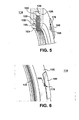
- FIG. 1 illustrates a radial side sectional view of a prior art brush seal 10 for sealing a rotating shaft.
- the brush seal 10 includes a housing 15 for mounting a brush holder 20.
- the housing includes a front plate and a backing plate for seating brush seal bristles 22.
- the bristles 22 are seated against the support surface 35 or 31 of the back plate 30 when a higher pressure P 1 is present in a first chamber 40 on one axial side of the brush seal 10 relative to the pressure P2 in a second chamber 45 on the second axial side of the brush seal.
- the housing is positioned to support the bristles in proximity to movable shaft 50.
- the brush seal bristles 22 are held in position against surface 55 of the movable shaft 50 to minimize the leakage flow 60 created by this pressure differential.
- FIG. 2 illustrates a radial side sectional view of a the prior art seal brush when, due to an operating condition of the turbomachine, pressure P 2 of the second chamber 45 on the second axial side of the brush seal is higher than the pressure P 1 of the first chamber 40 on the first axial side.
- the pressure differential forces a lower end of the bristles 22 off the support surface 35 of backing plate 30 increasing clearance 70 between the end of the bristles 22 and the surface 55 of the moving shaft 50.
- the increased clearance 70 allows a reverse flow 65 much larger than desired, resulting in a commensurate loss of high-energy fluid and efficiency of the turbomachine.
- brush seals are very effective at providing sealing during normal operation with sealing steam flow oriented in the one direction for the installed brush seals.
- the brush seal may be ineffective at sealing the reverse flow, hence requiring more auxiliary steam and a larger auxiliary boiler size to provide sealing steam.
- the present invention resides in a reverse flow tolerant brush seal for restricting a transfer of a pressurized fluid between a first chamber and a second chamber and in a turbomachine as set out in the appended claims.
- the following embodiments of the present invention have many advantages, including providing a brush seal that is responsive to sealing leakage flows from both sides of brush seal in response to changing directions of the pressure differential between the opposing sides of the seal.
- the ability to seal against leakage from both sides makes the seal effective during a wide range of operating conditions for a turbomachine, preventing loss of operating fluids and saving energy.
- the mechanism is based on spring actuation creating an axial movement of the sector arm over which the bristles are welded.
- the sector arm could be of any shape and size depending on the force balance requirements described later.
- the present invention reduces shaft flow leakages during reverse flow conditions and lowers auxiliary steam requirements during transient loads like startups, shutdowns, trips, turning gear operations. This reduces overall steam turbine auxiliary steam requirement during startup, shutdowns, trips and turning gear operations, thereby reducing the auxiliary boiler cost for the operator.
- a first embodiment of the present invention provides a brush seal that is slidingly movable along an axial direction of the rotor shaft to allow the brush seal to seal in opposite axial directions in response to alternating differential pressures across the seal.
- a first pressure exists in a first chamber on a first axial side of the seal.
- a second pressure exists in a second chamber on a second axial side of the seal.
- the chamber is given broad meaning and may include a space open to ambient. The differential pressure between the first and second chambers acts to force a flow from the high-pressure side to the low-pressure side.
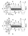
- FIG. 3 illustrates a first embodiment of the present invention of a reverse flow tolerant spring actuated brush seal.
- the inventive brush seal restricts a transfer of a pressurized fluid between a first chamber and a second chamber and may include front facing and back facing support plates, an arm sector to which the bristles may be welded, two pressure plates (P1, P2 with A1, A2 areas respectively) either bolted or welded to end faces of the piston, and a spring arrangement of stiffness K, which is placed in-between the pressure plate and one side of the backing plate.
- a housing 115 of the reverse flow tolerant brush seal 110 includes a first backing plate 125 and a second backing plate 130.
- the first backing plate 125 and the second backing plate 130 include a first support surface 126 and a second support surface 131, respectively, for the brush 122 (bristles) of the brush seal 110.
- the first backing plates 125 and the second backing plate 130 are arranged in parallel axially with respect to a moving shaft 150 being sealed, with the support surfaces 126, 131 arranged in opposition and establishing an open-ended cavity 135 therebetween.
- the cavity 135 is open-ended in a radial direction with respect to the moving shaft.
- the housing 115 is arranged to be mounted between a first chamber 140 and a second chamber 145 of a turbomachine.
- the moving shaft 150 of the turbomachine extends between the first chamber 140 and the second chamber 145.
- the housing 115 further may be arranged to physically isolate the ambient pressures, P1 in the first chamber and P2 in the second chamber from each other when mounted around the moving shaft 150.
- the moving shaft 150 may be the rotor of the turbomachine or an extension thereof.
- the housing 115 may be mounted to a fixed outer casing (not shown) of the turbomachine (not shown), thereby separating the first chamber 140 within the turbomachine and the second chamber 145 outside.
- the brush seal 110 may be formed in shape of annulus in order to fit around a circular shaft.
- the mounting of the brush seal 110 may such that sealing end 123 of the brush 122 effectively seals the moving shaft 150 when the brush seal sliding mechanism seats the brush 122 on the first seating surface 126 or the second seating surface 131.
- a brush seal arm sector 120 is adapted for suspending a plurality of seal bristles (brush) 122 within the cavity 135.
- the brush (bristles) 122 may be welded to the metal arm sector 120.
- the arm sector 120 may be formed as an arcuate shape arranged to surround a segment of the moving shaft 150.
- the brush 122 extends from the arm sector inward radially to the rotating shaft to establish a design clearance, which limits leakage.
- the arm sector 120 is integrated in a sliding brush seal mechanism 190, adapted for positioning the arm sector 120 in the cavity 135 onto the opposing backing plates 126, 131 may include a first piston 170 disposed at a first end 124 of the arm sector 120 and extending through an axial hole 171 in the first backing plate 125 to the first chamber 140.
- a second piston 175 may be disposed at a second end 127 of the arm sector 120 and extend through an axial hole 176 in the second backing plate 130 to the second chamber 145.
- the axial hole 171 in the first backing plate 125 and the axial hole 176 in the second backing plate 130 for accommodating the pistons 170, 175, respectively, are arranged coaxially.
- a first plate 180 fixedly connected to an outer end of the first piston 170 and disposed in the first chamber 140, is subject to the pressure of the first chamber.
- a second plate 185 fixedly connected to an outer end of the second piston 175, and disposed in the second chamber 145 is subject to the pressure of the second chamber.
- the plates 180, 185 may be attached by bolting, welding or other conventional attachment means.
- a plurality of plates and the associated piston sections may be provided circumferentially around the annulus of the brush seal enclosing the moving shaft.
- the sliding brush seal mechanism 190 may further include means for preferentially sliding the sector arm 120 to seat the the brush 122 against the first backing plate 125 or the second backing plate 130 in response to a differential pressure between first chamber 140 and the second chamber 145.
- the means may include a spring member 195 operably connected to the sliding brush seal mechanism 190 and opposing its travel to seat brush 122 against the first seating surface 126 or the second seating surface 131. While the spring is illustrated as being placed between the second plate 185 and the second backing plate, it is known that placement of spring devices for biasing such motion may be implemented between the first plate 180 and the first backing plate 125 or at other locations within the sliding brush seal mechanism.
- the spring 195 is arranged such that with sufficient pressure in the first chamber 140, relative to the second chamber 145, the spring force is overcome and the brush 122 of the sector arm 120 seats against the support surface 131 of the second backing plate 130. Seating of the brush 122 against the second backing plate 130 seats the brush 122 properly with respect to the surface 155 of the moving shaft 150 and seals against leakage from the first chamber 140 to the second chamber 145. In the absence of sufficient pressure in the first chamber 140 relative to the pressure in the second chamber 145, the spring 195 forces the sliding brush seal mechanism 190 to seat the brush 122 against the support surface 126 of the first backing plate 125. Seating of the brush 122 against the first backing plate 125, provides sealing from leakage directed from the second chamber 145 to the first chamber 140.
- Equation 1 represents the forces acting on the sliding brush seal mechanism and tending to seat the brush on the second backing plate:
- P 1 is the pressure of the first chamber 140;
- a 1eff 180 is an effective area on the first piston 170 acted on by P 1;
- P 2 is the pressure of the second chamber 145;
- a 2eff 186 is the effective area on the second piston 175 acted on by P 2;
- k is the spring constant;
- X 196 is a predetermined travel of the sliding brush seal mechanism 190 between two support surfaces 126, 131.
- the differential force (P 1 *A 1eff - P 2 *A 2eff + FF + CF) on the sliding brush seal must be greater than the spring restraining force k*X to cause the travel to the second backing plate 130.
- the spring force k*X aids the pressure P 2 in the second chamber 145 in seating the brush against the first backing plate 125.
- FIGs. 5-6 provide isometric view of an arcuate segment of a reverse flow tolerant brush seal.
- a first pressure plate with a rectangular geometric shape is shown on one side of the sliding brush seal mechanism.
- the rectangular plate is connected to piston extending through first backing plate and attached to arm sector.
- a pressure plate of circular geometric shape is shown connected to piston extending through the second backing plate to the arm sector.
- the plate shapes need not be limited to any particular geometry.
- the brush is seated against the first backing plate with the brush end extending inward radially from the cavity.
- FIG. 7 provides a radial-end view of the reverse tolerant brush seal housing 115.
- the end view of the housing 115 includes the first backing plate 125 surrounding the central opening 152 for a moving shaft (not shown).
- the ends 123 of the brush 122 of the multiple internal brush sectors (not shown) extend inward radially from the housing 115.
- the first pressure plates 180 for the sliding brush seal mechanisms of the multiple internal brush sectors (not shown) are located circumferentially around the first backing plate 125.
- a first piston 170 is connected axially behind each first pressure plate 180 is operably connected an internal brush sector (not shown).
- Another aspect of the present invention may include a seal 197 between an upper end closure 198 and a top surface 199 of the sector arm 120.
- the seal limits potential bypass flow over the top of the sector arm during the transitions between seating on the first backing plate 125 and seating on the second backing plate 130.
- the first chamber may be within the turbine casing and the second chamber may be ambient outside the rotor shaft.
- pressure in the turbine casing at the end of the shaft will be higher than outside pressure forcing the sliding brush seal to travels a distance X against spring force to the second backing plate, thereby supporting the bristles that maintains the brush seal design effective clearance. This also keeps the spring attached at pressure plate P2 in tension.
- the force acting on pressure plate P1 is less when compared to that of spring force and hence the spring force overcomes the pressure force and move the spring back to a position which makes the brush to move to the other end. This helps the brush to get the backing support from first backing plate, maintaining the effective clearance same as in forward flow i.e. the first backing plate will provide backing support during reverse flow condition.
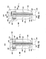
- the means for preferentially sliding the arm sector 120 may include a bellows member 270.
- the bellows member may be operably connected to the first piston 170 of the sliding brush seal mechanism 290 and may oppose its travel to seat the brush against the second support surface 131 in accordance with Equation 1 above, where P 1 is the pressure of the first chamber 140; A 1eff 281 is an effective area of the bellows 270 acted on by P 1; P 2 is the pressure of the second chamber 145; A 2eff 286 is the effective area on the second piston 175 acted on by P 2; k is the bellows constant; and X is the travel of the sliding brush seal mechanism 290 between two support surfaces 126, 131.
- the means for preferentially sliding the arm sector 120 may include an opposing cylinder arrangement.
- the opposing cylinders may be fixedly connected at opposing ends of the sliding brush seal mechanism 390 with a restraining spring 195 so as to oppose travel of the brush seal sliding mechanism to seat the brush 122 against the second support surface 131 in accordance with Equation 1 above, where P 1 is the pressure of the first chamber 140; A 1eff 381 is an effective area of a first cylinder acted on by P 1; P 2 is the pressure of the second chamber 145; A 2eff 386 is the effective area of the second cylinder acted on by P 2; k is the spring constant of the restraining spring 195; and X 196 is the travel of the brush 122 between two support surfaces 126, 131.
- FIG. 1 may depict a piezoelectric material, inflatable tubes, bourdon tubes, pneumatic and hydraulic actuation, cams, and electro-magnetic actuators for axial retraction of the piston to change the sector position.
- the size and shape of the pressure plates, pistons, cylinders, and bellow can also be altered based on the requirements such as size and pressures imposed.
- a telescopic arm arrangement with the helical spring placed inside the cylinder will serve the purpose of axial movement of brush seal.
- FIG. 10 illustrates another embodiment of the reverse flow tolerant brush seal 410.
- a floating brush assembly 420 is provided within a housing 415 that includes an internal cavity 435 with an arcuate plate 480 operated on by a spring 495 to move the floating brush assembly 420 in an axial orientation based on upstream and downstream pressure as illustrated in FIG. 10 .
- the housing 415 includes a first backing plate 425 with a support surface 426 and a second backing plate 430 with a supporting surface 431.
- the housing 415 includes the open-ended cavity 435 between the opposing backing plates.
- the open end 436 of the cavity 435 provides for a brush 422 of the brush seal 410 to extend to an external moving shaft 450 for sealing the shaft.
- the cavity 435 may include an upper annular segment 470.
- the spring 495, the arcuate plate 480 and the floating brush assembly 420 are housed in the upper annular segment along an axial direction with respect to the external moving shaft 450.
- the spring 495 acts on the arcuate plate 480 biasing movement of the floating brush assembly 420.
- a radial clearance 485 is provided between the outer radial surface 470 of the floating brush assembly and an inner radial surface 471 of the housing 415 to allow axial motion of the floating brush assembly.
- Multiple axial throughholes 497 may be provided at circumferential locations on backing plate 430, exposing the associated side of brush seal assembly 420 to pressure from chamber 445.
- a further embodiment of the use of a floating brush assembly may include a pocket and a ripple spring in lieu of the spring 495 and arcuate plate 480. Such a pocket and ripple spring may provide a thinner and lower cost assembly.
- FIG. 11 A further variation of the above embodiment for a reverse flow tolerant brush seal 510 is illustrated in FIG. 11 .
- the upper annular segment of cavity includes an expanded radial section 520.
- a radial spring 525 and a rolled plate 530 Within the radial section 520 is included a radial spring 525 and a rolled plate 530.
- the spring 525 and rolled plate 530 apply an inward radial force to the floating brush assembly 420 and thereby smooth axial motion in response to the pressure differential between the first chamber 440 and the second chamber 445.
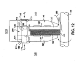
- FIG. 12 illustrates a reverse flow tolerant brush seal 1210 with bellows 270 that does not employ spring biasing.
Landscapes
- Engineering & Computer Science (AREA)
- General Engineering & Computer Science (AREA)
- Mechanical Engineering (AREA)
- Turbine Rotor Nozzle Sealing (AREA)
- Sealing Devices (AREA)
Applications Claiming Priority (1)
| Application Number | Priority Date | Filing Date | Title |
|---|---|---|---|
| US12/706,102 US8317464B2 (en) | 2010-02-16 | 2010-02-16 | Reverse flow tolerant spring activated brush seal |
Publications (2)
| Publication Number | Publication Date |
|---|---|
| EP2357385A1 EP2357385A1 (en) | 2011-08-17 |
| EP2357385B1 true EP2357385B1 (en) | 2015-10-28 |
Family
ID=44020201
Family Applications (1)
| Application Number | Title | Priority Date | Filing Date |
|---|---|---|---|
| EP11154454.0A Not-in-force EP2357385B1 (en) | 2010-02-16 | 2011-02-15 | Reverse flow tolerant spring activated brush seal |
Country Status (4)
| Country | Link |
|---|---|
| US (1) | US8317464B2 (https=) |
| EP (1) | EP2357385B1 (https=) |
| JP (1) | JP5819072B2 (https=) |
| RU (1) | RU2537325C2 (https=) |
Families Citing this family (29)
| Publication number | Priority date | Publication date | Assignee | Title |
|---|---|---|---|---|
| DE102008006485A1 (de) * | 2008-01-29 | 2009-07-30 | Mtu Aero Engines Gmbh | Bürstendichtung und Verfahren zur Montage einer Bürstendichtung |
| EP2105640B1 (de) * | 2008-03-28 | 2011-04-27 | Alstom Technology Ltd | Blattdichtung für Turbomaschine |
| US8632074B2 (en) * | 2008-07-14 | 2014-01-21 | Cross Manufacturing Company (1938) Limited | Method of forming a brush seal |
| US8505923B2 (en) * | 2009-08-31 | 2013-08-13 | Sealeze, A Unit of Jason, Inc. | Brush seal with stress and deflection accommodating membrane |
| WO2011028578A2 (en) * | 2009-09-01 | 2011-03-10 | Corsolutions, Llc | Microfluidic interface |
| US8794918B2 (en) * | 2011-01-07 | 2014-08-05 | General Electric Company | System for adjusting brush seal segments in turbomachine |
| US9121297B2 (en) | 2011-03-28 | 2015-09-01 | General Electric Company | Rotating brush seal |
| US9255486B2 (en) | 2011-03-28 | 2016-02-09 | General Electric Company | Rotating brush seal |
| WO2012170514A2 (en) * | 2011-06-07 | 2012-12-13 | Sealeze, A Unit Of Jason Incorporated | Quick change brush seal retaining arrangement |
| US8632075B2 (en) * | 2011-08-08 | 2014-01-21 | General Electric Company | Seal assembly and method for flowing hot gas in a turbine |
| JP5804893B2 (ja) | 2011-10-26 | 2015-11-04 | 三菱重工業株式会社 | 軸シール装置及びこれを備える回転機械 |
| GB201200290D0 (en) | 2012-01-10 | 2012-02-22 | Rolls Royce Plc | Gas turbine engine buffer seals |
| CN104583650B (zh) * | 2013-02-06 | 2017-07-14 | 伊格尔工业股份有限公司 | 毛刷密封装置 |
| WO2014123190A1 (ja) | 2013-02-06 | 2014-08-14 | イーグル工業株式会社 | ブラシシール装置 |
| JP6191844B2 (ja) | 2013-10-18 | 2017-09-06 | 三菱重工業株式会社 | 軸シール装置、及びこれを備える回転機械 |
| CN105275505B (zh) * | 2014-06-09 | 2017-06-16 | 斗山重工业株式会社 | 刷式密封组件 |
| DE102015201401B4 (de) * | 2015-01-28 | 2021-06-17 | MTU Aero Engines AG | Vorrichtung und Verfahren zur Befestigung von Dichtungselementen |
| EP3252353B1 (en) * | 2015-01-29 | 2019-12-25 | Eagle Industry Co., Ltd. | Brush seal |
| CN105443164A (zh) * | 2015-12-31 | 2016-03-30 | 沈阳航空航天大学 | 一种后挡板具有台阶式环形凸台的刷式密封结构 |
| KR101638480B1 (ko) * | 2016-03-25 | 2016-07-11 | 터보파워텍(주) | 터빈용 브러시 실링장치 |
| KR101904227B1 (ko) * | 2016-04-12 | 2018-10-05 | 한국과학기술연구원 | 베어링의 오일 밀봉 장치 |
| US10962117B2 (en) | 2017-12-18 | 2021-03-30 | Raytheon Technologies Corporation | Brush seal with spring-loaded backing plate |
| GB201814674D0 (en) * | 2018-09-10 | 2018-10-24 | Rolls Royce Plc | Radially dispaceable brush seal |
| US11428323B2 (en) * | 2019-04-16 | 2022-08-30 | Raytheon Technologies Corporation | Floating brush seal assembly |
| US11619174B2 (en) | 2020-02-14 | 2023-04-04 | Raytheon Technologies Corporation | Combustor to vane sealing assembly and method of forming same |
| CN111663963B (zh) * | 2020-05-14 | 2021-06-04 | 复旦大学 | 一种可调节末级压降的多级刷式密封结构 |
| US11519288B2 (en) * | 2020-12-18 | 2022-12-06 | General Electric Company | Turbomachine clearance control using brush seals having magnetically responsive filaments |
| RU207268U1 (ru) * | 2021-06-09 | 2021-10-21 | Акционерное общество (АО) "Научно-исследовательский институт "Лопастных машин" ("НИИ ЛМ") | Щелевое радиальное уплотнение для загрязненных жидкостей между вращающейся и невращающейся деталями |
| US20240413701A1 (en) * | 2023-06-09 | 2024-12-12 | Schaeffler Technologies AG & Co. KG | Seal for linear actuator |
Family Cites Families (21)
| Publication number | Priority date | Publication date | Assignee | Title |
|---|---|---|---|---|
| SU1462916A1 (ru) * | 1987-06-15 | 1996-10-10 | В.Е. Резник | Способ изготовления щеточного уплотнения |
| SU1665136A1 (ru) * | 1989-07-11 | 1991-07-23 | Куйбышевский авиационный институт им.акад.С.П.Королева | Щеточное уплотнение |
| US5678898A (en) * | 1995-04-17 | 1997-10-21 | General Electric Company | Method for making a brush seal |
| US5997004A (en) * | 1996-10-22 | 1999-12-07 | Flowserve Management Company | Hybrid floating brush seal |
| DE19712088C2 (de) | 1997-03-22 | 1999-06-24 | Mtu Muenchen Gmbh | Bürstendichtung mit in Umfangsrichtung schräg gestellten Borsten |
| US6231047B1 (en) * | 1998-05-29 | 2001-05-15 | Eg&G Engineered Products | Brush seal |
| DE19855742C1 (de) | 1998-12-03 | 2000-09-14 | Mtu Muenchen Gmbh | Bürstendichtung mit abgewinkelten Borsten |
| JP2001050396A (ja) * | 1999-08-05 | 2001-02-23 | Toshiba Corp | ブラシシール装置 |
| US6226975B1 (en) * | 1999-09-14 | 2001-05-08 | Steven G. Ingistov | Turbine power plant having a floating brush seal |
| GB9930620D0 (en) | 1999-12-24 | 2000-02-16 | Cross Mfg Co | Brush seals |
| US6807290B2 (en) * | 2000-03-09 | 2004-10-19 | Microsoft Corporation | Rapid computer modeling of faces for animation |
| RU2210694C2 (ru) * | 2001-10-01 | 2003-08-20 | Федеральное государственное унитарное предприятие "Центральный институт авиационного моторостроения" им. П.И.Баранова | Способ изготовления щеточного уплотнения и устройство для его осуществления |
| US6840519B2 (en) * | 2001-10-30 | 2005-01-11 | General Electric Company | Actuating mechanism for a turbine and method of retrofitting |
| US6786487B2 (en) * | 2001-12-05 | 2004-09-07 | General Electric Company | Actuated brush seal |
| DE10324709A1 (de) * | 2003-05-30 | 2004-12-16 | Mtu Aero Engines Gmbh | Bürstendichtung zum Abdichten relativ zueinander beweglicher Bauteile gegenüber einem Druckgefälle |
| US7413194B2 (en) * | 2004-10-28 | 2008-08-19 | Rolls-Royce Plc | Pressure balanced annular seal |
| US7458584B2 (en) * | 2007-02-27 | 2008-12-02 | United Technologies Corporation | Reverse flow tolerant brush seal |
| US7744092B2 (en) * | 2007-04-30 | 2010-06-29 | General Electric Company | Methods and apparatus to facilitate sealing in rotary machines |
| EP2085575A1 (de) * | 2008-02-01 | 2009-08-05 | Siemens Aktiengesellschaft | Kombination von Bürstendichtung mit Kolbenring für grosse Dichtspalte |
| EP2105640B1 (de) * | 2008-03-28 | 2011-04-27 | Alstom Technology Ltd | Blattdichtung für Turbomaschine |
| GB2461506B (en) * | 2008-06-30 | 2010-08-25 | Rolls Royce Plc | A seal arrangement |
-
2010
- 2010-02-16 US US12/706,102 patent/US8317464B2/en not_active Expired - Fee Related
-
2011
- 2011-02-10 JP JP2011026622A patent/JP5819072B2/ja not_active Expired - Fee Related
- 2011-02-15 RU RU2011106272/06A patent/RU2537325C2/ru not_active IP Right Cessation
- 2011-02-15 EP EP11154454.0A patent/EP2357385B1/en not_active Not-in-force
Also Published As
| Publication number | Publication date |
|---|---|
| RU2537325C2 (ru) | 2015-01-10 |
| JP2011169319A (ja) | 2011-09-01 |
| EP2357385A1 (en) | 2011-08-17 |
| US20110200432A1 (en) | 2011-08-18 |
| JP5819072B2 (ja) | 2015-11-18 |
| US8317464B2 (en) | 2012-11-27 |
| RU2011106272A (ru) | 2012-08-20 |
Similar Documents
| Publication | Publication Date | Title |
|---|---|---|
| EP2357385B1 (en) | Reverse flow tolerant spring activated brush seal | |
| JP5329248B2 (ja) | 引込み弾性プレートシール | |
| US6655696B1 (en) | Seal carrier for a rotary machine and method of retrofitting | |
| JP5830247B2 (ja) | ラビリンスシールパッキングリングの方法及び装置 | |
| JP5864912B2 (ja) | ラビリンスシールのパッキンリングのための方法および装置 | |
| US7125223B2 (en) | Method and apparatus for turbomachine active clearance control | |
| US6502823B1 (en) | Actuating seal carrier for a turbine and method of retrofitting | |
| US8262349B2 (en) | Adaptive compliant plate seal assemblies and methods | |
| US6685427B1 (en) | Brush seal for a rotary machine and method of retrofitting | |
| EP1380778A1 (en) | Seal | |
| EP1965108B1 (en) | Reverse flow tolerant brush seal | |
| US10359117B2 (en) | Aspirating face seal with non-coiled retraction springs | |
| JP2014505204A (ja) | 軸方向ブラシシール | |
| EP3002487B1 (en) | Sealing system | |
| US20120326393A1 (en) | Brush seal | |
| US6692228B2 (en) | Rotor insert assembly and method of retrofitting | |
| WO2011162330A1 (ja) | 軸シール機構、及びこれを備えた回転機械 | |
| EP2020542A1 (en) | Seal assembly | |
| EP1660796B1 (en) | Seal carrier for a rotary machine and method of retrofitting | |
| KR101771216B1 (ko) | 터빈용 복합 실링장치 | |
| US20220307603A1 (en) | Non-contact seal assembly with damping elements |
Legal Events
| Date | Code | Title | Description |
|---|---|---|---|
| PUAI | Public reference made under article 153(3) epc to a published international application that has entered the european phase |
Free format text: ORIGINAL CODE: 0009012 |
|
| AK | Designated contracting states |
Kind code of ref document: A1 Designated state(s): AL AT BE BG CH CY CZ DE DK EE ES FI FR GB GR HR HU IE IS IT LI LT LU LV MC MK MT NL NO PL PT RO RS SE SI SK SM TR |
|
| AX | Request for extension of the european patent |
Extension state: BA ME |
|
| 17P | Request for examination filed |
Effective date: 20120217 |
|
| GRAP | Despatch of communication of intention to grant a patent |
Free format text: ORIGINAL CODE: EPIDOSNIGR1 |
|
| GRAJ | Information related to disapproval of communication of intention to grant by the applicant or resumption of examination proceedings by the epo deleted |
Free format text: ORIGINAL CODE: EPIDOSDIGR1 |
|
| INTG | Intention to grant announced |
Effective date: 20141008 |
|
| INTC | Intention to grant announced (deleted) | ||
| GRAJ | Information related to disapproval of communication of intention to grant by the applicant or resumption of examination proceedings by the epo deleted |
Free format text: ORIGINAL CODE: EPIDOSDIGR1 |
|
| GRAP | Despatch of communication of intention to grant a patent |
Free format text: ORIGINAL CODE: EPIDOSNIGR1 |
|
| INTG | Intention to grant announced |
Effective date: 20150616 |
|
| GRAS | Grant fee paid |
Free format text: ORIGINAL CODE: EPIDOSNIGR3 |
|
| GRAA | (expected) grant |
Free format text: ORIGINAL CODE: 0009210 |
|
| AK | Designated contracting states |
Kind code of ref document: B1 Designated state(s): AL AT BE BG CH CY CZ DE DK EE ES FI FR GB GR HR HU IE IS IT LI LT LU LV MC MK MT NL NO PL PT RO RS SE SI SK SM TR |
|
| REG | Reference to a national code |
Ref country code: GB Ref legal event code: FG4D |
|
| REG | Reference to a national code |
Ref country code: CH Ref legal event code: EP |
|
| REG | Reference to a national code |
Ref country code: AT Ref legal event code: REF Ref document number: 758137 Country of ref document: AT Kind code of ref document: T Effective date: 20151115 |
|
| REG | Reference to a national code |
Ref country code: IE Ref legal event code: FG4D |
|
| REG | Reference to a national code |
Ref country code: DE Ref legal event code: R096 Ref document number: 602011020935 Country of ref document: DE |
|
| REG | Reference to a national code |
Ref country code: LT Ref legal event code: MG4D |
|
| REG | Reference to a national code |
Ref country code: NL Ref legal event code: MP Effective date: 20151028 |
|
| REG | Reference to a national code |
Ref country code: AT Ref legal event code: MK05 Ref document number: 758137 Country of ref document: AT Kind code of ref document: T Effective date: 20151028 |
|
| PG25 | Lapsed in a contracting state [announced via postgrant information from national office to epo] |
Ref country code: ES Free format text: LAPSE BECAUSE OF FAILURE TO SUBMIT A TRANSLATION OF THE DESCRIPTION OR TO PAY THE FEE WITHIN THE PRESCRIBED TIME-LIMIT Effective date: 20151028 Ref country code: HR Free format text: LAPSE BECAUSE OF FAILURE TO SUBMIT A TRANSLATION OF THE DESCRIPTION OR TO PAY THE FEE WITHIN THE PRESCRIBED TIME-LIMIT Effective date: 20151028 Ref country code: NL Free format text: LAPSE BECAUSE OF FAILURE TO SUBMIT A TRANSLATION OF THE DESCRIPTION OR TO PAY THE FEE WITHIN THE PRESCRIBED TIME-LIMIT Effective date: 20151028 Ref country code: IS Free format text: LAPSE BECAUSE OF FAILURE TO SUBMIT A TRANSLATION OF THE DESCRIPTION OR TO PAY THE FEE WITHIN THE PRESCRIBED TIME-LIMIT Effective date: 20160228 Ref country code: LT Free format text: LAPSE BECAUSE OF FAILURE TO SUBMIT A TRANSLATION OF THE DESCRIPTION OR TO PAY THE FEE WITHIN THE PRESCRIBED TIME-LIMIT Effective date: 20151028 Ref country code: NO Free format text: LAPSE BECAUSE OF FAILURE TO SUBMIT A TRANSLATION OF THE DESCRIPTION OR TO PAY THE FEE WITHIN THE PRESCRIBED TIME-LIMIT Effective date: 20160128 |
|
| PG25 | Lapsed in a contracting state [announced via postgrant information from national office to epo] |
Ref country code: SE Free format text: LAPSE BECAUSE OF FAILURE TO SUBMIT A TRANSLATION OF THE DESCRIPTION OR TO PAY THE FEE WITHIN THE PRESCRIBED TIME-LIMIT Effective date: 20151028 Ref country code: LV Free format text: LAPSE BECAUSE OF FAILURE TO SUBMIT A TRANSLATION OF THE DESCRIPTION OR TO PAY THE FEE WITHIN THE PRESCRIBED TIME-LIMIT Effective date: 20151028 Ref country code: PL Free format text: LAPSE BECAUSE OF FAILURE TO SUBMIT A TRANSLATION OF THE DESCRIPTION OR TO PAY THE FEE WITHIN THE PRESCRIBED TIME-LIMIT Effective date: 20151028 Ref country code: FI Free format text: LAPSE BECAUSE OF FAILURE TO SUBMIT A TRANSLATION OF THE DESCRIPTION OR TO PAY THE FEE WITHIN THE PRESCRIBED TIME-LIMIT Effective date: 20151028 Ref country code: GR Free format text: LAPSE BECAUSE OF FAILURE TO SUBMIT A TRANSLATION OF THE DESCRIPTION OR TO PAY THE FEE WITHIN THE PRESCRIBED TIME-LIMIT Effective date: 20160129 Ref country code: AT Free format text: LAPSE BECAUSE OF FAILURE TO SUBMIT A TRANSLATION OF THE DESCRIPTION OR TO PAY THE FEE WITHIN THE PRESCRIBED TIME-LIMIT Effective date: 20151028 Ref country code: RS Free format text: LAPSE BECAUSE OF FAILURE TO SUBMIT A TRANSLATION OF THE DESCRIPTION OR TO PAY THE FEE WITHIN THE PRESCRIBED TIME-LIMIT Effective date: 20151028 Ref country code: PT Free format text: LAPSE BECAUSE OF FAILURE TO SUBMIT A TRANSLATION OF THE DESCRIPTION OR TO PAY THE FEE WITHIN THE PRESCRIBED TIME-LIMIT Effective date: 20160229 Ref country code: BE Free format text: LAPSE BECAUSE OF NON-PAYMENT OF DUE FEES Effective date: 20160229 |
|
| PG25 | Lapsed in a contracting state [announced via postgrant information from national office to epo] |
Ref country code: CZ Free format text: LAPSE BECAUSE OF FAILURE TO SUBMIT A TRANSLATION OF THE DESCRIPTION OR TO PAY THE FEE WITHIN THE PRESCRIBED TIME-LIMIT Effective date: 20151028 |
|
| REG | Reference to a national code |
Ref country code: DE Ref legal event code: R097 Ref document number: 602011020935 Country of ref document: DE |
|
| PG25 | Lapsed in a contracting state [announced via postgrant information from national office to epo] |
Ref country code: DK Free format text: LAPSE BECAUSE OF FAILURE TO SUBMIT A TRANSLATION OF THE DESCRIPTION OR TO PAY THE FEE WITHIN THE PRESCRIBED TIME-LIMIT Effective date: 20151028 Ref country code: SM Free format text: LAPSE BECAUSE OF FAILURE TO SUBMIT A TRANSLATION OF THE DESCRIPTION OR TO PAY THE FEE WITHIN THE PRESCRIBED TIME-LIMIT Effective date: 20151028 Ref country code: SK Free format text: LAPSE BECAUSE OF FAILURE TO SUBMIT A TRANSLATION OF THE DESCRIPTION OR TO PAY THE FEE WITHIN THE PRESCRIBED TIME-LIMIT Effective date: 20151028 Ref country code: RO Free format text: LAPSE BECAUSE OF FAILURE TO SUBMIT A TRANSLATION OF THE DESCRIPTION OR TO PAY THE FEE WITHIN THE PRESCRIBED TIME-LIMIT Effective date: 20151028 Ref country code: EE Free format text: LAPSE BECAUSE OF FAILURE TO SUBMIT A TRANSLATION OF THE DESCRIPTION OR TO PAY THE FEE WITHIN THE PRESCRIBED TIME-LIMIT Effective date: 20151028 |
|
| PLBE | No opposition filed within time limit |
Free format text: ORIGINAL CODE: 0009261 |
|
| STAA | Information on the status of an ep patent application or granted ep patent |
Free format text: STATUS: NO OPPOSITION FILED WITHIN TIME LIMIT |
|
| PG25 | Lapsed in a contracting state [announced via postgrant information from national office to epo] |
Ref country code: LU Free format text: LAPSE BECAUSE OF FAILURE TO SUBMIT A TRANSLATION OF THE DESCRIPTION OR TO PAY THE FEE WITHIN THE PRESCRIBED TIME-LIMIT Effective date: 20160215 Ref country code: MC Free format text: LAPSE BECAUSE OF FAILURE TO SUBMIT A TRANSLATION OF THE DESCRIPTION OR TO PAY THE FEE WITHIN THE PRESCRIBED TIME-LIMIT Effective date: 20151028 |
|
| 26N | No opposition filed |
Effective date: 20160729 |
|
| REG | Reference to a national code |
Ref country code: FR Ref legal event code: ST Effective date: 20161028 |
|
| PG25 | Lapsed in a contracting state [announced via postgrant information from national office to epo] |
Ref country code: SI Free format text: LAPSE BECAUSE OF FAILURE TO SUBMIT A TRANSLATION OF THE DESCRIPTION OR TO PAY THE FEE WITHIN THE PRESCRIBED TIME-LIMIT Effective date: 20151028 |
|
| REG | Reference to a national code |
Ref country code: IE Ref legal event code: MM4A |
|
| PG25 | Lapsed in a contracting state [announced via postgrant information from national office to epo] |
Ref country code: BE Free format text: LAPSE BECAUSE OF FAILURE TO SUBMIT A TRANSLATION OF THE DESCRIPTION OR TO PAY THE FEE WITHIN THE PRESCRIBED TIME-LIMIT Effective date: 20151028 |
|
| PG25 | Lapsed in a contracting state [announced via postgrant information from national office to epo] |
Ref country code: FR Free format text: LAPSE BECAUSE OF NON-PAYMENT OF DUE FEES Effective date: 20160229 Ref country code: IE Free format text: LAPSE BECAUSE OF NON-PAYMENT OF DUE FEES Effective date: 20160215 |
|
| PGFP | Annual fee paid to national office [announced via postgrant information from national office to epo] |
Ref country code: CH Payment date: 20170227 Year of fee payment: 7 |
|
| PG25 | Lapsed in a contracting state [announced via postgrant information from national office to epo] |
Ref country code: MT Free format text: LAPSE BECAUSE OF FAILURE TO SUBMIT A TRANSLATION OF THE DESCRIPTION OR TO PAY THE FEE WITHIN THE PRESCRIBED TIME-LIMIT Effective date: 20151028 |
|
| PG25 | Lapsed in a contracting state [announced via postgrant information from national office to epo] |
Ref country code: HU Free format text: LAPSE BECAUSE OF FAILURE TO SUBMIT A TRANSLATION OF THE DESCRIPTION OR TO PAY THE FEE WITHIN THE PRESCRIBED TIME-LIMIT; INVALID AB INITIO Effective date: 20110215 Ref country code: CY Free format text: LAPSE BECAUSE OF FAILURE TO SUBMIT A TRANSLATION OF THE DESCRIPTION OR TO PAY THE FEE WITHIN THE PRESCRIBED TIME-LIMIT Effective date: 20151028 |
|
| PG25 | Lapsed in a contracting state [announced via postgrant information from national office to epo] |
Ref country code: MK Free format text: LAPSE BECAUSE OF FAILURE TO SUBMIT A TRANSLATION OF THE DESCRIPTION OR TO PAY THE FEE WITHIN THE PRESCRIBED TIME-LIMIT Effective date: 20151028 Ref country code: MT Free format text: LAPSE BECAUSE OF FAILURE TO SUBMIT A TRANSLATION OF THE DESCRIPTION OR TO PAY THE FEE WITHIN THE PRESCRIBED TIME-LIMIT Effective date: 20160229 Ref country code: TR Free format text: LAPSE BECAUSE OF FAILURE TO SUBMIT A TRANSLATION OF THE DESCRIPTION OR TO PAY THE FEE WITHIN THE PRESCRIBED TIME-LIMIT Effective date: 20151028 |
|
| PG25 | Lapsed in a contracting state [announced via postgrant information from national office to epo] |
Ref country code: BG Free format text: LAPSE BECAUSE OF FAILURE TO SUBMIT A TRANSLATION OF THE DESCRIPTION OR TO PAY THE FEE WITHIN THE PRESCRIBED TIME-LIMIT Effective date: 20151028 |
|
| REG | Reference to a national code |
Ref country code: CH Ref legal event code: PL |
|
| PG25 | Lapsed in a contracting state [announced via postgrant information from national office to epo] |
Ref country code: AL Free format text: LAPSE BECAUSE OF FAILURE TO SUBMIT A TRANSLATION OF THE DESCRIPTION OR TO PAY THE FEE WITHIN THE PRESCRIBED TIME-LIMIT Effective date: 20151028 |
|
| PG25 | Lapsed in a contracting state [announced via postgrant information from national office to epo] |
Ref country code: LI Free format text: LAPSE BECAUSE OF NON-PAYMENT OF DUE FEES Effective date: 20180228 Ref country code: CH Free format text: LAPSE BECAUSE OF NON-PAYMENT OF DUE FEES Effective date: 20180228 |
|
| PGFP | Annual fee paid to national office [announced via postgrant information from national office to epo] |
Ref country code: GB Payment date: 20200123 Year of fee payment: 10 |
|
| GBPC | Gb: european patent ceased through non-payment of renewal fee |
Effective date: 20210215 |
|
| PG25 | Lapsed in a contracting state [announced via postgrant information from national office to epo] |
Ref country code: GB Free format text: LAPSE BECAUSE OF NON-PAYMENT OF DUE FEES Effective date: 20210215 |
|
| PGFP | Annual fee paid to national office [announced via postgrant information from national office to epo] |
Ref country code: DE Payment date: 20220119 Year of fee payment: 12 |
|
| PGFP | Annual fee paid to national office [announced via postgrant information from national office to epo] |
Ref country code: IT Payment date: 20220119 Year of fee payment: 12 |
|
| REG | Reference to a national code |
Ref country code: DE Ref legal event code: R119 Ref document number: 602011020935 Country of ref document: DE |
|
| PG25 | Lapsed in a contracting state [announced via postgrant information from national office to epo] |
Ref country code: IT Free format text: LAPSE BECAUSE OF NON-PAYMENT OF DUE FEES Effective date: 20230215 Ref country code: DE Free format text: LAPSE BECAUSE OF NON-PAYMENT OF DUE FEES Effective date: 20230901 |